Harley Davidson 2005 MOTORCYCLE. PREDELIVERY AND SETUP MANUAL - page 3


  Главная      Manuals     Harley Davidson 2005 MOTORCYCLE. PREDELIVERY AND SETUP MANUAL


Search            copyright infringement  


Content      ..     1      2      3      4      ..


Harley Davidson 2005 MOTORCYCLE. PREDELIVERY AND SETUP MANUAL - page 3


-------------------------------------------------------------------------------------------------------------------------------------------------------------
BRAKE SYSTEM
2.7
BRAKES
6628
1CAUTION
Direct contact of D.O.T. 4 brake fluid with eyes can cause
irritation. Avoid eye contact. In case of eye contact flush
with large amounts of water and get medical attention.
Swallowing large amounts of D.O.T. 4 brake fluid can
cause digestive discomfort. If swallowed, obtain medical
attention. Use in well ventilated area. KEEP OUT OF
REACH OF CHILDREN. (00240a)
CAUTION
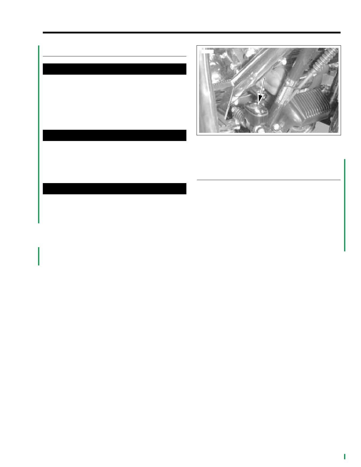
Figure 2-22. Rear Brake Reservoir/Master Cylinder Sight-
D.O.T. 4 brake fluid will damage painted and molded-in
glass (typical)
color surfaces it comes in contact with. Always use cau-
tion and protect surfaces from spills whenever brake
ABS SYSTEM (POLICE VEHICLES-
work is performed. Failure to comply can result in cos-
metic damage. (00239a)
OPTIONAL EQUIPMENT)
The ABS indicator lamp in the tachometer will flash when the
CAUTION
ignition switch is turned on, and remains flashing until the
Cover handlebar switches with a shop towel before add-
motorcycle reaches 6 MPH (9.7 KPH). The lamp will then turn
ing brake fluid to front master cylinder reservoir. Spilling
off.
brake fluid on handlebar switches may render them inop-
If the ABS lamp turns on solid at ignition-ON, or does not turn
erative.
off when vehicle exceeds 6 MPH (9.7 KPH), it is an indication
See Figure 2-22. View reservoir sightglass and verify fluid
of a current fault condition in the ABS system. See the Police
presence. Sightglass should appear dark if fluid is present. If
Models Service Manual Supplement for instructions on plac-
sightglass is not dark, add brake fluid. See Service Manual.
ing the ABS system into test mode and extracting diagnostic
Use only D.O.T. 4 HYDRAULIC BRAKE FLUID (Part No.
trouble codes from the ABS system computer.
99953-99A). Wash all residue of D.O.T. 4 brake fluid spills off
vehicle with water.
2005 PDI: Touring Models
2-19

-------------------------------------------------------------------------------------------------------------------------------------------------------------

DEALER ROAD TEST
2.8
ROAD TEST
IDLE SPEED: CARBURETED ONLY
After you complete motorcycle inspection, take motorcycle for
NOTE
a road test. Check all systems and overall operation of motor-
The idle speed on fuel injected models can only be set using
cycle: engine, transmission, clutch, brakes, handling, etc. On
a diagnostic tool such as DIGITAL TECHNICIAN (Part No.
Ultra models, check Cruise Control, rear speakers and rider/
HD-44750).
passenger sound system controls. Refer to Touring Models
Owner’s Manual to check for proper operation.
See Figure 2-23. Set engine slow idle speed of 950 RPM with
engine running at normal operating temperature and with
After road test, return motorcycle to shop and thoroughly
enrichment control knob pushed in fully. Turn carburetor idle
clean off any road dirt. Check and correct any problems you
speed adjusting screw (5) clockwise to increase speed, or
may have found during road test.
counterclockwise to decrease speed.
Before You Begin
NOTE
The C.V. carburetor has an enrichment circuit that will cause
Check the following items before road test of vehicle:
the engine to idle above the normal idle range (950-1050
Lamps and indicators.
RPM) with the engine at normal operating temperature and
Check amount of gasoline in tank and add
(if
the enrichment knob pulled out fully. The increase in idle
needed).
speed is intended to alert the rider that the engine is warmed
Adjust mirrors to proper riding positions.
up to normal operating temperature and that the enrichment
Check tire condition and pressure (adjust if neces-
knob should be pushed in all the way. Continuing to use the
sary).
enrichener when the engine is at full operating temperature
Check controls to verify proper function.
will cause fouled plugs.
Check all electrical equipment and switches includ-
Be sure the engine is warmed up to normal operating temper-
ing stop lamp, turn signals and horn for proper oper-
ature and the enrichment knob is pushed all the way in before
ation.
adjusting engine idle speed. Be aware that, because there
are variations in individual components, it is possible for a
Road Test of Vehicle: Low Speed
properly warmed-up engine to idle above the normal idle
1. Shift from first through third gear, checking clutch opera-
range (950-1050 RPM) with the enrichment knob pulled out
tion, throttle control, and transmission operation.
partially.
2. Verify low-speed braking for front and rear brakes.
3. Handling under braking conditions.
f1381a2x
4. Low speed handling. Verify that vehicle does not pull to
left or right.
5
5. Check for any abnormal vibrations.
6. Check electrical lamps, indicators.
Road Test of Vehicle: Highway Speed
1. Shift from first through fifth gear, checking clutch opera-
tion, throttle control and transmission operation.
2. Verify highway-speed braking operation of front and rear
2
brakes.
3. Verify proper handling at highway speeds.
3
4. Check for any abnormal vibrations.
Program Security System (if equipped)
4
Engine Oil:
1
1. Carburetor stop plate
Check and correct hot level.
2. Cable housing
Clean Vehicle
3. Spring
4. Throttle cam stop
NOTE
5. Idle speed adjusting screw
Be sure to submit a Dealer Product Quality Audit (DPQA) on
ANY adjustments and/or warranty work performed required to
deliver the vehicle to the customer.
Figure 2-23. Carburetor Adjustments
2-20
2005 PDI: Touring Models

-------------------------------------------------------------------------------------------------------------------------------------------------------------

CUSTOMER DELIVERY
2.9
IMPORTANT NOTE
NOTICE TO DEALER
Make sure vehicle owner understands how to arm and
disarm security system. Explain how to disarm security
Before delivering motorcycle to owner, perform the following:
system with personal code if key fob is lost or not func-
1. Make sure vehicle owner receives, and is aware of
tioning. Personal code should be written on the tear-out
importance of reading Owner’s Manual, safety booklets
card in Touring Models Owner’s Manual and kept on the
and viewing Welcome To The Family video included with
owner’s person. Also, verify both key fobs operate prop-
owner’s kit.
erly.
2. Review warranties with vehicle owner. Make sure owner
9. Whenever possible, introduce dealer Service Manager to
understands warranties. California dealers must give
vehicle owner, and involve Service Manager in delivery
customer a copy of Emissions Control System Warranty.
process. Supply owner with name(s) of dealer Service/
3. Give IMPORTANT sheet and other printed material in lit-
Parts Department personnel who should be contacted
erature kit to vehicle owner.
regarding vehicle service/parts questions.
4. Complete and sign warranty registration form. Have vehi-
10. Inform vehicle owner about checking engine oil level,
cle owner sign it.
checking tire pressure, and performing other basic main-
5. Explain operation of vehicle controls to vehicle owner.
tenance functions. Review the Initial Scheduled Main-
tenance requirement with owner. Depending on owner’s
6. Explain how turn signals and emergency flashers oper-
anticipated frequency of operating motorcycle, you may
ate.
wish to schedule the Initial Scheduled Maintenance
7. If motorcycle is equipped with a Sound System, explain
service appointment at this time.
to customer that the Touring Models Owner’s Manual
contains detailed operating instructions for the system. In
addition, a video has been prepared to give the customer
operating instructions for the Sound System. On Ultra
models, tell customer helmet headset is shipped in sad-
dlebag.
8. Inform vehicle owner about changing TSM/TSSM to
sidecar or solo configuration as appropriate.
2005 PDI: Touring Models
2-21

-------------------------------------------------------------------------------------------------------------------------------------------------------------

VEHICLE PDI CHECKLIST
2.10
Fuel Outlet (valve or quick connect fitting)
PRIOR TO CUSTOMER DELIVERY
and Hoses:
Verify operation and connections.
NOTE
Evaporative Control System:
Use this checklist for performing tasks related to this model
motorcycle setup.
Inspect hose routings, connections and fuel tank venting
to canister (if equipped).
Uncrate:
Lighting, Gauges, Electrical Systems:
Check for damaged or missing parts.
a. Verify correct operation.
Handlebars:
Verify proper position; tighten clamps to proper torque.
b. Verify adequate directional-to-fuel tank clearance
(FLHRS only).
Jiffy Stand:
Verify proper function.
Tires:
Note Any Additional Problems
Inspect condition and air pressure.
(including cosmetic quality):
Brake Systems (front and rear):
Perform Warranty repairs.
a. Correct fluid level (if necessary). Use DOT 4 fluid
Battery:
only for 2005 FL models.
Perform required voltmeter test on Maxi Fuse (main fuse)
b. Verify proper ABS indicator function (Police models
and battery.
only, if equipped).
Install Maxi Fuse (main fuse).
Road Test Vehicle: Low Speed.
Install Fuel Pump Fuse (EFI vehicles only).
a. Shift from first through third gear, checking clutch
Install Data Link Connector.
operation, throttle control and transmission operation.
Position Tour-Pak and Install Seat and Seat Strap:
b. Verify low-speed braking for front and rear brakes.
If equipped
c. Verify handling under braking conditions.
Install Saddlebags and Side Covers:
d. Verify low-speed handling. Verify that vehicle does
Verify adequate saddlebag/side cover clearance.
not pull to left or right.
Install Antenna Mast(s):
e. Check for any abnormal vibrations.
If equipped
f.
Check electrical lamps, indicators.
Position Rear Speaker Harness.
Road Test Vehicle: Highway Speed.
Install Windshield.
a. Shift from first through fifth gear, checking clutch
operation, throttle control and transmission operation.
Verify Proper Police Seat Air Bladder Pressure
(Police models).
b. Verify highway speed braking operation of front and
rear brakes.
Install Instrument Bracket (FLHP models).
c. Verify proper handling at highway speeds.
Mirrors:
d. Check for any abnormal vibrations.
Inspect and adjust as necessary.
Engine Oil:
Throttle Control Cables:
Check and correct hot level.
Inspect and adjust as necessary.
Create Vehicle Birth-Certificate Using
Rear Air Suspension:
Digital Technician (optional).
Inspect and adjust pressure as necessary.
Engine Oil:
Clean Vehicle.
Verify oil is present (cold level).
Program Security System.
Lubrication System:
Inspect condition of oil lines and fittings.
Transmission Lubricant:
AT POINT OF CUSTOMER DELIVERY
Check and verify correct lubricant level.
Primary Chaincase:
Suspension Adjustments.
Check and verify lubricant is present.
Shift Linkage Adjustment.
Clutch Operation:
Verify proper adjustment.
Brake Hand Lever Adjustment.
Fuel System:
Review Vehicle Care and Maintenance Requirements.
a. Inspect fuel system for leaks.
NOTE
b. Fill, verify sender operation.
Be sure to submit a Dealer Product Quality Audit (DPQA) on
c. Verify low fuel light operation (if equipped).
ANY adjustments and/or warranty work performed required to
deliver the vehicle to the customer.
2-22
2005 PDI: Touring Models

-------------------------------------------------------------------------------------------------------------------------------------------------------------

PREDELIVERY: DYNA MODELS
SUBJECT
PAGE NO.
3.1 Specifications
3-1
Torque Values
3-1
2005 Dyna Models Specifications
3-1
3.2 Initial Assembly
3-2
Battery Testing And Charging
3-2
Installing Maxi-Fuse
3-2
Installing Fuel Pump Fuse
3-2
Idle Speed: Carbureted Only
3-2
Throttle Cables
3-3
Suspension Adjustment for FXDX Model
3-4
Shift Lever
3-4
Seats And Passenger Strap
3-4
III
3.3 Lubrication System
3-5
Engine Oil Level
3-5
Transmission Lubricant Level
3-5
Chaincase Lubricant Level and Clutch Operation
3-5
3.4 Fuel System
3-6
General
3-6
Checking Quick Connect Fuel Line Fitting-Fuel Injected Models
3-6
Fuel Tank
3-6
3.5 Electrical System
3-7
Headlamp
3-7
Indicator Lamps/Controls
3-7
Mirrors and Directional Lamps
3-8
3.6 Tires
3-9
Front and Rear Tires
3-9
3.7 Brake System
3-10
Brakes
3-10
3.8 Dealer Road Test
3-11
Road Test
3-11
3.9 Customer Delivery
3-12
Notice To Dealer
3-12
3.10 Vehicle PDI Checklist
3-13
Prior to Customer Delivery
3-13
At Point of Customer Delivery
3-13

-------------------------------------------------------------------------------------------------------------------------------------------------------------

SPECIFICATIONS
3.1
TORQUE VALUES
The following torque values are included for fasteners that
may be loosened and tightened during Predelivery and
Setup. Any fasteners that are not loosened/removed do not
need to be checked during predelivery and setup.
Table 3-1. Torque Values
ITEM
TORQUE
NOTES
Battery terminal screws
60-96 in-lbs
6.8-10.9 Nm
Front brake master cylinder cover screws
6-8 in-lbs
0.7-0.9 Nm
Handlebar clamp screws (front and rear)
12-18 ft-lbs
16.3-24.4 Nm
Mirror fasteners
12 ft-lbs
16.3 Nm
Clutch inspection cover screws
84-108 in-lbs
9.5-12.2 Nm
2005 DYNA MODELS
SPECIFICATIONS
Table 3-2. Capacities
Component
ENGLISH
METRIC
Oil tank w/filter (Dry)
3 qt.
2.84 liter
Transmission (Wet)
20-24 oz
591-710 ml
Primary Chaincase
26 oz
769 ml
All motorcycles are shipped with 20W50 Harley Davidson
360 Motor oil
Idle Speed: 950 RPM at
Operating Temperature
Use 950 RPM during Predelivery and Setup adjustments.
Engine idle speed may increase during engine break-in. Use
idle speed listed in the Dyna Models Service Manual at Initial
Maintenance check.
NOTE
The idle speed on electronic fuel injected models can only be
set using a diagnostic tool such as DIGITAL TECHNICIAN
(Part No. HD-44750).
2005 PDI: Dyna Models
3-1

-------------------------------------------------------------------------------------------------------------------------------------------------------------

INITIAL ASSEMBLY
3.2
BATTERY TESTING AND CHARGING
INSTALLING MAXI-FUSE
The 40 amp Maxi-Fuse provides battery power to the ignition
1WARNING
switch and ECM. The 40 amp Maxi-Fuse is not installed at
the factory. It is shipped attached to the motorcycle. See Ser-
Batteries contain sulfuric acid, which could cause severe
vice Manual.
burns to eyes and skin. Wear a protective face shield,
rubberized gloves and protective clothing when working
with batteries. KEEP BATTERIES AWAY FROM CHIL-
INSTALLING FUEL PUMP FUSE
DREN. (00063a)
For non-carbureted vehicles, install the 15-amp fuel pump
fuse that is located in the spare fuse slot in the fuse block per
1WARNING
procedure in the appropriate Service Manual.
Never remove warning label attached to top of battery.
Failure to read and understand all precautions in warning
IDLE SPEED: CARBURETED ONLY
could result in death or serious injury. (00064a)
NOTE
1WARNING
The idle speed on fuel injected models can only be set using
Battery posts, terminals and related accessories contain
a diagnostic tool such as DIGITAL TECHNICIAN (Part No.
lead and lead components, chemicals known in the State
HD-44750).
of California to cause cancer and birth defects or other
See Figure 3-1. Set engine slow idle speed of 950 RPM with
reproductive harm. Wash hands after handling. (00019a)
engine running at normal operating temperature and with
NOTE
enrichment control knob pushed in fully. Turn carburetor idle
It will be necessary to remove the battery sidecover to gain
speed adjusting screw (5) clockwise to increase speed, or
access to the battery.
counterclockwise to decrease speed.
1.
Place test probes of voltmeter on battery terminals and
NOTE
check the voltage of the battery to make sure it is at least
The C.V. carburetor has an enrichment circuit that will cause
12.6 VDC.
the engine to idle above the normal idle range (950-1050
RPM) with the engine at normal operating temperature and
2.
If the open circuit (disconnected) voltage reading is 12.6
the enrichment knob pulled out fully. The increase in idle
VDC or greater the battery is ready for use.
speed is intended to alert the rider that the engine is warmed
3. See Section 1. Mark the date on the battery warranty tag
up to normal operating temperature and that the enrichment
by removing the applicable month and year. Month and
knob should be pushed in all the way. Continuing to use the
year punches may be removed with the point of a screw-
enrichener when the engine is at full operating temperature
driver without removing battery.
will cause fouled plugs.
4.
If the open circuit
(disconnected) voltage reading is
Be sure the engine is warmed up to normal operating temper-
below 12.6 VDC, refer to Table 1-2, 12 amp-hour battery,
ature and the enrichment knob is pushed all the way in before
in Section 1 and charge battery at rate and time speci-
adjusting engine idle speed. Be aware that, because there
fied.
are variations in individual components, it is possible for a
5.
Recheck battery voltage by repeating step 1 above. If
properly warmed-up engine to idle above the normal idle
voltage now is 12.6 VDC or greater, perform steps 2 and
range (950-1050 RPM) with the enrichment knob pulled out
3 above.
partially.
6.
If the open circuit (disconnected) voltage reading is still
below 12.6 VDC, the battery must be replaced.
3-2
2005 PDI: Dyna Models

-------------------------------------------------------------------------------------------------------------------------------------------------------------

f1381a2x
5428
5
1
2
3
5
2
4
3
1. Throttle friction screw
2. Throttle control cable
4
3. Idle control cable
1
4. Adjuster
1. Carburetor stop plate
5. Jam nut
2. Cable housing
Figure 3-2. Throttle Cable Adjustment
3. Spring
4. Throttle cam stop
5.
See Figure 3-1. Turn adjuster on throttle control cable
5. Idle speed adjusting screw
until throttle cam stop (4) touches carburetor stop plate
(1).
Figure 3-1. Carburetor Adjustments
6.
See Figure 3-2. Tighten jam nut (5) on throttle control
cable (2) adjuster (4); release throttle control grip.
THROTTLE CABLES
7.
See Figure 3-1. Turn handlebars fully to right. Turn
adjuster on idle control cable until end of cable housing
Twist and release throttle control grip a few times to verify
(2) just touches spring (3) within carburetor cable guide.
proper operation of throttle control system. With throttle fric-
tion screw loosened, carburetor throttle must return to idle
8.
See Figure 3-2. With throttle friction screw (1) loosened,
position each time throttle control grip is released.
twist and release throttle control grip a few times. Carbu-
retor throttle must return to idle position each time throt-
tle grip is released. If this is not the case, turn adjuster
1WARNING
(4) on idle control cable (3) (shortening cable housing)
until throttle control functions properly.
Throttle cables must not pull tight when handlebars are
turned fully to left or right fork stops. Be sure wires and
9.
Tighten jam nut (5) on idle control cable (3) adjuster (4).
throttle cables are clear of fork stops at steering head so
Recheck operation of throttle control (Step 7).
they will not be pinched when fork is turned against
10.
Slide rubber boot (if applicable) over each cable adjuster
stops. Steering must be smooth and free with no binding
(4). Recheck engine slow idle speed; adjust if required.
or interference. Interference with steering could cause
loss of vehicle control which could result in death or
serious injury.
Check throttle cable adjustment. With engine running, turn
handlebars through full range of travel. If engine speed
changes during this maneuver, adjust throttle cables as fol-
lows:
1. See Figure 3-2. Slide rubber boot (if applicable) off each
cable adjuster.
2. Loosen jam nut (5) on each adjuster (4).
3. Turn adjusters in direction which will shorten cable hous-
ings to minimum length.
4. Point front wheel straight ahead. Twist throttle control
grip to fully open position; hold in position.
2005 PDI: Dyna Models
3-3

-------------------------------------------------------------------------------------------------------------------------------------------------------------

SUSPENSION ADJUSTMENT FOR
SEATS AND PASSENGER STRAP
FXDX MODEL
Refer to the Dyna Models Owner’s Manual for seat and pas-
senger strap removal and installation instructions.
Refer to the Dyna Models Owner’s Manual for suspension
adjustment instructions for FXDX model.
SHIFT LEVER
Inspect shift linkage for free movement. Check shift lever
adjustment; rider’s foot must be able to fit easily under shift
lever. Adjust shift lever if required.
3-4
2005 PDI: Dyna Models

-------------------------------------------------------------------------------------------------------------------------------------------------------------

LUBRICATION SYSTEM
3.3
ENGINE OIL LEVEL
CHAINCASE LUBRICANT LEVEL
AND CLUTCH OPERATION
Check engine oil level with engine turned off and motorcycle
resting on jiffy stand on level surface.
1. Remove five screws, clutch inspection cover and cover
1. Remove filler cap with attached dipstick. Wipe dipstick
gasket.
clean.
2. See Figure 3-4. The primary chaincase lubricant level is
2. Install filler cap. Make sure cap is fully seated in oil pan
acceptable when lubricant is visible in bottom of chain-
filler neck.
case with motorcycle standing upright (not resting on jiffy
3. See Figure 3-3. Remove filler cap, and check oil level on
stand).
dipstick. If oil level in pan is below lower mark on dipstick,
add enough Harley Davidson oil to bring level up
between lower mark (1) and cold check level (2) on dip-
pd0206
stick. Refer to the Dyna Models Service Manual for rec-
ommended viscosity.
NOTE
Do not fill oil tank to full (upper) mark on filler cap/dipstick at
this time. Ordinarily, you would fill a Dyna oil pan (with warm
engine) to this level. In this situation, however, if any oil has
flowed from oil pan to crankcase during shipping, filling oil
pan to full mark might result in overfilling of oil pan when
engine is started. Final check of oil level must be made with
engine off, after engine has reached normal operating tem-
perature.
d0386x1x
NOTE
For cold check level do not exceed
1
2
this point when filling with oil.
3
Figure 3-4. Chaincase Lubricant Level
1. Lower arrow (add oil)
3. Check clutch action. Clutch lever should move freely and
2. Cold check level
smoothly through its entire range of travel.
3. Upper arrow (hot check level)
4. Check clutch adjustment according to the procedures
Figure 3-3. Engine Oil Dipstick
given in the Dyna Models Service Manual.
NOTE
TRANSMISSION LUBRICANT LEVEL
The clutch inspection cover gasket may be reused ONLY
when checking chaincase lubricant level and reinstalling
clutch inspection cover at PDI.
NOTE
Allow vehicle to stand upright for a moment before checking
5. Reinstall cover gasket and clutch inspection cover, and
transmission lubricant level. This will allow lubricant level to
secure with five screws. Tighten to 84-108 in-lbs (9.5-
normalize.
12.2 Nm).
Check the transmission lubricant level with the motorcycle
standing upright in accordance with the procedure given in
the Dyna Models Service Manual.
2005 PDI: Dyna Models
3-5

-------------------------------------------------------------------------------------------------------------------------------------------------------------

FUEL SYSTEM
3.4
GENERAL
CHECKING QUICK CONNECT FUEL
LINE FITTING-FUEL INJECTED
CAUTION
MODELS
Some fuel suppliers sell gasoline which has been
blended with an alcohol or an ether. The type and amount
1WARNING
of alcohol or ether added to the fuel is important.
To avoid an uncontrolled discharge or spray of gasoline,
always be sure the quick-connect fitting (under left side
CAUTION
of fuel tank) is properly mated. A slight tug on the fuel
Do not use gasoline that contains methanol. Doing so
line will verify this condition. Gasoline is extremely flam-
can result in fuel system component failure, engine dam-
mable and highly explosive. Inadequate safety precau-
age and/or equipment malfunction. (00148a)
tions could result in death or serious injury.
Gasolines containing ETHANOL (ethyl alcohol or grain
1. Tug on fuel supply line (under left side of fuel tank) to be
alcohol) can be used. Gasoline/ethanol blends are a mix-
sure quick connect fitting is properly mated.
ture of 10% ethanol and 90% unleaded gasoline. They
2. If fuel line comes free, push up on sleeve of quick-con-
are identified as “gasohol,” “ethanol enhanced,” or “con-
nect fitting and insert neck of fuel supply line fitting. While
tains ethanol.”
pushing up on bottom of fuel supply line fitting, pull down
Gasolines containing METHYL TERTIARY BUTYL
on sleeve until it “clicks” into the locked position.
ETHER (MTBE) can also be used. Gasoline/MTBE
blends are a mixture of gasoline and as much as 15%
FUEL TANK
MTBE.
REFORMULATED OR OXYGENATED GASOLINES
Make sure engine stop switch on the handlebar is switched to
(RFG):
“Reformulated gasoline” is a term used to
the OFF position. Turn the ignition/light switch to the IGNI-
describe gasoline blends that are specifically designed to
TION position. Fuel injected models: verify that Low Fuel
burn cleaner than other types of gasoline, leaving fewer
lamp is lit. Partially fill fuel tank with gasoline. Follow FUEL
“tailpipe” emissions. They are also formulated to evapo-
recommendations found in the Owner’s Manual. Use
rate less when you are filling your tank. Reformulated
unleaded gasoline, 91 octane or higher. Verify function of fuel
gasolines use additives to “oxygenate” the gas. Your
gauge as fuel tank is filling, then turn ignition/light switch OFF.
motorcycle will run normally using this type of gas and
Inspect fuel lines for leaks.
Harley Davidson recommends you use it when possible,
as an aid to cleaner air in our environment
Carbureted Models
Because of their different chemical properties (which affect
See Figure 3-5. After adding gasoline, check for smooth oper-
fuel volatility and ignition characteristics), these blends may
ation of the fuel valve. Inspect fuel valve for leaks.
adversely affect the starting, drivability, and fuel efficiency of
the motorcycle. If you experience these problems, Harley-
Davidson recommends using straight, unleaded gasoline.
o0046b
CAUTION
Use only unleaded fuel in California model catalytic con-
verter-equipped motorcycles. Using leaded fuel will dam-
age the emission control system. (00150a).
Figure 3-5. Fuel Supply Valve
3-6
2005 PDI: Dyna Models

-------------------------------------------------------------------------------------------------------------------------------------------------------------

ELECTRICAL SYSTEM
3.5
HEADLAMP
10648
9
8
Check headlamp beam for proper height and lateral align-
1
ment in accordance with procedures given in the Dyna Mod-
els Service Manual
1WARNING
The automatic-on headlamp feature provides increased
visibility of the rider to other motorists. Be sure head-
lamp is on at all times. Poor visibility of rider to other
2
motorists can result in death or serious injury. (00030b)
NOTE
3
5
7
All FXDX/I models with a black-painted mounting bracket
4
6
above the headlamp have a snap cap taped to right rear turn
signal. Install snap cap after headlamp has been adjusted. All
1. Speedometer
other models are shipped in position.
2. Odometer and trip odometer
3. Left directional (turn signal) indicator lamp
INDICATOR LAMPS/CONTROLS
4. High beam indicator lamp
5. Neutral indicator lamp
6. Oil pressure indicator lamp
NOTE
7. Right directional (turn signal) indicator lamp
See Figure 3-6. This figure shows instruments and indicators
8. Tachometer
on FXDX models. Instruments and indicators on remaining
9. Check engine lamp
Dyna models are located as follows:
FXD Speedometer and indicators in handlebar bracket.
Figure 3-6. Instruments & Indicator Lamps FXDX (typical)
FXDWG Speedometer and indicators in panel on gas
7. Check horn operation.
tank.
8. Check operation of all remaining lamps:
FXDL Speedometer and tachometer in console on gas tank,
headlamp-low and high beams
indicators in headlamp bracket.
headlamp high beam indicator lamp
1. Turn ignition switch to “IGNITION” position, check that oil
left directional (turn signal) lamps-front and rear
pressure indicator lamp turns on
(before engine is
started) and check engine lamp illuminates for about four
Ieft directional (turn signal) indicator lamp
seconds and goes off.
right directional (turn signal) lamps-front and rear
2. Shift transmission to neutral position, and verify that neu-
right directional (turn signal) indicator lamp
tral indicator lamp turns on.
Ieft front running lamp
3. Start engine; check operation of starter.
right front running lamp
4. Check that oil pressure indicator lamp turns off when
engine is running above 1000 RPM.
tail lamp-running lamp and brake lamp filaments
5. Check operation of tachometer, if equipped.
speedometer illumination lamp
6. Disengage clutch (depress clutch lever), and verify that
tachometer illumination lamp
neutral indicator lamp turns off when transmission is
9. After engine has reached normal operating temperature,
shifted to any forward gear. Shift transmission to neutral
turn engine off.
position, and verify that neutral indicator lamp turns on
10. Check engine oil level in manner previously specified.
again.
This time, fill oil tank to upper mark on filler cap/dipstick.
2005 PDI: Dyna Models
3-7

-------------------------------------------------------------------------------------------------------------------------------------------------------------

MIRRORS AND DIRECTIONAL
pd0104c
LAMPS
See Figure 3-7. Adjust mirrors for proper rear view. Adjust
front directional lamps so lenses are aimed directly forward;
adjust rear directional lamps so lenses are aimed directly
rearward. Verify that mirror and directional lamp fasteners are
properly tightened. Tighten mirror fasteners to 12 ft-lbs (16.3
Nm).
1.
Mirror
2.
Star washer
3.
Acorn nut
4.
Front directional lamp
Figure 3-7. Mirror and Directional Lamp Mounting
3-8
2005 PDI: Dyna Models

-------------------------------------------------------------------------------------------------------------------------------------------------------------

TIRES
3.6
FRONT AND REAR TIRES
Table 3-3. Tire Pressures
RIDER & ONE
SOLO RIDER
PASSENGER
1WARNING
TIRES
Do not inflate tire beyond maximum pressure as speci-
PSI
kPA
PSI
kPA
fied on sidewall. Over inflated tires can blow out, which
Front
30
207
30
207
could result in death or serious injury. (00027a)
Rear
36
248
40
276
1WARNING
Harley Davidson front and rear tires are not the same.
Interchanging front and rear tires can cause tire failure,
which could result in death or serious injury. (00026a)
1.
Check for proper front and rear tire pressures when tires
are cold. Compare results against Table 3-3.
2005 PDI: Dyna Models
3-9

-------------------------------------------------------------------------------------------------------------------------------------------------------------

BRAKE SYSTEM
3.7
BRAKES
4934
1CAUTION
Direct contact with D.O.T. 5 brake fluid can cause eye irri-
tation, swelling, and redness. Avid eye contact. In case of
eye contact flush with large amounts of water and get
medical attention. Swallowing large amounts of D.O.T. 5
brake fluid can cause digestive discomfort. If swallowed,
obtain medical attention. Use in well ventilated area.
KEEP OUT OF REACH OF CHILDREN. (00144a)
See Figure 3-8. View reservoir sightglass and verify fluid
presence. Sightglass should appear dark if fluid is present. If
sightglass is not dark, add brake fluid. See Service Manual.
Figure 3-8. Rear Master Cylinder Shown
Use only D.O.T. 5 SILICONE HYDRAULIC BRAKE FLUID.
3-10
2005 PDI: Dyna Models

-------------------------------------------------------------------------------------------------------------------------------------------------------------

DEALER ROAD TEST
3.8
ROAD TEST
Road Test of Vehicle: Low Speed
1. Shift from first through third gear, checking clutch opera-
After you complete motorcycle inspection, take motorcycle for
tion, throttle control, and transmission operation.
a road test. Check all systems and overall operation of motor-
2. Verify low speed braking for front and rear brakes.
cycle: engine, transmission, clutch, brakes, handling, etc.
3. Handling under braking conditions.
After road test, return motorcycle to shop, and thoroughly
4. Low speed handling. Verify that vehicle does not pull to
clean off any road dirt. Check and correct any problems you
left or right.
may have found during road test.
5. Check for any abnormal vibrations.
Before You Begin
6. Check electrical lamps, indicators.
Check the following items before road test of vehicle:
Road Test of Vehicle: Highway Speed
Lamps and indicators.
Check amount of gasoline in tank and add
(if
1. Shift from first through fifth gear, checking clutch opera-
tion, throttle control, and transmission operation.
needed).
Adjust mirrors to proper riding positions.
2. Verify highway speed braking operation of front and rear
Check tire condition and pressure (adjust if neces-
brakes.
sary).
3. Verify proper handling at highway speeds.
Check controls to verify proper function.
4. Check for any abnormal vibrations.
Check all electrical equipment and switches includ-
ing stop lamp, turn signals and horn for proper oper-
Program Security System (if equipped)
ation.
Engine Oil:
Check and correct hot level
Clean Vehicle:
NOTE
Be sure to submit a Dealer Product Quality Audit (DPQA) on
ANY adjustments and/or warranty work performed required to
deliver the vehicle to the customer.
2005 PDI: Dyna Models
3-11

-------------------------------------------------------------------------------------------------------------------------------------------------------------

CUSTOMER DELIVERY
3.9
IMPORTANT NOTE
NOTICE TO DEALER
Make sure vehicle owner understands how to arm and
disarm security system. Explain how to disarm security
Before delivering motorcycle to owner, perform the following:
system with personal code if key fob is lost or not func-
1. Make sure vehicle owner receives, and is aware of
tioning. Personal code should be written on the tear-out
importance of reading Owner’s Manual, safety booklets
card in the Dyna Models Owner’s Manual and kept on the
and viewing Welcome To The Family video included with
owner’s person. Also, verify both key fobs operate prop-
owner’s kit.
erly.
2.
Review warranties with vehicle owner. Make sure owner
7.
Whenever possible, introduce dealer Service Manager to
understands warranties. California dealers must give
vehicle owner, and involve Service Manager in delivery
customer a copy of Emissions Control System Warranty.
process. Supply owner with name(s) of dealer Service/
3.
Give IMPORTANT sheet and other printed material in lit-
Parts Department personnel who should be contacted
erature kit to vehicle owner.
regarding vehicle service/parts questions.
4.
Complete and sign warranty registration form. Have vehi-
8.
Inform vehicle owner about checking engine oil level,
cle owner sign it.
checking tire pressure, and performing other basic main-
5.
Explain operation of vehicle controls to vehicle owner.
tenance functions. Review the Initial Scheduled Main-
tenance requirement with owner. Depending on owner’s
6. Explain how turn signals and emergency flashers oper-
anticipated frequency of operating motorcycle, you may
ate.
wish to schedule the Initial Scheduled Maintenance
service appointment at this time.
3-12
2005 PDI: Dyna Models

-------------------------------------------------------------------------------------------------------------------------------------------------------------

VEHICLE PDI CHECKLIST
3.10
Fuel Outlet (valve or quick connect fitting)
PRIOR TO CUSTOMER DELIVERY
and Hoses:
Verify operation and connections.
NOTE
Use this checklist for performing tasks related to this model
Road Test Vehicle: Low Speed
motorcycle setup.
a. Shift from first through third gear, checking clutch
operation, throttle control, and transmission opera-
Uncrate:
tion.
Check for damaged or missing parts.
b. Verify low-speed braking for front and rear brakes.
Jiffy Stand:
c. Verify handling under braking conditions.
Verify proper function.
d. Verify low-speed handling. Verify that vehicle does
Note Any Additional Problems
not pull to left or right.
(including cosmetic quality):
e. Check for any abnormal vibrations.
Perform Warranty repairs.
f.
Check electrical lamps, indicators.
Battery:
Road Test Vehicle: Highway Speed
Perform required voltmeter test on Maxi Fuse (main fuse)
a. Shift from first through fifth gear, checking clutch
and battery.
operation, throttle control, and transmission opera-
Install Maxi Fuse (main fuse).
tion.
b. Verify highway speed braking operation of front and
Lubrication System:
rear brakes.
Inspect condition of oil lines.
c. Verify proper handling at highway speeds.
Engine Oil:
d. Check for any abnormal vibrations.
Verify oil is present (cold level).
Engine Oil:
Primary Chaincase:
Check and correct hot level.
Check and verify lubricant is present.
Create Vehicle Birth-Certificate Using
Fuel System:
Digital Technician (optional).
a. Inspect fuel system for leaks.
Clean Vehicle.
b. Fill, verify sender operation.
c. Verify low fuel light operation (if equipped).
AT POINT OF CUSTOMER DELIVERY
Evaporative Control System:
Suspension Adjustments.
Inspect hose routings, connections and fuel tank venting
to canister (if equipped).
Shift Linkage Adjustment.
Lighting, Gauges, Electrical Systems:
Brake Hand Lever Adjustment.
Verify correct operation.
Review Vehicle Care and Maintenance Requirements.
Tires:
NOTE
Inspect condition and air pressure.
Be sure to submit a Dealer Product Quality Audit (DPQA) on
ANY adjustments and/or warranty work performed required to
Brake Systems (front and rear):
deliver the vehicle to the customer.
Correct fluid level (if necessary).
Headlamps:
Inspect and adjust as necessary.
Mirrors:
Inspect and adjust as necessary.
2005 PDI: Dyna Models
3-13

-------------------------------------------------------------------------------------------------------------------------------------------------------------

PREDELIVERY: SOFTAIL MODELS
SUBJECT
PAGE NO.
4.1 Specifications
4-1
Torque Values
4-1
2005 Softail Models Specifications
4-1
4.2 Initial Assembly
4-2
Battery Testing And Charging
4-2
Installing Fuel Pump Fuse
4-2
Indicator Lamps
4-2
Ignition Timing
4-3
Idle Speed: Carbureted Only
4-3
Seats And Passenger Strap
4-4
4.3 Lubrication System
4-5
Engine Oil Level
4-5
Transmission Lubricant Level
4-5
Chaincase Lubricant Level and Clutch Operation
4-5
4.4 Fuel System
4-6
General
4-6
Checking Quick Connect Fuel Line Fitting-Fuel Injected Models
4-6
Fuel Tank
4-6
4.5 Electrical System
4-7
Headlamp
4-7
Auxiliary Lamps
4-7
Mirrors and Directional Lamps
4-7
IV
4.6 Tires
4-8
Front and Rear Tires
4-8
4.7 Brake System
4-9
Brakes
4-9
4.8 Dealer Road Test
4-10
Road Test
4-10
4.9 Customer Delivery
4-11
Notice To Dealer
4-11
4.10 Vehicle PDI Checklist
4-12
Prior to Customer Delivery
4-12
At Point of Customer Delivery
4-12

-------------------------------------------------------------------------------------------------------------------------------------------------------------

SPECIFICATIONS
4.1
TORQUE VALUES
The following torque values are included for fasteners that
may be loosened and tightened during Predelivery and
Setup. Any fasteners that are not loosened/removed do not
need to be checked during predelivery and setup.
Table 4-1. Torque Values
ITEM
TORQUE
NOTES
Handlebar clamp screws (front and rear)
12-15 ft-lbs
16.3-20.3 Nm
Brake master cylinder cover screws
6-8 in-lbs
0.7-0.9 Nm
(front and rear)
Battery terminal screws
60-96 in-lbs
6.8-10.9 Nm
Mirror fasteners
60-96 in-lbs
6.8-10-9 Nm
Clutch inspection cover screws
84-108 in-lbs
9.5-12.2 Nm
2005 SOFTAIL MODELS
SPECIFICATIONS
Table 4-2. Capacities
Component
ENGLISH
METRIC
Oil tank w/filter (Dry)
3.5 qt.
3.31 liter
Transmission (Wet)
20-24 oz
591-710 ml
Primary Chaincase
26 oz
769 ml
All Softail models except FLSTFSE are shipped with
20W50 Harley Davidson 360 Motor oil. The FLSTFSE
model ships with Syn-3® lubricant in the engine, primary
and transmission.
Idle Speed: 950 RPM at
Operating Temperature
Use 950 RPM during Predelivery and Setup adjustments.
Engine idle speed may increase during engine break-in. Use
idle speed listed in the Softail Models Service Manual at Ini-
tial Maintenance check.
NOTE
The idle speed on electronic fuel injected models can only be
set using a diagnostic tool such as DIGITAL TECHNICIAN
(Part No. HD-44750).
2005 PDI: Softail Models
4-1

-------------------------------------------------------------------------------------------------------------------------------------------------------------

INITIAL ASSEMBLY
4.2
BATTERY TESTING AND CHARGING
Connecting Battery
NOTE
One battery terminal bolt is attached to red plastic terminal
1WARNING
cover covering positive battery terminal. The second battery
terminal bolt is in negative battery terminal.
Batteries contain sulfuric acid, which could cause severe
burns to eyes and skin. Wear a protective face shield,
1.
Attach positive battery cable first. Orient terminal so
rubberized gloves and protective clothing when working
cable is oriented away from oil tank and tighten terminal
with batteries. KEEP BATTERIES AWAY FROM CHIL-
bolt to 60-96 in-lbs (6.8-10.9 Nm).
DREN. (00063a)
2.
Attach negative battery cable and tighten terminal bolt to
60-96 in-lbs (6.8-10.9 Nm).
1WARNING
Never remove warning label attached to top of battery.
INSTALLING FUEL PUMP FUSE
Failure to read and understand all precautions in warning
could result in death or serious injury. (00064a)
For non-carbureted vehicles, it will also be necessary to
install the fuel pump fuse that is located in the spare fuse slot
of the fuse-block. See Service Manual.
1WARNING
Battery posts, terminals and related accessories contain
INDICATOR LAMPS
lead and lead components, chemicals known in the State
of California to cause cancer and birth defects or other
reproductive harm. Wash hands after handling. (00019a)
NOTE
All Softail models have an electronic speedometer with self-
NOTE
diagnostic capabilities. Refer to the Softail Models Service
It will be necessary to remove the seat to perform required
Manual for service instructions.
battery tests. Remove seat according to procedure in appro-
priate Service Manual.
1.
See Figure 4-1. Turn ignition switch to “IGNITION” posi-
tion, and check that oil pressure indicator lamp turns on
Battery Testing and Charging
(before engine is started). Speedometer needle will
“vibrate” and speedometer amber backlight will be visi-
1. Place test probes of voltmeter on battery terminals and
ble. The Check Engine indicator will illuminate for about
check the voltage of the battery to make sure it is at least
four seconds and then go off. If vehicle is equipped with
12.6 VDC.
optional Security System (TSSM), a key icon (9) (secu-
2. If the open circuit (disconnected) voltage reading is 12.6
rity lamp) will illuminate for about four seconds and then
VDC or greater the battery is ready for use.
go off.
3. See Section 1. Mark the date on the battery warranty tag
NOTE
by removing the applicable month and year. Month and
For any systems problems, please refer to the appropriate
year punches may be removed with the point of a screw-
Electrical Diagnostic manual for your model.
driver without removing battery.
2.
Shift transmission to neutral position, and verify that neu-
4. If the open circuit
(disconnected) voltage reading is
tral indicator lamp turns on.
below 12.6 VDC, refer to Table 1-2., 12 amp-hour battery,
in Section 1 and charge battery at rate and time speci-
NOTE
fied.
See 4.3 LUBRICATION SYSTEM and perform initial engine
oil level check prior to starting engine.
5.
Recheck battery voltage by repeating step 1 above. If
voltage now is 12 VDC or greater, perform steps 2 and 3
3.
Start engine; check operation of starter.
above.
4.
Check that oil pressure indicator lamp turns off when
6. If the open circuit (disconnected) voltage reading is still
engine is running above 1000 RPM.
below 12.6 VDC, the battery must be replaced.
5.
Disengage clutch and verify that neutral indicator lamp
turns off when transmission is shifted to any forward
gear. Shift transmission to neutral position, and verify
that neutral indicator lamp turns on again.
6.
Check horn operation.
4-2
2005 PDI: Softail Models

-------------------------------------------------------------------------------------------------------------------------------------------------------------

7. Check operation of all remaining lamps:
IDLE SPEED: CARBURETED ONLY
headlamp-low and high beams
headlamp high beam indicator lamp
NOTE
left directional (turn signal) lamps-front and rear
The idle speed on fuel injected models can only be set using
a diagnostic tool such as DIGITAL TECHNICIAN (Part No.
Ieft directional (turn signal) indicator lamp
HD-44750).
right directional (turn signal) lamps-front and rear
See Figure 4-2. Set engine slow idle speed of 950 RPM with
right directional (turn signal) indicator lamp
engine running at normal operating temperature and with
Ieft front running lamp
enrichener control knob pushed in fully. Turn carburetor idle
speed adjusting screw (5) clockwise to increase speed, or
right front running lamp
counterclockwise to decrease speed.
tail lamp-running lamp and brake lamp filaments
NOTE
8. After engine has reached normal operating temperature,
The C.V. carburetor has an enrichener circuit that will cause
turn engine off.
the engine to idle at approximately 2000 RPM with the engine
9. Check engine oil level per instructions in 4.3 LUBRICA-
at normal operating temperature and the enrichener knob
TION SYSTEM. This time, fill oil tank to upper mark on
pulled fully out. The increase in idle speed is intended to alert
filler cap/dipstick.
the rider that the engine is warmed up to normal operating
temperature and that the enrichener knob should be pushed
in all the way. Continuing to use the enrichener circuit when
pd0189
the engine is at normal operating temperature will cause
7
1
fouled plugs.
8
Be sure the engine is warmed up to normal operating temper-
ature and the enrichener knob is pushed all the way in before
50
60
70
adjusting engine idle speed. Be aware that, because there
40
80
30
90
are variations in individual components, it is possible for a
20
100
properly warmed-up engine to idle at 2000
RPM with the
10
110
enrichener knob pulled out partially.
0
MPH
120
E
F
TI
D
f1381a2x
9
5
2
3
4
5
6
1.
Speedometer
2.
Left turn signal
3.
High beam
4.
Neutral
2
5.
Oil pressure
6.
Right turn signal
3
7.
Check engine lamp
8.
Fuel gauge
9.
Security lamp
4
Figure 4-1. Indicator Lamps
1
IGNITION TIMING
1.
Carburetor stop plate
2.
Cable housing
3.
Spring
Ignition timing is not adjustable on The Twin
Cam 88B™
4.
Throttle cam stop
engine.
5.
Idle speed adjusting screw
Figure 4-2. Carburetor Adjustments
2005 PDI: Softail Models
4-3


Content      ..     1      2      3      4      ..