Harley Davidson 2008 Touring Models. Owner's Manual - page 4
Page 20 of 49
2. Tire cords or fabric become visible through cracked sidewalls, snags or deep cuts.
3. A bump, bulge or split in the tire.
4. Puncture, cut or other damage to the tire that cannot be repaired.
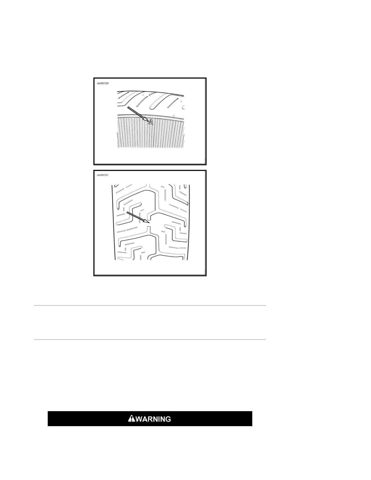
Tire Sidewall
Tread Surface
Vehicle Alignment
Isolation Mounted Engine Models
Refer to Regular Service Intervals: 2008 Touring Models. Vehicle alignment should be checked
at regular intervals. This includes whenever the rear wheel is removed and installed or when the
rear drive belt is adjusted. The stabilizer links and engine mounts should be checked for wear
according to Service Manual procedures at proper intervals.
Vehicle alignment is important. Vehicle stability is adversely affected if wheels are out of alignment.
Major alignment of the front and rear wheel is partially controlled by one stabilizer link at the top of
the engine. See a Harley Davidson dealer for this service.
Do not change stabilizer link adjustment. Changing adjustment can adversely
affect stability, which could result in death or serious injury. (00059a)
Page 21 of 49
Only a Harley Davidson dealer should perform vehicle alignment. Improper
alignment can adversely affect stability and handling, which could result in
death or serious injury. (00060a)
Shock Absorbers
Refer to Regular Service Intervals: 2008 Touring Models. Inspect shock absorbers and rubber
bushings for leaks and bushing deterioration at proper intervals.
Spark Plugs
Refer to Regular Service Intervals: 2008 Touring Models. Check the spark plugs at proper
intervals.
Do NOT pull on any electrical wires. Pulling on electrical wires may damage the
internal conductor causing high resistance, which may result in minor or
moderate injury. (00168a)
Disconnect spark plug cables from plugs by pulling on the molded connector caps. To reconnect,
simply snap-on spark plug cables to tops of spark plugs.
Refer to Ignition System: 2008 Touring Models before servicing spark plugs.
1. Check spark plug type. Only use those spark plugs specified for your model motorcycle.
2. Check spark plug gap against table specifications.
3. Always tighten to the proper torque. Spark plugs must be tightened to the torque specified
for proper heat transfer.
NOTE:
If a torque wrench is not available, tighten plugs finger tight and then tighten an additional one
quarter turn with a spark plug wrench.
Ignition
The engine in your motorcycle has been designed specifically to achieve optimum fuel economy
within exhaust emission controls. Factory programmed ignition characteristics provide maximum
engine performance and driveability.
Air Cleaner
Page 22 of 49
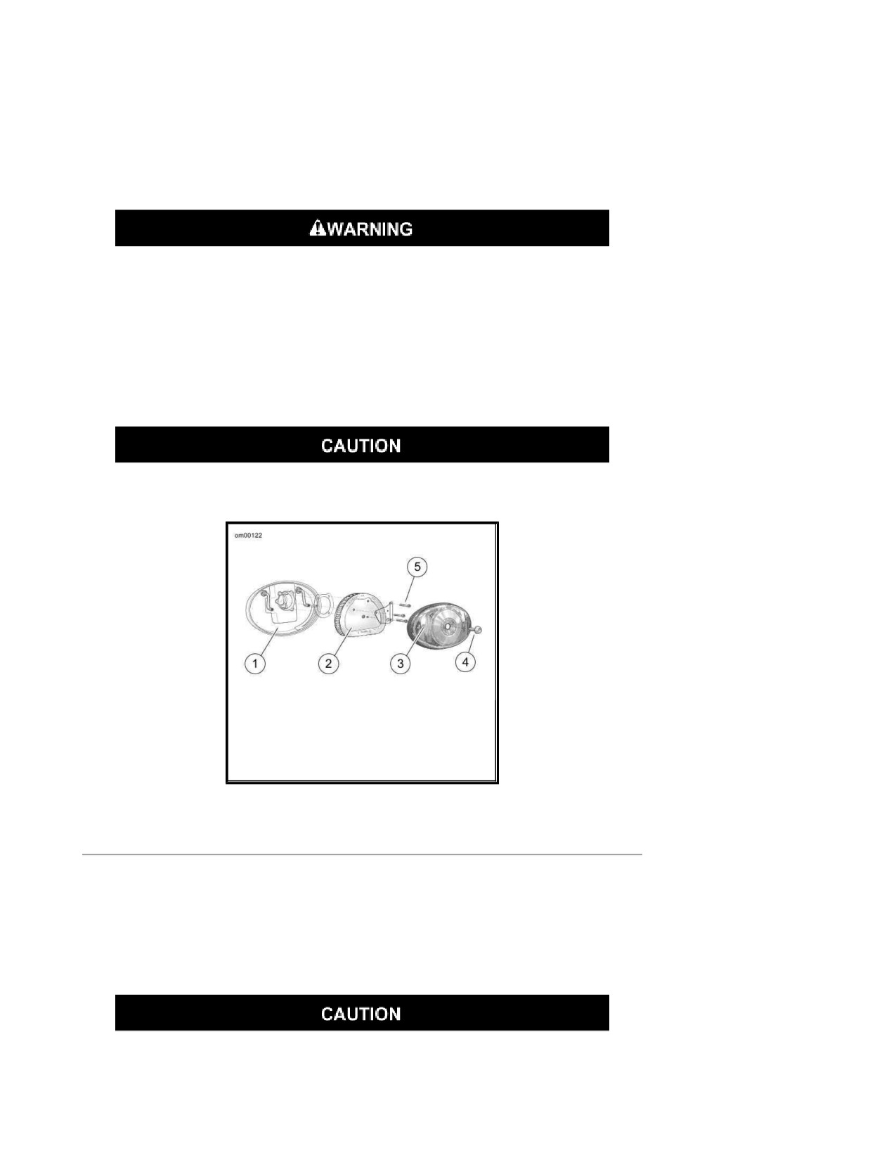
See Air Cleaner: Twin Cam Models. The engine air cleaner is a paper/wire mesh air filter element.
Refer to Regular Service Intervals: 2008 Touring Models. Remove air cleaner cover and inspect
filter element at proper intervals. Under dusty conditions, inspect more often.
The paper/wire mesh air filter element should be washed in luke warm water with a mild detergent.
Compressed air can pierce the skin and flying debris from compressed air could
cause serious eye injury. Wear safety glasses when working with compressed
air. Never use your hand to check for air leaks or to determine air flow rates.
(00061a)
Allow filter to either air dry or blow it dry, from the inside, with low pressure air.
Do not use an air cleaner filter oil on the Harley Davidson paper/wire mesh air filter
element.
Install air filter before running engine. Failure to do so can draw debris into the
engine and could result in engine damage. (00207a)
1. Backplate
2. Filter element
3. Cover
4. Cover screw
5. Screws
Air Cleaner: Twin Cam Models
Headlamp
See Headlamp Bulb: FLTR. The headlamp assembly uses replaceable quartz halogen bulb(s).
NOTE:
Refer to Bulb Chart: 2008 Touring Models and see a service manual for more details.
When replacement is required, use only the specified sealed beam unit or bulb,
available from a Harley Davidson dealer. An improper wattage sealed beam or

Page 23 of 49
bulb, can cause charging system problems. (00209a)
Never touch the quartz bulb. Fingerprints will etch the glass and decrease bulb
life. Grab the bulb with paper or a clean, dry cloth. Failure to do so could result
in bulb damage. (00210a)
Handle bulb carefully and wear eye protection. Bulb contains gas under
pressure, which, if not handled carefully, could cause serious eye injury.
(00062b)
1. Bulb
2. Tabs
Headlamp Bulb: FLTR
Headlamp Alignment: Touring Models
Check Alignment
The automatic-on headlamp feature provides increased visibility of the rider to
other motorists. Be sure headlamp is on at all times. Poor visibility of rider to
other motorists can result in death or serious injury. (00030b)
1. Verify correct front and rear tire inflation pressure. Refer to Tire Pressures: 2008 Touring
Models.
2. Place the motorcycle on a level floor or pavement in an area with minimum light.
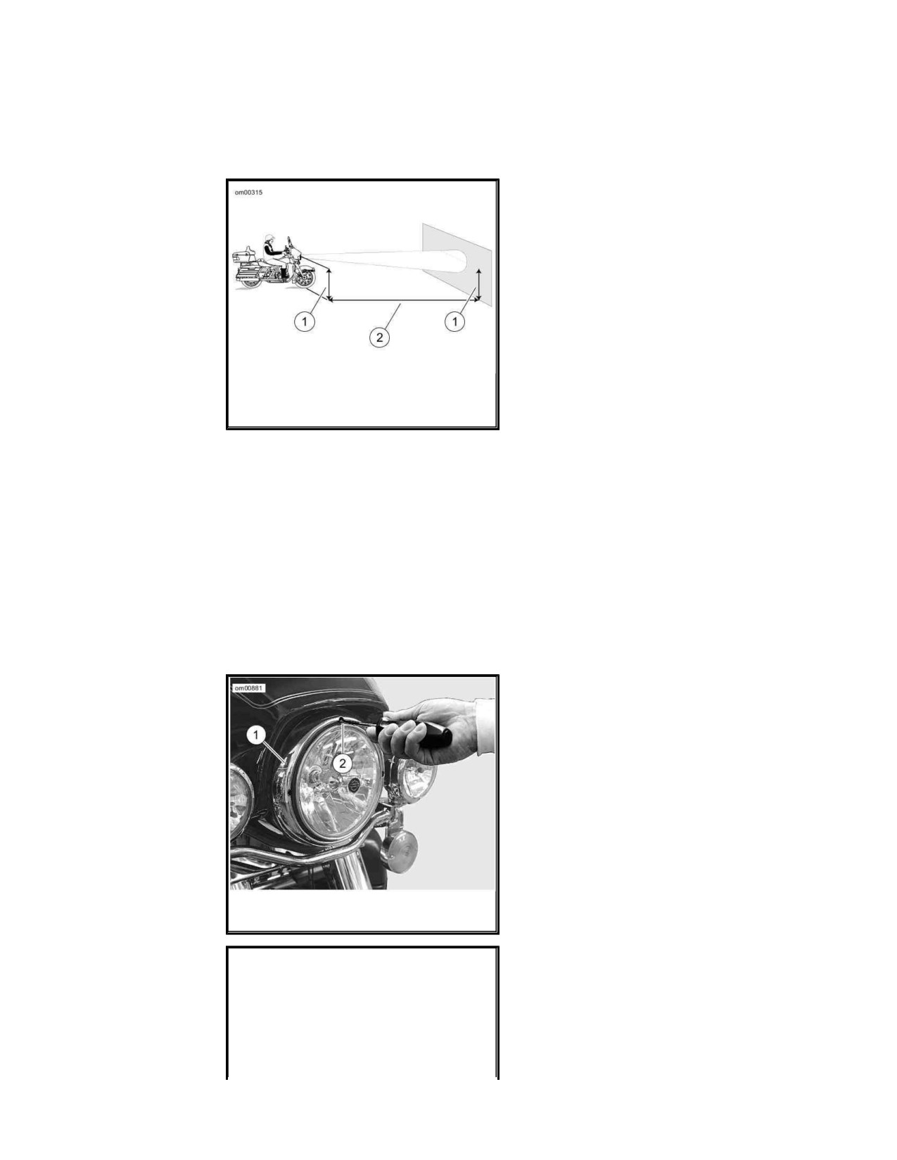
3. See Check Headlamp Alignment: Touring Models. Point the front of the motorcycle
toward a screen or wall which is 25 feet (7.6 meters) from where patch of front tire contacts
floor (i.e. - directly below front axle).
Page 24 of 49
4. Draw a horizontal line on screen or wall (dimension "A") that is exactly the same height
above the floor as the headlamp center.
5. Have a person whose weight is roughly the same as that of the principal rider sit on the
motorcycle seat. The weight of the rider will compress the vehicle suspension slightly.
1. Distance to center of headlamp
2.
25 feet (7.6 meters)
Check Headlamp Alignment: Touring
Models
6. Stand the motorcycle upright with both tires resting on the floor and with the front wheel
held in straight alignment (directly forward).
7. Turn the ignition/headlamp key switch to IGNITION. Rock the headlamp dimmer switch on
the left handlebar to HI.
8. Verify and correct headlamp adjustment if necessary.
a. Check the light beam for proper height alignment. The center of the main beam of
light should be even with the horizontal line on the screen or wall.
b. Check the light beam for proper lateral alignment. The main beam of light should be
directed straight ahead (i.e., equal area of light to right and left of center).
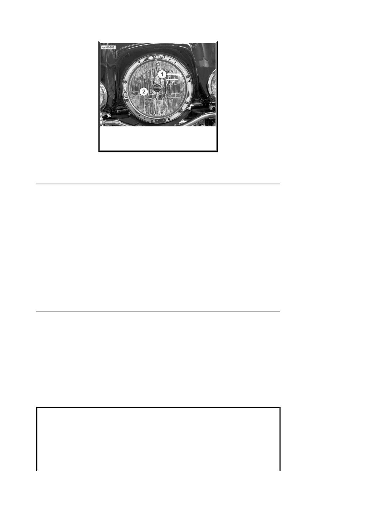
1. Headlamp door
2. Slot
Headlamp Door: 2008 Touring Models
Page 25 of 49
1. Vertical adjusting screw
2. Horizontal adjusting screw
Headlamp Adjustment: FLHT, FLHX, FLHTC,
FLHTCU, FLHR and FLHRC
Adjust FLHT/FLHR Headlamps
NOTE:
Headlamp adjustment can be performed without removing the headlamp door (chrome ring).
1. See Headlamp Door: 2008 Touring Models. Insert Phillips screwdriver between
headlamp housing and rubber gasket.
2. See Headlamp Adjustment: FLHT, FLHX, FLHTC, FLHTCU, FLHR and FLHRC. Adjust
beam.
a. Horizontal: Turn the vertical adjusting screw (1) to adjust headlamp vertically.
b. Vertical: Turn the horizontal adjusting screw (2) to adjust headlamp horizontally.
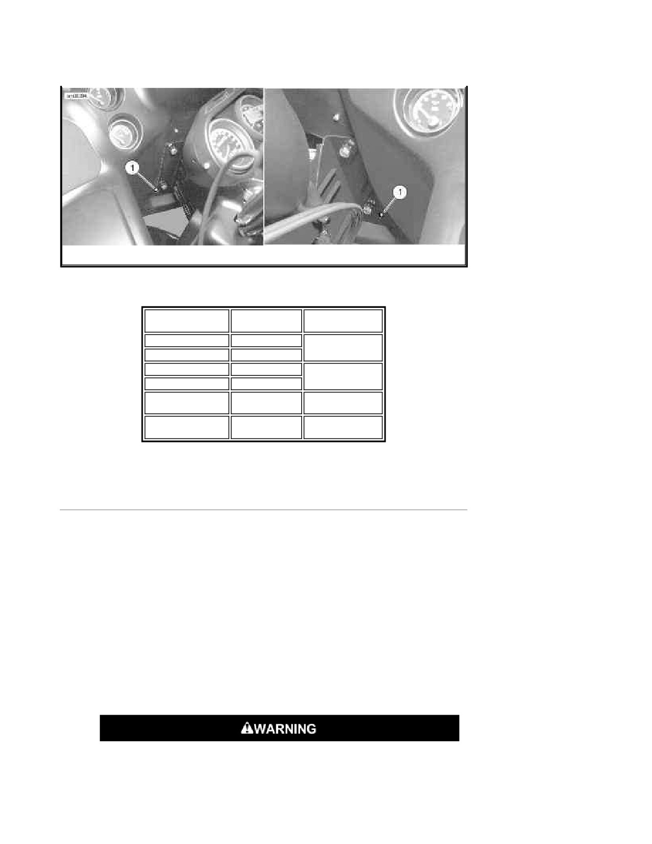
Adjust FLTR Headlamps
1. See Headlamp Adjustment: FLTR. Fit a 4.5 mm deep socket and a flexible driver to the
hex adjusters near the bottom edge of the left and right inner fairing. The adjusters pivot
the double headlamp housing around its upper mount.
2. Adjust the headlamp beam.
a. Horizontal: Turn the left or right adjuster to horizontally center the headlamp
beam.
b. Vertical: Turn both adjusters equally to adjust the headlamp vertically. Refer to
FLTR Hex Adjuster Rotation for directions to move headlamp beam.
Page 26 of 49
1. Hex adjuster
Headlamp Adjustment: FLTR
FLTR Hex Adjuster Rotation
HEX ADJUSTER
ROTATION
BEAM
MOVEMENT
Left only
clockwise
to the right
Right only
counterclockwise
Left only
counterclockwise
to the left
Right only
clockwise
Left and right
clockwise
upward
equally
Left and right
counterclockwise
downward
equally
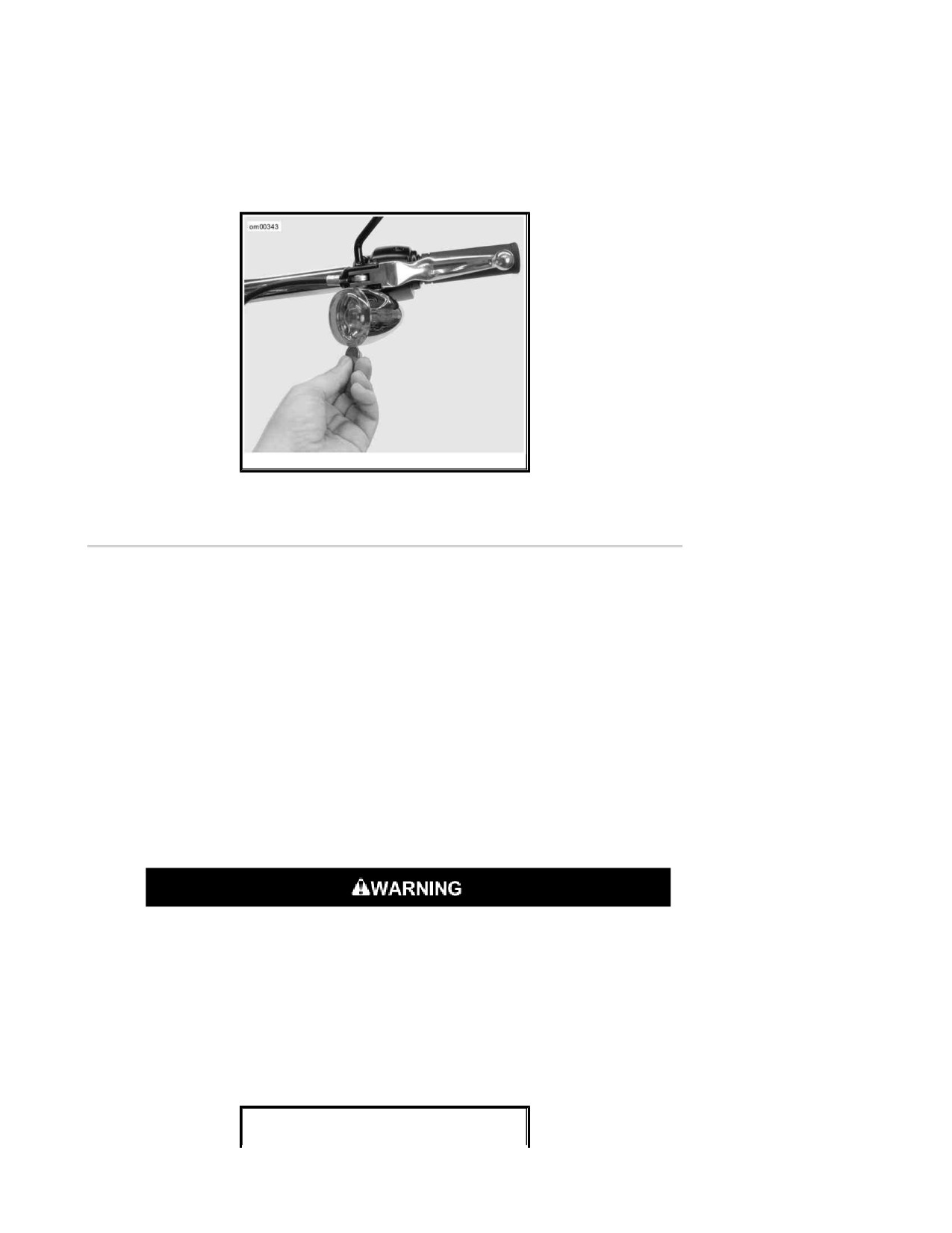
Turn Signal Bulb Replacement: Bullet Style
1. See Lens Cap Notch. Insert a coin or the blade of a small screwdriver into the notch at the
bottom of the lens cap. Carefully twist until the lens cap pops out of the lamp housing.
2. Push in bulb and rotate counterclockwise. Pull bulb from socket.
3. Inspect condition of electrical contacts in socket. If necessary, clean with a small wire brush
and electrical contact cleaner.
4. Coat base of new bulb with ELECTRICAL CONTACT GREASE 99861-90 .
5. Orient index pins on new bulb with pin guides inside bulb socket. Push bulb in and turn
clockwise to lock in place.
6. Snap lens cap back into the lamp holder. Rotate lens to position notch at bottom of lamp.
Be sure that all lights and switches operate properly before operating
motorcycle. Low visibility of rider can result in death or serious injury.
(00316a)
Page 27 of 49
7. Turn ignition on and test for proper turn signal operation.
NOTE:
If the turn signal or running lamp will not light after replacing a bulb, check the wiring, the ground
at the socket and/or the switch.
Lens Cap Notch
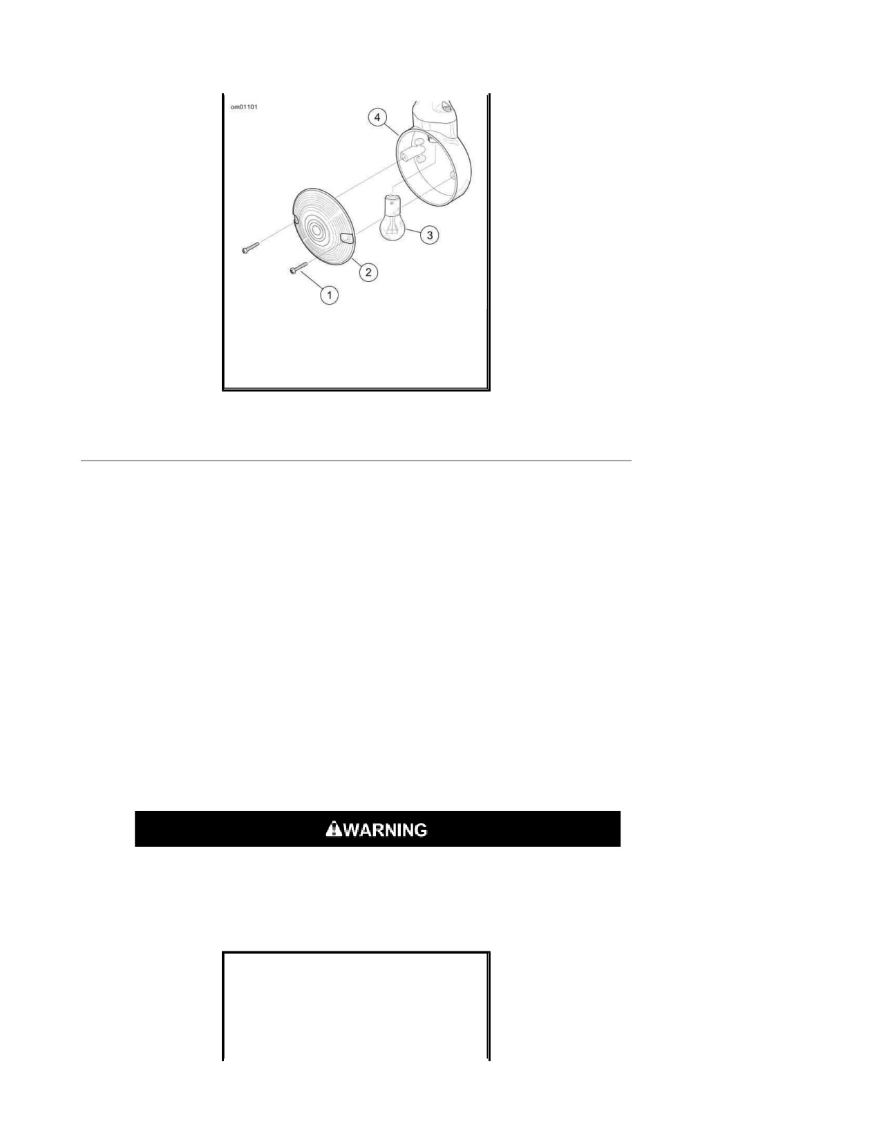
Turn Signal Bulb Replacement: Flat Lens Style
1. See Turn Signal Lamp Assembly: Flat Lens Style. Remove two screws to release lens
from lamp housing.
2. Push in bulb and rotate counterclockwise to remove bulb from socket.
3. Inspect condition of electrical contacts in socket. If necessary, clean with a small wire brush
and electrical contact cleaner.
4. Liberally apply dielectric grease to contacts in socket and at bottom of new bulb.
5. Orient index pins on new bulb with pin guides inside bulb socket.
6. Push bulb in and turn clockwise to lock in place.
7. Seat lens in lamp and install two screws.
Be sure that all lights and switches operate properly before operating
motorcycle. Low visibility of rider can result in death or serious injury.
(00316a)
8. Turn ignition on and test for proper turn signal operation.
NOTE:
If the turn signal or running lamp will not light after replacing a bulb, check the wiring, the ground
at the socket and/or the switch.
Page 28 of 49
1. Screws (2)
2. Lens
3. Bulb
4. Lamp housing
Turn Signal Lamp Assembly: Flat Lens
Style
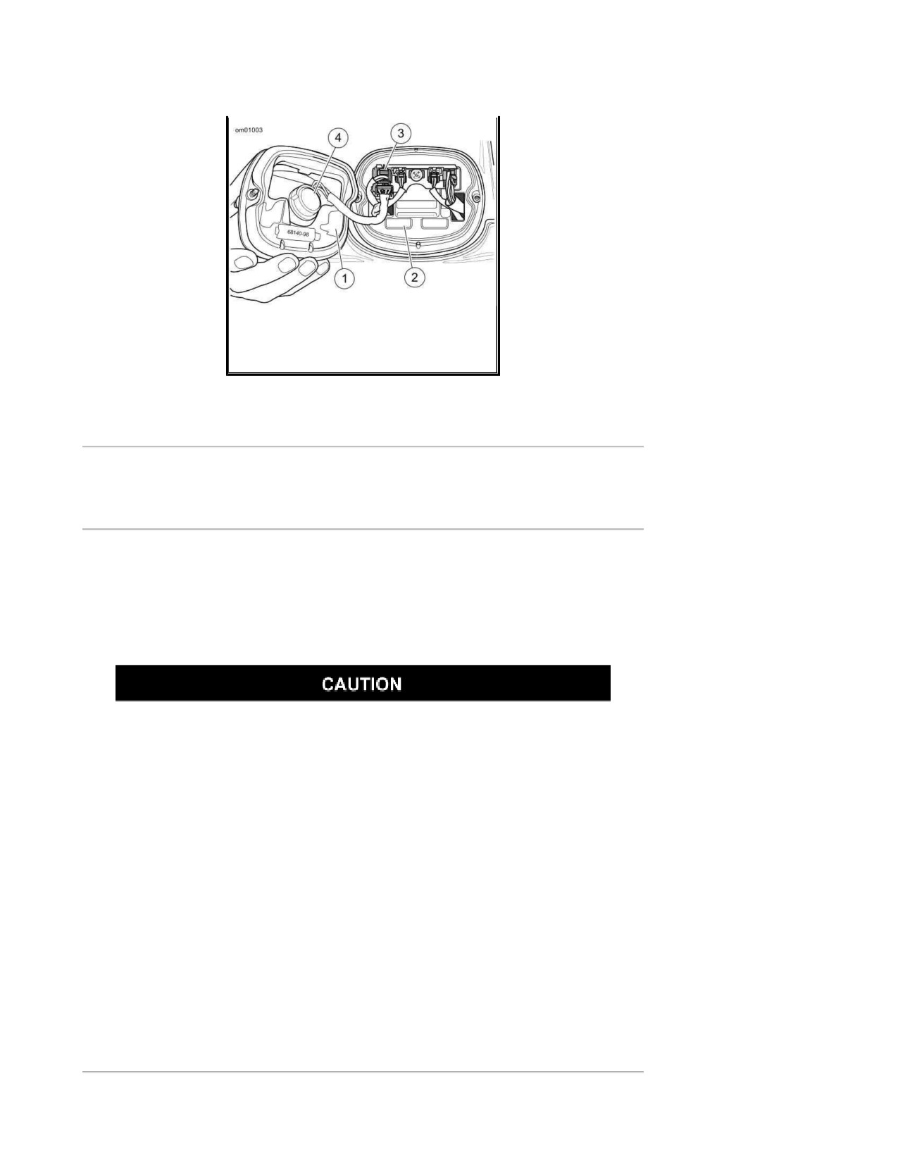
Tail Lamp Bulb Replacement: Standard Style
1. See Tail Lamp Assembly: Standard Style. Make certain ignition switch is turned off.
2. Remove two screws and lens from base.
NOTE:
For ease of bulb removal, the 4-Pin multilock connector can be removed from circuit board.
3. Remove (pull) bulb assembly from lens. Remove bulb from socket.
4. Coat base of new bulb with ELECTRICAL CONTACT GREASE (Part No. 99861-90). Install
new bulb in socket.
5. Install (push) bulb assembly to lens.
6. If removed connect 4-Pin multilock connector to circuit board.
7. Install lens to base with two screws. Tighten screws to 20-24 in-lbs (2.3-2.7 Nm).
Be sure that all lights and switches operate properly before operating
motorcycle. Low visibility of rider can result in death or serious injury.
(00316a)
8. Turn ignition on and test for proper tail lamp operation.
Page 29 of 49
1. Lens
2. Base
3.
4-pin multilock connector
4.
Bulb assembly
Tail Lamp Assembly: Standard Style
Alternator/Voltage Regulator
Charging Rate
The alternator output is controlled and changed to direct current by the voltage regulator.
The voltage regulator increases charging rate when battery is low or lamps are lit.
The voltage regulator decreases charging rate when battery charge is up.
It is possible to overload your motorcycle's charging system by adding too
many electrical accessories. If your combined electrical accessories operating
at any one time consume more electrical current than your vehicle's charging
system can produce, the electrical consumption can discharge the battery and
cause vehicle electrical system damage. See a Harley Davidson dealer for
advice about the amount of current consumed by additional electrical
accessories, or for necessary wiring changes. (00211b)
A battery voltage LED in the instruments will light up when voltage is either too low or too high.
NOTES:
This unit requires no interval attention. If any electrical system trouble is experienced that
might be traceable to the alternator or voltage regulator, the motorcycle should be taken to
a Harley Davidson dealer who has the necessary electrical testing equipment to give the
required attention.
For model specific information regarding the voltage regulator, refer to the appropriate
Service Manual or see a Harley Davidson dealer.
Battery: General
Page 30 of 49
Type
Your motorcycle uses a permanently sealed, maintenance-free, lead/calcium and sulfuric acid
battery. All batteries are shipped precharged and ready to be put into service. Do not attempt to
open the battery for any reason.
Antidotes for Battery Acid
CONTACT
TREATMENT
External
Flush with water.
Internal
Drink large quantities of milk or water,
followed by milk of magnesia, vegetable oil or
beaten eggs. Get immediate medical
attention.
Eyes
Flush with water. Get immediate medical
attention.
Batteries contain sulfuric acid, which could cause severe burns to eyes and
skin. Wear a protective face shield, rubberized gloves and protective clothing
when working with batteries. KEEP BATTERIES AWAY FROM CHILDREN.
(00063a)
Explosive hydrogen gas, which escapes during charging, could cause death or
serious injury. Charge battery in a well-ventilated area. Keep open flames,
electrical sparks and smoking materials away from battery at all times. KEEP
BATTERIES AWAY FROM CHILDREN. (00065a)
Batteries, battery posts, terminals and related accessories contain lead and
lead compounds, and other chemicals known to the State of California to cause
cancer, and birth defects or other reproductive harm. Wash hands after
handling. (00019e)
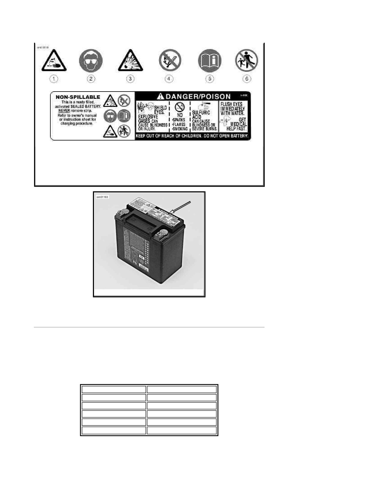
Never remove warning label attached to top of battery. Failure to read and
understand all precautions contained in warning, could result in death or
serious injury. (00064a)
Page 31 of 49
1. Contents are corrosive
2. Wear safety glasses
3. Contents are explosive
4. Keep flames away
5. Read instructions
6. Keep away from children
Battery Warning Label
Battery Warning Label
Voltmeter Test
Refer to Voltmeter Test. The voltmeter test provides a general indicator of battery condition.
Check the voltage of the battery to verify that it is in a 100 percent fully charged condition. If the
open circuit (disconnected) voltage reading is below 12.6V, charge the battery and then re-check
the voltage after the battery has set for one to two hours.
Voltmeter Test
READING IN VOLTS
PERCENT OF CHARGE
12.7
100
12.6
75
12.3
50
12.0
25
11.8
0
Page 32 of 49
Cleaning and Inspection
Battery top must be clean and dry. Dirt and electrolyte on top of the battery can cause battery to
self-discharge.
1. Clean battery top.
2. Clean cable connectors and battery terminals using a wire brush or fine grit sandpaper to
remove any oxidation.
3. Inspect and clean the battery screws, clamps and cables. Check for breakage, loose
connections and corrosion.
4. Check the battery posts for melting or damage caused by overtightening.
5. Inspect the battery for discoloration, a raised top or a warped or distorted case. This might
indicate that the battery has been frozen, overheated or overcharged.
6. Inspect the battery case for cracks or leaks.
Charging
Never charge a battery without first reviewing the instructions for the charger being used. In
addition to the manufacturer's instructions, follow these general safety precautions.
Charge the battery if any of the following conditions exist:
Vehicle lamps appear dim.
Electric starter sounds weak.
Battery has not been used for an extended period of time.
Explosive hydrogen gas, which escapes during charging, could cause death or
serious injury. Charge battery in a well-ventilated area. Keep open flames,
electrical sparks and smoking materials away from battery at all times. KEEP
BATTERIES AWAY FROM CHILDREN. (00065a)
Batteries contain sulfuric acid, which could cause severe burns to eyes and
skin. Wear a protective face shield, rubberized gloves and protective clothing
when working with batteries. KEEP BATTERIES AWAY FROM CHILDREN.
(00063a)
1. Perform a voltmeter test to determine the state of charge. If battery needs to be charged,
proceed to the next step.
2. Place the battery on a level surface.
Page 33 of 49
Unplug or turn OFF battery charger before connecting charger cables to
battery. Connecting cables with charger ON can cause a spark and battery
explosion, which could result in death or serious injury. (00066a)
Connect positive (+) battery cable first. If positive (+) cable should contact
ground with negative (-) cable connected, the resulting sparks can cause a
battery explosion, which could result in death or serious injury. (00068a)
Disconnect negative (-) battery cable first. If positive (+) cable should contact
ground with negative (-) cable connected, the resulting sparks can cause a
battery explosion, which could result in death or serious injury. (00049a)
Do not reverse the charger connections described in the following steps or the
charging system of the motorcycle could be damaged. (00214a)
NOTES:
The figures listed in the Amp-hour table assume that the battery is charging at room
temperature. If warmer than room temperature, use a slightly shorter charging
time. If colder, use a slightly longer charging time.
The use of constant current chargers to charge sealed maintenance free batteries is
not recommended. Any overcharge will cause dry-out and premature battery failure.
If a constant current charger is the only type available, do not exceed the charge
times listed in 28 Amp-Hour Battery Charging Rate/Times and do not continue
charging the battery if it gets hot. When charging, never exceed 15 volts.
3. Connect the red battery charger lead to positive (+) terminal of the battery.
4. Connect the black battery charger lead to negative (-) terminal of the battery.
NOTE:
If the battery is still in the vehicle, connect the negative lead to the chassis ground. Make
sure that the ignition and all electrical accessories are turned off.
5. Step away from the battery and turn on the charger.
Unplug or turn OFF battery charger before disconnecting charger cables from
battery. Disconnecting clamps with charger ON can cause a spark and battery
explosion, which could result in death or serious injury. (00067a)
6. After the battery is fully charged, turn OFF the charger and disconnect the black battery
charger lead to the negative (-) terminal of the battery.
7. Disconnect the red battery charger lead to the positive (+) terminal of the battery.
8. Mark the charging date on the battery.
Page 34 of 49
28 Amp-Hour Battery Charging Rate/Times
READING
PERCENT
3 AMP
6 AMP
10 AMP
20 AMP
(VOLTS)
OF CHARGE
CHARGER
CHARGER
CHARGER
CHARGER
12.7
100
-
-
-
-
12.6
75
2.5 hours
1.25 hours
45 minutes
25 minutes
12.3
50
5 hours
2.5 hours
1.5 hours
50 minutes
12.0
25
7.5 hours
3.75 hours
2.25 hours
70 minutes
11.8
0
10 hours
5 hours
3 hours
1.5 hours
Storage
Turn engine over a few times to be sure there is no oil in the crankcase and
that all oil has been pumped back into the oil tank. Stop engine and re-check oil
level. Failure to do so can result in engine damage. (00071a)
Do not allow battery to completely discharge. The electrolyte in a discharged
battery will freeze. The more discharged a battery is, the more easily it can
freeze and crack the battery case. (00218a)
If the motorcycle will not be operated for several months, such as during the winter season, remove
the battery from the motorcycle and fully charge.
If the motorcycle is to be stored with the battery installed, it will be necessary to connect a battery
tender to maintain charge. See an authorized dealer for more information.
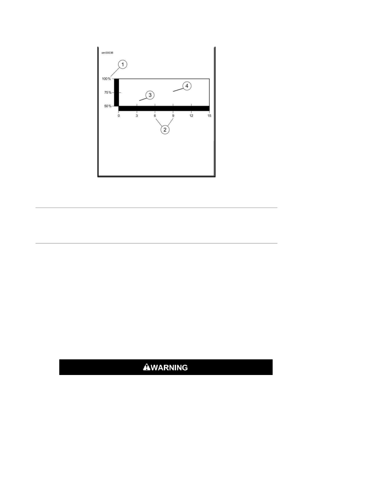
Self-discharge is a normal condition and occurs continuously. The rate of self-discharge depends on
the ambient temperature and the battery's state of charge.
Batteries discharge at a faster rate at higher ambient temperatures.
To reduce the self-discharge rate, store battery in a cool (not freezing), dry place.
Charge the battery every month if stored at temperatures below 60° F 16° C .
Charge the battery more frequently if stored in a warm area above 60° F 16° C .
Page 35 of 49
1. Capacity
2. Months of stand
3. Measured at 105° F (40° C)
4. Measured at 77° F (25° C)
Effective Rate of Temperature on Battery
Self-discharging Rate
Battery: Touring Models
Disconnection and Removal
1. Remove seat.
NOTE:
The ECM caddy has an opening in the front right corner allowing access to the negative
battery terminal.
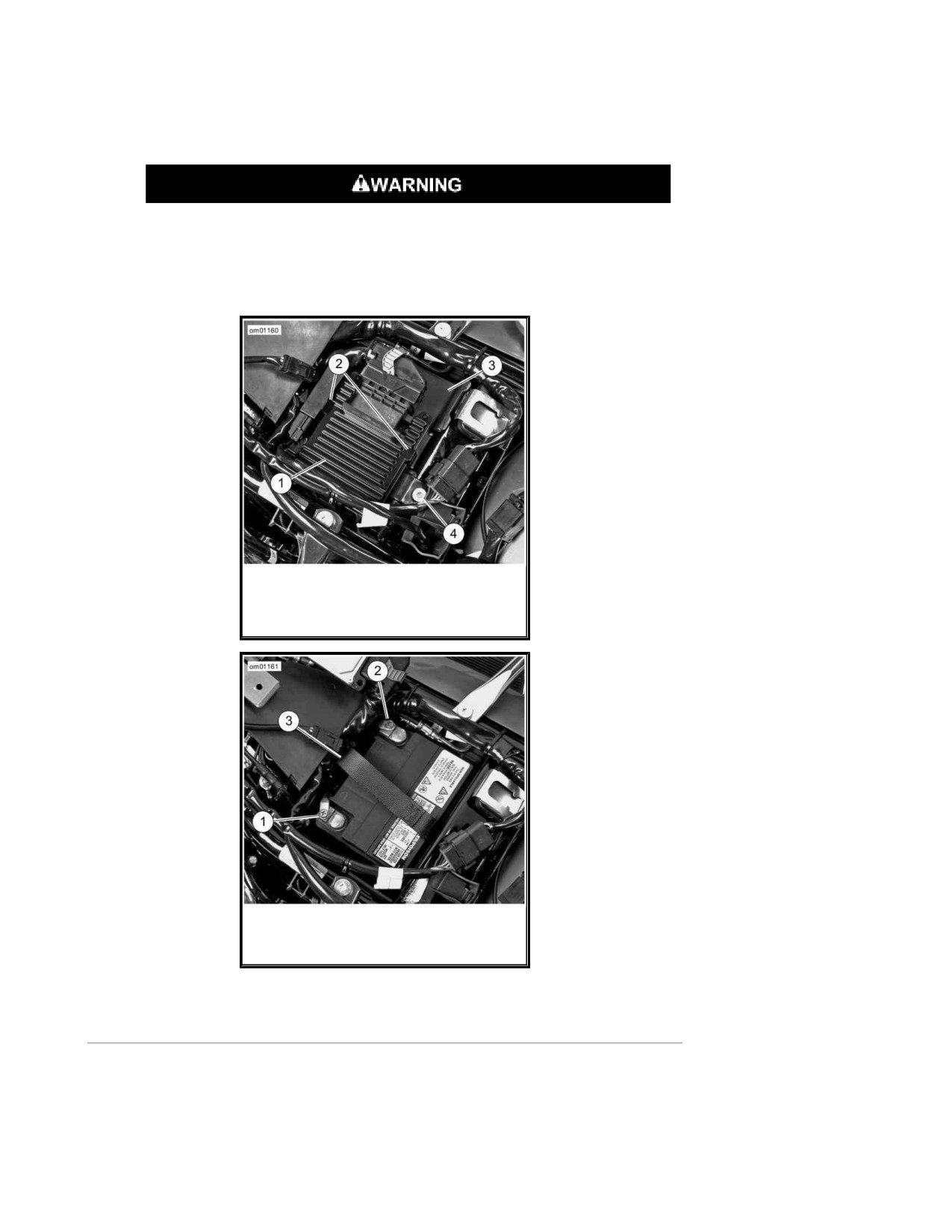
2. See ECM Caddy: Touring Models. Press latches (2) away from the ECM (1) and detach
from ECM caddy (3).
3. Remove fastener (4) from rear of ECM caddy.
4. Remove ECM caddy from battery compartment.
Disconnect negative (-) battery cable first. If positive (+) cable should contact
ground with negative (-) cable connected, the resulting sparks can cause a
battery explosion, which could result in death or serious injury. (00049a)
5. See Battery Compartment: Touring Models. Unthread bolt and remove battery negative
cable (black) from battery negative (-) terminal.
6. Unthread bolt and remove battery positive cable (red) from battery positive (+) terminal.
7. Pull up on strap to lift battery out from compartment.
Installation and Connection
Page 36 of 49
Connect the cables to the correct battery terminals. Failure to do so could
result in damage to the motorcycle electrical system. (00215a)
Connect positive (+) battery cable first. If positive (+) cable should contact
ground with negative (-) cable connected, the resulting sparks can cause a
battery explosion, which could result in death or serious injury. (00068a)
Do not allow positive (+) battery cable to contact ground with negative (-)
cable connected. Resulting sparks can cause a battery explosion, which could
result in death or serious injury. (00069a)
NOTE:
Make sure strap is inside compartment under battery. The strap handle should remain outside the
compartment.
1. See Battery Compartment: Touring Models. Place the fully charged battery into
compartment with terminals toward the front of the vehicle. Lay strap handle over top of
battery.
Do not over-tighten bolts on battery terminals. Use recommended torque
values. Over-tightening battery terminal bolts could result in damage to battery
terminals. (00216a)
2. Insert bolt through battery positive cable (+) (red) into threaded hole of battery positive (+)
terminal.
3. Tighten bolt to 60-96 in-lbs (6.8-10.8 Nm).
4. Insert bolt through battery negative cable (black) into threaded hole of battery negative (-)
terminal.
5. Tighten bolt to 60-96 in-lbs (6.8-10.8 Nm).
Keep battery clean and lightly coat terminals with petroleum jelly to prevent
corrosion. Failure to do so could result in damage to battery terminals.
(00217a)
6. Apply a light coat of petroleum jelly or corrosion retardant material to both battery
terminals.
7. See ECM Caddy: Touring Models. Install ECM caddy over battery compartment. Tighten
fastener to 15-20 ft-lbs (20-27 Nm).
Page 37 of 49
8. Align ECM with latches on caddy. Snap ECM into place and slide to left side of vehicle until
ECM rests against bracket on left side of caddy and rests on guide pins. The negative battery
terminal should be visible through the caddy.
After installing seat, pull upward on seat to be sure it is locked in position.
While riding, a loose seat can shift causing loss of control, which could result in
death or serious injury. (00070b)
9. Install seat.
1. Electronic control module (ECM)
2. Latches
3. ECM caddy
4. ECM caddy fastener
ECM Caddy: Touring Models
1. Positive terminal
2. Negative terminal
3. Battery strap
Battery Compartment: Touring Models
Jump Starting
Harley Davidson does not recommend jump-starting a motorcycle. However, there may be
circumstances when it is necessary to do so. Therefore, we suggest jump-starting be performed as
follows:
Page 38 of 49
Be sure jumper cables touch only appropriate battery terminals or ground.
Allowing jumper cables to touch each other can result in sparks and a battery
explosion, which could result in death or serious injury. (00072a)
Explosive hydrogen gas, which escapes during charging, could cause death or
serious injury. Charge battery in a well-ventilated area. Keep open flames,
electrical sparks and smoking materials away from battery at all times. KEEP
BATTERIES AWAY FROM CHILDREN. (00065a)
Harley Davidson motorcycles have a 12 Volt battery. Be sure the booster
vehicle has a 12 Volt system. Failure to do so could result in vehicle damage.
(00220a)
NOTE:
This procedure presumes the BOOSTER battery is in another vehicle.
1. Turn off all unnecessary lamps and accessories.
Positive Cable
2. See Jump Start Cable Connections. Connect one end of a jumper cable to the
DISCHARGED battery positive (+) terminal (1).
3. Connect the other end of the same cable to the BOOSTER battery positive (+) terminal (2).
Negative Cable
Do not connect negative (-) cable to or near the discharged battery negative (-)
terminal. Doing so could cause a spark and explosion, which could result in
death or serious injury. (00073a)
4. Connect one end of a jumper cable to the BOOSTER battery negative (-) terminal (3).
Do not connect the negative (-) cable to painted or chrome parts. Doing so
could result in discoloration at the attachment point. (00221a)
5. Connect other end of the same cable (4) to a safe ground, (away from the DISCHARGED
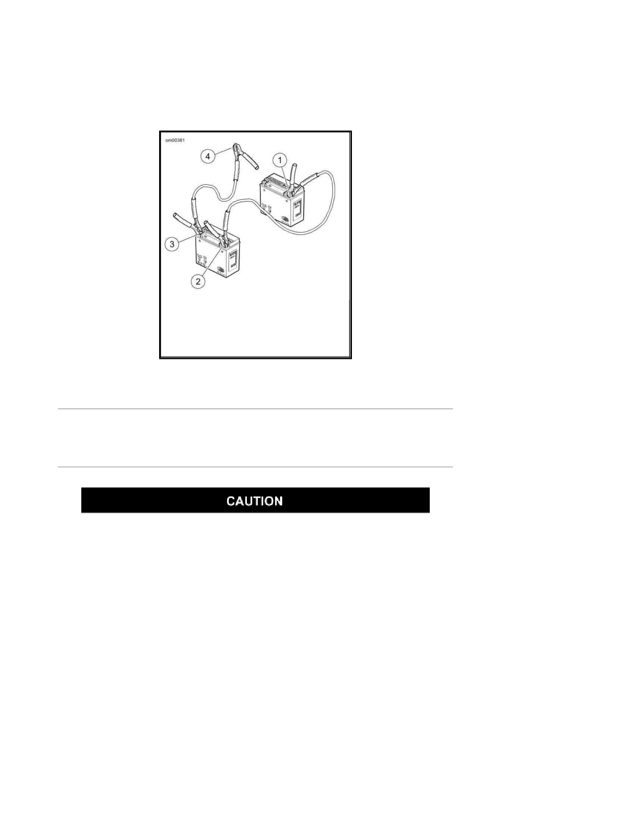
Page 39 of 49
battery).
6. Start motorcycle.
7. Disconnect cables in reverse order of steps 2, 3, 4, 5. That is: steps 5, 4, 3, 2.
1. Discharged battery positive (+)
terminal
2. Booster battery positive (+) terminal
3. Booster battery negative (-) terminal
4. Ground
Jump Start Cable Connections
Electrical Protection: Touring Models
System Fuse Removal
Do not skip any steps for fuse replacement. Skipping fuse replacement steps
can result in damage to the sound system and/or other motorcycle systems.
(00223a)
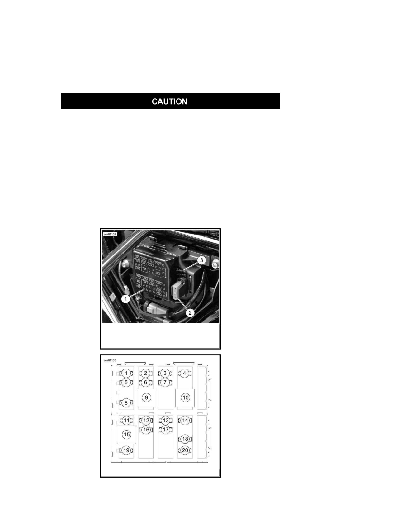
Fuses are located under left side cover.
For electrical problems, it is best to see a Harley Davidson dealer who has necessary parts and
equipment to perform electrical services.
NOTE:
See Left Side Cover Removed: Touring Models. Removal of side covers during electrical service
requires no tools. Gently pull side cover to remove. Align barbed studs on side cover with grommets
in frame and push to install.
1. Place the ignition/headlamp key switch in the OFF position.
2. Remove left saddlebag and side cover.
3. See Left Side Cover Removed: Touring Models. Press latch on bottom of fuse block
cover and swing bottom of the cover out. Remove the cover.
Page 40 of 49
NOTE:
The fuse block cover has a fuse puller attachment that may be used to remove fuses.
4. See Fuses: Touring Models and refer to Fuses: Touring Models. Remove fuse and
inspect the element.
Always use replacement fuses that are of the correct type and amperage
rating. Use of incorrect fuses can result in damage to electrical systems.
(00222a)
5. Replace the fuse if the element is burned or broken.
NOTE:
Automotive type ATO fuses are used for replacements. Two spare fuses can be found in the
fuse block.
6. Insert the top of the fuse block cover in upper retainer and press bottom of cover to snap
into place.
7. Install left side cover and saddlebag.
1. Fuse block cover
2. Maxi-fuse
3. Fuse puller
Left Side Cover Removed: Touring Models
Fuses: Touring Models
Page 41 of 49
Fuses: Touring Models
ITEM
FUSE
ITEM
FUSE
ITEM
FUSE
ITEM
FUSE
1
Brake (15 amp)
2
Accessory (15
3
P&A (15 amp)
4
Radio power (15
amp)
amp)
5
Radio memory
6
Battery (15 amp)
7
ECM power (15
8
Fuel pump (15
(15 amp)
amp)
amp)
9
System relay
10
Start relay
11
P&A ignition
12
Instruments (15
(2A max)
amp)
13
Ignition (15
14
Engine control
15
Brake relay
16
Headlamp (15
amp)
(15 amp)
amp)
17
Lights (15 amp)
18
Spare (15 amp)
19
ABS (30 amp)
20
Spare (30 amp)
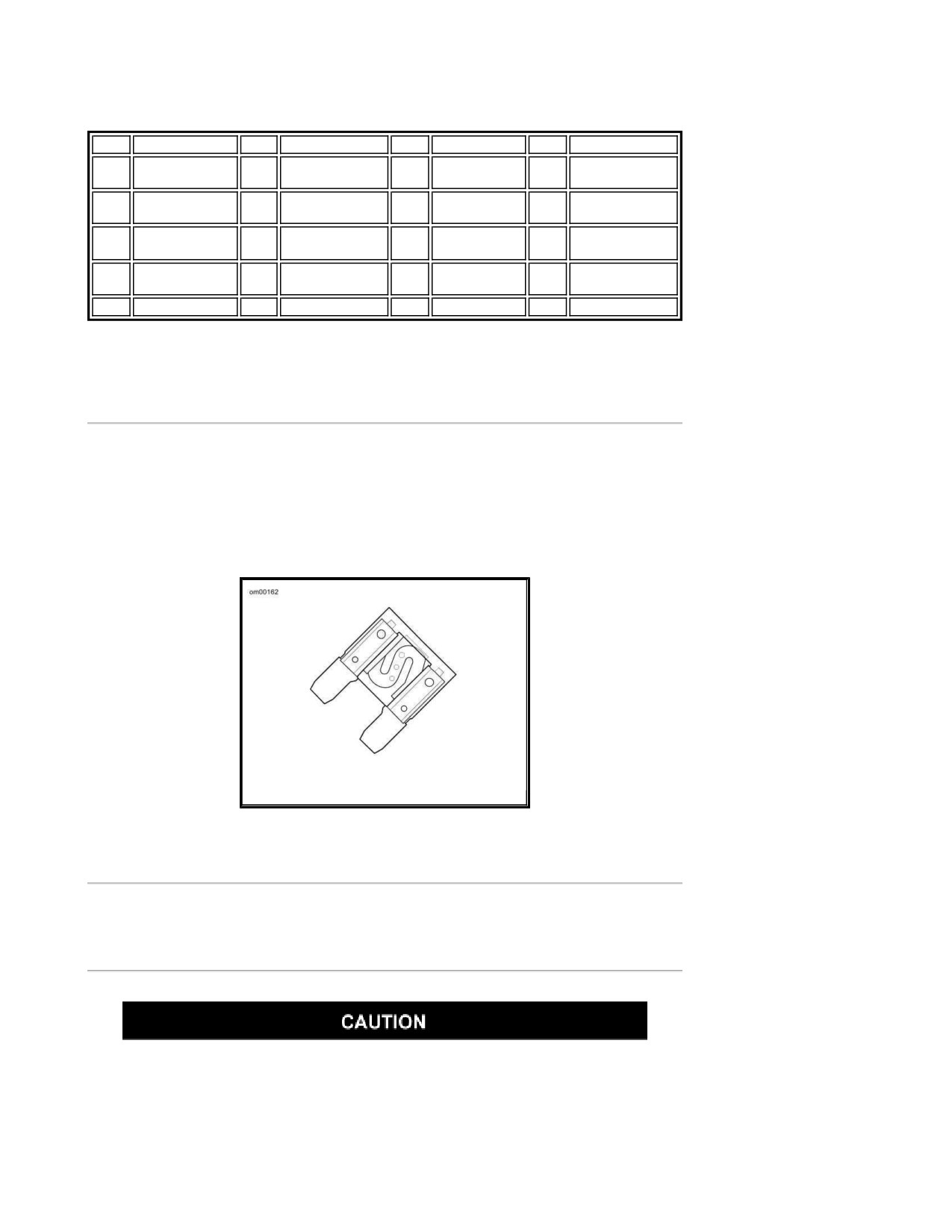
Maxi-Fuse
See Maxi-Fuse. A 40 amp maxi-fuse is located at the right side of the fuse block. The maxi-fuse
protects the electrical components in the vehicle.
NOTE:
Removal of the maxi-fuse will disable all systems except the starter motor/solenoid.
Maxi-Fuse
Seat: FLHT
Removal
Detach passenger seat strap before removing seat. Failure to do so can result
in damage to rear fender paint. (00225a)
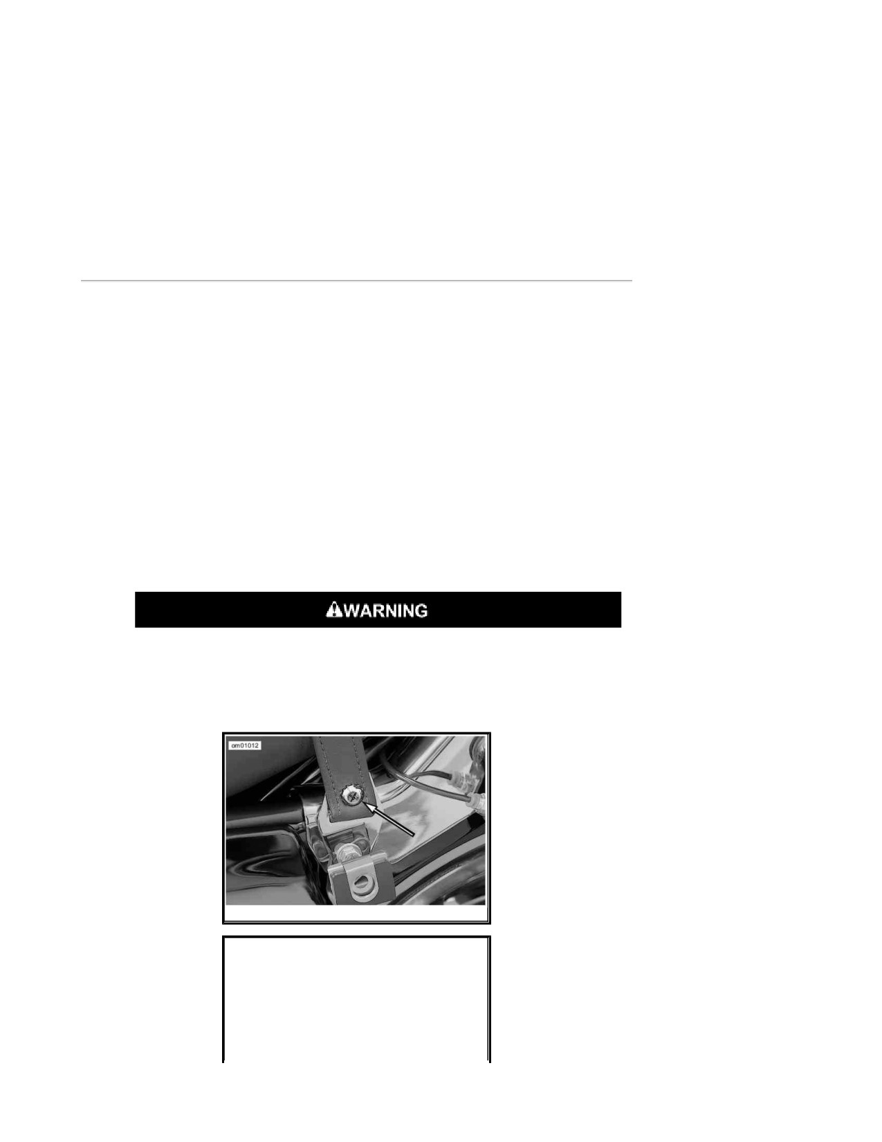
1. See Seat Strap Bracket Screw (FLHT/C/U). Open left saddlebag cover and remove
fastener from seat strap bracket.
Page 42 of 49
2. Pull upward on strap to free it from slot in bracket. Move passenger seat strap to side of
seat.
3. Remove fastener to detach seat mounting bracket from top of rear fender.
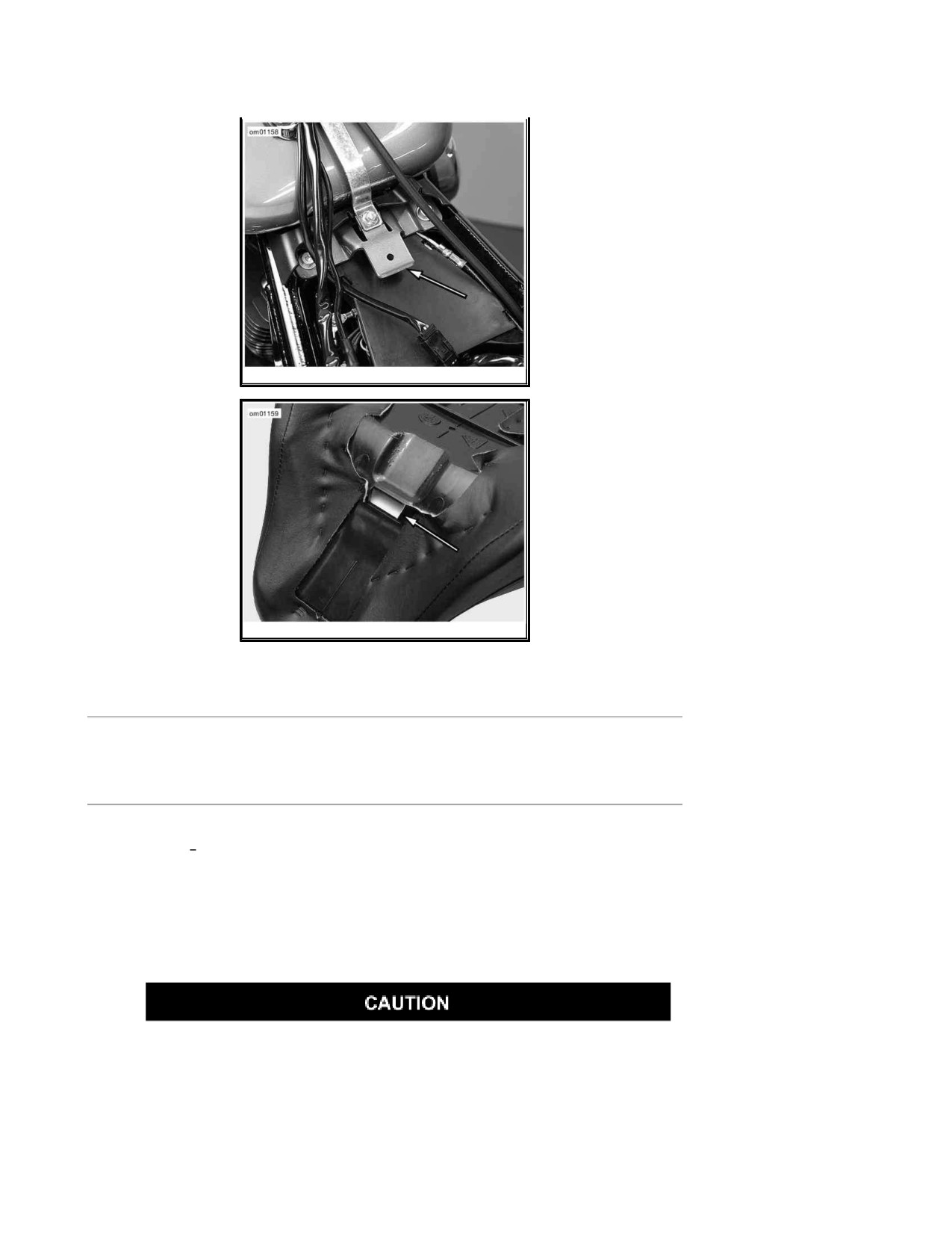
4. See Seat Tongue: Touring Models. Push seat rearward to free tongue from slot in seat.
5. Detach seat from frame.
Installation
1. See Seat Mounting Slot: Touring Models. Place seat on frame backbone.
2. See Seat Tongue: Touring Models. Firmly push front of seat downward and rearward until
tongue engages slot in frame backbone.
3. Push seat forward until rear fender seat retention nut is centered in hole of mounting
bracket.
4. Install seat mounting fastener. Tighten to 20-40 in-lbs (2.3-4.5 Nm).
NOTE:
If the seat retention nut is damaged or lost, see service manual for instructions.
5. See Seat Strap Bracket Screw (FLHT/C/U). Install end of seat strap in slot of seat strap
bracket. Install seat strap bracket fastener. Tighten to 48-72 in-lbs (5.4-8.1 Nm).
After installing seat, pull upward on seat to be sure it is locked in position.
While riding, a loose seat can shift causing loss of control, which could result in
death or serious injury. (00070b)
6. Pull up on seat to verify that it is properly secured.
Seat Strap Bracket Screw (FLHT/C/U)
Page 43 of 49
Seat Tongue: Touring Models
Seat Mounting Slot: Touring Models
Seat: FLHTC/U
Removal
1. See Tour-Pak. Open Tour-Pak to move passenger seat backrest out of the way.
NOTE:
The Tour-Pak must be positioned to the rear to gain access to the seat mounting bracket
screw. If the Tour-Pak is in the forward position, remove Tour-Pak and install in rearward
position.
Detach passenger seat strap before removing seat. Failure to do so can result
in damage to rear fender paint. (00225a)
2. See Seat Strap Bracket Screw (FLHT/C/U). Open left saddlebag cover and remove seat
strap bracket fastener.
3. Pull upward on strap to free it from slot in bracket.
Page 44 of 49
4. Move passenger seat strap to side of seat.
5. Remove fastener to detach seat mounting bracket from top of rear fender.
6. To protect finish of Tour-Pak, cover rear seat mounting bracket with palm of hand.
7. See Seat Tongue: Touring Models. While pushing seat forward, raise rear of seat until
bracket clears top of Tour-Pak. Push seat rearward slightly to free tongue from slot in seat.
8. Remove seat from frame.
Installation
1. See Seat Mounting Slot: Touring Models. Place seat on frame backbone.
2. To protect finish of Tour-Pak, cover rear seat mounting bracket with palm of hand.
3. While raising rear of seat approximately 3 in. 76.2 mm , use other hand to firmly push front
of seat downward and rearward until tongue engages slot in seat.
4. Push seat forward until rear fender seat retention nut is centered in hole of mounting
bracket.
5. Install seat mounting fastener. Tighten to 20-40 in-lbs (2.3-4.5 Nm).
NOTE:
If the seat retention nut is damaged or lost, see service manual for instructions.
After installing seat, pull upward on seat to be sure it is locked in position.
While riding, a loose seat can shift causing loss of control, which could result in
death or serious injury. (00070b)
6. Pull up on seat to verify that it is properly secured, front and rear.
7. See Seat Strap Bracket Screw (FLHT/C/U). Install end of seat strap in slot of seat strap
bracket. Install seat strap bracket fastener. Tighten to 48-72 in-lbs (5.4-8.1 Nm).
Seat: FLHR/FLHRC
Removal
1. Remove right saddlebag.
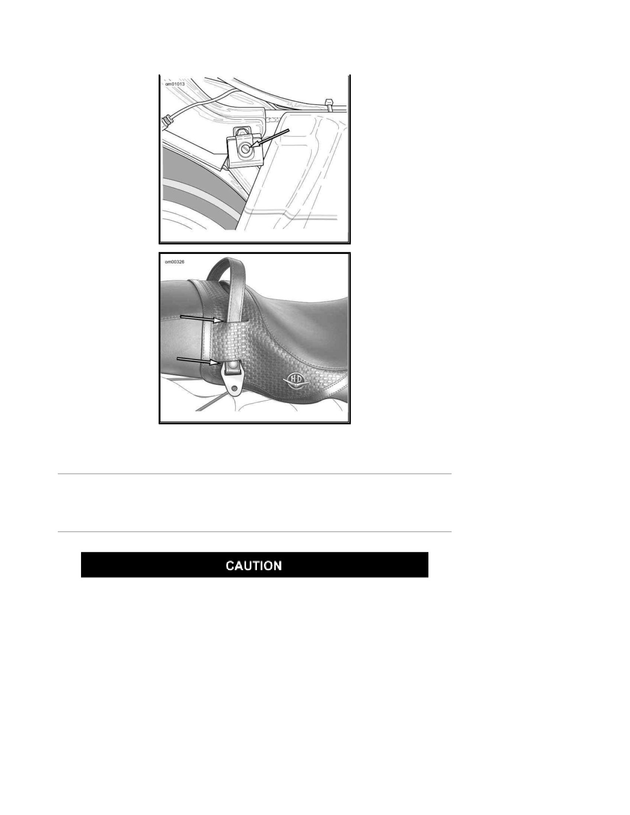
2. See Front Saddle Bracket. Remove bracket bolt with the flat washer that secures seat
strap and bracket. Then remove passenger seat strap and saddlebag front mounting bracket
from chrome frame tube cover.
Page 45 of 49
3. See Strap Slots: FLHRC. On FLHRC models, the seat strap is routed through slots in the
seat. Carefully pull passenger seat strap through slots to remove.
4. Place seat strap on opposite side of vehicle.
5. Remove fastener to detach seat mounting bracket from top of rear fender.
6. Push seat rearward to free tongue from the slot in the seat.
7. Remove seat from frame.
Installation
1. See Seat Mounting Slot: Touring Models. Place seat on frame backbone.
2. Firmly push front of seat downward and rearward until tongue engages slot in seat.
3. Push seat forward until rear fender seat retention nut is centered in hole of mounting
bracket.
4. Install seat mounting fastener. Tighten to 20-40 in-lbs (2.3-4.5 Nm).
NOTE:
If the seat retention nut is damaged or lost, see service manual for instructions.
After installing seat, pull upward on seat to be sure it is locked in position.
While riding, a loose seat can shift causing loss of control, which could result in
death or serious injury. (00070b)
5. Pull up on seat to verify that it is properly secured, front and rear.
6. See Strap Slots: FLHRC. On FLHRC models, route free end of passenger seat strap to left
side of vehicle through slots in the seat.
7. Insert bolt with flat washer through passenger seat strap and slotted hole of saddlebag front
mounting bracket.
8. Insert bolt into forward hole in chrome frame tube cover. Snug saddlebag front mounting
bracket bolt, but do not tighten.
9. Install saddlebag.
NOTE:
If necessary, rotate saddlebag front mounting bracket to align spring plate with hole in
saddlebag.
10. Tighten saddlebag front mounting bracket fastener.
Page 46 of 49
Front Saddle Bracket
Strap Slots: FLHRC
Seat: FLTR/FLHX
Removal
Detach passenger seat strap before removing seat. Failure to do so can result
in damage to rear fender paint. (00225a)
1. Remove right saddlebag.
2. See Front Saddle Bracket. Remove bracket bolt with the flat washer that secures seat
strap and bracket. Then remove passenger seat strap and saddlebag front mounting bracket
from chrome frame tube cover.
3. Draw free end of passenger seat strap to opposite side of vehicle.
4. Remove fastener to detach seat mounting bracket from top of rear fender.
5. See Seat Tongue: Touring Models. Firmly push front of seat downward and rearward until
tongue disengages slot in seat.
Page 47 of 49
6. Remove seat from frame.
Installation
1. Place seat on frame backbone.
2. See Seat Tongue: Touring Models. Firmly push front of seat downward and forward until
tongue engages slot in seat.
3. Push seat forward until rear fender seat retention nut is centered in hole of mounting
bracket.
4. Install seat mounting fastener. Tighten to 20-40 in-lbs (2.3-4.5 Nm).
NOTE:
If the seat retention nut is damaged or lost, see service manual for instructions.
After installing seat, pull upward on seat to be sure it is locked in position.
While riding, a loose seat can shift causing loss of control, which could result in
death or serious injury. (00070b)
5. Pull up on seat to verify that it is properly secured, front and rear.
6. Draw free end of passenger seat strap to left side of vehicle.
7. Insert bolt with flat washer through passenger seat strap and slotted hole of saddlebag front
mounting bracket. Insert bolt into forward hole in chrome frame tube cover.
8. Fasten saddlebag front mounting bracket bolt, but do not tighten.
9. Install saddlebag.
NOTE:
If necessary, rotate saddlebag front mounting bracket to align spring plate with hole in
saddlebag. Check that there is adequate clearance between saddlebag and side cover to
prevent paint damage.
10. Tighten saddlebag front mounting bracket fastener.
Motorcycle Storage
Placing Motorcycle in Storage
Page 48 of 49
Proper storage is important for the trouble-free operation of your motorcycle.
See your Owner's Manual for storage recommendations or see a Harley-
Davidson dealer. Improper storage procedures can lead to equipment damage.
(00046a)
If the motorcycle will not be operated for several months, such as during the winter season, there
are several tasks which should be performed. These steps will protect parts against corrosion,
preserve the battery and prevent the build-up of gum and varnish in the fuel system.
Do not store motorcycle with gasoline in tank within the home or garage where
open flames, pilot lights, sparks or electric motors are present. Gasoline is
extremely flammable and highly explosive, which could result in death or
serious injury. (00003a)
NOTE:
Make a list of everything you do and fasten it to a handgrip. When you take the motorcycle out of
storage, this list will be your reference/checklist to get your motorcycle in operating condition.
1. Fill fuel tank and add a gasoline stabilizer. Use one of the commercially available gasoline
stabilizers and follow the manufacturer's instructions.
2. Warm motorcycle to operating temperature. Change oil and turn engine over to circulate the
new oil.
3. Check and adjust belt if necessary.
4. Check tire inflation. Adjust to proper inflation pressure.
5. To protect the vehicle's body panels, engine, chassis and wheels from corrosion, follow the
cosmetic care procedures described in the Accessory Maintenance section of this owner's
manual prior to storage.
6. Prepare battery for winter storage. See Battery: General.
Explosive hydrogen gas, which escapes during charging, could cause death or
serious injury. Charge battery in a well-ventilated area. Keep open flames,
electrical sparks and smoking materials away from battery at all times. KEEP
BATTERIES AWAY FROM CHILDREN. (00065a)
7. If the motorcycle is to be stored with security system armed, it will be necessary to connect
a Battery Tender to maintain battery charge. If security system will not be armed and a
Battery Tender is not available, either:
a. Disconnect negative battery cable.
b. Remove Maxi-fuse (if applicable).
8. If motorcycle is to be covered, use a material such as light canvas that will breathe. Plastic
materials that do not breathe promote the formation of condensation.
Removing Motorcycle From Storage
Page 49 of 49
The clutch failing to disengage can cause loss of control, which could result in
death or serious injury. Prior to starting after extended periods of storage,
place transmission in gear and push vehicle back and forth several times to
assure proper clutch disengagement. (00075a)
1. See Battery: General for proper battery care. Charge and install the battery.
2. Remove and inspect the spark plugs. Replace if necessary.
3. Clean the air cleaner element.
4. Start the engine and run until it reaches normal operating temperature. Turn off engine.
5. Check amount of oil in the oil tank.
6. Check the transmission lubricant level.
7. Check controls to be sure they are operating properly. Operate the front and rear brakes,
throttle, clutch and shifter.
8. Check steering for smoothness by turning the handlebars through the full operating range.
Be sure tires are properly inflated, balanced and have adequate tread. Inspect
your tires regularly and see a Harley Davidson dealer for replacements. Riding
with excessively worn, unbalanced or under-inflated tires can adversely affect
stability and handling, which could result in death or serious injury. (00014a)
9. Check tire pressure. Incorrect pressure will result in poor riding characteristics and can
affect handling and stability.
10. Check all electrical equipment and switches including the stop lamp, turn signals and horn
for proper operation.
11. Check for any fuel, oil or brake fluid leaks.
Turn engine over a few times to be sure there is no oil in the crankcase and
that all oil has been pumped back into the oil tank. Stop engine and re-check oil
level. Failure to do so can result in engine damage. (00071a)
2008 Touring Models Owner's Manual: Accessories Maintenance
Page 1 of 4
Accessories Maintenance
General Maintenance
Maintain chrome and aluminum regularly to check that they retain their original shine and luster.
Take care to keep your new Harley Davidson motorcycle cleaned and waxed as often as possible
to inhibit rust and corrosion.
Cleaning Your Motorcycle
To aid you in keeping your motorcycle clean, see your Harley Davidson dealer for cleaning,
polishing and waxing products.
Harley Davidson recommends the following products:
SUNWASH® (Part No. 94659-98): for general cleaning/washing of all surfaces.
BUG REMOVER (Part No. 94657-98): for removing bugs from all surface finishes.
HARLEY® SPRAY CLEANER (Part No. 99817-99): all purpose cleaner and quick detailer for
metal surfaces.
HARLEY GLOSS® (Part No. 94627-98): all purpose surface protectant provides UV
protection and a gloss finish.
Swirl & Scratch Treatment (Part No. 94655-98): a compound that removes fine scratches
and swirls.
Observe warnings on labels of cleaning compounds. Failure to follow warnings
could result in death or serious injury. (00076a)
Do not wash brake discs with cleaners containing chlorine or silicone. Cleaners
containing chlorine and silicone can impair brake function, which could result in
death or serious injury. (00077a)
Do not use pressure washers to clean wheel bearings, sprocket bearings,
steering head bearings and swingarm pivot bearings. Doing so can result in
equipment damage. (00489b)
Denim Finish
2008 Touring Models Owner's Manual: Accessories Maintenance
Page 2 of 4
General
If your vehicle has flat (or matte) finish please read below.
The Denim finish has qualities which differ from high gloss finishes on all other Harley-
Davidson motorcycles. Like denim fabric, Denim paint will burnish or mar with age and
use, thus adding character and personality to the finish of the motorcycle.
If scratched, the color coat of paint does nick/scuff and these marks can not be rubbed
out.
If polished, the finish will become less matte and more glossy over time.
How to Clean
1. For heavier deposits:
a. Use grease cutting dishwashing detergent and a clean H-D wash-mitt. (Dilute the
detergent per the instruction provided by its manufacturer.)
b. Rinse thoroughly with clean water.
2. For light deposits, use glass cleaner (ammonia base) and H-D Soft Cloth. This helps
remove finger prints and light soil.
3. For final detailing use H-D Gloss with H-D Soft Cloth.
Leather Care
NOTE:
Many Harley Davidson accessories and seats are either made of leather or have leather inserts.
Natural materials age differently and require different care than man-made materials. Seat covers
and panels made of leather will gain "character", such as wrinkles, with age. Leather is porous
and organic and each leather product will settle into its own distinct form with use. Your leather
product will mature into its own custom shape and style from the sun, rain and the miles. This
maturing is natural and will enhance the custom quality of your Harley Davidson motorcycle.
Leather must be periodically cleaned and treated to maintain its appearance and extend its life.
Clean and treat leather once a season or more frequently under adverse conditions.
Do not use bleach or detergents containing bleach on saddlebags, seats, tank
panels or painted surfaces. Doing so can result in equipment damage. (00229a)
Do not use ordinary soap to clean leather or fur. It could dry or remove the oils from the
leather.
Use ONLY a good quality saddle soap to clean leather. Be sure you rinse saddle soap off
thoroughly before treating leather.
2008 Touring Models Owner's Manual: Accessories Maintenance
Page 3 of 4
Never try to dry leather quickly, using artificial means. Always let leather dry naturally, at
room temperature.
1. Vacuum or blow dust off.
2. Thoroughly clean leather with a good quality saddle soap, following manufacturer's
directions. Rinse thoroughly with clean sponge or cloth and water. Allow leather to dry.
3. Once leather is dry, treat with a good quality leather treatment, such as LEATHERCARE
(Part No. 98261-91).
4. Always allow leather to dry completely before using.
Whitewall Tires
Use a good quality, commercial whitewall cleaner and follow the manufacturer's directions.
Wheel Care
Some vehicle's wheels are aluminum and do not have a protective coating. Other vehicles have
laced wheels with chrome plated rims and zinc or chrome plated spokes. Damage from harsh
chemicals, acid based wheel cleaners, brake dust and lack of maintenance can occur. Regular
washing and the use of a corrosion protectant will help to maintain their original appearance.
Harley Davidson WHEEL AND TIRE CLEANER (Part No. 94658-98) is recommended for cleaning
wheels and tires. Then use HARLEY GLOSS (Part No. 94627-98) to protect the wheel surfaces.
NOTES:
It is imperative that the wheels are cared for weekly to guard against pitting and
corrosion.
Corrosion of these components is not considered to be a defect in materials or
workmanship.
Harley Davidson recommends the following products:
WHEEL AND TIRE CLEANER (Part No. 94658-98): cleaner/degreaser for wheels, tires and
engine.
HARLEY GLOSS (Part No. 94627-98): all purpose surface protection the provides UV
protection and a gloss finish.
See a Harley Davidson dealer for cleaning, polishing and waxing products.
Windshields
Polycarbonate windscreens/windshields require proper attention and care to
maintain. Failure to maintain polycarbonate properly can result in damage to
the windscreen/windshield. (00483d)
2008 Touring Models Owner's Manual: Accessories Maintenance
Page 4 of 4
Do not clean in hot sun or high temperature.
Powdered, abrasive or alkaline cleanser will damage the windscreen/windshield.
Do not use harsh chemicals including rain sheeting products on Harley-
Davidson windshields. They can cause dulling or hazing. If you want to use a
windshield protectant on your windshield, try Harley Glaze Polish and Sealant
(00231a)
Do not use benzine, paint thinner, gasoline or any other type of harsh cleaner
on the windshield. Doing so will damage the windshield surface. (00232a)
NOTES:
To remove minor surface scratches use NOVUS® No. 2 SCRATCH REMOVER (Part No.
99836-94T).
Covering the windshield with a clean, wet cloth for approximately 15-20 minutes before
washing will make dried bug removal easier.
1. Use mild soap and warm water to wash the windshield.
2. Wipe dry with a soft, clean towel.
NOTE:
To treat your Lexan windshield with water repellent use WINDSHIELD WATER REPELLENT
TREATMENT (Part No. 99841-02).
Miscellaneous Lubrication
Hinges, Latches, Etc.
Lubricate the rub points of latches and hinges using either Lubit-8 Tufoil (Part No. 94968-85TV) or
Tri-flow as required.
Lubricate the fingers on the saddlebag latches where they engage the hinge.
2008 Touring Models Owner's Manual: Troubleshooting
Page 1 of 5
Troubleshooting
Troubleshooting: General
The troubleshooting section of the Owner's Manual is a guide to diagnose
problems. Read the service manual before performing any work. Improper
repair and/or maintenance could result in death or serious injury. (00080a)
The following checklist of possible operating troubles and their probable causes will be helpful in
keeping your motorcycle in good operating condition. More than one of these conditions may be
causing trouble and should be carefully checked.
Engine: Touring Models
Starter Does Not Operate or Does Not Turn
Engine Over
1. Engine OFF/RUN switch in OFF position.
2. Ignition switch not ON.
3. Discharged battery or loose or corroded connections (solenoid chatters).
4. Clutch lever not squeezed against handlebar or transmission not in neutral.
5. Jiffy stand not in retracted position (required for international models).
6. Blown fuse.
Engine Turns Over But Does Not Start
1. Fuel tank empty.
2. Fuel filter clogged.
3. Discharged battery or loose or broken battery terminal connections.
2008 Touring Models Owner's Manual: Troubleshooting
Page 2 of 5
4. Fouled spark plugs.
5. Spark plug cable connections loose or in bad condition and shorting.
6. Loose or corroded wire or cable connection(s) at coil or battery.
7. Fuel pump inoperative.
8. Blown fuse.
Starts Hard
1. Spark plugs in bad condition, have improper gap, or are partially fouled.
2. Spark plug cables in bad condition and leaking.
3. Battery nearly discharged.
4. Loose wire or cable connection(s) at one of the battery terminals or at coil.
5. Engine oil too heavy (winter operation).
6. Water or dirt in fuel system.
7. Fuel pump inoperative.
Starts But Runs Irregularly or Misses
1. Spark plugs in bad condition or partially fouled.
2. Spark plug cables in bad condition and leaking.
3. Spark plug gap too close or too wide.
4. Battery nearly discharged.
5. Damaged wire or loose connection at battery terminals or coils.
6. Intermittent short circuit due to damaged wire insulation.
7. Water or dirt in fuel system.
8. Fuel vent system plugged. See dealer.
9. One or more injectors fouled.
A Spark Plug Fouls Repeatedly
1. Fuel mixture too rich.
2008 Touring Models Owner's Manual: Troubleshooting
Page 3 of 5
2. Incorrect spark plug.
Pre-ignition or Detonation (Knocks or Pings)
1. Incorrect fuel.
2. Incorrect spark plug for the kind of service.
Overheats
1. Insufficient oil supply or oil not circulating.
2. Heavy carbon deposit from lugging engine. See dealer.
3. Insufficient air flow over cylinder heads during extended periods of idling or parade duty.
Excessive Vibration
1. Rear fork pivot shaft nuts loose. See dealer.
2. Front engine mounting bolts loose. See dealer.
3. Engine to transmission mounting bolts loose. See dealer.
4. Broken frame. See dealer.
5. Front chain or links tight as a result of insufficient lubrication or belt badly worn.
6. Wheels and/or tires damaged. See dealer.
7. Vehicle not properly aligned. See dealer.
Electrical System
Alternator Does Not Charge
1. Module not grounded. See dealer.
2. Engine ground wire loose or broken. See dealer.
3. Loose or broken wires in charging circuit. See dealer.
Alternator Charge Rate is Below Normal
2008 Touring Models Owner's Manual: Troubleshooting
Page 4 of 5
1. Weak battery.
2. Excessive use of add-on accessories.
3. Loose or corroded connections.
4. Extensive periods of idling or low speed riding.
Transmission
Transmission Shifts Hard
1. Bent shifter rod. See dealer.
Transmission Jumps Out of Gear
1. Worn shifter dogs in transmission. See dealer.
Clutch Slips
1. Clutch controls improperly adjusted. See dealer.
2. Worn friction discs. See dealer.
3. Insufficient clutch spring tension. See dealer.
Clutch Drags or Does Not Release
1. Clutch controls improperly adjusted. See dealer.
2. Primary chaincase overfilled.
3. Clutch discs warped. See dealer.
Clutch Chatters
1. Friction discs or steel discs worn or warped. See dealer.
Brakes
2008 Touring Models Owner's Manual: Troubleshooting
Page 5 of 5
ABS System Behavior
1. ABS lamp does not shut off above 3 mph 5 km/h . See dealer.
2. Other ABS symptoms. Refer to ABS Symptoms and Conditions.
Brakes Do Not Hold Normally
1. Master cylinder low on fluid. See dealer.
2. Brake line contains air bubbles. See dealer.
3. Master or wheel cylinder piston worn. See dealer.
4. Brake pads contaminated with grease or oil. See dealer.
5. Brake pads badly worn. See dealer.
6. Brake disc badly worn or warped. See dealer.
7. Brake fades because of heat build up. Excessive braking or brake pads dragging. See
dealer.
8. Brake drags. Insufficient hand lever free play. See dealer.