Harley Davidson 1986-2003 XL/XLH Sportster. Service Manual - page 37
 

  Главная      Harley Davidson     Harley Davidson 1986-2003 XL/XLH Sportster. Service Manual


Search            copyright infringement  


Content      ..     35      36      37      38     ..


Harley Davidson 1986-2003 XL/XLH Sportster. Service Manual - page 37


Electrolyte Level Check

1. Maintain the electrolyte level between the marks on the
battery case (Figure 5).
2. If the electrolyte level must be adjusted, remove the bat-
tery as described in this section. Do not add water while the
battery is still in the frame as any spilled water along with
electrolyte will flow onto the frame and cause corrosion.
3. Be sure all cell caps are in place and tight.
4. If the electrolyte level is correct, reinstall the battery.

Cleaning, Inspection and Adding Water

1. Inspect the battery tray and cushion (A, Figure 6, typi-
cal) for contamination or damage. Clean with a solution of
baking soda and water.
2. Check the battery case (Figure 7) for cracks, warp, dis-
coloration or other damage.
3. Check the battery hold-down strap for acid damage,
cracks or other damage. Replace the strap if required.
4. Check the positive battery cable routing connection in
the battery tray. Tighten the bolt. if necessary.

CAUTION

Do not allow cleaning solution to enter the
battery cells or the electrolyte level will be se-
riously weakened.

5. Check the battery terminal parts for corrosion or dam-
age. Clean the parts with a solution of baking soda and wa-
ter. Replace severely corroded or damaged parts.
6. Clean the top of the battery with a stiff bristle brush us-
ing the baking soda and water solution.
7. If necessary, remove the battery tray and clean and/or re-
place damaged parts.
8. Check the battery cable clamps for corrosion and
damage. If corrosion is minor, clean the battery cable
clamps with a stiff wire brush. Replace worn or damaged
cables.

NOTE

Do not overfill the battery cells. The electro-
lyte expands due to heat from charging and

394

CHAPTER TWELVE

1

2

3

1. Bolt
2. Red wire
3. Positive

battery cable

4. Spacer
5. Battery
6. Nut

4

POSITIVE BATTERY

CONNECTION

(1994-1996 MODELS)

1. Bolt
2. Positive

battery cable

3. Spacer
4. Nut
5. Battery

POSITIVE BATTERY

CONNECTION

(1986-1993 MODELS)

will overflow if, the level is above the upper
level line.

9. Remove the caps (A, Figure 8) from the battery cells
and check the electrolyte level. Add distilled water, if nec-
essary, to bring the level within the upper and lower level
lines on the battery case (Figure 7).

Installation

1A. On 1986-1988 models, note in Figure 9 the proper
routing of the battery cables. If the positive cable is routed
incorrectly, the oil tank may cut the cable insulation and
cause and electrical short.
1B. On 1989-1996 models, note in B, Figure 6 the proper
routing of the positive battery cable. On later models a ca-
ble guide secures the cable to the battery tray.
2A. On 1986-1993 models, install the spacer, positive bat-
tery cable, red wire and bolt (Figure 3). Tighten the bolt se-
curely.
2B. On 1994-2003 models, install the spacer, positive bat-
tery cable and bolt (Figure 4). Tighten the bolt securely.
3. Reposition the battery into the battery tray. Make sure
the rubber cushion (A, Figure 6) is installed in the bottom
of the tray before installing the battery. Install the battery
strap to secure the battery.

CAUTION

Be sure the battery cables are connected to
their proper terminals. Connecting the bat-
tery backward will reverse the polarity and
damage the rectifier.

ELECTRICAL SYSTEM

395

12

5

6

7

8

9

Starter motor

25° angle

Attach to starter motor as shown

Oil tank
frame

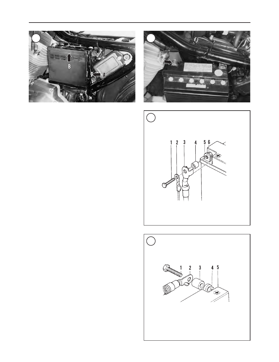
4. Install and tighten the negative battery cable (Figure 2).
5. Coat the battery connections with dielectric grease or
petroleum jelly.
6. Place the top cover (B, Figure 1) on the battery.
7. Attach the forward end of the battery strap (A, Figure 1)
under the front side of the battery tray. Then lay the strap
over and into the groove in the battery top. Insert the
threaded stud on the rear end of the battery strap into the
hole at the rear side of the battery tray. Install the washer
and nut. Tighten the nut securely.

WARNING

After installing the battery, make sure the vent
tube is not pinched. A pinched or kinked tube
will allow high pressure to accumulate in the
battery and cause the battery to explode. If
the vent tube is damaged, replace it.

8. Reconnect the battery vent tube to the battery. If neces-
sary, refer to the

Vent Tube Routing

in this section.

9. Install the seat (Chapter Seventeen).

Vent Tube Routing

The battery vent tube must be routed properly and not

touch any moving parts. Proper routing ensures the vent
hose outlet (A, Figure 10) is positioned away from all
metal components. Replace the vent tube if it is kinked or
plugged.

Connect the vent tube onto the battery vent nipple. The

vent nipple is on the forward side of the battery (B, Figure
8
). Following the transmission housing curve, route the
tube past the transmission and insert the hose through the
vent hose clip on the frame (B, Figure 10). On California
models, continue by inserting the vent tube through the ad-
ditional vent tube clip mounted on the rear muffler mount.
On California models, the vent tube must extend 3 in. (76
mm) down from the bottom of the second clip. On all other
models, the vent tube must extend 3.5 in. (89 mm) down
from the bottom of the clip.

Testing

NOTE

Do not attempt to test a battery with a hy-
drometer immediately after adding water to
the cells. Charge the battery for 15-20 min-
utes at a high rate to cause vigorous gassing.

Use a hydrometer with numbered graduations from 1.100

to 1.300 rather than one with color-coded bands to test the
battery. To use the hydrometer (Figure 11), squeeze the
rubber ball, insert the tip into the cell and release the ball.

Draw enough electrolyte to float the weighted float in-

side the hydrometer. When using a temperature-compen-
sated hydrometer, release the electrolyte and repeat this
process several times to make sure the thermometer has ad-

396

CHAPTER TWELVE

10

11

Take reading at eye level

Do not suck
in too much
electrolyte

Hold tube
vertical

Float must be free

12

justed to the electrolyte temperature before taking the
reading.

NOTE

If a temperature-compensated hydrometer is
not used, add 0.004 to the specific gravity
reading for every 10

°

above 80

°

F (27

°

C).

For every 10

°

below 80

°

F (27

°

C), subtract

0.004.

Hold the hydrometer vertically and note the number in

line with the surface of the electrolyte (Figure 11). This is
the specific gravity for this cell. Return the electrolyte to the
cell from which it came. The specific gravity of the electro-
lyte in each battery cell is an excellent indication of the con-
dition of the cell. Refer to Figure 11. Charging is necessary
if the specific gravity is lower or varies more than 0.050
from cell to cell. After charging, if the specific gravity still
varies more than 0.050, replace the battery.

Test the charging system as described in Chapter Two.

Charging

A good battery should self-discharge approximately one

percent of its given capacity (Figure 12) each day. If a bat-
tery not in use and without any loads connected loses its
charge within a week of being fully charged, the battery is
defective.

If the motorcycle is not used for long periods of time, an

automatic charger with variable voltage and amperage out-
puts is recommended for optimum battery service life.

WARNING

During charging, highly explosive hydrogen
gas is released from the battery. Only charge
the battery in a well-ventilated area away from
open flames, including pilot lights on some gas
home appliances. Do not allow smoking in the
area. Never check the charge of the battery by

arcing across the terminals; the resulting
spark can ignite the hydrogen gas.

CAUTION

Always remove the battery from the motorcy-
cle before connecting the charging equipment.

1. Remove the battery from the motorcycle as described in
this section.

2. Set the battery on a stack of newspapers or shop cloths to
protect the surface of the workbench.

3. Make sure the battery charger is turned off prior to at-
taching the charger leads to the battery.

4. Connect the positive charger lead to the positive battery
terminal and the negative charger lead to the negative bat-
tery terminal.

5. Remove all fill/vent caps (A, Figure 8) from the battery.
Set the charger at 12 volts and switch it on. Normally, a bat-
tery should be charged at a slow charge rate of 1/10 of the
given capacity.

a. As the battery charges, the electrolyte will begin to

bubble (gassing). If one cell does not bubble, it is
usually an indication that it is defective. Refer to the

Load Testing

in this section.

b. The charging time depends on the discharged condition

of the battery. Normally, a battery should be charged at a
slow charge rate of 1/10 of the given capacity.

CAUTION

Maintain the electrolyte level at the upper
level during the charging cycle; check and re-
fill with distilled water as necessary.

6. After the battery has been charged for the predetermined
time, turn off the charger, disconnect the leads, and check the
specific gravity. It should be within the limits in Figure 13. If
it is and remains stable for one hour, the battery is charged.

ELECTRICAL SYSTEM

397

12

10

20

30

40

50

60

70

80

90

100

1.100

1.120

1.140

1.160

1.180

1.200

1.220

1.260

1.280

BATTERY-State of charge (%)

Specific

gra

vity

68

F

(20

C)

°°

1.240

13

Initialization

A new battery must be fully charged to a specific gravity

of 1.260-1.280 before installation. To bring the battery to a
full charge, give it an initial charge. Using a new battery
without an initial charge will cause permanent battery dam-
age. That is, the battery will never be able to hold more than
an 80% charge. Charging a new battery after it has been
used will not bring its charge to 100%. When purchasing a
new battery, verify its charge status.

NOTE

Recycle the old battery. When a new battery is
purchased, turn in the old one for recycling.
Most dealerships will accept the old battery
in trade when purchasing a new one. Never
place an old battery in the household trash
because it is illegal, in most states, to place
any acid or lead (heavy metal) contents in
landfills.

Load Testing

A load test checks the battery performance under full cur-

rent load and is the best indication of battery condition.

A battery load tester is required for this procedure. When

using a load tester, follow the manufacturer’s instructions.
1. Remove the battery from the motorcycle as described in
this section.

NOTE

Let the battery stand for at least one hour af-
ter charging prior to performing this test.

2. The battery must be fully charged before beginning this
test. If necessary, charge the battery as described in this sec-
tion.

WARNING

The battery load tester must be turned off
prior to connecting or disconnecting the test
cables to the battery. Otherwise, a spark
could cause the battery to explode.

CAUTION

To prevent battery damage during load test-
ing, do not load-test a discharged battery and
do not load-test the battery for more than 20
seconds. Performing a load test on a dis-
charged battery can result in permanent bat-
tery damage.

3. Load test the battery as follows:

a. Connect the load tester cables to the battery follow-

ing the manufacturer’s instructions.

b. Load the battery at 50 percent of the cold-cranking

amperage (CCA).

c. After 15 seconds, the voltage reading with the load

still applied must be 9.6 volts or higher at 70

°

F (21

°

C). Now quickly remove the load and turn off the
tester.

4. If the voltage reading is 9.6 volts or higher, the battery
output capacity is good. If the reading is below 9.6 volts,
the battery is defective.

5. With the tester off, disconnect the cables from the bat-
tery.

6. Install the battery as described in this section.

BATTERY

(1997-2003 MODELS)

WARNING

Always wear safety glasses when working
with batteries. If electrolyte is splashed into
the eyes, call a physician immediately, force

398

CHAPTER TWELVE

14

15

Table 10 TUBELESS TIRE SPECIFICATIONS (1991-2003 MODELS)

Front tire

Type

Dunlop D401 Elite S/T

Size

100/90-19

Wheel diameter

19 in.

Rim width and contour

T19 

×

 2.15 MT

Valve stem hole diameter

0.45 in. (11.4 mm)

Type

Dunlop K591 S&FR Elite SP

Size

100/90-V19

Wheel diameter

19 in.

Rim width and contour

T19 

×

 2.15 MT

Valve stem hole diameter

0.45 in. (11.4 mm)

Rear tire

Type

Dunlop D401 Elite S/T

Size

130/90-16

Wheel diameter

16 in.

Rim width and contour

T16 

×

 3.0 D

Valve stem hole diameter

0.35 in. (8.9 mm)

Type

Dunlop K591 S&FR Elite SP

Size

130/90-V16

Wheel diameter

16 in.

Rim width and contour

T16 

×

 3.00 D

Valve stem hole diameter

0.35 in. (8.9 mm)

Table 11 TUBE-TYPE TIRE SPECIFICATIONS (1986-1990 MODELS)

Front tire

Type

Dunlop K181 or K291

Size

MJ90-19

Wheel diameter

19 in.

Rim width and contour

T19 

×

 2.50 MTA

Tube size

MJ90-19

Rear tire

Type

Dunlop K181 or K291

Size

MT90-16

Wheel diameter

16 in.

Rim width and contour

T16 

×

 3.00 D

Tube size

MT90-16

Table 12 TUBE-TYPE TIRE SPECIFICATIONS (1991-2003 MODELS)

Front tire

Type

Dunlop D401 Elite S/T

Size

100/90-19

Wheel diameter

19 in.

Rim width and contour

T19 

×

 2.5 TLA

Tube size

MJ90-19

Type

Dunlop Touring Elite II (1995-1999 models)

Size

MH90-21 56H

Wheel diameter

21 in.

Rim width and contour

T21 

×

 215 TLA

Tube size

3.00-21

Type

Dunlop D401 Elite S/T (2000-2003 models)

Size

MH90-21 56H

Wheel diameter

21 in.

Rim width and contour

T21 

×

 215 TLA

Tube size

3.00-21

Rear tire

Type

Dunlop D401 Elite S/T

Size

130/90-16

Wheel diameter

16 in.

Rim width and contour

T16 

×

 3.00 D

Tube size

MT90-16

Type

Dunlop Touring Elite II (1995-1999 models)

Size

MT90-B16

Wheel diameter

16 in.

Rim width and contour

T16 

×

 3.00 D

Tube size

MT90-16

498

CHAPTER THIRTEEN

Table 13 WHEEL AND SUSPENSION TORQUE SPECIFICATIONS

ft.-lb.

in.-lb.

N•m

Drive sprocket cover screws

90-110

10-12

Drive sprocket lockscrew

1, 2

Chain drive

50-60

6-7

Belt drive

84-108

9-12

Drive sprocket nut

1, 2

1986-1990 models

35-64

47-87

1991-2003 models

3

110-120

149-163

Driven sprocket mounting bolts

4

Cast wheels

1991 models

65-70

88-95

1992 models

45-55

61-75

1993-2003 models

55-65

75-88

Laced wheels

50-55

37-75

Front axle nut

1986-1987 models

50

68

1988-2003 models

50-55

68-75

Front axle pinch bolt

(1988-2003 models)

21-27

28-37

Front brake caliper bolts

25-30

34-41

Fork lower cap nuts

(1986-1987 models)

132

15

Hub plate Torx screws

16-24

22-33

Rear axle nut

60-65

81-88

Rear master cylinder screws

155-190

18-21

1.  See text.
2.  Apply threadlock (Loctite 262 or equivalent).
3.  Left-hand threads
4.  Apply threadlock (Loctite 242 or equivalent).

WHEEL, TIRES AND SECONDARY DRIVE

499

13

CHAPTER FOURTEEN

FRONT SUSPENSION AND STEERING

This chapter covers the handlebar, front fork and steering

components. Refer to Chapter Thirteen for front wheel and
tire service. Tables 1-3 are at the end of this chapter.

WARNING

Replace all fasteners used on the front suspen-
sion and steering components with parts of the
same type. Do not use a replacement part of
lesser quality or substitute design; this may af-
fect the performance of the system or result in
failure of the part that leads to loss of motorcy-
cle control. Careful attention to the torque
specifications during installation is required to
ensure proper retention of these parts.

HANDLEBAR

Inspect the handlebar at regular intervals for loose

mounting bolts or damage. Frequently check the fasteners
securing the master cylinder and turn signals to the handle-
bar. Make sure no fastener is loose or missing.

Replace the handlebar if it is bent or damaged. Never try

to heat, bend or weld handlebars.

Removal

Refer to Figure 1 and Figure 2.

1. Position the motorcycle on a suitable stand.

2. Remove the mirrors.

CAUTION

Cover the front fender and front wheel with a
heavy cloth or plastic tarp to protect them
from accidental brake fluid spills. Brake fluid
can damage painted and plastic surfaces. Im-
mediately wash the surfaces that come into
contact with brake fluid with soapy water and
rinse completely.

3. Remove the bolts securing the master cylinder (A, Fig-
ure 3
). Support the master cylinder so it does not hang from
the brake line. Make sure brake fluid does not spill from the
master cylinder.

NOTE

Make a drawing of the clutch and throttle ca-
ble routing before removal.

FRONT SUSPENSION AND STEERING

501

14

1

HANDLEBAR ASSEMBLY

(ALL MODELS EXCEPT 883C AND 1200C MODELS)

1. Allen bolt (short)
2. Allen bolt (long)
3. Washer (1991-2003 models)
4. Spacer (1986-1994 models)
5. Upper handlebar clamp
6. Lockwasher (1986-1990 models)
7. Handlebar
8. Lower right handlebar clamp
9. Locknut

10. Lower left handlebar clamp
11. Cup washer
12. Rubber bushing
13. Stud
14. Spacer
15. Ground wire
16. Locknut
17. Bolt

2

HANDLEBAR (883C AND 1200C MODELS)

1. Bolt
2. Washer
3. Handlebar
4. Lower clamp
5. Riser cover
6. Rubber bushing
7. Upper triple clamp
8. Spacer
9. Cup washer

10. Ground wire
11. Upper clamp

4. Loosen the throttle housing (B, Figure 3) screws so
that the housing can slide off of the handlebar later in this
procedure. It is not necessary to separate the housing
halves.
5. Remove the left switch housing (A, Figure 4) screws
and separate the housing halves (Figure 5).
6. Remove the clutch lever clamp mounting screws (B,
Figure 4) and separate the clamp halves.
7. Disconnect or remove any clamps securing electrical ca-
bles to the handlebar.
8. On 883C and 1200C models, remove the riser covers.
9. If lower handlebar holder removal is required, loosen
the holder bolts or nuts, but do not remove the bolts or
nuts.
10. Loosen the handlebar clamp bolts (Figure 6). Remove
the handlebar clamp bolts, then remove the instrument clus-
ter and clamp. Do not lose the washers or spacers, if so
equipped.
11. Remove the handlebar.

Inspection

1. Clean the knurled section of the handlebar with a wire
brush and remove any debris in the knurling.
2. Check the handlebar for cracks, bends or other damage.
Replace the handlebar if necessary. Do not attempt to repair
it.
3. Clean the clamps and holders thoroughly before install-
ing the handlebar.

Installation

1. Install the handlebar in the lower holder(s).
2A. On all models except 883C and 1200C, install the
clamp and instrument housing using the following proce-
dure:

a. Install the handlebar clamp and two rear clamp

bolts.

b. Install the instrument housing and two front clamp

bolts.

c. Tighten the rear clamp bolts first, then tighten the

front clamp bolts. Tighten the clamp bolts to 144-180
in.-lb. (16-20 N•m).

2B. On 883C and 1200C models, install the clamp and in-
strument housing as follows:

a. Install the handlebar clamp and two front clamp

bolts.

b. Install the instrument housing and two rear clamp

bolts.

c. Tighten the front clamp bolts first, then tighten the

rear clamp bolts. Tighten the clamp bolts to 144-180
in.-lb. (16-20 N•m).

d. Install the riser covers.

3. After installing the handlebar, sit on the motorcycle and
check the handlebar position. Adjust the handlebar as
needed.

502

CHAPTER FOURTEEN

3

4

5

6

4. Install the right switch housing (Chapter Twelve).

5. Install the left switch housing (Chapter Twelve).

6. Install the clutch lever (Chapter Three).

7. Refer to Chapter Sixteen and install the front master cyl-
inder onto the handlebar.

8. Reinstall the wiring and cable retaining clamps.

9. Install the mirrors.

FRONT FORK

(ALL MODELS EXCEPT 1200S)

The front suspension consists of a spring-controlled, hy-

draulically dampened telescopic fork.

Before suspecting major trouble, drain the front fork oil

and refill with the proper type and quantity (Chapter
Three). If the trouble persists, such as poor damping, a ten-
dency to bottom or top out or leaks around the rubber seals,
follow the service procedures in this section.

To simplify fork service and to prevent the mixing of

parts, remove, service and install the legs individually.

Removal

1. Support the motorcycle so the front wheel clears the
ground. Make sure the motorcycle is stable before remov-
ing the front wheel and fork.
2. Remove the front wheel as described in Chapter Thir-
teen.
3. Remove the front fender as described in Chapter Seven-
teen.
4. On models equipped with a lower fork stem cover,
loosen the cover screws and raise the cover for access to the
lower fork pinch bolts.

NOTE

Label the left and right fork tubes so they can
be reinstalled in their original positions,

5. Loosen the upper fork bracket pinch bolt (A, Figure 7).
6. If fork tube disassembly is required, loosen but do not
remove the fork cap (B, Figure 7).
7. On 1986-1987 models, remove the cap bolt (B, Figure 7).
8. Loosen the lower fork bracket pinch bolt (Figure 8) and
slide the fork tube out of the fork brackets. If necessary, ro-
tate the fork tube while removing it.
9. If fork service is required, refer to

Disassembly

in this

section.

Installation

NOTE

The fork assemblies must be reinstalled on the
correct side of the motorcycle so the brake
caliper and front fender can be properly in-
stalled. If the fork assemblies are installed on
the wrong side, the bolt holes on these compo-
nents will not align properly.

1. Clean off any corrosion or dirt on the upper and lower
fork bracket receptacles.
2. On 1988-2003 models, install each fork tube so the tube
extends 0.42-0.50 in. (10.7-12.7 mm) above the upper fork
bracket as shown in Figure 9.
3. Tighten the lower bracket pinch bolt (Figure 8) to 30
ft.-lb. (14 N•m).
4. If loose, tighten the fork cap (B, Figure 7) securely.

FRONT SUSPENSION AND STEERING

503

14

7

8

9

0.42-0.50 in.
(10.7-12.7 mm)

Cap bolt

Bracket

Fork tube

504

CHAPTER FOURTEEN

10

FRONT FORK

(ALL MODELS EXCEPT 1995-2003 1200S)

1988

1. Cap bolt
2. Washer

(1986-1987 models)

3. O-ring
4. Spring
5. Piston rings
6. Damper rod
7. Rebound spring
8. Fork tube
9. Lower bushing

10. Oil lock piece
11. Dust cover
12. Retaining ring
13. Oil seal
14. Seal spacer
15. Upper bushing
16. Slider

17A. Drain screw

(1986-1987 models)

17B. Drain screw

(1988-2003 models)

18A. Washer

(1986-1987 models)

18B. Washer

(1988-2003 models)

19A. Washer

(1986-1987 models)

19B. Washer

(1988-2003 models)

20A. Allen bolt

(1986-1987 models)

20B. Allen bolt

(1988-2003 models)

5. Tighten the upper bracket pinch bolt (A, Figure 7) to the
torque specification in Table 1.

6. Install the front fender as described in Chapter Seven-
teen.

7. Install the front wheel as described in Chapter Thirteen.

8. Apply the front brake and operate the front fork several
times to seat the fork and front wheel.

Disassembly

Refer to Figure 10.

NOTE

Fork holding tools are available (

Figure 11

,

typical), and such a tool may be shown in the
following illustrations. However, the text re-
fers to the use of a vise as a holding tool.

1. Using the front axle boss at the bottom of the fork tube,
clamp the slider in a vise with soft jaws. Do not clamp the
slider at any point above the fork axle boss.

NOTE

Loosen the bottom Allen bolt before remov-
ing the fork cap and spring. Leaving the cap
on provides spring tension against the
damper rod. This prevents the damper rod
from spinning when attempting to loosen the
Allen bolt.

2. Loosen, but do not remove, the Allen bolt (Figure 12) at
the bottom of the slider.

WARNING

Keep body parts away from the fork cap when
removing it. The fork cap is under spring
pressure and may fly off when loosening it. In
addition, make sure the fork tube is fully ex-
tended from the slider. If the fork is damaged
and stuck in a compressed state, the fork
should be disassembled by a dealership.

3. Remove the fork cap (Figure 13) from the top of the
fork tube. Then pull the spring out of the fork tube.

4. Remove the fork tube from the vise and pour the oil into
a drain pan. Pump the fork several times by hand to get
most of the oil out. Check the oil for contamination, indicat-
ing worn or damaged parts. Discard the oil after examining
it.

5A. On 1986-1987 models, insert a small flat-tipped
screwdriver under the dust cover (11, Figure 10) and pry
the cover off of the slider and remove it. Be careful not to
damage the slider surface.

5B. On 1988-2003 models, insert a small punch in the
notch under the dust cover (Figure 14) and drive the cover
off the slider and remove it. Do not damage the slider sur-
face.

FRONT SUSPENSION AND STEERING

505

14

11

12

13

14

6. Insert a small flat-tipped screwdriver under the dust seal
(Figure 15) and pry the seal out of the slider and remove it.
Do not damage the slider surface.
7. Pry the retaining ring (Figure 16) out of the groove in
the slider and remove it. See Figure 17.
8. Remove the Allen screw and washer (Figure 18) at the
bottom of the slider.

NOTE

The slider bushing is installed with an inter-
ference fit. When separating the fork tube and
slider, the slider bushing, spacer seal and oil
seal will be removed at the same time.

9. Hold the fork tube in one hand then pull the slider away
repeatedly, knocking the slider bushing against the fork
tube bushing (Figure 19). As the slider bushing is knocked
out of the slider, it will push the oil seal and seal spacer out
of the slider. Continue until these components are pushed
out of the slider.
10. Remove the oil lock piece (Figure 20) from the
damper rod.
11. Remove the damper rod and small spring (Figure 21)
from the fork tube.

Inspection

NOTE

Handle the guide bushings (

Figure 22

) care-

fully when cleaning them to avoid scratching
or removing any of their coating material. If
there is any metal powder clinging to the
guide bushings, clean them with new fork oil
and a nylon brush.

1. Initially clean all of the fork components in solvent, first
making sure the solvent will not damage the rubber parts.
Then clean with soap and water and rinse with clear water.
Dry thoroughly.
2. Check the fork tube (A, Figure 23) for bends, nicks, rust
or other damage. Check the fork tube for straightness with a
set of V-blocks and a dial indicator. If these tools are not
available, roll the fork tube on flat surface like a place of
glass. The manufacturer does not provide service limit

506

CHAPTER FOURTEEN

15

16

17

18

19

specifications for runout. If a fork tube is slightly bent,
check with a dealership to see if it can be straightened. If a
fork tube is creased or wrinkled, replace the fork tube.
3. Check the slider (B, Figure 23) for dents or other exte-
rior damage. Check the retaining ring groove (Figure 24) in
the top of the slider for cracks or other damage. Replace the
slider if the groove is cracked or damaged.
4. Check the slider and fork tube bushings (Figure 25) for
severe wear, cracks or damage. The slider bushing was re-
moved with the oil seal. The fork tube bushing should not
be removed unless replacement is required. To replace the
fork tube bushing, perform the following:

a. Expand the bushing slit using a screwdriver and slide

it off the fork tube.

b. Coat the new bushing with new fork oil.
c. Install the new bushing by expanding the slit using a

screwdriver. Expand the bushing only enough to fit it
over the fork tube.

d. Seat the new bushing (Figure 25) into the groove in

the fork tube.

5. Replace the drain screw, Allen bolt or washers if
damaged.
6. Check the damper rod piston rings (Figure 26) for se-
vere wear, cracks or other damage. If necessary, replace
both rings as a set.
7. Check the damper rod for straightness using a set of
V-blocks and a dial indicator (Figure 27) or by rolling it on

FRONT SUSPENSION AND STEERING

507

14

20

21

22

23

24

25

a flat surface, like a plate glass. The manufacturer does not
provide service limit specifications for runout.
8. Make sure the oil passage holes in the damper rod (Fig-
ure 28
) are open. If clogged, flush with solvent and dry
with compressed air.
9. Check the threads in the bottom of the damper rod for
stripping, cross-threading or sealer residue. If necessary,
use a tap to renew the threads or to remove any deposits.
10. Check the damper rod rebound spring and the fork
spring for wear or damage. The manufacturer does not pro-
vide service limit specifications for spring free length.
11. The manufacturer specifies that the oil seals (A, Figure
29
) should be replaced whenever they are removed. If in-
stalling the original oil seals, inspect them closely for wear,
hardness or other damage. Always replace both oil seals as
a set.
12. Inspect the outer dust seal(s) (B, Figure 29) for cracks,
weather deterioration or other damage. Replace if
damaged.
13. Replace the fork cap O-ring if leaking or damaged.
14. Any parts that are worn or damaged should be re-
placed. When replacing fork springs, replace both springs
as a set; do not replace only one spring. Simply cleaning
and reinstalling unserviceable components will not im-
prove performance of the front suspension.

Assembly

Refer to Figure 10.

1. Prior to assembly, perform the inspection procedure in
this section. Clean all parts before assembly.
2. Coat all parts with the specified fork oil (Chapter Three)
before assembly.
3. Install the rebound spring onto the damper rod (Figure
30
) and slide the rod into the fork tube until it protrudes
from the end of the tube.
4. Install the oil lock piece (Figure 31) onto the end of the
damper rod.
5. Insert the fork spring (Figure 32) into the fork tube so
that the tapered end of the spring faces toward damper rod.
Install the fork cap to tension the spring and hold the
damper rod in place.

508

CHAPTER FOURTEEN

26

27

28

29

30


Content      ..     35      36      37      38     ..