Great Wall. Service manual for chassis and body (2006) - page 29
BE-55
Body Electric System
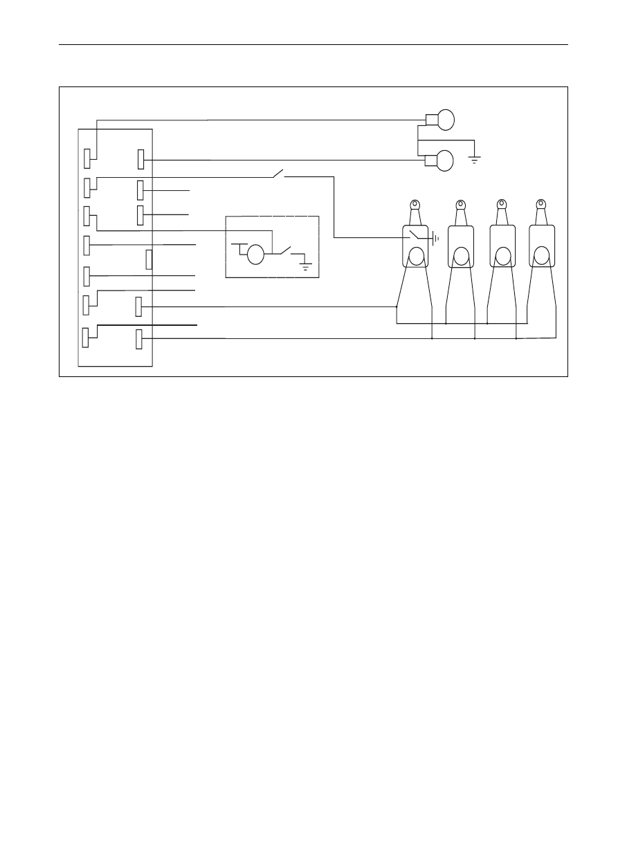
CCL and Electric Rocker Gear System
Definition of the connecting wire of CCL
1. G/R (G/W) Turn lamp
Connected to the anode wire of the turn lamp (right ) on vehicle, it will output 12 V voltage
when it is in operation
2. O
w/b1)
Window-shutting signal output
This wire has one second of voltage output of 12V when the car door is locking. (top SY SJ)
3. No connection
4. G (Y) Unlocking output of CCL
Connected to the locking wire of actuator of CCL, and the normally closed contact in the
internal relay is the grounding wire.It will output 12 v voltage when locking with REMOTE
CONTROLLER or manually because the common spot of relay will contact the normally
opening contact.
5. Bl (G) Locking output of CCL
Connected to the locking wire of actuator of CCL, and the normally closed contact inside
the internal relay is the grounding wire.It will output 12 V voltage when locking with
REMOTE CONTROLLER or manually because the common sots of relay will contact
with the normally opening contact.
6. Gr (G/B) Turn lamp
Connected to the anode wire of left turn lamp of vehicle, it will output 12 v Voltage when in
operation.
7. W (W) Manually controlled unlocking signal
The door lock control the locking process through the manual unlocking switch at left front
door, that is, under the locking condition, press the switch, the lock will be opened (the
switch will return to the connection situation automatically after pressing.
8. Br (R/B) Negative output of door switch
Connected to the car door lamp switch, it is connected to the grounding wire (the indoor
lamp will light when opening the door.
9. R/G (G/B) Rotating speed test
The car door will lock automatically when the vehicle reaches a certain speed.
10. W(R )
ACC test
Connect to the ACC wire, which will have 12 V voltage when the key is rotated to the ACC position.
11. R (R )
Power anode (12V)
Connect to the anode of accumulator on vehicle, in front of which should be set the fuse
so that the voltage will be no less than 10V when the starter is in operation.
12. B(B) Power cathode
Connect to the body (grounding wire), it should be short as possible as can because the
overlong wire will produce the interference source.
SY SJ
1
2
3
4
5
6
7
8
9
10
11
12
left turning light
manual switch locking signal
closing window output
none
door switch negative input
speed test
ACC test
power anode 12V
remote control opening lock output
power cathode
remote control closing lock output
12V
W
K
door switch
K
M
M
M
M
Items in the parenthesis is for SY diesel model
Items with
are configuration for SJ and top SY