Ford Mondeo (petrol engines). Manual - part 96
 

  Index      Ford     Ford Mondeo - service and repair manual (petrol engines)


Search            


Content   ..  94  95  96  97   ..


Ford Mondeo (petrol engines). Manual - part 96


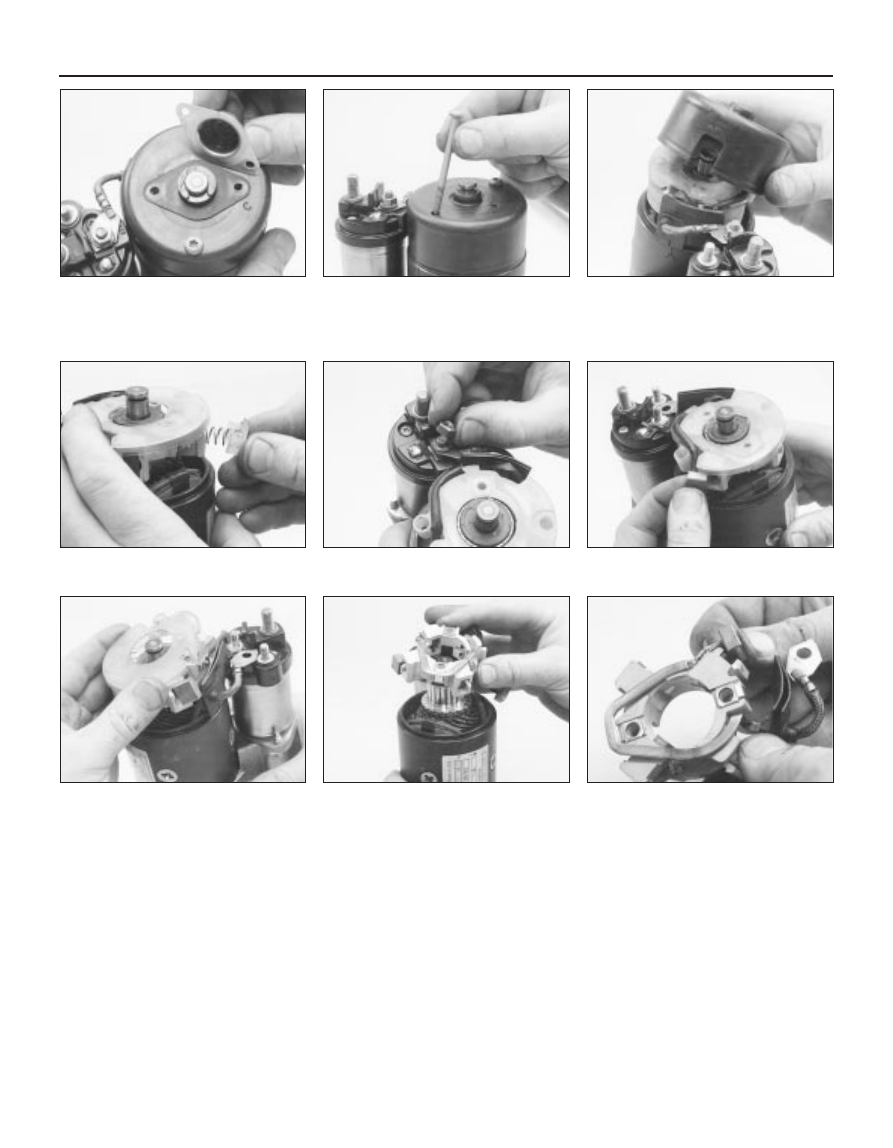
Brush renewal

Remove the brushes as shown (see
illustrations)
.
In some cases, the brushes will have wear
limit marks, in the form of a groove etched
along one face of each brush; when the
brushes are worn down to these marks, they
must be renewed. If no marks are provided,
measure the length of each brush, and
compare it with the minimum length given in
the Specifications Section of this Chapter. If
any brush is worn below this limit, renew the
brushes as a set. If the brushes are still
serviceable, clean them with a petrol-

moistened cloth. Check that the spring
pressure is equal for all brushes, and holds
the brushes securely against the commutator.
If in doubt about the condition of the brushes
and springs, compare them with new
components.
Clean the commutator with a petrol-
moistened cloth, then check for signs of
scoring, burning, excessive wear or severe
pitting. If worn or damaged, the commutator
should be attended to by an auto-electrician.
Refitting is the reverse of the removal
procedure.

Solenoid renewal

Unscrew the nut, noting the lockwasher(s),
and disconnect the motor link from the
solenoid terminal.
Unscrew the two bolts securing the
solenoid to the motor drive end housing.
Release the solenoid plunger from the
starter engaging lever, then withdraw the
solenoid, noting the spring.
Refitting is the reverse of the removal
procedure. Clean the solenoid, its plunger and
the motor/solenoid mating surfaces carefully,
and lubricate the plunger/starter engaging
lever surfaces with a smear of grease.

17.2G  . . . lift off the plastic insulating 

plate . . .

17.2H  . . . remove the brushbox and

remove the positive brushes complete with

the bus bar . . .

17.2I  . . . note how the bus bar is engaged

on the brushbox before removing it

5•8 Engine electrical systems

17.2A  Remove the two screws to release

the end cap. Withdraw the gasket and

prise out the C-clip, noting any shims fitted

to control armature endfloat . . .

17.2B  . . . unscrew the two screws . . .

17.2C  . . . and withdraw the end 

housing . . .

17.2D  . . . then unclip the brush holders

and springs . . .

17.2E  . . . unscrew the nut securing the

solenoid link . . .

17.2F  . . . withdraw the negative 

brushes . . .

Chapter 6 Emissions control systems

Catalytic converter - general information, checking 

and component renewal  . . . . . . . . . . . . . . . . . . . . . . . . . . . . . . . .

9

Diagnosis system - general information  . . . . . . . . . . . . . . . . . . . . . .

3

Electronic control system - description and precautions  . . . . . . . . .

2

Engine compartment wiring check  . . . . . . . . . . . . . . .

See Chapter 1

EVAPorative emissions control (EVAP) system - general 

information, checking and component renewal  . . . . . . . . . . . . . .

5

Exhaust Gas Recirculation (EGR) system - general 

information, checking and component renewal  . . . . . . . . . . . . . .

6

Exhaust system check  . . . . . . . . . . . . . . . . . . . . . . . . .

See Chapter 1

General information . . . . . . . . . . . . . . . . . . . . . . . . . . . . . . . . . . . . . .

1

Information sensors - general information, testing, 

removal and refitting  . . . . . . . . . . . . . . . . . . . . . . . . . . . . . . . . . . .

4

Positive Crankcase Ventilation (PCV) system - general 

information, checking and component renewal  . . . . . . . . . . . . . .

8

Positive Crankcase Ventilation (PCV) system check 
and filter cleaning . . . . . . . . . . . . . . . . . . . . . . . . . . . . .

See Chapter 1

Pulse-air system - general information, checking 

and component renewal  . . . . . . . . . . . . . . . . . . . . . . . . . . . . . . . .

7

Underbonnet hose check . . . . . . . . . . . . . . . . . . . . . . .

See Chapter 1

Crankshaft speed/position sensor

Resistance . . . . . . . . . . . . . . . . . . . . . . . . . . . . . . . . . . . . . . . . . . . . . . . .

200 to 450 ohms

Camshaft position sensor

Resistance . . . . . . . . . . . . . . . . . . . . . . . . . . . . . . . . . . . . . . . . . . . . . . . .

200 to 900 ohms

Intake air temperature sensor

Resistance:

At -40°C . . . . . . . . . . . . . . . . . . . . . . . . . . . . . . . . . . . . . . . . . . . . . . . .

860 to 900 k ohms

At 20°C  . . . . . . . . . . . . . . . . . . . . . . . . . . . . . . . . . . . . . . . . . . . . . . . .

35 to 40 k ohms

At 100°C  . . . . . . . . . . . . . . . . . . . . . . . . . . . . . . . . . . . . . . . . . . . . . . .

1.9 to 2.5 k ohms

At 120°C  . . . . . . . . . . . . . . . . . . . . . . . . . . . . . . . . . . . . . . . . . . . . . . .

1.0 to 1.3 k ohms

Throttle potentiometer

Resistance - see text  . . . . . . . . . . . . . . . . . . . . . . . . . . . . . . . . . . . . . . .

400 to 6000 ohms

Power steering pressure switch

Operating pressure - green switch  body:

Contacts open - infinite  resistance  . . . . . . . . . . . . . . . . . . . . . . . . . .

31.5 ± 3.5 bars

Contacts close - 0 to 2.5 ohms  resistance  . . . . . . . . . . . . . . . . . . . .

Between 13.5 and 24.0 bars

Charcoal canister-purge solenoid valve

Resistance . . . . . . . . . . . . . . . . . . . . . . . . . . . . . . . . . . . . . . . . . . . . . . . .

50 to 120 ohms

Pulse-air solenoid valve

Resistance . . . . . . . . . . . . . . . . . . . . . . . . . . . . . . . . . . . . . . . . . . . . . . . .

50 to 120 ohms

Torque wrench settings

Nm

lbf ft

Camshaft position sensor screw . . . . . . . . . . . . . . . . . . . . . . . . . . . . . . .

18 to 23

13 to 17

Intake air temperature sensor  . . . . . . . . . . . . . . . . . . . . . . . . . . . . . . . . .

23

17

Oxygen sensor  . . . . . . . . . . . . . . . . . . . . . . . . . . . . . . . . . . . . . . . . . . . .

60

44

Exhaust Gas Recirculation (EGR)  system components:

Valve-to-inlet manifold bolts  . . . . . . . . . . . . . . . . . . . . . . . . . . . . . . . .

9

6

Pipe-to-ignition coil screws . . . . . . . . . . . . . . . . . . . . . . . . . . . . . . . . .

10

7

Pulse-air system components:

Filter housing mounting bolt  . . . . . . . . . . . . . . . . . . . . . . . . . . . . . . . .

47

35

Piping-to-exhaust manifold  sleeve nuts . . . . . . . . . . . . . . . . . . . . . . .

32

24

6•1

Easy, suitable for
novice with little
experience

Fairly easy, suitable
for beginner with
some experience

Fairly difficult, suitable
for competent DIY
mechanic

Difficult, suitable for
experienced  DIY
mechanic

Very difficult,
suitable for expert DIY
or  professional

Degrees of difficulty

Specifications

Contents

6

To minimise pollution of the atmosphere

from incompletely-burned and evaporating
gases, and to maintain good driveability and
fuel economy, a number of emission control
systems are used on these vehicles. They
include the following:
(a) The engine management system

(comprising both fuel and ignition sub-
systems) itself.

(b) Positive Crankcase Ventilation (PCV)

system.

(c) Evaporative Emissions Control (EVAP)

system.

(d) Exhaust Gas Recirculation (EGR) system.
(e) Catalytic converter.

The Sections of this Chapter include

general descriptions, checking procedures
within the scope of the home mechanic, and
component renewal procedures (when
possible) for each of the systems listed above.

Before assuming an emissions control system

is malfunctioning, check the fuel and ignition
systems carefully (see Chapters 4 and 5). The
diagnosis of some emission control devices
requires specialised tools, equipment and
training. If checking and servicing become too
difficult, or if a procedure is beyond the scope of

your skills, consult your dealer service
department or other specialist.

This doesn’t mean, however, that emission

control systems are particularly difficult to
maintain and repair. You can quickly and
easily perform many checks, and do most of
the regular maintenance, at home with
common tune-up and hand tools. Note: The
most frequent cause of emissions problems is
simply a loose or broken electrical connector
or vacuum hose, so always check the
electrical connectors and vacuum hoses first.

Pay close attention to any special

precautions outlined in this Chapter. It should
be noted that the illustrations of the various
systems may not exactly match the system
installed on your vehicle, due to changes
made by the manufacturer during production
or from year-to-year.

Vehicles sold in some areas will carry a

Vehicle Emissions Control Information (VECI)
label, and a vacuum hose diagram located in
the engine compartment. These contain
important specifications and setting
procedures for the various emissions control
systems, with the vacuum hose diagram
identifying emissions control components.
When servicing the engine or emissions
systems, the VECI label in your particular
vehicle should always be checked for up-to-
date information.

Description

The EEC-IV (Ford’s fourth-generation

Electronic Engine Control system) engine
management system controls fuel injection by
means of a microcomputer known as the ECU
(Electronic Control Unit) (see illustrations).

The ECU receives signals from various

sensors, which monitor changing engine
operating conditions such as intake air mass
(ie, intake air volume and temperature),
coolant temperature, engine speed,
acceleration/deceleration, exhaust oxygen
content, etc. These signals are used by the
ECU to determine the correct injection
duration.

The system is analogous to the central

nervous system in the human body - the
sensors (nerve endings) constantly relay
signals to the ECU (brain), which processes
the data and, if necessary, sends out a
command to change the operating
parameters of the engine (body) by means of
the actuators (muscles).

Here’s a specific example of how one

portion of this system operates. An oxygen
sensor, located in the exhaust downpipe,

2 Electronic control system -

description and precautions

1 General information

6•2 Emissions control systems

Emissions control systems  6•3

6

2.1B  Location of principal fuel injection, ignition and

emissions control system components

2.1A  Engine management system, showing fuel injection, 

ignition and emissions control sub-systems

1  ECU (Electronic Control Unit)
2  Fuel pump/fuel gauge sender

unit

3  Fuel pump relay
4  Fuel filter
5  Idle speed control valve
6  Air mass meter
7  Air cleaner assembly
8  Fuel pressure regulator
9  Fuel rail

10  Throttle potentiometer
11  Intake air temperature sensor
12  Fuel injector
13  Camshaft position sensor
14  Charcoal canister
15  Charcoal canister-purge

solenoid valve

16  Ignition coil
17  Battery
18  Ignition module - only

separate (from ECU) on
vehicles with automatic
transmission

19  Coolant temperature sensor
20  Oxygen sensor
21  Crankshaft speed/position

sensor

22  Power supply relay
23  Power steering pressure

switch

24  Air conditioning compressor

clutch solenoid

25  Service connector - for octane

adjustment

26  Self-test connector - for Ford

STAR tester diagnostic
equipment

27  Diagnosis connector - for Ford

diagnostic equipment FDS
2000

28  Ignition switch
29  Fuel cut-off switch
30  Exhaust Gas Recirculation

(EGR) solenoid valve

31  Exhaust Gas Recirculation

(EGR) valve

32  Exhaust Gas Recirculation

(EGR) exhaust gas pressure
differential sensor

33  Exhaust Gas Recirculation

(EGR) pressure differential
measuring point

34  To inlet manifold
35  Pulse-air filter housing
36  Pulse-air solenoid valve
37  Air conditioning/radiator

electric cooling fan control

38  Automatic transmission

control system - where
applicable

1  ECU (Electronic Control Unit)
2  Self-test, diagnosis and service connectors 

(left to right)

3  Bulkhead component mounting bracket - manual

transmission - showing from left to right, (EGR) solenoid
valve, pulse-air solenoid valve and (EGR) exhaust gas
pressure differential sensor

4  Bulkhead component mounting bracket - automatic

transmission - showing from left to right, (EGR) solenoid
valve, pulse-air solenoid valve and (EGR) exhaust gas
pressure differential sensor, with separate ignition module
above

5  Throttle housing, including potentiometer
6  Idle speed control valve
7  Intake air temperature sensor
8  Air mass meter
9  Exhaust Gas Recirculation (EGR) valve

10  Coolant temperature sensor
11  Crankshaft speed/position sensor
12  Pulse-air filter housing
13  Oxygen sensor
14  Ignition coil and spark plug (HT) leads
15  Camshaft position sensor
16  Fuel injector(s)
17  Power steering pressure switch
18  Air cleaner assembly
19  Air intake tube and resonators - under left-hand front wing
20  Resonator


Content   ..  94  95  96  97   ..