Ford Mondeo (petrol engines). Manual - part 20
 

  Index      Ford     Ford Mondeo - service and repair manual (petrol engines)


Search            


Content   ..  18  19  20  21   ..


Ford Mondeo (petrol engines). Manual - part 20


remove the piston/connecting rod assemblies
may result in piston ring breakage.
Slacken each of the big-end bearing cap
bolts half a turn at a time, until they can be
removed by hand. Remove the No 1 cap and
bearing shell. Don’t drop the shell out of the
cap.
Remove the upper bearing shell, and push
the connecting rod/piston assembly out
through the top of the engine. Use a wooden
hammer handle to push on the connecting
rod’s bearing recess. If resistance is felt,
double-check that all of the ridge was
removed from the cylinder.
Repeat the procedure for the remaining
cylinders.
10 After removal, reassemble the big-end
bearing caps and shells on their respective
connecting rods, and refit the bolts finger-
tight. Leaving the old shells in place until
reassembly will help prevent the bearing
recesses from being accidentally nicked or
gouged. New shells should be used on
reassembly.
11 Don’t attempt to separate the pistons
from the connecting rods - see Section 12.

Note: The crankshaft can be removed only
after the engine/transmission has been
removed from the vehicle. It is assumed that
the transmission and flywheel/driveplate,
timing belt, cylinder head, sump, oil pump
pick-up/strainer pipe and oil baffle, oil pump,
and piston/connecting rod assemblies, have
already been removed. The crankshaft left-
hand oil seal carrier must be unbolted from
the cylinder block/crankcase before
proceeding with crankshaft removal.
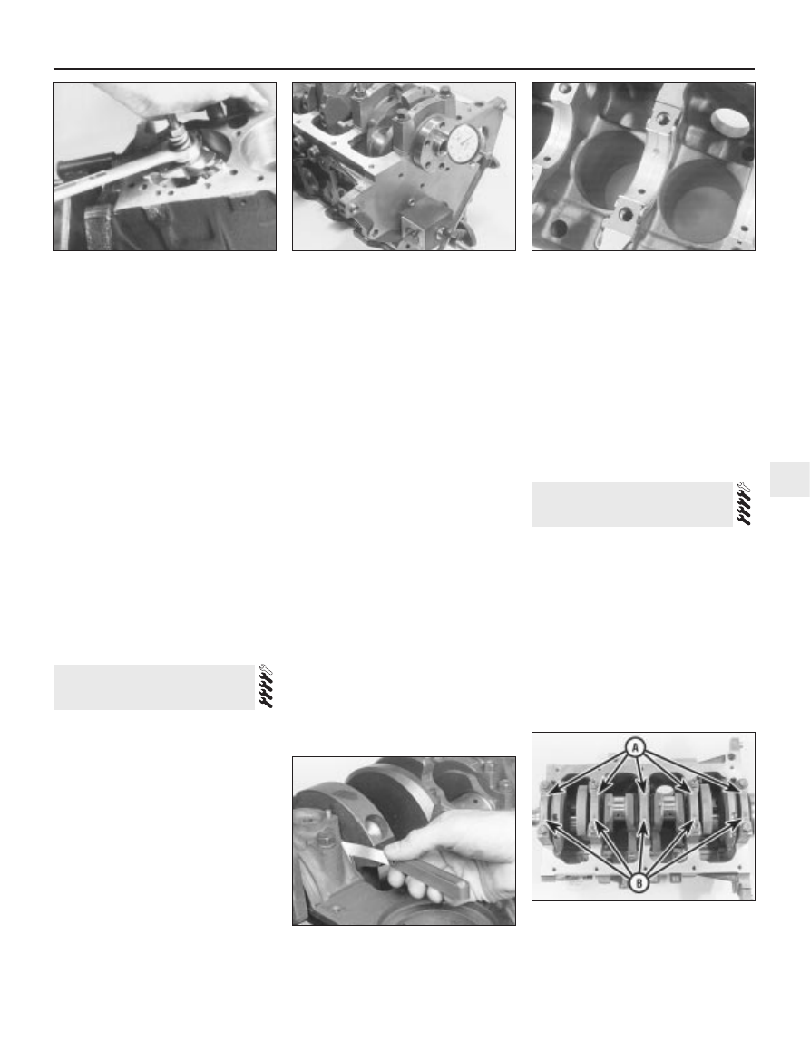
Before the crankshaft is removed, check
the endfloat. Mount a DTI (Dial Test Indicator,
or dial gauge) with the stem in line with the
crankshaft and just touching the crankshaft
(see illustration).
Push the crankshaft fully away from the
gauge, and zero it. Next, lever the crankshaft
towards the gauge as far as possible, and

check the reading obtained. The distance that
the crankshaft moved is its endfloat; if it is
greater than specified, check the crankshaft
thrust surfaces for wear. If no wear is evident,
new thrustwashers should correct the
endfloat; these are part of the No 3 (centre)
main bearing upper shell (see illustration).
If no dial gauge is available, feeler gauges
can be used. Gently lever or push the
crankshaft all the way towards the right-hand
end of the engine. Slip feeler gauges between
the crankshaft and the right-hand face of the
No 3 (centre) main bearing to determine the
clearance (see illustration).
Check the main bearing caps, to see if they
are marked to indicate their locations (see
illustration)
. They should be numbered
consecutively from the timing belt end of the
engine - if not, mark them with number-
stamping dies or a centre-punch. The caps will
also have an embossed arrow pointing to the
timing belt end of the engine. Noting the
different fasteners (for the oil baffle nuts) used on
caps 2 and 4, slacken the cap bolts a quarter-
turn at a time each, starting with the left- and
right-hand end caps and working toward the
centre, until they can be removed by hand.
Gently tap the caps with a soft-faced
hammer, then separate them from the cylinder
block/crankcase. If necessary, use the bolts
as levers to remove the caps. Try not to drop
the bearing shells if they come out with the
caps.

Carefully lift the crankshaft out of the
engine. It may be a good idea to have an
assistant available, since the crankshaft is
quite heavy. With the bearing shells in place in
the cylinder block/crankcase and main
bearing caps, return the caps to their
respective locations on the block, and tighten
the bolts finger-tight. Leaving the old shells in
place until reassembly will help prevent the
bearing recesses from being accidentally
nicked or gouged. New shells should be used
on reassembly.

Note: Always check first what replacement
parts are available before planning any
overhaul operation; refer to Section 1 of this
Part. A Ford dealer, or a good engine
reconditioning specialist/automotive parts
supplier may be able to suggest alternatives
which will enable you to overcome the lack of
replacement parts.

Cleaning

For complete cleaning, remove the water
pump, all external components, and all
electrical switches/sensors. Unbolt the
piston-cooling oil jets or blanking plugs (as

11 Cylinder block/crankcase -

cleaning and inspection

10 Crankshaft - removal

Engine removal and general engine overhaul procedures  2B•13

2B

10.3  Checking crankshaft endfloat with a

feeler gauge

10.4  Before unbolting crankshaft main

bearing caps, note arrows pointing to timing

belt end of engine (A), and bearing numbers

(B) consecutive from timing belt end

9.6  A ridge reamer may be required, to

remove the ridge from the top of each

cylinder - do this before removing the

pistons!

10.1  Checking crankshaft endfloat with a

dial gauge

10.2  Thrustwashers integral with No 3

(centre) main bearing upper shell control

crankshaft endfloat

applicable); note that Ford state that the
piston-cooling oil jets (where fitted) must be
renewed whenever the engine is dismantled
for full overhaul (see illustrations).
Remove the main bearing caps, and
separate the bearing shells from the caps and
the cylinder block/crankcase. Mark or label
the shells, indicating which bearing they were
removed from, and whether they were in the
cap or the block, then set them aside (see
illustration)
. Wipe clean the block and cap
bearing recesses, and inspect them for nicks,
gouges and scratches.
Scrape all traces of gasket from the cylinder

block/crankcase, taking care not to damage
the sealing surfaces.
Remove all oil gallery plugs (where fitted).
The plugs are usually very tight - they may
have to be drilled out and the holes re-tapped.
Use new plugs when the engine is
reassembled. Drill a small hole in the centre of
each core plug, and pull them out with a car
bodywork dent puller (see illustration).

Caution: The core plugs (also
known as freeze or soft plugs)
may be difficult or impossible to
retrieve if they are driven into the
block coolant passages.

If any of the castings are extremely dirty, all
should be steam-cleaned.
After the castings are returned from steam-
cleaning, clean all oil holes and oil galleries
one more time. Flush all internal passages
with warm water until the water runs clear,
then dry thoroughly, and apply a light film of
oil to all machined surfaces, to prevent
rusting. If you have access to compressed air,
use it to speed the drying process, and to
blow out all the oil holes and galleries. 

Warning: Wear eye protection
when using compressed air!

If the castings are not very dirty, you can do
an adequate cleaning job with hot soapy
water (as hot as you can stand!) and a stiff
brush. Take plenty of time, and do a thorough
job. Regardless of the cleaning method used,
be sure to clean all oil holes and galleries very
thoroughly, and to dry all components
completely; protect the machined surfaces as
described above, to prevent rusting.
All threaded holes must be clean and dry,
to ensure accurate torque readings during
reassembly; now is also a good time to clean
and check the threads of all principal bolts -
however, note that some, such as the cylinder
head and flywheel/driveplate bolts, are to be
renewed as a matter of course whenever they
are disturbed. Run the proper-size tap into

2B•14 Engine removal and general engine overhaul procedures

11.1A  Remove water pump . . .

11.1B  . . . crankcase breather pipe and

PCV valve . . .

11.1C  . . . unbolt crankcase ventilation

system oil separator . . .

11.1F  . . . but note that piston-cooling oil

jets (where fitted) must be renewed as a

matter of course whenever engine is

overhauled

11.2  Felt marker pens can be used as

shown to identify bearing shells without

damaging them

11.1D  . . . remove electrical

switches/sensors such as crankshaft

speed/position sensor . . .

11.1E  . . . unbolt blanking plugs (where

fitted) to clean out oilways . . .

11.4  The core plugs should be removed

with a puller - if they’re driven into the

block, they may be impossible to 

retrieve

each of the holes, to remove rust, corrosion,
thread sealant or sludge, and to restore
damaged threads (see illustration). If
possible, use compressed air to clear the
holes of debris produced by this operation; a
good alternative is to inject aerosol-applied
water-dispersant lubricant into each hole,
using the long spout usually supplied. 

Warning: Wear eye protection
when cleaning out these holes in
this way, and be sure to dry out
any excess liquid left in the holes.

When all inspection and repair procedures
are complete (see below) and the block is
ready for reassembly, apply suitable sealant
to the new oil gallery plugs, and insert them
into the holes in the block. Tighten them
securely. After coating the sealing surfaces of
the new core plugs with suitable sealant,
install them in the cylinder block/crankcase
(see illustration). Make sure they are driven
in straight and seated properly, or leakage
could result. Special tools are available for
this purpose, but a large socket with an
outside diameter that will just slip into the
core plug, used with an extension and
hammer, will work just as well.
10 Refit the blanking plugs or (new) piston-
cooling oil jets (as applicable), tightening their
Torx screws to the torque wrench setting
specified (see illustration). Refit also all other
external components removed, referring to

the relevant Chapter of this manual for further
details where required. Refit the main bearing
caps, and tighten the bolts finger-tight.
11 If the engine is not going to be
reassembled right away, cover it with a large
plastic bag to keep it clean; protect the
machined surfaces as described above, to
prevent rusting.

Inspection

12 Visually check the castings for cracks and
corrosion. Look for stripped threads in the
threaded holes. If there has been any history
of internal coolant leakage, it may be
worthwhile having an engine overhaul
specialist check the cylinder block/crankcase
for cracks with special equipment. If defects
are found, have them repaired, if possible, or
renew the assembly (see illustration).
13 Check each cylinder bore for scuffing and
scoring.
14 Noting that the cylinder bores must be
measured with all the crankshaft main bearing
caps bolted in place (without the crankshaft
and bearing shells), to the specified torque
wrench settings, measure the diameter of
each cylinder at the top (just under the ridge
area), centre and bottom of the cylinder bore,
parallel to the crankshaft axis. Next, measure
each cylinder’s diameter at the same three
locations across the crankshaft axis (see
illustrations)
. Note the measurements
obtained.

Engine removal and general engine overhaul procedures  2B•15

2B

11.12  Cylinder block, piston/connecting

rod and crankshaft details

1  Cylinder block/crankcase
2  Piston
3  Connecting rod
4  Big-end bearing shell
5  Big-end bearing cap
6  Big-end bearing cap bolts
7  Crankshaft

11.14A  Measure the diameter of each

cylinder just under the wear ridge (A), at

the centre (B) and at the bottom (C)

11.14B  The ability to “feel” when the

telescoping gauge is at the correct point will
be developed over time, so work slowly, and

repeat the check until you’re satisfied that

the bore measurement is accurate

11.8  All bolt holes in the block -

particularly the main bearing cap and head

bolt holes - should be cleaned and

restored with a tap (be sure to remove

debris from the holes after this is done)

11.9  A large socket on an extension can

be used to drive the new core plugs into

their bores

11.10  Do not forget to refit all components

- such as oilway blanking plugs (three of

four arrowed) - tighten fasteners to torque

wrench settings specified

11.14C  The gauge is then measured with a

micrometer to determine the bore size

15 Measure the piston diameter at right-
angles to the gudgeon pin axis, just above the
bottom of the skirt; again, note the results
(see illustration).
16 If it is wished to obtain the piston-to-bore
clearance, measure the bore and piston skirt
as described above, and subtract the skirt
diameter from the bore measurement. If the
precision measuring tools shown are not
available, the condition of the pistons and
bores can be assessed, though not quite as
accurately, by using feeler gauges as follows.
Select a feeler gauge of thickness equal to the
specified piston-to-bore clearance, and slip it
into the cylinder along with the matching
piston. The piston must be positioned exactly
as it normally would be. The feeler gauge
must be between the piston and cylinder on
one of the thrust faces (at right-angles to the
gudgeon pin bore). The piston should slip
through the cylinder (with the feeler gauge in
place) with moderate pressure; if it falls
through or slides through easily, the clearance
is excessive, and a new piston will be
required. If the piston binds at the lower end
of the cylinder, and is loose toward the top,
the cylinder is tapered. If tight spots are
encountered as the piston/feeler gauge is
rotated in the cylinder, the cylinder is out-of-
round (oval).
17 Repeat these procedures for the
remaining pistons and cylinder bores.
18 Compare the results with the
Specifications at the beginning of this
Chapter; if any measurement is beyond the
dimensions specified for that class (check the
piston crown marking to establish the class of
piston fitted), or if any bore measurement is
significantly different from the others
(indicating that the bore is tapered or oval),
the piston or bore is excessively-worn.
19 Worn pistons must be renewed; at the
time of writing, pistons are available as Ford
replacement parts only as part of the
complete piston/connecting rod assembly.
See a Ford dealer or engine reconditioning
specialist for advice.
20 If any of the cylinder bores are badly

scuffed or scored, or if they are excessively-
worn, out-of-round or tapered, the usual
course of action would be to have the cylinder
block/crankcase rebored, and to fit new,
oversized, pistons on reassembly. See a Ford
dealer or engine reconditioning specialist for
advice.
21 If the bores are in reasonably good
condition and not excessively-worn, then it
may only be necessary to renew the piston
rings.
22 If this is the case (and if new rings can be
found), the bores should be honed, to allow
the new rings to bed in correctly and provide
the best possible seal; before honing the
bores, refit the main bearing caps (without the
bearing shells), and tighten the bolts to the
specified torque wrench setting. Note: If you
don’t have the tools, or don’t want to tackle
the honing operation, most engine
reconditioning specialists will do it for a
reasonable fee.
23 Two types of cylinder hones are
commonly available - the flex hone or “bottle-
brush” type, and the more traditional
surfacing hone with spring-loaded stones.
Both will do the job and are used with a
power drill, but for the less-experienced
mechanic, the “bottle-brush” hone will
probably be easier to use. You will also need
some paraffin or honing oil, and rags.
Proceed as follows:
(a) Mount the hone in the drill, compress the

stones, and slip it into the first bore (see
illustration)
. Be sure to wear safety
goggles or a face shield!

(b) Lubricate the bore with plenty of honing

oil, switch on the drill, and move the hone
up and down the bore, at a pace that will
produce a fine cross-hatch pattern on the
cylinder walls. Ideally, the cross-hatch
lines should intersect at approximately a
60° angle (see illustration). Be sure to
use plenty of lubricant, and don’t take off
any more material than is absolutely
necessary to produce the desired finish.
Note: Piston ring manufacturers may
specify a different crosshatch angle - read

and follow any manuals included with
the new rings.

(c) Don’t withdraw the hone from the bore

while it’s running. Instead, switch off the
drill, and continue moving the hone up
and down the bore until it comes to a
complete stop, then compress the stones
and withdraw the hone. If you’re using a
“bottle-brush” hone, switch off the drill,
then turn the chuck in the normal
direction of rotation while withdrawing the
hone from the bore.

(d) Wipe the oil out of the bore, and repeat

the procedure for the remaining cylinders.

(e) When all the cylinder bores are honed,

chamfer the top edges of the bores with a
small file, so the rings won’t catch when
the pistons are installed. Be very careful
not to nick the cylinder walls with the end
of the file.

(f)

The entire cylinder block/crankcase must
be washed very thoroughly with warm,
soapy water, to remove all traces of the
abrasive grit produced during the honing
operation. Note: The bores can be
considered clean when a lint-free white
cloth - dampened with clean engine oil -
used to wipe them out doesn’t pick up
any more honing residue, which will show
up as grey areas on the cloth. Be sure to
run a brush through all oil holes and
galleries, and flush them with running
water.

(g) When the cylinder block/crankcase is

completely clean, rinse it thoroughly and
dry it, then lightly oil all exposed
machined surfaces, to prevent rusting.

24 The cylinder block/crankcase should now
be completely clean and dry, with all
components checked for wear or damage,
and repaired or overhauled as necessary.
Refit as many ancillary components as
possible, for safekeeping (see paragraphs 9
and 10 above). If reassembly is not to start
immediately, cover the block with a large
plastic bag to keep it clean, and protect the
machined surfaces as described above to
prevent rusting.

2B•16 Engine removal and general engine overhaul procedures

11.15  Measure the piston skirt diameter at

right-angles to the gudgeon pin axis, just

above the base of the skirt

11.23A  A “bottle-brush” hone will produce

better results if you have never honed

cylinders before

11.23B  The cylinder hone should leave a

smooth, cross-hatch pattern with the lines

intersecting at approximately a 60º angle


Content   ..  18  19  20  21   ..