Ford F150 Pickup. Manual - part 1644


  Index      Ford     Ford F150 Pickup - service and repair manual 2003 year


Search            


Content   ..  1642  1643  1644  1645   ..


Ford F150 Pickup. Manual - part 1644
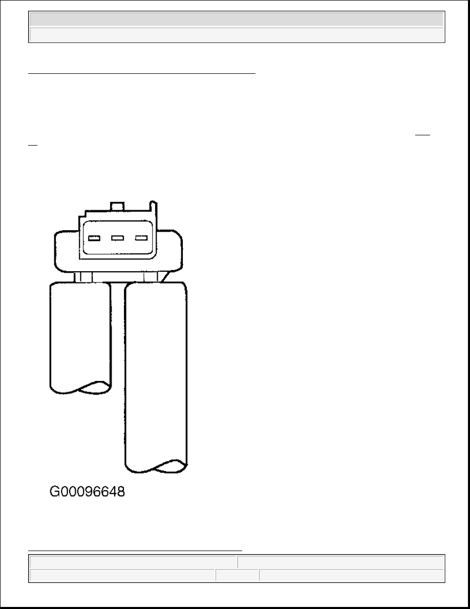


Fig. 75: Identifying Remote Mounted DPFE EGR Sensors
Courtesy of FORD MOTOR CO.
 

Differential Pressure Feedback EGR Sensor (Tube Mounted) 

Tube mounted DPFE EGR sensor is identical in operation as remote mounted larger metal or plastic DPFE 
sensors and uses a one volt offset. HI and REF hose connections are marked on underside of sensor. See Fig. 
76
 . 

Fig. 76: Identifying Tube Mounted DPFE EGR Sensor


2003 Ford Pickup F150 

2003 ENGINE PERFORMANCE Theory & Operation - CNG, Flex-Fuel & Gasoline


Courtesy of FORD MOTOR CO. 

EGR Vacuum Regulator Solenoid 

Vacuum regulator solenoid is an electromagnetic device used to regulate vacuum supply to the EGR valve. 
EGR vacuum regulator solenoid contains a coil which magnetically controls the position of a disk to regulate 
the vacuum. As the duty cycle to coil increases, vacuum signal passed through the EGR vacuum regulator 
solenoid to the EGR valve also increases. Vacuum not directed to the EGR is vented to atmosphere. At zero 
percent duty cycle (no electrical signal applied), EGR vacuum regulator solenoid allows some vacuum to pass, 
but not enough to open EGR valve. 

EGR Valve 

EGR valve in the DPFE EGR system is a conventional, vacuum actuated EGR valve. The valve increases or 
decreases flow of exhaust gas recirculation. As vacuum applied to EGR valve diaphragm overcomes spring 
force, valve begins to open. As vacuum signal weakens, at 1.6 in. Hg (5.4 kPa) or less, spring force closes 
valve. EGR valve is fully open at about 4.5 in. Hg (15 kPa). Since EGR flow requirement varies greatly, 
providing service specifications on flow rate is impractical. The OBD-II system monitors EGR valve function 
and triggers a DTC if test criteria is not met. EGR valve flow rate is not measured directly as part of field 
diagnostic procedures. 

Orifice Tube Assembly 

Orifice tube assembly is the section of tubing connecting exhaust system to intake manifold. Orifice tube 
provides a flow path for exhaust gas to intake manifold. The orifice tube contains a metering orifice and 2 
pressure pick-up tubes. See Fig. 77 . The metering orifice creates a measurable pressure drop across it as EGR 
valve opens and closes. The pressure differential across the orifice is picked up by DPFE EGR sensor which 
provides feedback to PCM. 


2003 Ford Pickup F150 

2003 ENGINE PERFORMANCE Theory & Operation - CNG, Flex-Fuel & Gasoline


Fig. 77: Identifying EGR Orifice Tube Assembly 
Courtesy of FORD MOTOR CO. 

ELECTRIC EGR MOTOR SYSTEM 

Electric EGR (EEGR) motor/valve system uses exhaust gas recirculation to control Oxides of Nitrogen (NOx) 
emissions just like vacuum operated systems. The difference is the way in which exhaust gas is controlled. 
Advantages to this type of system are:  

z

EEGR valve is activated by an electric stepper motor not a vacuum motor. It is located at rear of engine 
block.  

z

No vacuum diaphragm is used.  

z

No DPFE sensor is used.  

z

No Orifice Tube Assembly is used.  

z

No EGR vacuum regulator solenoid is used.  

z

A new MAP sensor is used. A TMAP is used, but temperature function is not used at this time. TMAP is 
located on top of valve cover.  

z

Engine coolant is routed through the assembly, extending durability of electric motor.  

EEGR system consists of an electric EGR motor/valve integrated assembly, a PCM, TMAP sensor and 
connecting wiring. The following list of components and their specific operation corresponds to numbers in 


2003 Ford Pickup F150 

2003 ENGINE PERFORMANCE Theory & Operation - CNG, Flex-Fuel & Gasoline


illustration. See 

Fig. 78

 .  

1. EEGR system receives signals from Engine Coolant Temperature (ECT) or Cylinder Head Temperature 

(CHT) sensor, Throttle Position (TP) sensor, Mass Airflow (MAF) sensor, Crankshaft Position (CKP) 
sensor and Thermal Manifold Absolute Pressure (TMAP) sensor to provide information on engine 
operating conditions to PCM. Engine must be warm, stable and running at a moderate load and engine 
speed (RPM) before EEGR system is activated. PCM will deactivate EGR during idle, extended Wide 
Open Throttle (WOT), or whenever a failure is detected in an EEGR component or EGR required input.  

2. PCM calculates desired amount of EGR for a given set of engine operating conditions.  

3. PCM in turn will output signals to EEGR motor to move (advance or retract) a certain number of discrete 

steps. Electric stepper motor will directly actuate EGR valve, independent of engine vacuum. EGR valve 
is commanded from 0-52 discrete increments or "steps" to move EGR valve from a fully closed to full or 
partially open position. The position of EGR valve determines EGR flow. 

4. TMAP sensor is used to measure variations in manifold pressure as exhaust gas recirculation is 

introduced into intake manifold. Variations in EGR being used will correlate to TMAP signal. Increasing 
EGR will increase manifold pressure values.  

EEGR valve is a water cooled motor/valve assembly. See Fig. 79 and Fig. 80 . The motor is commanded to 
move in 52 discrete steps as it acts directly on EGR valve. Position of valve determines rate of EGR flow. The 
built in spring works to close valve against motor opening force. 

Fig. 78: Identifying Electric EGR Motor System Components & Circuits (1 Of 2) 
Courtesy of FORD MOTOR CO. 

NOTE:

A TMAP is used, but temperature function is not used at this time.


2003 Ford Pickup F150 

2003 ENGINE PERFORMANCE Theory & Operation - CNG, Flex-Fuel & Gasoline


Content   ..  1642  1643  1644  1645   ..