Ford F150 Pickup. Manual - part 1571


  Index      Ford     Ford F150 Pickup - service and repair manual 2003 year


Search            


Content   ..  1569  1570  1571  1572   ..


Ford F150 Pickup. Manual - part 1571
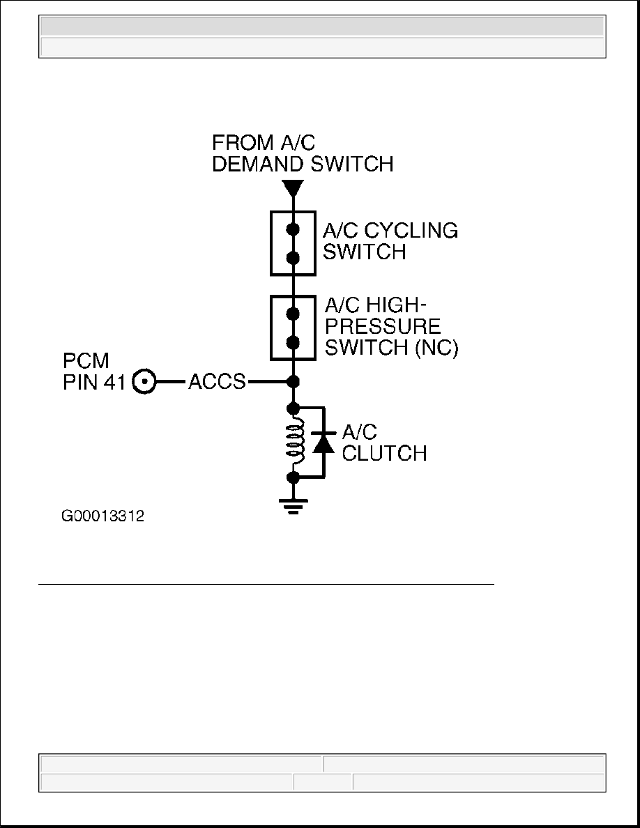


Fig. 346: Identifying ACCS Circuits & Connector Terminals (Econoline Except 4.2L) 
Courtesy of FORD MOTOR CO. 


2003 Ford Pickup F150 

2003 ENGINE PERFORMANCE Self-Diagnostics - CNG, Flex-Fuel & Gasoline


Fig. 347: Identifying ACPSW & ACCS Circuits & Connector Terminals (Explorer Sport, Explorer Sport 
Trac & Ranger)
 
Courtesy of FORD MOTOR CO. 

Fig. 348: Identifying ACPSW & ACCS Circuits & Connector Terminals (Aviator, Explorer & 
Mountaineer)
 
Courtesy of FORD MOTOR CO. 


2003 Ford Pickup F150 

2003 ENGINE PERFORMANCE Self-Diagnostics - CNG, Flex-Fuel & Gasoline


Fig. 349: Identifying ACCS Circuits & Connector Terminals (Crown Victoria, Grand Marquis, Town 
Car & Windstar)
 
Courtesy of FORD MOTOR CO. 

A/C CLUTCH RELAY LOCATIONS 

Testing 

1) For KOEO & KOER Only DTCs P0645 & P1460: Verify ACCS PID Is OFF 
DTC P0645 or P1460 is set when an excessive current draw is detected when PCM grounds Wide Open 
Throttle A/C Cut-Off (WAC) circuit, or voltage is not detected on A/C clutch relay circuit when PCM 
interrupts ground on A/C clutch relay circuit. Possible causes are: 

z

Open Or Shorted A/C clutch relay Circuit  

z

Faulty A/C clutch relay (Or CCRM)  

z

Open VPWR Circuit To A/C clutch relay  

z

Faulty PCM  

If A/C or defroster was on during self-test, turn system off and repeat self-test. Ensure A/C and defroster 
are off during self-test. If KOEO or KOER DTC P1460 is present, start engine and allow to idle. Using 
scan tool, access ACCS PID from PID/DATA MONITOR & RECORD menu. If ACCS PID indicates 

Application

Location

Crown Victoria & Grand Marquis

In Relay Center, On Left Side Of Engine Compartment

LS & Thunderbird

In Auxiliary Junction Box, On Left Side Of Engine Compartment

All Others

In Battery Junction Box, In Engine Compartment

NOTE:

For additional testing information, see DIAGNOSTIC AIDS.

NOTE:

Ensure A/C and defroster were off during KOEO and/or KOER self-test. If 
vehicle is not equipped with A/C, disregard DTC P1460. DTC P1460 can be 
set if A/C or defroster were on during KOEO or KOER self-test.


2003 Ford Pickup F150 

2003 ENGINE PERFORMANCE Self-Diagnostics - CNG, Flex-Fuel & Gasoline


OFF, go to next step. If ACCS PID indicates ON, ACCS input to PCM is requesting A/C. Diagnose A/C 
ALWAYS ON under SYMPTOM TESTS in appropriate A/C-HEATER SYSTEMS article in AIR 
CONDITIONING & HEATING. 

2) Check VPWR Voltage To A/C Clutch Relay 
 
Turn ignition switch to OFF position. Remove A/C clutch relay. For A/C clutch relay locations, refer to 
A/C CLUTCH RELAY LOCATIONS table. Turn ignition switch to ON position. Using a DVOM, 
measure voltage between chassis ground and VPWR cavity at A/C clutch relay. See Fig. 339-Fig. 341 . If 
voltage is more than 10.5 volts, go to next step. On LS and Thunderbird, if voltage is 10.5 volts or less, 
go to TEST B, step 5), or repair open in VPWR (or IGN RUN) circuit (all others). See AIR 
CONDITIONING under SYSTEM WIRING DIAGRAMS in ELECTRICAL. Start engine and allow to 
idle. Turn A/C on and wait 15 seconds. Turn A/C off and repeat QUICK TEST to verify repair. 

3) Check A/C Clutch Relay 
Turn ignition switch to OFF position and proceed as follows: 

z

ISO Mini Relay 
 
Measure resistance between relay terminal No. 85 and 86. Resistance should be 50-100 ohms. 
Measure resistance between terminals No. 85 and all other relay terminals. Resistance should be 
more than 10 k/ohms. See Fig. 306

z

ISO Micro Relay 
 
Measure resistance between relay terminal No. 1 and 2. Resistance should be 100-150 ohms. 
Measure resistance between terminals No. 1 and all other relay terminals. Resistance should be 
more than 10 k/ohms. See Fig. 307.  

On either relay, if resistance is as specified, go to next step. If relay resistance is not as specified, replace 
A/C clutch relay. Start engine and allow to idle. Turn A/C on and wait 15 seconds. Turn A/C off and 
repeat QUICK TEST to verify repair. 

4) Check A/C Clutch Relay Circuit For Short To PWR In Harness 
 
Turn ignition switch to OFF position. Disconnect PCM connector(s). Inspect connector for loose, 
damaged or corroded terminals. Repair as necessary. Turn ignition switch to ON position. Using a 
DVOM, measure voltage between chassis ground and A/C clutch relay circuit at A/C clutch relay cavity. 
See Fig. 306 or Fig. 307 and Fig. 339-Fig. 341 . If voltage is less than one volt, go to next step. If voltage 
is one volt or more, repair short to PWR in A/C clutch relay circuit. Start engine and allow to idle. Turn 
A/C on and wait 15 seconds. Turn A/C off and repeat QUICK TEST to verify repair. 

5) Check A/C Clutch Relay Circuit For Short To Ground In Harness 

NOTE:

Different applications will use an ISO micro relay or ISO mini relay for a 
A/C clutch relay. For relay identification, refer to illustrations. See Fig. 306 
or Fig. 307 .


2003 Ford Pickup F150 

2003 ENGINE PERFORMANCE Self-Diagnostics - CNG, Flex-Fuel & Gasoline


Content   ..  1569  1570  1571  1572   ..