Ford Fiesta (1989-1995). Manual - part 27
body, then measure the distance between the
gasket and the step on the float.
17 If the measurement is not as specified,
adjust by bending the tag on the float, then re-
check.
18 Refitting should be carried out in
accordance with paragraphs 11 to 14
inclusive.
15 Carburettor (Weber TLM) -
removal and refitting
4
Note: Refer to the warning note in Section 1
before proceeding. New gaskets will be
required when reassembling. A tachometer
and an exhaust gas analyser (CO meter) will
also be required to check the idle speed and
mixture settings on completion.
Removal
1 Disconnect the battery negative (earth) lead
(refer to Chapter 5A, Section 1).
2 Remove the air cleaner as described in
Section 2.
3 Disconnect the accelerator inner and outer
cable from the carburettor (Section 3).
4 Disconnect the choke inner and outer cable
from the carburettor (Section 6).
5 Disconnect the fuel feed hose from the
carburettor, and plug its end to avoid spillage
and prevent dirt ingress. If a crimped type
hose clip is fitted, cut this free taking care to
avoid damage to the hose.
6 Where applicable, disconnect the electrical
lead from the anti-dieseling (fuel cut-off)
solenoid, and all relevant carburettor vacuum
pipes (having labelled them for correct
subsequent refitting).
7 Remove the two Torx head screws securing
the carburettor to the inlet manifold, then
withdraw it from the vehicle (see illustration).
Refitting
8 Clean the inlet manifold and carburettor
gasket mating faces.
9 Refit in the reverse order of removal. Fit a
new gasket, and tighten the retaining screws
securely. Ensure that the fuel supply hose
connection to the carburettor is securely
fitted, using a new screw type retaining clip.
10 Reconnect the accelerator cable, and
adjust it as described in Section 3.
11 Reconnect the choke cable, and adjust it
as described in Section 6.
12 Refer to Section 2 and refit the air cleaner.
13 When the battery is reconnected, start
and warm up the engine then check the idle
speed and mixture settings as described in
Chapter 1.
16 Accelerator pump diaphragm
(Weber TLM carburettor) -
removal and refitting
4
Note: Refer to the warning note in Section 1
before proceeding.
Removal
1 Remove the carburettor as described in
Section 15 and place it on a clean flat work
surface.
2 Remove the accelerator pump cover
retaining screws and detach the cover.
3 Withdraw the diaphragm and spring. Check
the diaphragm for damage, and renew if
evident.
Refitting
4 Clean the carburettor and cover mating
faces.
5 Refit the spring and diaphragm to the
carburettor, aligning the diaphragm with its
cover retaining screw holes. Position the
actuating lever on its cam, then carefully
press the cover against the diaphragm and
secure with its retaining screws.
6 Refit the carburettor as described in
Section 15.
17 Carburettor (Weber TLM) -
dismantling, cleaning,
inspection and reassembly
4
Note: Refer to the warning note in Section 1
before proceeding. Check parts avail-
ability before dismantling. If possible, obtain
an overhaul kit containing all the relevant
gaskets, seals, etc, required for reassembly
prior to dismantling the carburettor.
Dismantling
1 Remove the carburettor as described in
Section 15 and place it on a clean flat work
surface.
2 Clean the exterior of the carburettor, then
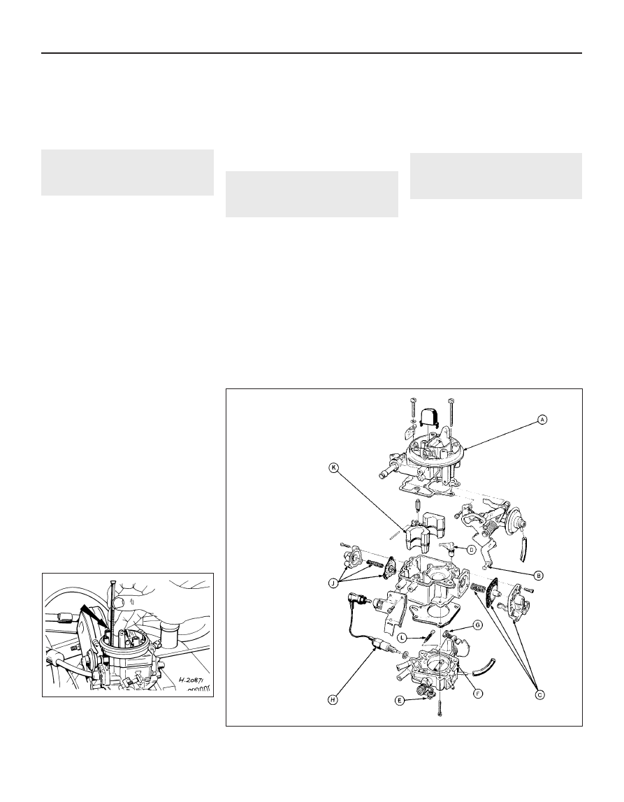
undo the two retaining screws and lift off the
upper carburettor body (see illustration).
3 Remove the float and needle valve from the
carburettor upper body, as described in
Section 14.
4 Remove the accelerator pump components
4A•8 Fuel system – carburettor engines
17.2 Exploded view of the carburettor (Weber TLM)
15.7 Removing one of the two Torx head
screws (arrowed) securing the carburettor
to the inlet manifold (Weber TLM
carburettor)
1595Ford Fiesta Remake
A Upper body
B Choke mechanism
C Accelerator pump
assembly
D Accelerator pump
discharge tube
E Fast-idle speed
adjusting screw
F Throttle housing
G Idle speed adjusting
screw
H Anti-dieseling (fuel
cut-off) solenoid
J Power valve assembly
K Float
L Idle mixture adjusting
screw