Ford Fiesta (1989-1995). Manual - part 20
2 If not already done, remove the inlet and
exhaust manifolds with reference to the
relevant Part of Chapter 4.
3 Proceed as follows according to engine
type.
HCS engines
4 Valve removal should commence with No 1
valve (nearest the timing chain end).
5 To remove the valve springs and valves
from the cylinder head, a standard valve
spring compressor will required. Fit the spring
compressor to the first valve and spring to be
removed. Take care not to damage the valve
stem with the compressor, and do not over-
compress the spring, or the valve stem may
bend. When tightening the compressor, it may
be found that the spring retainer does not
release and the collets are then difficult to
remove. In this instance, remove the
compressor, then press a piece of tube (or a
socket of suitable diameter) so that it does not
interfere with the removal of the collets,
against the retainer’s outer rim. Tap the tube
(or socket) with a hammer to unsettle the
components.
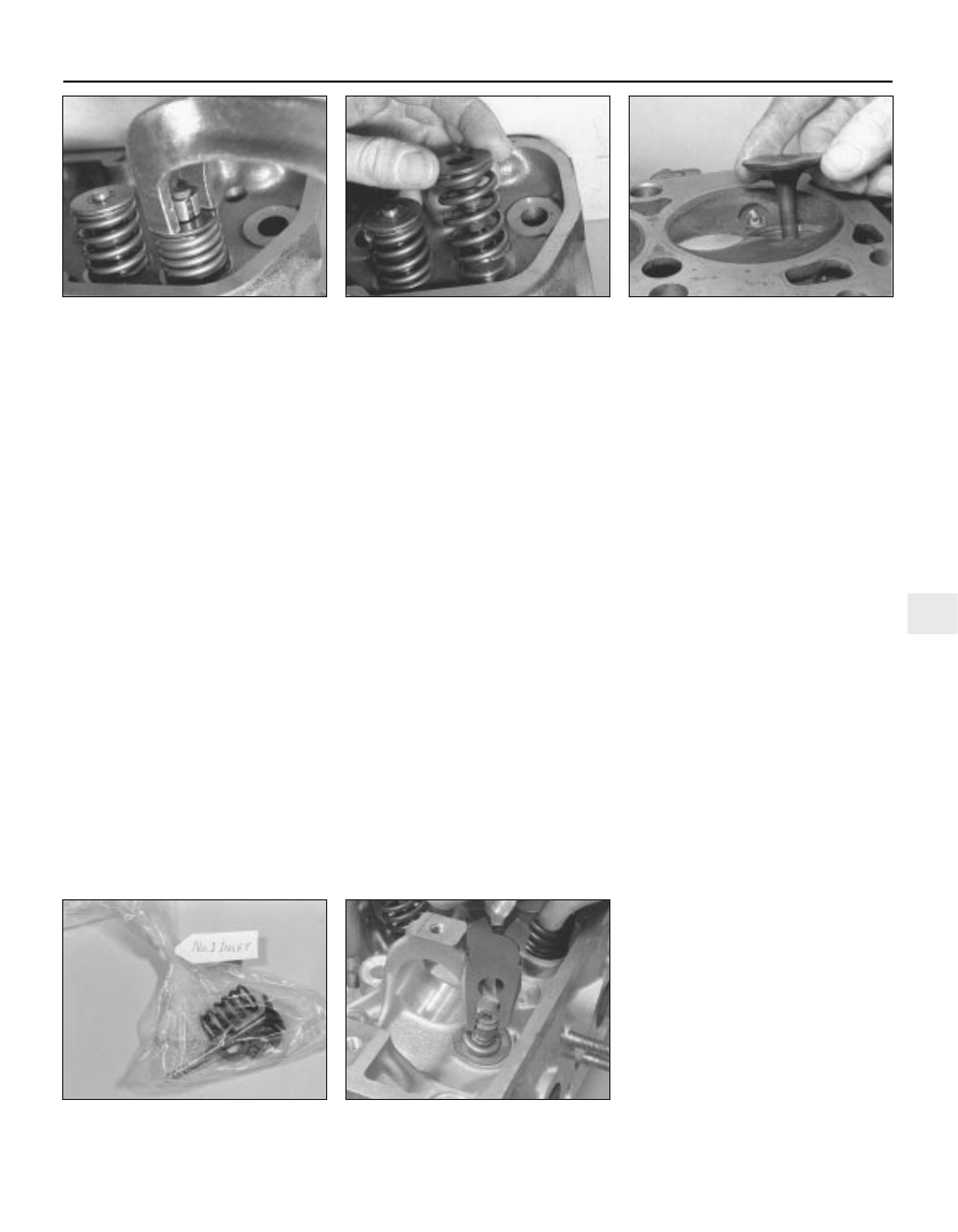
6 Refit the compressor, and wind it in to
enable the collets to be extracted (see
illustration).
7 Loosen off the compressor, and remove the
retainer and spring. Withdraw the valve from
the cylinder head (see illustrations).
8 Prise up and remove the valve stem seal.
9 Repeat the removal procedure with each of
the remaining seven valve assemblies in turn.
As they are removed, keep the individual
valves and their components together, and in
their respective order of fitting, by placing
them in a separate labelled bag (see
illustration).
CVH and PTE engines
10 Remove the camshaft, rocker arms and
tappets as described in Part B of this Chapter,
being careful to store the hydraulic tappets as
described.
11 Valve removal should commence with
No 1 valve (nearest the timing belt end).
12 Using a standard valve spring com-
pressor, compress the valve spring (and
upper retainer) just enough to enable the split
collets to be released from the groove in the
top of the valve stem, then separate and
extract the split collets from the valve. Do not
compress the spring any further than is
necessary, or the valve stem may bend. If the
valve spring retainer does not release from the
collets as the spring is compressed, remove
the compressor, and position a piece of
suitable tube over the end of the retainer, so
that it does not impinge on the collets. Place a
small block of wood under the valve head
(with the head resting face down on the
workbench), then tap the end of the tube with
a hammer. Now refit the compressor tool, and
compress the valve spring. The collets should
release.
13 Extract the split collets, then slowly
unscrew, release and remove the compressor.
14 Withdraw the upper retainer and the valve
spring from the valve stem, then remove the
valve from the underside of the cylinder head.
Use a suitable screwdriver or pliers to prise
free and remove the valve stem oil seal from
the guide (see illustration).
15 Remove the lower retainer.
16 Repeat the removal procedure with each
of the remaining valve assemblies in turn. As
they are removed, keep the valves and their
associated components together, and in the
originally-installed order, by placing them in a
separate labelled bag (see illustration 7.9).
Zetec engines
17 Remove the camshafts and hydraulic
tappets as described in Part C of this Chapter,
being careful to store the hydraulic tappets as
described.
18 Using a valve spring compressor,
compress each valve spring in turn until the
split collets can be removed. A special valve
spring compressor will be required, to reach
into the deep wells in the cylinder head
without risk of damaging the hydraulic tappet
bores; such compressors are now widely
available from most good motor accessory
shops. Release the compressor, and lift off
the spring upper seat and spring.
19 If, when the valve spring compressor is
screwed down, the spring upper seat refuses
to free and expose the split collets, gently tap
the top of the tool, directly over the upper
seat, with a light hammer. This will free the
seat.
20 Withdraw the valve through the
combustion chamber. If it binds in the guide
(won’t pull through), push it back in, and de-
burr the area around the collet groove with a
fine file or whetstone; take care not to mark
the hydraulic tappet bores.
21 Ford recommend the use of their service
tool 21-160 to extract the valve spring lower
seat/stem oil seals; while this is almost
indispensable if the seals are to be removed
without risk of damage to the cylinder head, a
serviceable substitute can be made from a
strong spring of suitable size. Screw on the
tool or spring so that it bites into the seal, then
Engine removal and overhaul procedures 2D•13
7.7b . . . followed by the valve
7.7a Remove the valve spring retainer and
spring . . .
7.6 Compress the valve spring to remove
the collets
7.14 Prise off the valve stem oil seal
7.9 Use a labelled plastic bag to store and
identify valve components
2D
1595Ford Fiesta Remake