Ford Fiesta (1989-1995). Manual - part 8
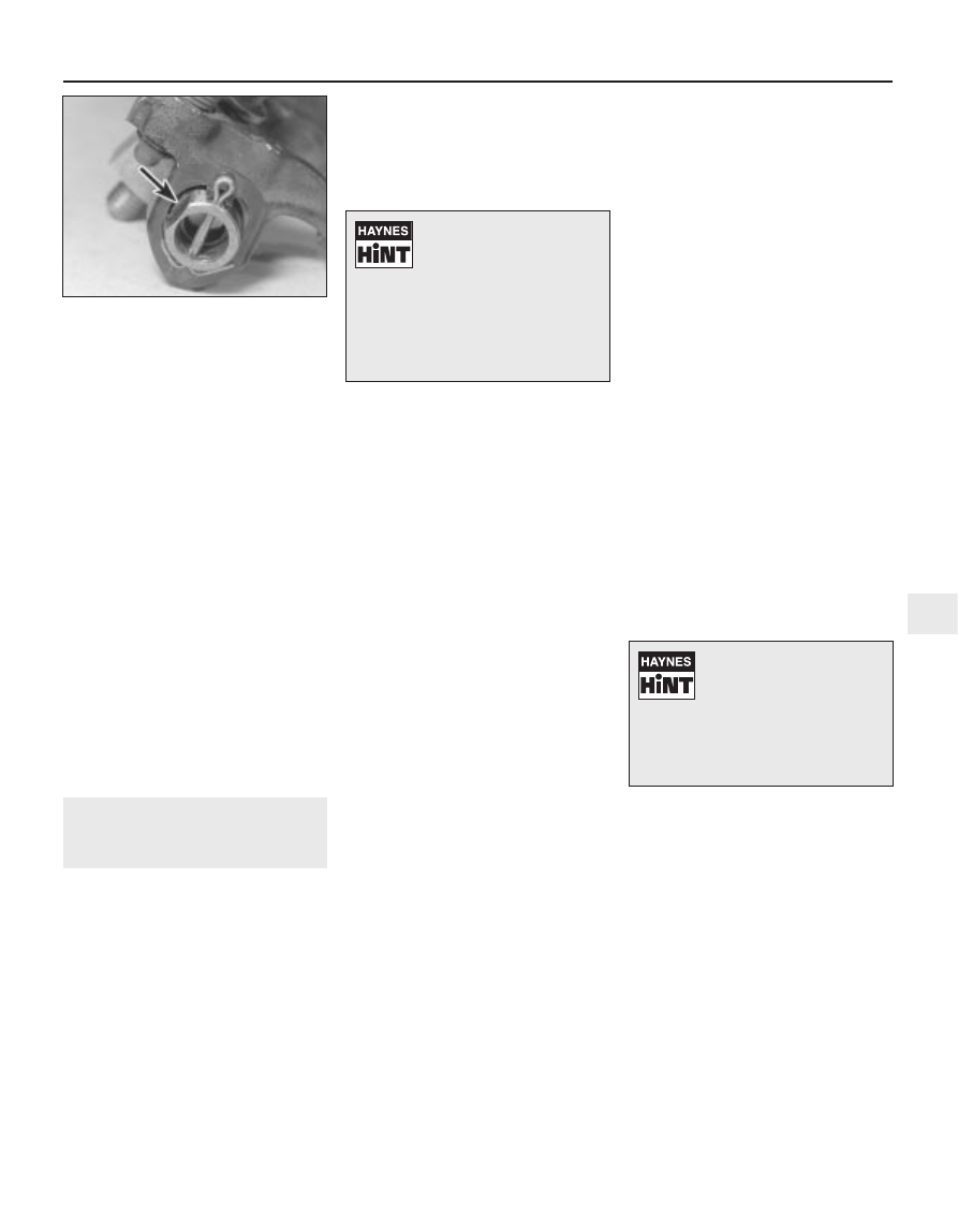
8 Reassemble in the reverse order of
dismantling. Make sure that the “flat” on the
rear end of the rocker shaft is to the same side
as the rocker arm adjusting screws (closest to
the thermostat end of the cylinder head when
fitted) (see illustration). This is essential for
the correct lubrication of the cylinder head
components.
9 Refit the rocker shaft assembly. As it is
fitted, ensure that the rocker adjuster screws
engage with their corresponding pushrods.
10 Refit the rocker shaft retaining bolts,
hand-tighten them and then tighten them to
the specified torque wrench setting. As they
are tightened, some of the rocker arms will
apply pressure to the ends of the valve stems,
and some of the rocker pedestals will not
initially be in contact with the cylinder head -
these should pull down as the bolts are
tightened to their specified torque. If for any
reason they do not, avoid the temptation to
overtighten in order to pull them into position;
loosen off the bolts, and check the cause of
the problem. It may be that the rocker adjuster
screws require loosening off in order to allow
the assembly to be tightened down as
required.
11 Adjust the valve clearances as described
in Section 5.
7
Cylinder head -
removal and refitting
3
Removal
Note: The following procedure describes
removal and refitting of the cylinder head
complete with inlet and exhaust manifolds. If
wished, the manifolds may be removed first,
as described in the relevant Part of Chapter 4,
and the cylinder head then removed on its
own.
1 On fuel injection engines, depressurise the
fuel system as described in Chapter 4, Part B.
2 Disconnect the battery negative (earth) lead
(refer to Chapter 5A, Section 1).
3 Refer to Chapter 4A or 4B as applicable
and remove the air cleaner.
4 Refer to Section 4 and remove the rocker
cover.
5 Refer to Chapter 1 and drain the cooling
system.
6 Disconnect the hoses from the thermostat
housing.
7 Disconnect the heater (coolant) hoses from
the inlet manifold and CFi unit, where
applicable.
8 Disconnect the accelerator and choke
cables as applicable (see Chapter 4A or 4B).
9 Disconnect the vacuum and breather hoses
from the carburettor/CFi unit, and inlet
manifold as applicable.
10 Disconnect the fuel feed and return lines
at the carburettor, or at the quick-release
couplings, then unclip the fuel hoses from the
inlet manifold; use rag to soak up any spilt
fuel.
11 Disconnect the HT leads from the spark
plugs and the support bracket. Unscrew and
remove the spark plugs.
12 Disconnect the electrical leads from the
temperature gauge sender, radiator cooling
fan, the engine coolant temperature sender,
and the anti-run-on (anti-dieselling) valve at
the carburettor.
13 Disconnect the remaining wiring multi-
plugs from the engine sensors at the inlet
manifold and from the oxygen sensor (where
fitted) in the exhaust manifold or downpipe.
14 On vehicles equipped with a pulse-air
system, remove the pulse-air piping and filter
assembly as described in Chapter 4E.
15 Chock the rear wheels then jack up the
front of the car and support it on axle stands
(see “Jacking and Vehicle Support”).
16 Undo the retaining nuts and bolts, and
disconnect the exhaust downpipe from the
manifold. Remove the flange gasket. (Note
that both the gasket and the joint self-locking
nuts must be renewed.) To prevent the
exhaust system from being strained, tie the
downpipe up using strong wire or a length of
cord to support it. Lower the vehicle.
17 Undo the four retaining bolts and lift clear
the rocker gear assembly from the cylinder
head.
18 Lift out the pushrods. Keep them in order
of fitting by labelling them 1 to 8, starting from
the thermostat end of the cylinder head.
Alternatively, push them through a piece of
card in their fitted sequence.
19 Progressively unscrew and loosen off the
cylinder head retaining bolts in the reverse
sequence to that shown for tightening (see
illustration 7.27a).
When they are all
loosened off, remove the bolts, then lift the
cylinder head clear and remove the gasket. If
it is stuck, tap it upwards using a hammer and
block of wood. Do not try to turn it, as it is
located by dowels; make no attempt
whatsoever to prise it free using a screwdriver
inserted between the block and head faces.
The gasket must always be renewed; it should
be noted that the cylinder head retaining bolts
may be re-used, but only once. They should
be marked accordingly with a punch or paint
mark. If there is any doubt as to how many
times the bolts have been used, they must be
renewed.
20 To dismantle/overhaul the cylinder head,
refer to Part D of this Chapter. It is normal for
the cylinder head to be decarbonised and the
valves to be reground whenever the head is
removed.
Preparation for refitting
21 The mating faces of the cylinder head and
cylinder block must be perfectly clean before
refitting the head. Use a hard plastic or wood
scraper to remove all traces of gasket and
carbon; also clean the piston crowns. Take
particular care during the cleaning operations,
as aluminium alloy is easily damaged. Also,
make sure that the carbon is not allowed to
enter the oil and water passages - this is
particularly important for the lubrication
system, as carbon could block the oil supply
to the engine’s components. Using adhesive
tape and paper, seal the water, oil and bolt
holes in the cylinder block.
22 Check the mating surfaces of the cylinder
block and the cylinder head for nicks, deep
scratches and other damage. If slight, they
may be removed carefully with a file, but if
excessive, machining may be the only
alternative to renewal.
23 If warpage of the cylinder head gasket
surface is suspected, use a straight-edge to
check it for distortion. Refer to Part D of this
Chapter if necessary.
24 Clean the threads of the cylinder head
bolts or fit new ones (as applicable) and clean
out the bolt holes in the block. Screwing a bolt
into an oil-filled hole can (in extreme cases)
cause the block to fracture, due to the
hydraulic pressure.
Refitting
25 Check that the new cylinder head gasket
is the same type as the original, and that the
“TOP” (or “OBEN”) marking is facing
upwards. Locate the new cylinder head
HCS engine in-car repair procedures 2A•5
6.8 Flat on the rocker shaft (arrowed) to
same side as rocker arm adjusting screws
2A
1595Ford Fiesta Remake
Whenever you disconnect
any vacuum lines, coolant or
emissions hoses, wiring
connectors and fuel lines,
always label them clearly, so that they
can be correctly reassembled. Masking
tape and/or a touch-up paint applicator
work well for marking items. Take
instant photos, or sketch the locations
of components and brackets.
To prevent carbon entering
the gap between the pistons
and bores, smear a little
grease in the gap. After
cleaning each piston, use a small brush
to remove all traces of grease and
carbon from the gap, then wipe away
the remainder with a clean rag.