Citroen C6 (2011 year). Manual - part 7
 

  Index      Citroen     Citroen C6 - service manual 2011 year in english


Search            


Content   ..  5  6  7  8   ..


Citroen C6 (2011 year). Manual - part 7


95

III

Programming the heater

Activation – deactivation 

Stopping the heater

You should programme your depar-

ture time so that the system can

automatically calculate the opti-

mum start time for the heater.

Programming your 

departure time

The "HTM" symbol stays on.

P R O G R A M M A B L E   H E AT I N G

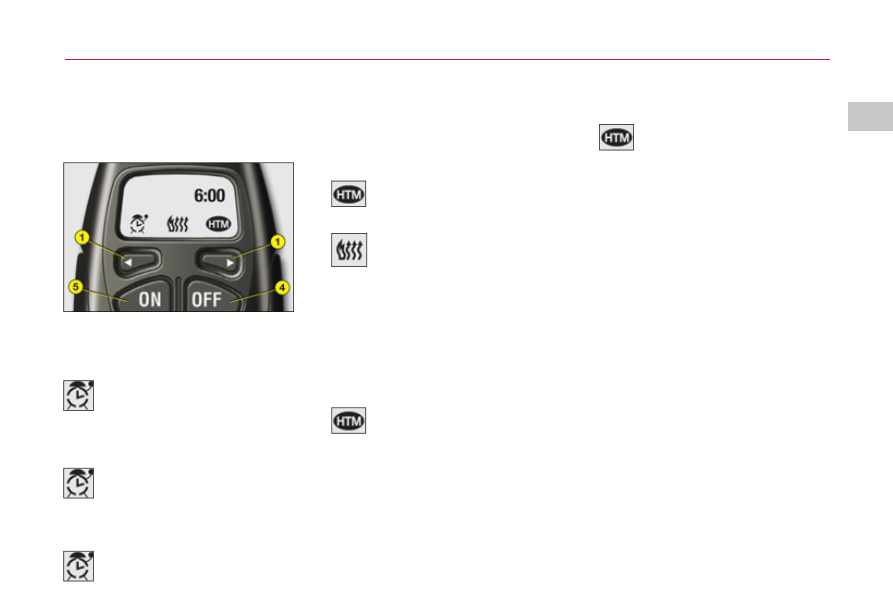
Press buttons to display the pro-

gramme time.

This symbol is displayed.

After displaying the programme

time, within 10 seconds press but-

tons 4 and 5 simultaneously.

This symbol fl ashes.

Adjust the time by pressing buttons 1

and press buttons and 

4

simultane-

ously to store the setting.

This symbol is displayed (constant).

When the signal has been 

received, the "OK" message 

is displayed together with the 

"HTM" symbol.

This symbol  is  displayed 

when the heater starts.

After displaying the programme time 

using buttons 1, press button 5 (ON) 

until the "OK" message appears.

HTM:  Heat  Thermo  Management 

(heater control system).

To cancel a programme, press but-

ton 4 (OFF) until the "OK" message 

appears

The "HTM" symbol goes off.

If the "FAIL" message appears 

during these operations, this indi-

cates that the signal was not 

received.
Go to a different location and then 

repeat the procedure.

Press button 5 (ON).

Modifi cation of the heating 

level

The system offers 5 levels of heat-

ing (C1, the lowest level, to C5, the

highest level).
After displaying the heating level

using  buttons  1, press buttons 4

and simultaneously.
The letter "C" fl ashes.
Adjust the level of heating using

buttons 1.
Press  buttons and  5  simultane-

ously to store the level setting cho-

sen. The  letter  "C" is displayed

(constant).

The  factory settings are replaced

by the new values entered. The

times programmed are memorised

until the next modifi cation.
When the departure time is acti-

vated, it is not possible to modify

the heating level. The departure

time should fi rst be deactivated.

96

III

Replacing the battery

The remote control  is powered

by a 6V-28L battery cell, which is

included.
Information appears on the screen

when this battery should be replaced.
Unclip the casing and replace the

battery.
The  remote  control must then  be

re-initialised, as described on this

page.
Do not discard old batteries; take

them to an approved recycling

point.

Re-initialisation of the 

remote control

Always switch off the program-

mable heating while refuelling in

order to avoid the risk of fi re or 

explosion.
To  avoid the risk  of intoxication

or asphyxiation, the program-

mable heating should not be

used, even for a short time, in

an enclosed space such as a

garage, or workshop without

exhaust gas extraction.
Do not park the vehicle over 

infl ammable materials (dry grass,

dead leaves, papers…), as there

is a risk of fi re.
The programmable heating sys-

tem is supplied by the vehicle’s

fuel tank. Before using it, ensure

that there is suffi cient fuel in the

tank. If the low fuel warning lamp

is on we strongly recommend

that  you do not programme the

heating to come on.

P R O G R A M M A B L E   H E AT I N G

If the battery is disconnected or 

replaced, the remote control must 

be re-initialised.
After switching on, within fi ve sec-

onds press button 4  (OFF) for 

1 second.
If the operation is successful, the 

"OK" message appears in the 

remote control screen.
If not, the "FAIL" message appears. 

Repeat the procedure.
As a secondary advantage, use of 

your programmable heating  sys-

tem allows it to be used to pre-heat 

the passenger compartment.

97

III

C

D

R E A R   S E AT S

REAR HEAD RESTRAINTS

The rear head restraints have two

positions:

A stowed position for when the

seat is not occupied.
A deployed position for safety 

of passengers, locking into

place including for a forward-

facing child seat.

To lower the head retraints, press

on the tab at the base.
To raise them, pull them upwards

to their maximum height, pressing

the unlocking button.

CONTROLS FOR PACK

LOUNGE HEATED SEATS

The Pack Lounge seats can be heated

independently of each other.
Use the controls located  on the

outside of the seats to select any

of three heating levels:

CONTROLS FOR HEATED 

SEATS IN A BENCHSEAT

The rear seats can be heated inde-

pendently of each other.
Use the controls located  under 

the rear storage tray to activate the 

heating.

0: Off.
1: Slight heat.
2: Medium heat.
3: Maximum heat.

The seat temperature adjusts auto-

matically.
Note: The heated seats only ope-

rate when the engine is running.

98

III

1

2

R E A R   S E AT S

FOLDING BENCHSEAT

The whole or just part of the benchseat can be folded. It is necessary to 

remove the head restraints.

Seat cushion

Use the strap to lift the seat cushion, then rest it against the front seat back-

rests.  When repositioning  the seat cushion, make sure that the seat belt 

buckles are correctly in place.

FLAP FOR TRANSPORT OF

LONG OBJECTS

A  fl ap in the backrest, located to

the rear of the armrest, facilitates

the carrying of long objects.
Before installing any long objects,

fold the interior  blind  and then

make  sure  that the  loads  are

properly secured, not obstructing

the movements of the gear lever.
This fl ap can be concealed by means

of a foldable cover with a tab.

99

III

A

B

C

D

R E A R   S E AT S

Seat cushion folded.
Stow the head restraints.
Press the  control A  located  at the

end of the backrest and fully tilt

forwards.
The  benchseat  backrest  can  be

folded in two sections. When you

reposition the backrest, make sure

that it locks in place.

Your vehicle's boot can be kept 

isolated from the passenger com-

partment.
To lock the access to the boot:

1. Place the benchseat in its 

correct position.
The red warning lamp on

control should no longer be

visible.

2. Insert the ignition key in the

lock.

3. Lock it.

Before moving the seats

So as to avoid damaging the seat belts by  jamming them, take

care to keep them to the sides of the backrest.

LOCKING/UNLOCKING OF THE ACCESS INTO THE BOOT VIA 

THE REAR BENCHSEAT

REAR CENTRAL SEAT BELT

For easier opening of the seat belt

cover D, you should fi rst raise the

central head restraint.
Insert the fi rst  fastening C into the

front left hand (black) buckle, then

insert the second fastening B  into

the front right hand buckle.

100

III

B

A

PA C K   L O U N G E   S E AT S

ANGLE OF THE REAR 

LATERAL HEAD

RESTRAINTS

To alter the angle of the rear lateral

head restraints, lift them then tilt

them upwards.

LONGITUDINAL

ADJUSTMENT OF THE 

FRONT PASSENGER'S 

SEAT

For more room for the rear passen-

ger, it is possible for the front pas-

senger's seat to be slid forward

from the rear seat position.
To slide the front passenger's seat

forward, press on the control at

the centre of the armrest.
Note: This control is not active if 

adjustments are being made simul-

taneusly at the front.
The front passenger's seat will slide

forward  for as long as you keep

control pressed. It stops immedi-

ately you release control B.
Note: Use of the child safety deac-

tivates button B. See "Windows".

ADJUSTING THE SEAT AND

ITS BACKREST

You can adjust the longitudinal 

position of the seat and the angle

of its backrest simultaneously 

using the control A.

IMPORTANT

Pack Lounge seats  cannot  be 

folded.
Note: 
Use of the child safety deac-

tivates button A. See "Windows".

101

III

A

A I R B A G S

AIRBAG EQUIPMENT

Your vehicle has:

A driver's front airbag.
A driver's knees airbag.
A front passenger's airbag 

which can be deactivated.
Front lateral airbags.
Front and rear curtain airbags.
Rear lateral airbags.

Deployment of your airbags is

dependent on the degree of vio-

lence of the collision.


REACTIVATING THE FRONT

PASSENGER'S AIRBAG

Do not forget to reactivate the

function.
For that:

With the ignition switched off, 

insert the key into the switch A.
Turn the key to the "ON"

position, the airbag is

activated.
The warning lamp in the

instrument panel lights up for a 

few seconds when you switch

on the ignition.

Note: It is compulsory to wear the

seat belt.
Never  deactivate the passenger's

airbag when a passenger is present

(unless a child in a rear-facing child

seat).

FRONT PASSENGER'S

AIRBAG DEACTIVATION

In order to be able to use a rear-facing 

child seat in the front passenger's seat 

position,  it  is  imperative to deactivate 

the passenger's airbag.
For that:

With the ignition switched off,

insert the key into the switch A.
Turn the key to the "OFF"

position, the passenger's 

airbag is deactivated.
The front passenger's airbag 

deactivation warning lamp,

in the instrument panel, lights

up when you switch on the

ignition.

102

III

Passenger’s airbag OFF

Refer to the instructions present on 

both sides of the passenger’s sun 

visor. 

In the front passenger's seat position, it is imperative to deactivate the front passenger's airbag if 

you are installing a "rear-facing" child seat there.
Otherwise the child risks being killed or seriously injured should the airbag deploy.

A I R B A G S

103

III

C H I L D   R E S T R A I N T S

CHILD SEATS SECURED BY 

MEANS OF THE VEHICLE 

SEAT BELT

In conformity with European law,

this table shows  you the possibili-

ties  for the installation  of  univer-

sally approved child seats using a

seat belt, depending on the weight

of the child.
Consult "User Precautions", chap-

ter on "Child Safety" at the end of 

this handbook, in order to ensure

that you are installing your child in

conditions of maximum safety.

Seat position(s)

Weight of child

Up to 10 kg

and up to 13 kg

(groups 0 and 0+)

9 - 18 kg 

(group 1)

15 - 25 kg

(group 2)

22 - 36 kg

(group 3)

Front passenger’s (a)

U (R)

U (R)

U (R)

U (R)

Lateral rear

U

U

U

U

Central rear

L1

X

L3

L3

In the front passenger's seat position, it is imperative to deactivate the front passenger's airbag if 

you are installing a "rear-facing child seat" there. Otherwise the child risks being killed or seriously 

injured should the airbag deploy.
Take care to comply with the fi tting instructions given in the child seat manufacturer’s installation 

guide.

U: Seat position suitable for the installation of a universal rear-facing child

seat and a universal forward-facing child seat position.
U (R): Seat position suitable for installation of a universal rear-facing child

seat and of a forward-facing seat. The vehicle seat should be adjusted to

the highest position.
(a): In the front passenger's seat position, it is imperative to deactivate the

front passenger's airbag if you are installing a "rear-facing child seat" there.

Otherwise the child risks being killed or seriously injured should the airbag

deploy.
Before placing your child in the front passenger’s seat position, consult the

legislation currently in force in your country on the carrying of children in this

position.
L-:  Only the child seats indicated may be installed in the seat position

concerned (depending on country).
X: Position not suitable for installation of a child seat of the weight  group

indicated.

104

III

a

b

a

b

Pack Lounge seats

 ISOFIX ANCHORING

POINTS AND THE  ISOFIX

FASTENING SYSTEM

Your vehicle  is type-approved

according to new  

ISOFIX direc-

tives. The  lateral rear  seats  of 

your vehicle are each equipped

with regulation  ISOFIX anchoring

points.
Incorrect installation of a child seat

in a vehicle compromises  protec-

tion of the child in the event of a col-

lision. The  ISOFIX system enables

you to minimise the risks posed by

incorrect  fi tting. The  

ISOFIX  fas-

tening system gives you a conven-

ient, strong and reliable fi tting for a

child seat in your vehicle.

Benchseat

The  ISOFIX fastening 

system

The  ISOFIX system features 3 rings

for each lateral rear seat position:

Two bottom rings and b

located between the backrest

and the seat cushion. These 

are about 28 cm apart,

concealed in the case of a 

benchseat under a fl ap with the 

logo  ISOFIX.
One top ring c fi xed on the rear 

shelf, concealed under a fl ap

with the logo  TOP TETHER

behind the head restraint.

The  ISOFIX child seat

fastening system

 ISOFIX child seats have two latches

which are easy to secure on the two

bottom rings and b.
Some  ISOFIX child seats also have

a top belt which is for attaching on

the  ISOFIX top ring c.
To attach  the top belt, raise the

head restraint of the vehicle seat,

then pass the buckle between the

two supports. Next fi x  the  buckle

on the top ring c  and  tension the

top belt.
This  fi xing  system is intended for 

children weighing up to 18 kg.
The  ISOFIX child seats that can be

installed in your vehicle are given

in the table opposite.

C H I L D   R E S T R A I N T S

105

III

TABLE SUMMARISING THE INSTALLATION OF  ISOFIX CHILD

SEATS

In compliance with European legislation (ECE 16), this table indicates which 

of the  ISOFIX child seats can be installed in seat positions in your vehicle 

that are equipped with  ISOFIX anchoring points.
For  ISOFIX universal and semi-universal child seats, the  ISOFIX size class, 

defi ned by a letter from A to G, is shown on the child seat to the right of the  

ISOFIX logo.
When an ISOFIX child seat is installed on a Lounge seat, the Lounge 

seat must be adjusted to the most upright position.

RECOMMENDED ISOFIX

CHILD SEAT

The ISOFIX child seat recom-

mended for your vehicle is the

ISOFIX RÖMER Duo Plus

y

. It

is  available from the  CITROËN

dealer network.
It is equipped with a top belt and so

is approved as an "ISOFIX univer-

sal" child seat, size class B1. It is

essential to use the top belt.
This  ISOFIX child seat can also be

installed in seat positions that are

not equipped with  ISOFIX anchor-

ing points. In this case, it is com-

pulsory to secure it to the vehicle

seat by means of the vehicle seat

belt.

IUF: Seat position suitable for installation of an  ISOFIX universal child seat.  ISOFIX "forward-facing" child 

seats equipped with a top belt for attaching on the top ring in the vehicle's  ISOFIX seat positions.
IL-SU: Seat position suitable for installation of an  ISOFIX semi-universal child seat.  ISOFIX "forward-

facing" child seats equipped with a bar,  ISOFIX "rear-facing" child seats, or  ISOFIX shell seats equipped 

with either a top belt or a bar.

Weight of child/Age given as a guide

Up to 10 kg

(group 0)

Up to around 

6 months

Up to 10 kg 

and up to 13 kg

(groups 0 and 0+)

Up to around 

1 year old

9 - 18 kg (group 1)

From approx. 1 to 3 years

Type of  ISOFIX

child seat

Shell

"Rear-facing"

"Rear-

facing"

"Forward-

facing

 ISOFIX size class

F

G

C

D

E

C

D

A

B

B1

ISOFIX 

lateral 

rear 

seats

ISOFIX 

universal

and semi-

universal

child

seats

-

IL-SU

IL-SU

IUF

IL-SU

C H I L D   R E S T R A I N T S

106

III

A

S U S P E N S I O N   W I T H   E L E C T R O N I C A L LY 

C O N T R O L L E D   S P R I N G I N G   A N D   D A M P I N G

Active suspension with piloted

damping and fl exibility automati-

cally and instantaneously adjusts

the dampers to your driving style,

as  well  as  to the  condition  of the

road surface, to achieve the maxi-

mum comfort  for  you and your 

passengers, as well as improved

roadholding.

Normal mode: This functioning mode fi lters the unevenness of the road

surface with the suppleness of the damping to produce a superlative ride.
Sport mode: a press on button gives you a suspension that is more adapted

A

to a sporty style of driving. This functioning mode makes the damping fi rmer,

for enhanced control of the vehicle body movements.

This symbol is displayed on your instrument panel.

SIGNALLING

In the standard situation, button A is not lit up by day, it only illuminates 

at night.
In sport mode, after you press button A, the latter lights up in orange, 

day or night.

The mode selected is conserved until the ignition is switched off.

107

III

G R O U N D   C L E A R A N C E   A D J U S T M E N T

Position changes may only  be

made when the engine is running.

The ground clearance is adjusted

automatically. You can however 

modify the vehicle height in cer-

tain specific cases.

To change the position

Press once on one of the adjust-

ment controls. The change of 

position is indicated at the start

of the adjustment by:

A message or
Temporary display of the initial

position with the symbol for the 

position requested.

Note:  You  are  recommended  to

avoid any changing of position while

you have your foot on the brake.

Viewing of the position of the

vehicle

On completion of the adjustment

you see either a message or an

illustration of the position attained

by the vehicle, with the appropriate

symbol.


Maximum height

Changing a wheel.

Intermediate position

For an increased ground clearance.
For use on diffi cult roads when travel-

ling at reduced speed, as well as on

carpark ramps.

Normal road position

Minimum height

To facilitate loading or unloadng the

vehicle.
For workshop inspections.
Not to be used in normal driving.

For your safety if you are operating underneath the vehicle,

it is obligatory to support the vehicle with axle stands.
Display of the position requested confi rms the completion of 

the adjustment.

108

III

G R O U N D   C L E A R A N C E   A D J U S T M E N T

AUTOMATIC CORRECTION OF GROUND CLEARANCE

Your vehicle has active suspension with variable damping which is electronically controlled. This automatically regulates

the ground clearance according to the vehicle speed and the road surface conditions.

Limits on access to the 

positions

Maximum height:
Impossible if speed > 10 km/h (6 mph).
Intermediate position:
Impossible if speed > 40 km/h (24 mph).
Normal road position: Always

permitted.
Minimum height:
Impossible if speed > 10 km/h (6 mph).
Note: If the speed authorised for 

a particular position is exceeded,

the vehicle reverts automatically to

the normal road position.

Signalling of a requested

position not authorised

On the display:
The display indicates for a short 

time, via a message or by hatching 

on the requested position, that the 

adjustment is impossible.
The vehicle remains in the position 

that is authorised and the display 

confi rms this position.

Automatic variation of ground

clearance

If your speed exceeds

110 km/h (68 mph), on a 

good road, the ground 

clearance is lowered.
The vehicle reverts to the 

normal road position if the

road deteriorates or if your 

speed comes below 90 km/h

(56 mph).
When the vehicle is 

stationary the ground 

clearance is lowered to the 

parking position.

109

III

2

2

1

2

2

I N T E R I O R   L I G H T I N G

Front

INTERIOR LAMPS

1. Interior lamps

A  press on button 1  of the front

interior lamp, switches the interior 

lamps on or off.
Switching on and off is progressive

after an action on the remote control,

but immediate after a press on but-

ton 1.

Rear

2. Spotlamps

A press on one of the buttons 2

switches the corresponding spot-

lamp on or off.
These only work when the ignition 

is switched on.

Automatic lighting of the 

interior lamps

They come on when you 

remove the ignition key, unlock 

the vehicle or open a door.
They go out progressively

when the doors are closed,

the vehicle locked or the ignition

switched on.

Deactivation/Activation of 

automatic lighting

A long press on button 1, deacti-

vates the operaton of the inerior 

lamps. To reactivate them, press

on the same button.

Changing bulbs

To change a front interior lamp

bulb: Detach the transparent 

screen. Use a W 5 W bulb.
To change a rear interior lamp 

bulb: Detach the two surrounds 

of the transparent screen and 

pull it away. Use a W 5 W bulb.

110

III

C

D

I N T E R I O R   L I G H T I N G

LATERAL AMBIANCE LIGHTING

This  is  in the zone designated  by

the arrows.

Adjustments

With the vehicle lamps on, press

on  buttons C  or  D to change the

brightness of the lateral ambiance

lighting.

FLOOR LIGHTING

In the front and the rear of the vehi-

cle, when a door  is opened, this

lights up the interior of the vehicle.

Changing the bulb

To change the bulb for the fl oor 

lighting  (front or rear): Detach the

cover. Use a W 5 W bulb.

Rear

PAVEMENT LIGHTING

With  the  door open, this  lights up 

the ground next to the vehicle.

Changing the bulb

To change the bulb for the door sill 

lighting: Detach the cover. Use a 

W 5 W bulb.


Content   ..  5  6  7  8   ..