Chery Tiggo 5 (T21). Service manual - part 517
 

  Index      Chery     Chery Tiggo 5 (T21) - service and repair manual 2014 year


Search            copyright infringement  


Content   ..  515  516  517  518   ..


Chery Tiggo 5 (T21). Service manual - part 517


48–

26

48

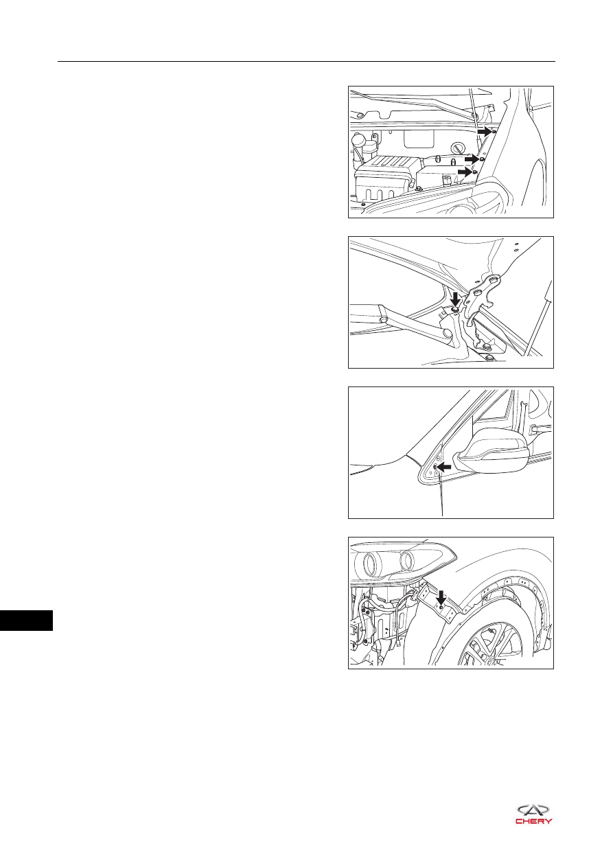
9. Remove the left fender assembly.

a. Remove 3 fixing bolts (arrow) between the upper part 

of fender assembly and body.

(Tightening torque: 10 ± 1 N·m)

b. Remove the fixing bolt (arrow) between fender 

assembly and engine hood hinge.

(Tightening torque: 10 ± 1 N·m)

c. Remove the fixing bolt (arrow) between fender 

assembly and body.

(Tightening torque: 10 ± 1 N·m)

d. Remove the fixing bolt (arrow) between front part of 

fender assembly and body.

(Tightening torque: 10 ± 1 N·m)

RT21480240

RT21480250

RT21480260

RT21480270

48–

27

48

e. Remove 2 fixing bolts (arrow) between inner part of 

fender assembly and body.

(Tightening torque: 10 ± 1 N·m)

f. Remove the fixing bolt (arrow) between lower part of 

fender assembly and body.

(Tightening torque: 10 ± 1 N·m)

g. Remove the clip from the front windshield lower 

garnish weatherstrip, and remove the left fender 
assembly.

10.Remove the left fender sponge.

RT21480280

RT21480290

RT21480241

RT21480300

48–

28

48

Installation

Installation is in the reverse order of removal.

CAUTION

 Be sure to wear safety equipment to prevent accidents when installing front fender.
 Try to prevent body paint surface from being scratched when installing front fender.
 Make sure that front fender is installed correctly and fitting clearance between front fender and body is 

appropriate when installing front fender.

48–

29

48

Engine Lower Protector Assembly

Removal

HINT:

 Use the same procedures for the right side and left side.

 Procedures listed below are for the left side.

1. Remove the engine lower left protector assembly.

a. Remove 4 fixing bolts (arrow) from the engine lower 

left protector assembly.

(Tightening torque: 10 ± 1 N·m)

b. Remove the fixing screw (1) from the engine lower left 

protector assembly.

(Tightening torque: 3 ± 1 N·m)

c. Remove 2 plastic clips (arrow) from the engine lower 

left protector assembly, and remove the left engine 
lower left protector assembly.

Installation

Installation is in the reverse order of removal.

CAUTION

 Be sure to wear safety equipment to prevent accidents when removing engine lower protector assembly.
 Try to prevent body paint surface from being scratched when removing engine lower protector assembly.

1

RT21480340

RT21480350

CAUTION

 Be sure to wear safety equipment to prevent accidents when installing engine lower protector assembly.
 Try to prevent body paint surface from being scratched when installing engine lower protector assembly.


Content   ..  515  516  517  518   ..