Chery Tiggo 5 (T21). Service manual - part 483
 

  Index      Chery     Chery Tiggo 5 (T21) - service and repair manual 2014 year


Search            copyright infringement  


Content   ..  481  482  483  484   ..


Chery Tiggo 5 (T21). Service manual - part 483


45–

10

45

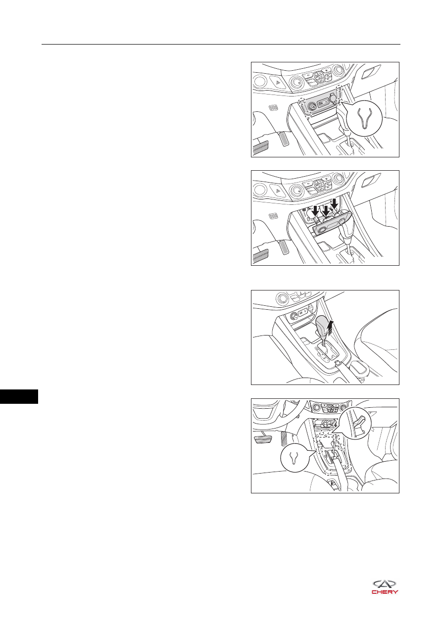
5. Remove the USB panel assembly.

a. Using a screwdriver wrapped with protective tape, pry 

up the clips on USB panel assembly.

b. Disconnect the connectors (arrow) from USB panel 

assembly, and remove the USB panel assembly.

6. Remove the gearshift cover plate assembly (for CVT model).

a. Pull out the shift knob in the direction of arrow as 

shown in the illustration.

b. Using a screwdriver wrapped with protective tape, pry 

up the clips on gearshift cover plate assembly.

AUX

iPod

POWER

OUTLET

12V   120W

A/C

OFF

RT21450060

A/C

OFF

RT21450070

R

S

RT21450080

S

P

R

N

MD

OFF

ON

A/C

RT21450090

45–

11

45

c. Disconnect the connectors (arrow) from gearshift 

cover plate assembly, and remove the gearshift cover 
plate assembly.

7. Remove the gearshift cover plate assembly (for MT model).

a. Using a screwdriver wrapped with protective tape, pry 

up the clips on gearshift cover plate assembly.

b. Pull out the gearshift cover plate assembly in the 

direction of arrow as shown in the illustration.

8. Remove the auxiliary fascia console front left protector (take left side as an example).

a. Remove the fixing bolt (arrow) from auxiliary fascia 

console front left protector.

(Tightening torque: 5 ± 1 N·m)

b. Using a screwdriver wrapped with protective tape, pry 

up the claws on auxiliary fascia console front left 
protector, and remove the auxiliary fascia console 
front left protector.

9. Remove the auxiliary fascia console assembly.

a. Remove the fixing screw (arrow) from the side of 

auxiliary fascia console assembly (take left side as an 
example).

(Tightening torque: 1.5 ± 0.5 N·m)

b. Remove the fixing bolt (1) from the side of auxiliary 

fascia console assembly (take left side as an 
example).

(Tightening torque: 5 ± 1 N·m)

S

P

R

N

MD

OFF

ON

A/C

RT21450100

OFF

ON

A/C

RT21450110

RT21450130

1

RT21450140

45–

12

45

c. Remove 4 fixing screws (arrow) from front part of 

auxiliary fascia console assembly.

(Tightening torque: 1.5 ± 0.5 N·m)

d. Pull up the seat adjusting handle and move the front 

seat assembly to the foremost position.

e. Remove 2 fixing bolts (arrow) from rear part of 

auxiliary fascia console assembly.

(Tightening torque: 5 ± 1 N·m)

f. Using an interior crow plate, pry up the dowel pins on 

the front part of auxiliary fascia console.

OFF

A/C

RT21450150

RT21460071

RT21450170

OFF

A/C

RT21450180

45–

13

45

g. Disconnect the anti-theft coil connector (arrow).

h. Remove 4 fixing screws (arrow) from front storage 

box.

(Tightening torque: 1.5 ± 0.5 N·m)

i. Remove the auxiliary fascia console assembly.

Disassembly

1. Remove the anti-theft coil (for CVT model).

a. Disengage the claws (arrow), and remove the anti-theft 

coil.

2. Remove the auxiliary fascia console rear cover plate assembly.

a. Remove the fixing screw from auxiliary fascia console 

rear cover plate assembly.

(Tightening torque: 1.5 ± 0.5 N·m)

RT21450181

RT21450190

RT21450191

RT21450211


Content   ..  481  482  483  484   ..