Chery Tiggo 5 (T21). Service manual - part 429
 

  Index      Chery     Chery Tiggo 5 (T21) - service and repair manual 2014 year


Search            copyright infringement  


Content   ..  427  428  429  430   ..


Chery Tiggo 5 (T21). Service manual - part 429


37–

56

37

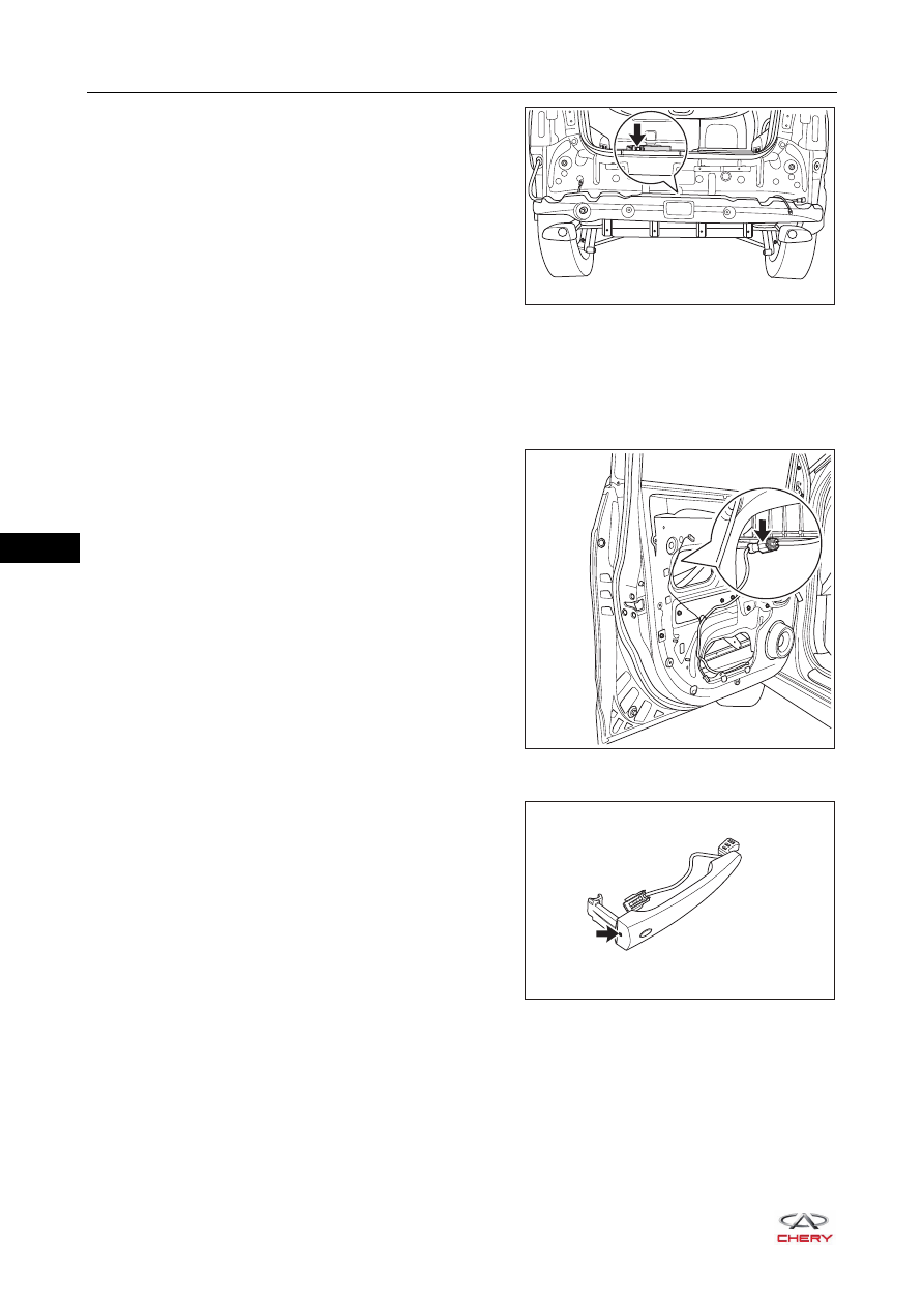
a. Disconnect the connector (arrow) from back door 

opener low frequency antenna. 

b. Using a screwdriver wrapped with protective tape, pry 

up the clip on back door opener low frequency 
antenna, and remove the back door opener low 
frequency antenna.

10.Remove the front left door protector assembly (

See page 47-23

).

11.Remove the front left door assist grip mounting bracket assembly (

See page 47-29

).

12.Remove the front left door protective film assembly (

See page 47-30

).

13.Remove the front left door key cylinder protective cover (

See page 37-44

).

14.Remove the front left door outside handle (

See page 47-31

).

HINT:
Front door handle sensor connector has been 
disconnected when removing the front door outside 
handle.

15.Remove the front left door handle sensor (built into low frequency antenna) (take left side as an example).

a. Remove the fixing crew (arrow) from front door 

outside handle.

(Tightening torque: 1.5 N·m)

RT21370500

RT21470390

RT21370450

37–

57

37

b. Using a screwdriver wrapped with protective tape, pry 

up the claws on front door outside handle.

c. Separate the front door handle sensor (1) and front 

door outside handle (2).

Installation

Installation is in the reverse order of removal.

RT21370451

RT21370460

1

2

CAUTION

 Clip on low frequency antenna and antenna mounting bracket should be fitted properly when installing 

low frequency antenna.

 Check if functions are normal after installing low frequency antenna.

37–

58

37

Wireless Key

Removal

1. Remove the wireless key (w/ passive entry & passive start).

a. Remove the mechanical key billet in the direction of 

arrow as shown in the illustration.

b. Using a screwdriver wrapped with protective tape, pry 

out the wireless key cover.

c. Separate the wireless key cover (1) and chip (2).

CAUTION

 DO NOT push the terminals with your hands when removing wireless key cover.
 Install battery positive and negative correctly when removing wireless key cover.
 DO NOT pry up the battery forcibly when removing wireless key cover, otherwise the terminals may be 

damaged.

 DO NOT touch the battery with wet hands when removing wireless key cover, otherwise the water may 

cause rust.

 DO NOT touch or move any components inside the transmitter when removing wireless key cover. 

Failure to do so may interfere with proper operation.

RT21370310

RT21370320

RT21370330

2

1

37–

59

37

d. Detach the claws (arrow) on battery holder, and 

remove the battery holder in the direction of arrow.

e. Take out the battery in the direction of arrow as shown 

in the illustration.

2. Remove the wireless key (w/o passive entry & passive start).

a. Using a screwdriver wrapped with protective tape, pry 

out the wireless key cover.

b. Take out the wireless key battery in the direction of 

arrow as shown in the illustration.

RT21370340

RT21370350

RT21370360

RT21370370


Content   ..  427  428  429  430   ..