Chery Tiggo 5 (T21). Service manual - part 403
 

  Index      Chery     Chery Tiggo 5 (T21) - service and repair manual 2014 year


Search            copyright infringement  


Content   ..  401  402  403  404   ..


Chery Tiggo 5 (T21). Service manual - part 403


35–

87

35

Luggage Compartment Light Assembly

Removal

1. Turn off all the electrical equipment and ignition switch.
2. Disconnect the negative battery cable.
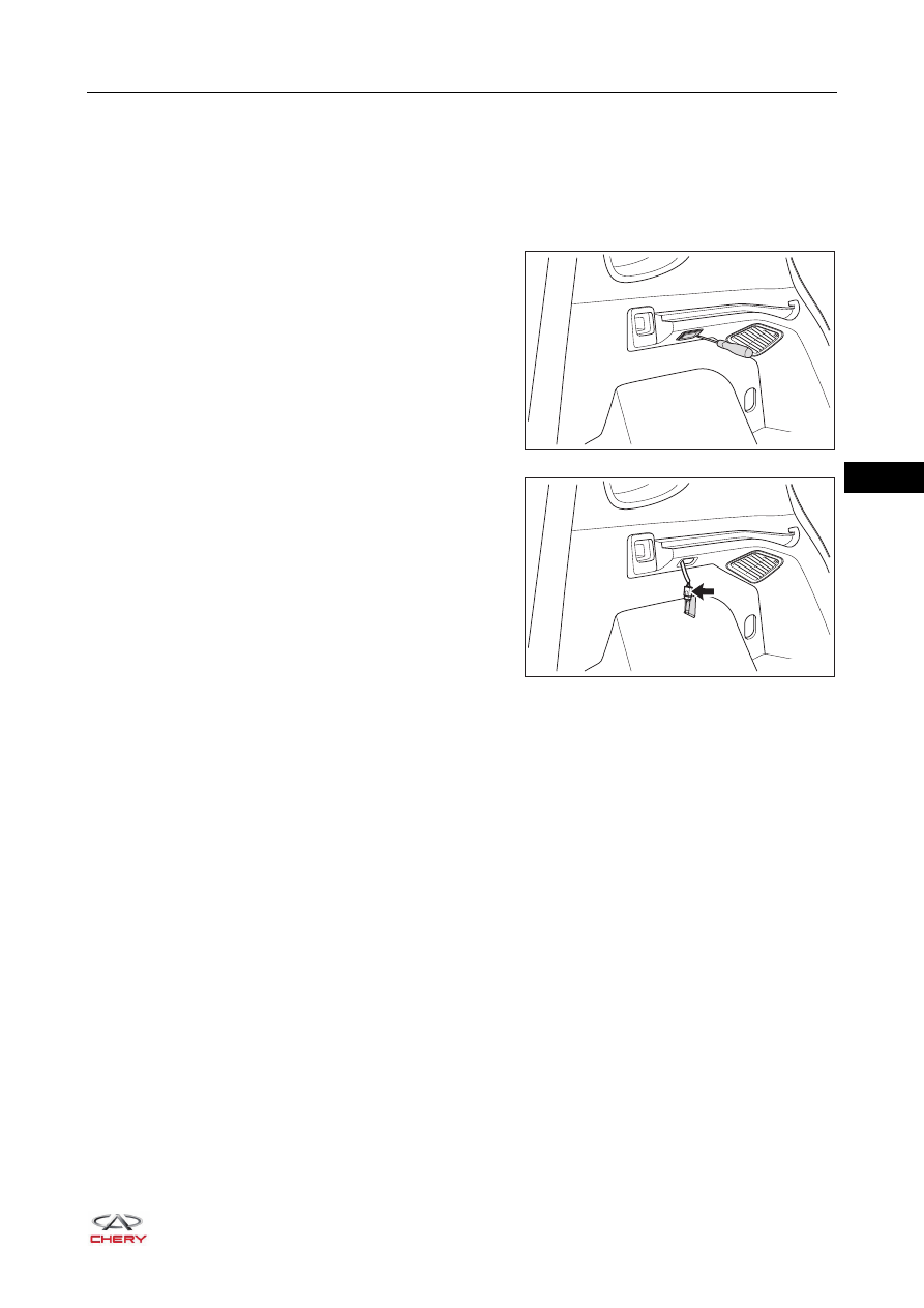
3. Remove the luggage compartment light assembly.

a. Using a flat tip screwdriver wrapped with protective 

tape, pry out the luggage compartment light assembly 
cover (right side).

b. Disconnect the luggage compartment light assembly 

wire harness connector (arrow).

c. Remove the luggage compartment light assembly.

Installation

Installation is in the reverse order of removal.

RT21490162

RT21490163

35–

88

35

Back-up Light Switch Assembly

Removal

1. Remove the back-up light switch assembly.

a. Stop the vehicle on a lifter, and support it with the lifter.
b. Turn off all the electrical equipment and ignition switch.
c. Disconnect the negative battery cable.
d. Raise the vehicle with the lifter.

e. Disconnect the back-up light switch assembly wire harness connector (arrow).
f. Remove the back-up light switch assembly (1).

HINT:
Transmission oil may flow out when removing back-up light switch assembly. Use a container to collect the 
oil.

Inspection

1. Check back-up light switch assembly.

a. Using ohm band of digital multimeter, check for 

continuity between terminals of back-up light switch 
assembly as shown in the table.

WARNING

 Bear sure to wear necessary safety equipments to avoid accidents.
 Check if safety lock of lifter is locked when performing vehicle lift repair and inspection.

1

RT21350400

ENVIRONMENTAL PROTECTION

 Drained transmission oil should be collected with a recovering tool.

-

+

1

2

RT21350410

Multimeter 

Connection

Switch Position

Specified 

Condition

Terminal 1 -

Terminal 2

Switch pushed

Continuity

Terminal 1 -

Terminal 2

Switch released

No continuity

35–

89

35

Installation

1. Apply thread locker to the threads of back-up light, and clean the transmission oil on the area between 

transmission and back-up light switch assembly before installing the back-up light switch assembly. Then 
install and tighten the back-up light switch.

(Tightening torque: 20 ± 2 N·m)

2. Check if the transmission oil level is in the proper position after installation.

a. It is not necessary to do anything, if it is in the proper position.
b. It is necessary to fill transmission oil to the specified position, if it is not in the proper position (fill the oil 

until it flows out of retaining plug).

35–

90

35

Hazard Warning Light Switch

Removal

1. Turn off all the electrical equipment and ignition switch.
2. Disconnect the negative battery cable.
3. Remove the combination switch cover (

See page 28-13

).

4. Remove the hazard warning light switch.

a. Disconnect the hazard warning light switch wire 

harness connector (arrow).

b. Press the claws (arrow) on both ends of the hazard 

warning light switch by hand, and push outward 
forcefully to remove it.

Inspection

1. Check hazard warning light switch.

a. Using ohm band of digital multimeter, check for 

continuity between terminals of hazard warning light 
switch as shown in the table.

If result is not as specified, replace hazard warning light 
switch.

A/C

RT21350420

A/C

RT21350430

1
2
3

4
5
6

-

+

RT21350440

Multimeter 

Connection

Switch 

Condition

Specified 

Condition

Terminal 1 -

Terminal 2

Switch pushed

Continuity

Terminal 1 -

Terminal 2

Switch released

No continuity


Content   ..  401  402  403  404   ..