Chery Tiggo 5 (T21). Service manual - part 367
32–
59
32
Self-diagnosis Detection Logic
HINT:
When performing electrical diagnosis and test, always refer to the relevant circuit diagram for the special
circuit and component information.
Diagnosis Procedure
a. Using a digital multimeter, check the battery voltage.
Standard voltage: 11 to 14 V
Use circuit diagram as a guide to perform the following procedures:
a. Turn ignition switch to LOCK, disconnect the negative battery cable and wait for at least 90 seconds.
b. Disconnect the SRS control module assembly connector I-046/B-072 and instrument panel fuse and relay
box wire harness connector I-007.
c. Disconnect the body wire harness connector B-055 and instrument panel wire harness connector I-036
(*2).
d. Check if wire harnesses are worn, pierced, pinched or partially broken.
e. Check for broken, bent, protruded or corroded terminals.
f. Check if related connector terminal contact pins are in good condition.
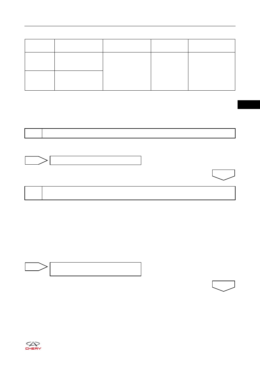
DTC Code
DTC Definition
DTC Detection
Condition
Warning Light
Condition
Possible Cause
B1250-16
Battery Voltage Circuit
Voltage Below
Threshold
Ignition switch ON
ON
Battery
Charging system
Wire harness and
connector
SRS control
module assembly
B1250-17
Battery Voltage Circuit
Voltage Above
Threshold
1
Check battery
Check charging system (
)
NG
2
Check wire harness and connector (SRS control module assembly - instrument panel fuse
and relay box)
OK
Repair or replace instrument panel wire
harness and connector
NG
OK