Chery Tiggo 5 (T21). Service manual - part 333
 

  Index      Chery     Chery Tiggo 5 (T21) - service and repair manual 2014 year


Search            copyright infringement  


Content   ..  331  332  333  334   ..


Chery Tiggo 5 (T21). Service manual - part 333


31–

36

31

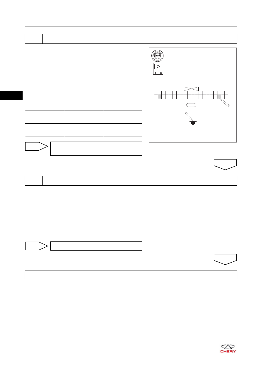
a. Turn ignition switch to LOCK.
b. Disconnect the negative battery cable.
c. Disconnect the HVAC control panel assembly connector 

K-012.

d. Using a digital multimeter, check for continuity between 

connector K-012 and body ground to check if system is 
short to ground according to the table below.
Standard Condition

a. Reconnect all disconnected connectors securely.
b. Connect the negative battery cable.
c. Turn ignition switch ON.
d. Use X-431 3G diagnostic tester (the latest software) to record and clear DTCs stored in the HVAC control 

panel assembly. 

e. Turn ignition switch to LOCK and wait for a few seconds.
f. Turn ignition switch ON.
g. Use X-431 3G diagnostic tester to read DTCs stored in the HVAC control panel assembly again.

4

Check wire harness and connector (HVAC control panel assembly - body ground)

RT21311110

-

+

K-012

1 2 3 4 5 6 7 8 9 10 11 12 13 14 15 16 17 18 19 20

21 22 23 24 25 26 27 28 29 30 31 32 33 34 35 36 37 38 39 40

Multimeter 

Connection

Condition

Specified 

Condition

K-012 (38) - Body 

ground

Always

No continuity

K-012 (22) - Body 

ground

Always

No continuity

Repair or replace A/C wire harness and 
connector

NG

5

Reconfirm DTCs

OK

Replace HVAC control panel assembly 

NG

System operates normally

OK

31–

37

31

AIR CONDITIONING 

DTC

B2127

AC Evaporator Temperature Sensor Short to Ground or 
Open 

ET21310110

HVAC 
CONTROL 
PANEL

K-012

BATTERY

RF10

7.5A

RF21

10A

IGNITION SWITCH
   ON OR START

10

21

1

2

3

4

5

6

7

8

9 10 11 12

13

85

85

87

87 30

87 30

30

86

86

85

86

14 15 16 17 18 19 20 21 22 23 24

25

27

26

1 2 3 4 5 6 7 8 9 10 11 12 13 14 15 16 17 18 19 20

21 22 23 24 25 26 27 28 29 30 31 32 33 34 35 36 37 38 39 40

W

K-012

22 21 20

18

19

17 16 15

13

14

12 11 10

8

9

7

6

5

3

4

2

1

B

I-039

B

I-007

2

WB

BR

4

21

WV

19

Y

INSTRUMENT 
PANEL FUSE 
AND RELAY 
BOX

I-007

I-039

K-007

4

B

BrW

8

I-039

K-007

I-037

W

K-007

1

2

3

4

5

6

8

9

10 11

13 14

15 16

18

17

21

20

22

7

12

19

LW

29

22

2

1

O

EVAPORATOR 
TEMPERATURE 
SENSOR

K-005

2

1

W

K-005

31–

38

31

Diagnosis Procedure

Use the circuit diagram as a guide to perform the following procedures:
a. Turn ignition switch to LOCK.
b. Disconnect the negative battery cable.
c. Disconnect the HVAC control panel assembly connector K-012 and evaporator temperature sensor 

connector K-005.

d. Check if wire harnesses are worn, pierced, pinched or partially broken.
e. Look for broken, bent, protruded or corroded terminals.
f. Check if related connector pins are in good condition.

a. Remove the evaporator temperature sensor.
b. Install the new evaporator temperature sensor to vehicle.
c. Use X-431 3G diagnostic tester to check if DTCs are still output.

DTC Code

DTC Definition

DTC Detection 

Condition

Possible Cause

B2127

AC Evaporator 
Temperature Sensor 
Short to Ground or 
Open 

Ignition switch ON

 Evaporator temperature sensor 
 Wire harness and connector 
 HVAC control panel 

CAUTION

 When performing electrical equipment diagnosis and test, always refer to the circuit diagram for related 

circuit and component information. 

1

Check wire harness and connector

Repair or replace A/C wire harness and 
connector

2

Check evaporator temperature sensor

Replace evaporator temperature sensor

NG

OK

NO

YES

31–

39

31

a. Turn ignition switch to LOCK.
b. Disconnect the negative battery cable.
c. Disconnect the HVAC control panel assembly connector 

K-012 and evaporator temperature sensor connector 

K-005.

d. Using a digital multimeter, check for continuity between 

terminals of connector K-012 and connector K-005 to 
check if there is an open in system according to the table 
below.
Standard Condition

a. Turn ignition switch to LOCK.
b. Disconnect the negative battery cable.
c. Disconnect the HVAC control panel assembly connector 

K-012.

d. Using a digital multimeter, check for continuity between 

connector K-012 and body ground to check if system is 
short to ground according to the table below.
Standard Condition

3

Check wire harness and connector (HVAC control panel assembly - evaporator temperature 
sensor)

RT21311120

-

+

K-012

1 2 3 4 5 6 7 8 9 10 11 12 13 14 15 16 17 18 19 20

21 22 23 24 25 26 27 28 29 30 31 32 33 34 35 36 37 38 39 40

K-005

2

1

Multimeter 

Connection

Condition

Specified 

Condition

K-012 (22) - 

K-005 (2)

Always

Continuity

K-012 (29) - 

K-005 (1)

Always

Continuity

Repair or replace A/C wire harness and 
connector

NG

4

Check wire harness and connector (HVAC control panel assembly - body ground)

OK

RT21311130

-

+

K-012

1 2 3 4 5 6 7 8 9 10 11 12 13 14 15 16 17 18 19 20

21 22 23 24 25 26 27 28 29 30 31 32 33 34 35 36 37 38 39 40

Multimeter 

Connection

Condition

Specified 

Condition

K-012 (22) - Body 

ground

Always

No continuity

K-012 (29) - Body 

ground

Always

No continuity

Repair or replace A/C wire harness and 
connector

NG

OK


Content   ..  331  332  333  334   ..