Chery Tiggo 5 (T21). Service manual - part 301
 

  Index      Chery     Chery Tiggo 5 (T21) - service and repair manual 2014 year


Search            copyright infringement  


Content   ..  299  300  301  302   ..


Chery Tiggo 5 (T21). Service manual - part 301


27–

8

27

ON-VEHICLE SERVICE

Adjustment

Abnormal parking brake operation may be caused by the worn brake shoe lining, incorrect brake shoe 
clearance adjustment, incorrect parking brake control mechanism stroke or incorrect parking brake 
component installation. Perform the following procedures to adjust the parking brake control mechanism 
stroke:
1. Support and raise the vehicle to a proper height.
2. Remove the rear wheel (

See page 24-9

).

3. Remove the rear brake disc (

See page 26-41

).

4. Remove the auxiliary fascia console assembly (

See page 45-9

).

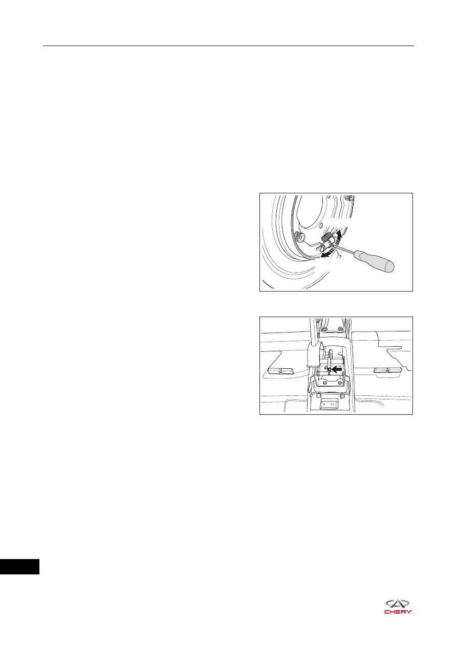
5. Adjust the parking brake shoe clearance:

a. Fully release the parking brake control mechanism.
b. Using a flat tip screwdriver, pry off the brake shoe 

adjusting hole plug, rotate the brake shoe clearance 
adjustment mechanism assembly to adjust parking 
brake shoe clearance, and attempt to rotate the rear 
brake disc by hand to confirm that brake disc rotates 
freely.

c. Check that there is no brake stuck for the brake shoe.

6. Adjust the parking brake control mechanism stroke:

a. Fully release the parking brake control mechanism.
b. Rotate the parking brake control mechanism 

adjustment nut, until the parking brake control 
mechanism stroke is correct.

c. Correct judging method: after adjustment, fully release parking brake control mechanism and rotate 

rear wheel by hand.
OK: Rear wheel can be rotated freely without dragging.
Pull up parking brake control mechanism until 1 clicking sound is heard. There is resistance when 
rotating rear wheel by hand. Pull up parking brake control mechanism until 5 to 6 clicking sounds are 
heard and the rear wheel cannot rotate.

d. When operating the parking brake control mechanism, check that brake warning light illuminates at the 

first click.
OK: Parking brake warning light always illuminates at the first click.

e. If result is not as specified, repeat above procedures until the parking brake control mechanism stroke 

is proper.

7. Install the auxiliary fascia console assembly (

See page 45-9

).

8. Install the rear brake disc (

See page 26-41

).

9. Install the rear wheel (

See page 24-9

).

(Tightening torque: 110 ± 10 N·m)

RT21270020

Shrink

Expansion

RT21270030

27–

9

27

Parking Brake Switch Assembly

On-vehicle Inspection

1. Disconnect parking brake switch assembly connector, 

and check the continuity of parking brake switch 
assembly with ohm band of digital multimeter as shown 
in the table below.
Standard Condition

If result is not as specified, replace parking brake switch 
assembly.

Removal

1. Fix the tire and wheel assembly.
2. Remove the auxiliary fascia console assembly (

See page 45-9

).

3. Remove the parking brake switch assembly.

a. Disconnect the parking brake switch assembly wire 

harness connector (arrow) as shown in the illustration.

RT21270040

1

-

+

Multimeter 

Connection

Condition

Specified 

Condition

Terminal 1 - Body 

ground

Parking brake 

applied (switch 

pin released)

Continuity

Parking brake 

released (switch 

pin pushed)

No continuity

CAUTION

 Be sure to wear necessary safety equipment to prevent accidents when repairing.
 Try to prevent body paint surface from being scratched during removal and installation.

RT21270050

27–

10

27

b. Using a cross screwdriver, loosen the fixing screw 

(arrow) of parking brake switch assembly.

c. Remove the parking brake switch assembly.

Inspection

1. Check parking brake switch assembly.

a. Check parking brake switch assembly for wear or break. Replace parking brake switch assembly as 

necessary.

b. Check if parking brake switch assembly compressed spring is damaged or weak elasticity. Replace 

parking brake switch assembly as necessary.

Installation

Installation is in the reverse order of removal.

RT21270060

27–

11

27

Parking Brake Control Mechanism Assembly

Removal

1. Fix the tire and wheel assembly.
2. Remove the auxiliary fascia console assembly (

See page 45-9

).

3. Remove the parking brake switch assembly (

See page 27-9

).

4. Remove the parking brake control mechanism assembly.

a. Fully release the parking brake control mechanism.
b. Loosen the locking nut (arrow) of parking brake 

control mechanism assembly to release the tension of 
parking brake cable assembly as shown in the 
illustration.

c. Remove 4 coupling bolts (arrow) between parking 

brake control mechanism assembly and body.

(Tightening torque: 23 ± 2 N·m)

d. Disengage the parking brake rear cable assembly 

from two grooves (arrow) on the rear of parking brake 
control mechanism assembly.

e. Remove the parking brake control mechanism assembly.

CAUTION

 Be sure to wear necessary safety equipment to prevent accidents when repairing.
 Try to prevent body paint surface from being scratched during removal and installation.

RT21270030

RT21270070

RT21270080


Content   ..  299  300  301  302   ..