Chery Tiggo 5 (T21). Service manual - part 273
 

  Index      Chery     Chery Tiggo 5 (T21) - service and repair manual 2014 year


Search            copyright infringement  


Content   ..  271  272  273  274   ..


Chery Tiggo 5 (T21). Service manual - part 273


25–

25

25

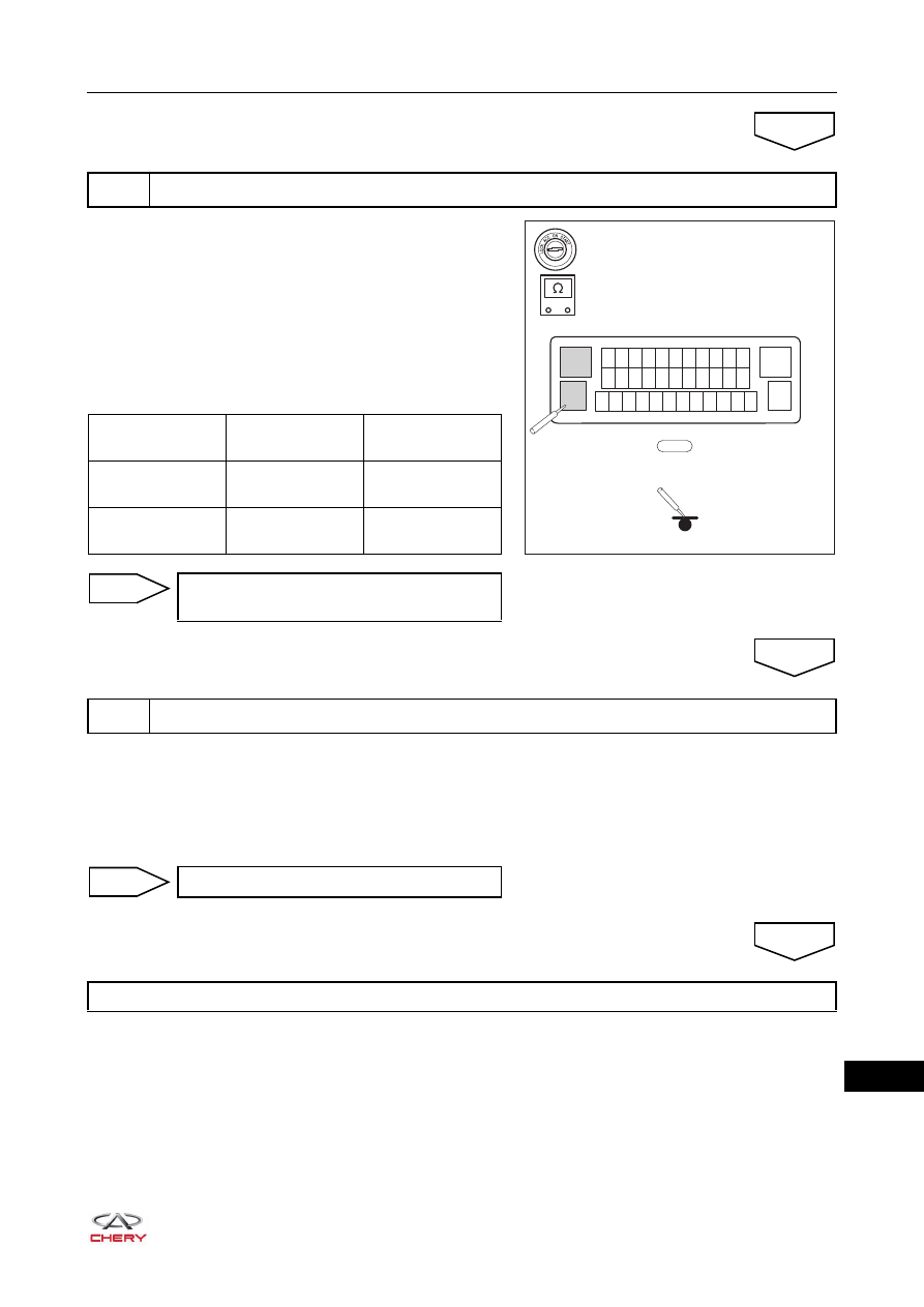
a. Turn ignition switch to LOCK.
b. Disconnect the negative battery cable.
c. Disconnect the ABS control module assembly connector 

E-085.

d. Using a digital multimeter, check for continuity between 

ABS control module assembly terminal 13, 38 and body 
ground to check if the system ground circuit is normal 
according to the table below.
Standard Condition

a. Use X-431 3G diagnostic tester to clear the DTC.
b. Start the engine.
c. Drive the vehicle at 15 km/h or more, read the ABS control module assembly DTC again with X-431 3G 

diagnostic tester.

d. Check if the same DTC is output.

5

Check wire harness and connector (ABS control module assembly - body ground)

OK

RT21250210

E-085

13

12 11 10 9 8 7 6 5 4 3 2

24 23 22 21 20 19 18 17 16 15 14

37 36 35 34 33 32 31 30 29 28 27 26

1

38

25

-

+

Multimeter 

Connection

Condition

Specified 

Condition

E-085 (13) - Body 

ground

Always

Continuity

E-085 (38) - Body 

ground

Always

Continuity

Repair or replace engine compartment 
wire harness and connector

NG

6

Reconfirm DTCs

OK

System operates normally

NO

Replace ABS control module assembly

YES

25–

26

25

DTC

C0020-04 ABS Pump Motor Control

ET21250050

BATTERY

ABS
CONTROL
MODULE

1

MF01

40A

R

13

12 11 10 9 8 7 6 5 4 3 2

24 23 22 21 20 19 18 17 16 15 14

37 36 35 34 33 32 31 30 29 28 27 26

1

38

25

B

E-085

E-085

38

13

Br

B

E-042

25–

27

25

Self-diagnosis Detection Logic

Diagnosis Procedure

a. Leave the vehicle for 5 minutes, clear and read the ABS control module assembly DTC again with X-431 

3G diagnostic tester.

b. Refer to DTC Confirmation Procedure.
c. Check if the same DTC is output.

DTC Code

DTC Definitions

DTC Detection 

Conditions

Possible Cause

C0020-04

ABS Pump Motor 
Control

These DTCs occur 
when any of the 
following conditions is 
met:
1. Pump motor 

operates with 
overload, and 
temperature is too 
high (over 
protection).

2. Return pump 

monitor still cannot 
detect the voltage 
signal after return 
pump motor relay 
operates for 60 ms. 

3. Return pump 

monitor detects the 
voltage for more 
than 2.5 s when 
return pump motor 
relay does not 
operate. 

4. Return pump 

monitor detects that 
the voltage does not 
drop when return 
pump motor relay 
stop operating. 

 Fuse malfunction
 Pump motor has poor ground 

connection

 System overheat protection
 Pump motor power supply is abnormal
 Pump motor relay malfunction.
 Pump motor malfunction

CAUTION

 When performing electrical equipment diagnosis and test, always refer to the circuit diagram for related 

circuit and component information.

1

Check for DTCs

Problem indicated by DTC is intermittent 
(system overheat protection)

NO

25–

28

25

a. Turn ignition switch to LOCK.
b. Disconnect the negative battery cable.
c. Remove the ABS fuse MF-01 (40 A) from the engine compartment fuse and relay box.
d. Check if the fuse is blown.

Use the circuit diagram as a guide to perform the following procedures:
 Turn ignition switch to LOCK.
 Disconnect the negative battery cable.
 Disconnect the ABS control module assembly connector E-085.
 Check if the wire harnesses are worn, pierced, pinched or partially broken.
 Look for broken, bent, protruded or corroded terminals.
 Check if related connector pins are in good condition.

a. Connect the negative battery cable.
b. Turn ignition switch to LOCK.
c. Disconnect the ABS control module assembly connector 

E-085.

d. Using a digital multimeter, measure the voltage between 

ABS control module assembly terminal 1 and body 
ground to check if the power supply circuit is normal 
according to the table below.
Standard Voltage

2

Check ABS fuse

YES

Replace ABS fuse

NG

3

Check wire harness and connector

OK

Repair or replace engine compartment 
wire harness and connector

NG

4

Check wire harness and connector (ABS control module assembly - battery)

OK

RT21250220

-

+

V

E-085

13

12 11 10 9 8 7 6 5 4 3 2

24 23 22 21 20 19 18 17 16 15 14

37 36 35 34 33 32 31 30 29 28 27 26

1

38

25

Multimeter 

Connection

Condition

Specified 

Condition

E-085 (1) - Body 

ground

Always

9 to 16 V

Repair or replace engine compartment 
wire harness and connector

NG


Content   ..  271  272  273  274   ..