Chery Tiggo 5 (T21). Service manual - part 137
 

  Index      Chery     Chery Tiggo 5 (T21) - service and repair manual 2014 year


Search            copyright infringement  


Content   ..  135  136  137  138   ..


Chery Tiggo 5 (T21). Service manual - part 137


09–

9

09

Activated Charcoal Canister Assembly

Removal

1. Turn off all the electrical equipment and ignition switch.
2. Disconnect the negative battery cable.
3. Raise the vehicle to the proper position.
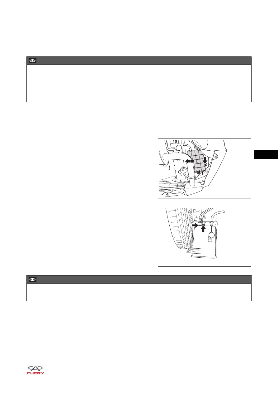
4. Remove the activated charcoal canister assembly.

a. Pull out the charcoal canister breather pipe (1) from 

body hole.

b. Remove the coupling bolt (arrow) between activated 

charcoal canister assembly and body

(Tightening torque: 7 ± 1 N·m)

c. Remove the activated charcoal canister assembly 

from body bracket in the direction of arrow as shown 
in the illustration.

d. Loosen the elastic clamps (arrow), disconnect the 

connection between hose and activated charcoal 
canister assembly, and remove the activated charcoal 
canister assembly.

e. Loosen the elastic clamp (1), remove the charcoal 

canister breather pipe from activated charcoal 
canister assembly.

CAUTION

 Be sure to wear necessary safety equipment when repairing to prevent accidents.
 Try to prevent body paint surface from being scratched during removal and installation.
 Before removal, mark fuel vapor pipe II, fuel vapor pipe I and charcoal canister breather pipe to avoid 

confusion.

RT21090060

1

RT21090070

1

CAUTION

 Positioning distance from hose end to elastic clamp is 3 - 5 mm.

09–

10

09

f. Remove the fixing nut (arrow), separate the activated 

charcoal canister assembly and activated charcoal 
canister protection box.

Installation

Installation is in the reverse order of removal.

RT21090080

ENVIRONMENTAL PROTECTION

 Unneeded activated charcoal canister assembly should be handled by the specialized department 

according to local laws and regulations. Never discard it at will.

09–

11

09

PCV Valve

Removal

1. Turn off all the electrical equipment and ignition switch.
2. Disconnect the negative battery cable.
3. Remove the engine trim cover assembly (

See page 10-10

).

4. Remove the PCV valve.

a. Take out the pipe assembly with PCV valve assembly 

from PCV valve rubber boot in the direction of arrow 
as shown in the illustration.

b. Remove the PCV valve (1) from line assembly.
c. Remove the PCV valve rubber boot (2) from T-joint.

Inspection

1. Install a clean hose to PCV valve.
2. Check PCV valve operation.

a. Blow air into the T-joint side, and check that air flows smoothly.

b. Blow air into intake manifold side, and check that air flows difficultly.
If result is not as specified, replace PCV valve.

3. Remove the clean hose from PCV valve.

CAUTION

 Be sure to wear necessary safety equipment when repairing to prevent accidents.
 Try to prevent body paint surface from being scratched during removal and installation.

RT21090090

1

2

RT21090100

WARNING

 DO NOT suck air through valve. Petroleum substances inside the valve are hazardous to your health.

09–

12

09

Installation

Installation is in the reverse order of removal.

CAUTION

 Press PCV valve rubber boot into T-joint, then press in the PCV valve.
 End surface of PCV valve larger diameter is flush with end surface of PCV valve rubber boot.


Content   ..  135  136  137  138   ..