Loader Bobcat 773. Service Manual - part 32
MAIN RELIEF VALVE
Checking
The tools listed will be needed to do the following
procedure:
MEL10003 – Hydraulic Tester
MEL10006 – Hydraulic Test Kit
Turn the key switch to the OFF position, as the engine
stops running, turn the key switch all the way to the left to
release the hydraulic pressure at the front auxiliary quick
couplers.
Lift and block the loader. (See Page 1–1.)
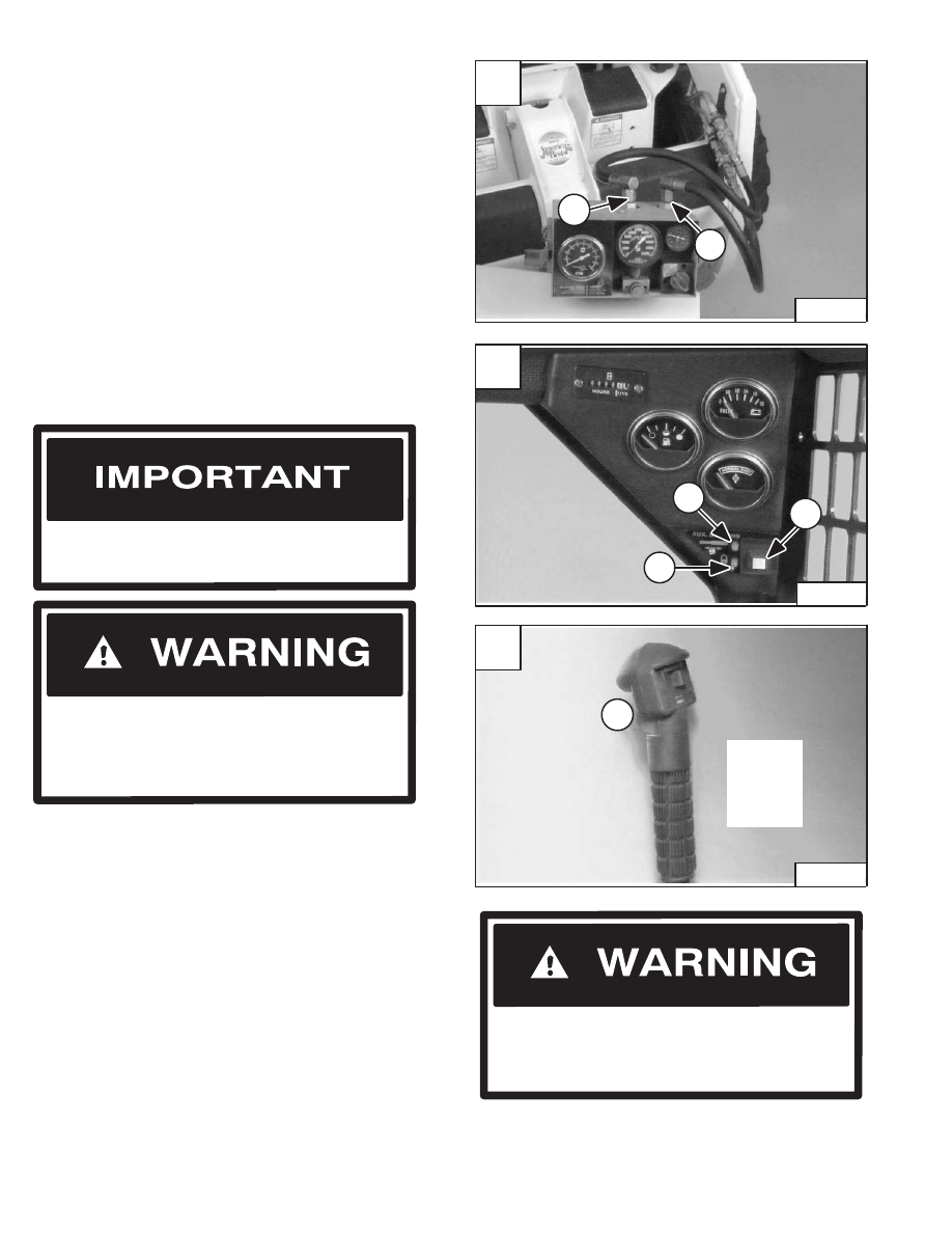
Connect the IN port (Item 1) [A] of the hydraulic tester to
the bottom (female) quick coupler on the loader.
Connect the OUT port (Item 2) [A] of the hydraulic tester
to the top (male) quick coupler on the loader.
The hydraulic tester must be in the fully open
position before you start the engine.
I–2024–0284
W–2017–0286
Put jackstands under the front axles and rear
corners of the frame before running the engine
for service. Failure to use jackstands can allow
the machine to fall or move and cause injury or
death.
Start the engine and run at low idle RPM. Push the mode
switch (Item 1) [B] twice (on the instrument panel) to
engage the front auxiliary hydraulics detent, the lights
(Items 2 & 3) [B] will come ON.
Push the button (Item 1) [C] for fluid flow to the quick
couplers.
Watch the flow meter on the hydraulic tester to make sure
the flow is correct. Increase the engine speed to full RPM.
There should be 15 GPM (56 L/min.) free flow. Turn the
restrictor control, on the tester, until the main relief valve
opens. The correct pressure for the main relief is 3000
PSI (20600 kPa).
Push the button (Item 1) [C] to disengage the detent
position to the front quick couplers.
If the relief valve pressure is not correct, stop the engine.
Adjust (See Page 2–75) or replace the main relief valve.
(See Page 2–62.)
Revised Jan. 99
A
P–04343
1
2
C
P–02152
1
Right
Steering
Lever
Control
(Optional)
W–2006–0284
When the engine is running during service, the
steering levers must be in neutral and the
parking brake engaged. Failure to do so can
cause injury or death.
–2–74–
773 BICS Loader
Service Manual
B
P–03272
2
1
3