Haima 7. Electrical System of Body. Instruction - part 2
 

  Index      Haima     Haima 7. Electrical System of Body. Instruction


Search            copyright infringement  


Content      ..      1      2      3      ..


Haima 7. Electrical System of Body. Instruction - part 2


Wiper and washer 

T-11 

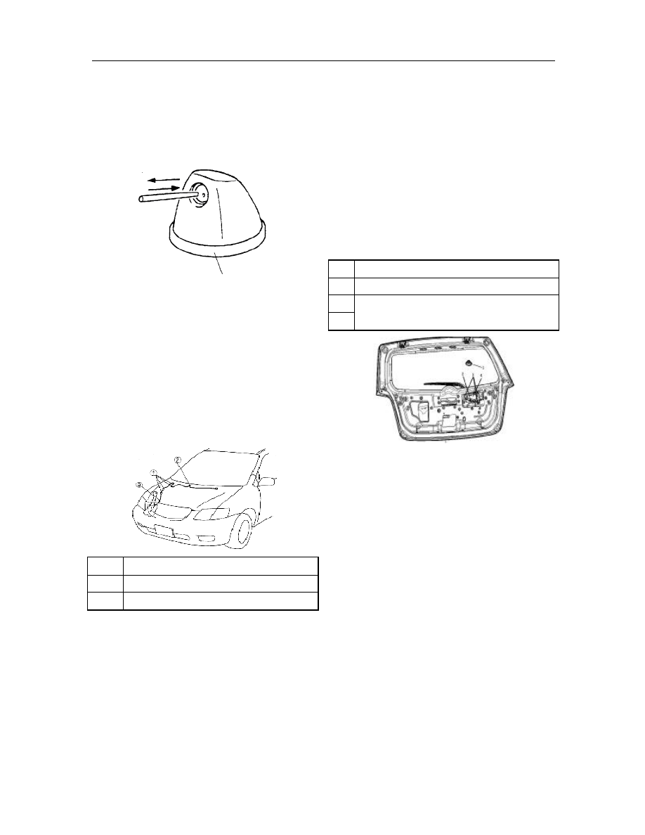
Cleaning of windshield washer nozzle   

Insert  an  needle  or  similar  tool  into  the  nozzle  of 
washer  and  clean  it  by  pulling  forward/backward. 
Remove  the  hose  from  the  nozzle  if  the  nozzle  still 
plugged after the cleaning. Assure there is sufficient 
cleaning  fluid and then turn on the washer switch to 
wash the interior of hose. 


Removal/installation  of  windshield  washer 
hose 

1. 

Remove engine bonnet acoustic baffle; 

2. 

Partly lift up the right fender; 

3. 

Remove as per the order indicated in the Table; 

4. 

The  installation  procedure  is  in  reverse  order 
with that of removal. 


1   

Snap   

2   

Connecting pipe   

3   

Windshield washer hose 


Removal/installation of rear wiper motor 

1.    Disconnect battery negative cable; 

2. 

Remove  rear  wiper  arm  and  blade  (See  the 
Removal  and  Installation  of  Rear  Wiper  Arm 
and Blade) 

3. 

Remove the inner trim panel of back door (See 
the  Removal  of  Inner  Trim  Panel  of  Back 
Door) 

4. 

Remove in the order as shown in Fig.   

5. 

Install in reverse order with that of removal.   

6. 

Adjust  rear  wiper  arm  and  blade.  (See 
Adjustment of rear wiper arm and blade) 

Outer sleeve 

Connector   

Bolt   

Rear wiper motor assembly   


Check of rear wiper motor   

1.    Disconnect battery negative cable; 

2.    Remove the inner trim panel of back door; 

3.    Remove the connector of rear wiper motor; 

4.    The  connector  B  of  rear  wiper  motor  is  in 

connection  with  the  positive  of  battery  and  A 
with  body  metal  part  for  the  purpose  of 
grounding; 

5.    Be  sure  that  the  rear  wiper  motor  is  properly 

operating; 

6    Release  the  grounding  wire  of  A  when 

operating on the rear wiper motor.   

7.    Confirm that the rear wiper parked on the Stop 

position. If not, replace the rear wiper motor. 

Washer nozzle 


-------------------------------------------------------------------------------------------------------------------------------------------------------------

Wiper and washer 

T-12 


Removal/installation  of  rear  wiper  arm 
and blade 

1.    Remove in the order as shown in Fig.; 

2.    Install in reverse order with that of removal; 

3.    Adjust  the  rear  wiper  arm  and  blade  (See  the 

Adjustment of Rear Wiper Arm and Blade) 


1   

Guard of rear wiper arm 

2   

Nut   

3   

Rear wiper arm 


Rear wiper blade 


Installation instructions of rear wiper arm 

1. 

Prior  to  the  installation,  clean  with  the  wire 
brush the arm coupling shaft of rear wiper. 


Adjustment of rear wiper arm and blade   

1.    Enable the rear wiper to  operate so  as  to  make 

the wiper to stop at the Stop position. 

2.    Align the wiper arm with the mark. 


Removal/installation of rear washer nozzle 

1.    Disconnect battery negative cable; 

2.    Remove the washer pipe plug; 

3.    Remove  the  connecting  hose  on  the  rear 

washer nozzle; 

4.    Press the lock latch on the rear washer; 

5.    Detach the rear washer nozzle; 

6. 

Install in reverse order with that of removal.   

7. 

Adjust the direction of rear washer nozzle (See 
the Adjustment of Rear Wiper Arm and Blade) 

Connector at element side 

(viewed from the terminal side 

Auto-Off 

Switch 

Mark 

-------------------------------------------------------------------------------------------------------------------------------------------------------------

Wiper and washer 

T-13 


Adjustment of rear washer nozzle   

Insert  a  needle  or  similar  tool  into  the  spray  orifice 
on the rear washer nozzle and adjust the direction of 
spray orifice. 


Removal/installation of rear washer hose 

1.    Disconnect battery negative cable; 

2.    Remove  necessary  trim  panel  above  the  right 

side wall; 

3.    Remove the washer hose from the clamp; 

4.    Partly  lift up the  right  fender  and  remove  the 

hose from the clamp; 

5.    Remove the hose from the washer tank; 

6.    Install in reverse order with that of removal. 


Lock latch 

Snap 

Washer hose 

Washer tank 

-------------------------------------------------------------------------------------------------------------------------------------------------------------

-------------------------------------------------------------------------------------------------------------------------------------------------------------

Alarm and Indication System


T-13 

Removal/installation 

of 

combination 

instrument 

1. 

Disconnect battery negative cable; 

2. 

Pull  down  the  adjusting  handle  of  tilting 
steering  wheel  and  press  down  the  steering 
wheel; 

3. 

Remove in the order indicated as in the Table; 

4. 

The  installation  procedure  is  in  reverse  order 
with that of removal;


Screw   

Barrel  and  combination  instrument 
guard 

Screw   

Connector   

Combination instrument 


Essentials  to  removal  of  combination 
instrument   

1. 

When  removing  the  combination  instrument, 
cover  the  steering  column  to  prevent  damage 
on the instrument.


Disassembly/assembly 

of 

combination 

instrument 

Attention: 

If the combination instrument comes  off or the PCB 
is  damaged,  the  system  will  be  unable  to  work 
properly  and  likely  to  cause  failure  or  abnormal 
operation. 

1. 

Disassemble  in  the  order  as  indicated  in  the 
Table; 

2. 

The  assembly  procedure  is  in  reverse  order  of 
that of disassembly;


Glass cover of combination instrument 

Upper cover of combination instrument 

Indicating pointer 

Combination instrument panel 

Zero-reset pole 

Lower cover of combination instrument 


Fabric 

-------------------------------------------------------------------------------------------------------------------------------------------------------------

Alarm and Indication System


T-14 

Check of combination instrument   

Speedometer   

Use of input/output inspection mode 

Set  the  speedometer  at  the  DTC  12  under  the 
input/output  inspection  mode  and  check  the 
speedometer.


Use of speed detector   

1. 

Adjust the tire pressure to the specified value; 

2. 

By  use  of  the  speed  detector,  confirm  the 
indication  of  speedometer  is  within  the  range 
of the following table:


Indication of 

speedometer (km/h) 

Allowed range (km/h) 

20 

18-22 

40 

36-44 

60 

54-66 

80 

72-88 

100 

90-110 

120 

108-132 

140 

126-154 

160 

144-176 

180 

162-198 

200 

180-220 

220 

198-242 

3. 

Verify  that  the  fluctuation  of  speedometer 
pointer remains within the allowed range. If the 
speedometer  pointer  doesn’t  move  or  the 
indication  is  beyond  the  allowed  range,  check 
the  ABS  hydraulic  unit/control  module  and 
relevant  harness.  If  the  ABS  hydraulic 
unit/control  module  and  relevant  harnesses  are 
normal, replace the combination instrument. 


The  tolerance  of  pointer  fluctuation  is  in  the 
scope of 3.0 km/h.


Tachometer   

Use of input/output inspection mode   

Set  the  tachometer  at  the  DTC13  under  the 
input/output  inspection  mode  and  check  the 
tachometer.


Use of static speed tester 

Attention: 

If  the  engine  speed  exceeded  the  allowed  scope,  it 
will  be  damaged, thus,  do  not  let  the  engine  speed 
be  higher  than  the  range  as  permitted  by  the 
tachometer 

indication 

when 

checking 

the 

tachometer. 

1. 

Connect  the  static  speed  tester  with  the 
IG-connector of DLC.


2. 

Verify  that  the  pointer  of  static  speed  tester 
remains  within  the  allowed  range  shown  as  in 
the  following  table.  If  the  pointer  of  static 
speed  tester  doesn’t  move  or  the  pointer 
exceeds  the  allowed  scope,  check  the  power 
system  control  module  of  engine  speed  signal 
transmitter  and  relevant  harness.  If  the  power 
system  control  module  of  engine  speed  signal 
transmitter  and  relevant  harness  are  in  normal 
state, replace the combination instrument.


Speed tester indication 

(rpm) 

Allowed scope (rpm) 

1000 

951-1077 

2000 

1976-2134 

3000 

3000-3190 

4000 

4024-4248 

5000 

5049-5305 

6000 

6073-6361 

7000 

7097-7418 

8000 

8121-8475 


Fuel gauge   

Set  the  fuel  gauge  at  the  DTC  23  under  the 
input/output  inspection  mode  and  check  the  fuel 
gauge.


DLC (data transmission connector) 

-------------------------------------------------------------------------------------------------------------------------------------------------------------

Wiper and washer 

T-15 

Water temperature gauge 

Set  the  water  temperature  gauge  at  the  DTC  24 
under  the  input/output  inspection  mode  and  check 
the water temperature gauge.


Repair of combination instrument 

Attention   

When  the  pointers  of  speedometer  and  engine 
tachometer will possibly jitter back and  forth  and  is 
unable  to  indicate  correctly  the  speed  or  revolution 
during the normal operation, please check as per the 
following procedures: 

1. 

Identify the failure.


2. 

Confirm  that  the  ROOM  fuse  has  been 
installed; 

3. 

Start  up  the  engine  and  let  the  engine  speed 
achieve  5,500rpm  or  until  the  pointer  does  not 
appear 

vibrated 

for 

long 

time 

(counterclockwise).


4. 

Lower  the  engine  speed  down  to  idle  and  set 
the ignition switch  on the  LOCK  position, and 
then  turn  the  ignition  switch  to  the  ON 
position. 

5. 

Confirm the pointer is reset to zero.


6. 

If the above procedures cannot reset the pointer 
to  zero, remove  the  gauge  cover  and  carefully 
calibrate the pointer with hand. 

7. 

Note that it is a normal instead of a  failure that 
the pointer vibrates when the battery is charged 
for the first time or the ROOM fuse replaced.


Check of fuel gauge sensor   

1. 

Remove fuel gauge sensor.   

2. 

Let  the  float  move  between  the  apogee  and 
perigee,  measure  with  an  ohmmeter  and 
confirm the resistance of fuel gauge sensor unit 
between the terminals A and B. 

3. 

Confirm  the  the  apogee  and  perigee  of  float 
position  as  shown  in  Fig.,  replace  the  fuel 
gauge  sensor  if  it  fails  to  meet  the  technique 
requirements.


Measuring 

point 

Red 

wire 

1/4 

1/2 

3/4 

Volume 

3L 

9L 

15L 

30L 

45L 

55L 

Resistance 

240±6 

215±6 

190±5 

140±4 

90±3 

40±2 

Pointing to zero   

Measure point 

Resistance 

Full 

Empty 

Full 


Empty 


-------------------------------------------------------------------------------------------------------------------------------------------------------------

Wiper and washer 

T-16 

Float 

position 
(height) 

23 

mm 

65.6 

mm 

104.5 

mm 

156.6 

mm 

197 

mm 

225.6 

mm 


Removal of water temperature sensor unit   

1. 

Remove the negative cable of battery; 

2. 

Disconnect the connection of connector; 

3. 

Remove the water temperature sensor.


Installation of water temperature sensor 

1. 

Apply  sealant  onto  surface  between  the  3

rd


screw thread and the top.


2. 

Install the water temperature sensor; 


Tightening torque:   
11.8-17.6N.m{120-180kgf.cm, 105-156in.lbf} 

3. 

Connect  the  connector  of  water  temperature 
sensor; 

4. 

Connect the negative cable of battery.


Check of water temperature sensor   

1. 

Remove water temperature sensor; 

2. 

Place the sensor into a water receptacle; 

3. 

Gradually heat water in the receptacle. 

4. 

Measure  with  an  ohmmeter  and  identify  the 
resistance  value  between  the  sensor  terminal 
and  sensor  housing  as  shown  in  the  following 
Table.  If  it  fails  to  meet  the  technique 
requirements,  replace  the  water  temperature 
sensor.


Water temperature 

Resistance 

49.8-50.2{121.7- 122.3} 

189.4-259.6 


In  terms  of  engine  TRITEC,  except  the  water 
temperature sensor, it  is also necessary to check the 
water  temperature  signal  from  the  ECU,  by 
methods shown specifically as below:   

1. 

Connect by use of an oscillograph, with the end 
of  signal  acquisition  connected  to  PIN  3E, the 
other end to body ground; 

2. 

Start  up  the  engine  and  observe  the  duty  cycle 
(active  low)  of  oscillograph  frequency.  It  runs 
properly if the following requirements are met:   

Engine water 

temperature 

(ºC) 

Pointer 

position of 

water 

temperature 

gauge 

Pointer error of 

water temperature 

gauge (angle of 

pointer travel) 

Duty cycle 

output of 
ECU (%) 

50 

Wire C 

0±2.5 

18±2 

85 ~ 105 

1/2 travel 

(A-B) 

63±2.5 

( 28 ~ 63)±2 

120 

Red alarm 

wire 

105±2.5 

78±2 

130 

Apogee of 

red zone 

126±2.5 

90±2 

Over 130 

Beyond the 

red zone 

126 ~ 134 

(over 92~98) 

If  the  relativity  between  the  duty  cycle  and  water 
temperature  is  correct,  but  the  indication  is  wrong, 
please verify firstly whether the pointer indicates the 
zero  (the  method  is  same  as  the  inspection  method 
of  tachometer).  If  the  zero  indication  is  correct,  it 
means  that  the  combination  instrument  is  damaged. 
Replace  the  combination  instrument.  If  the  correct 
indication  of  null  cannot  be  assured,  please  align 
first the pointer and recheck. If the problem persists, 
it  indicates  that  the  combination  instrument  is 
damaged. Replace the combination instrument. 

If  the  relativity  between  the  duty  cycle  and  water 
temperature  is  incorrect,  please  check  for  proper 
connection  of  harness.  If  the  connection  of  harness 
is correct, it  means that  there are problems in ECU, 
please  maintain  or  replace  ECU  by  referring  to  the 
part ECU- Power System Maintenance 


Joint 

Water  temperature 
sensor unit 

3

rd

 thread 

-------------------------------------------------------------------------------------------------------------------------------------------------------------

Wiper and washer 

T-17 

Check of oil pressure switch   

1. 

Confirm that the oil pressure warning light is lit 
when the ignition switch is in the ON position; 

2. 

Confirm  that  the  oil  pressure  warning  light 
goes  off  when  the  engine  starts.  If  the  oil 
pressure  warning  light  keeps  lit,  check  the  oil 
pressure  warning  light  and  relevant  harness.  If 
the  oil  pressure  warning  light  and  relevant 
harnesses are in normal condition, check the oil 
pressure.  If  the  oil  pressure  is  normal,  replace 
the oil pressure switch.


Removal/installation of horn 

1. 

Remove the negative cable of battery; 

2. 

Remove the front bumper; 

3. 

Disconnect the connection of horn connector; 

4. 

Remove the bolt; 

5. 

Remove the horn.


Tweeter   


Bolt 

Bodywork 

metal 

sheet 

Plug 

Horn 

-------------------------------------------------------------------------------------------------------------------------------------------------------------

Alarm and Indication System


T-18 

Low-tone horn   


6. 

The  installation  procedure  is  in  reverse  order 
with that of the removal. 


Removal/installation horn relay   

1.    Remove the negative cable of battery; 

2.    Remove the main fuse box cover; 

3.    Remove in the order as indicated in the Table; 

4.    The  installation  procedure  is  in  reverse  order 

with that of the removal. 


Horn relay   

Check of horn relay   

1. 

Remove horn relay.   

2. 

Check  with  an  ohmmeter  and  confirm  the 
continuity between the horn relay terminals.  If 
it  fails  to  meet  the  technique  requirements, 
replace the horn relay.


Input/output 

inspection 

mode 

of 

combination instrument 

Note:  Under  this  mode,  you  can  check  the  items 
listed in the table below. 


List of diagnostic trouble code (DTC):   

DTC  Check items 

Relevant items 

01 

Buckle  switch  of  safety 
belt 

Buckle switch 

04 

Door switch 

Lighting 

of 

ignition 

switch key   

Indoor light control 

Power door lock system 

Light warning buzzer   

05 

Door lock linkage switch 

Indoor light control 

Power door lock system 

06 

Outside 

door 

handle 

switch 

Timing 

function 

of 

ignition switch/door   

key lighting 

08 

TNS relay   

Light warning buzzer   

Lighting everywhere 

10 

Speed signal 

Speedometer   

11 

PCM   

Tachometer   

12 

Speedometer   

Speedometer   

13 

Tachometer   

Tachometer   

14 

Buzzer   

Light warning buzzer   

16 

Fuel level warning light   

Fuel level warning light   

18 

Lock  hole  lighting  of 
ignition switch 

Lock  hole  lighting  of 
ignition switch 

22 

Fuel gauge sensor unit 

Fuel gauge   

23 

Fuel gauge   

Fuel gauge   

24 

Water 

temperature 

sensor unit   

Water 

temperature 

gauge 

25 

Water temperature gauge 

Water 

temperature 

gauge 

26 

LCD   

LCD   

27 

Indoor light 

Indoor light control 

31 

Key reminder switch 

Key  reminder  warning 
buzzer   

Screw 

Bodywork metal 

sheet 

Plug 

Horn 

Main fuse box 

Continuity 

Terminal 

Step 

-------------------------------------------------------------------------------------------------------------------------------------------------------------

-------------------------------------------------------------------------------------------------------------------------------------------------------------

Alarm and Indication System


T-18 

Attention   

The  diagnostic  trouble  codes  not  incorporated  may 
be  possibly  displayed  but  unable  to  check.  The 
diagnostic  trouble  codes  are  displayed  in  numerical 
order.  When  performing  the  check,  stop  the 
inspection  mode  and  then  restart  the  check  if  the 
diagnostic trouble to be checked is smaller than that 
of actual check. 

When  the  diagnostic  trouble  code  is  not  DTC  10, 
the  inspection  of  input/output  mode  will  be 
cancelled, if  the  front  wheel has been  driven before 
the  speed  signal  is  inputted  into  the  combination 
instrument.  Hold  pressed  the  odometer/hodometer 
switch  for  1s  or  even  longer,  which  can  search  the 
diagnostic trouble code faster forward.


Operation procedure 


Start 

Remove the negative connection of battery 

Except 

DTC 22 

and 24 

Preparation 

DTC 22 and 24 

Disconnect the connectors of following parts and confirm the continuity of harness 
l  DTC22: Between the combination instrument and fuel gauge sensor   
l  DTC24: Between the combination instrument and water temperature sensor 
Is there any continuity between them? 
 

Connect the connector of 

combination instrument 

Yes 

No 

Repair the harness. If the system fault 

persists after the harness repaired, 

connect the connector of combination 

instrument 

Connect the special tool (fuel and water 

temperature gauges) with the combination 

instrument 

Open the driver-side door 

Remove the negative connection of battery 

Wait for more than 30s after the negative connection of battery removed and then connect the 

negative wire of battery. 

Operate as per the following order within 30s after the negative wire of battery connected.   
1. Turn the ignition switch to the ON position; 
2. Press 3 times the switch of driver-side door; 
3. Press 3 times the switches of odometer/hodometer 


Does the odometer /hodometer DTC 00 display? 

Yes 

No 

Press the odometer /hodometer switch to choose DTC. 

Check the parts as per “Check of Fault Diagnostic Code”, to see 

whether the system is normal or not? 

No 

Yes 

There is any DTC to be checked? 

Yes 

No 

Repair or replace the fault part. 

Turn the ignition switch to the LOCK position. 

Remove the negative connection of battery 

Disconnect the connection with the special tool (fuel and water temperature gauge testing instrument). If 

necessary, connect the connectors of fuel gauge sensor assembly and temperature sensor. 

Connect the negative wire of battery 

End 

Check 

procedure 

Terminate the 

check mode 

procedure of 
combination 

instrument 

input/output 

-------------------------------------------------------------------------------------------------------------------------------------------------------------

Alarm and Indication System


T-19 

Check sequence 

Attention: When checking  more than two DTCs, the check shall be  operated  as  per the priority  listed in the 
following table: 

Check priority 

Position of ignition 

switch 

Check of code 

ON 

22, 24 

01,  04,  05,  07,  08,  09,  10,  11,  12,  13,  14,  15,  16,  17,  18, 
20 ,21, 23, 25, 26, 27, 29, 40, 41, 42 

LOCK 

31 

Check of diagnostic trouble code   

DTC 01 

Buckle switch Signal On/Off 

Combination instrument connectors 


Harness side connector 

(Viewed from the harness side) 

XMET18W016 

Diagnostic program 

Steps 

Check 

Display 

Measures 

Unfasten  the  driver-side 
safety 

belt 

(buckle 

switch On) 


Go to the next step. 


Measure 

the 

voltage 

of 

combination 

instrument terminal 1P 

Is the voltage equal to 0V? 
l  If  this  value  is  satisfied,  replace  the 

combination instrument; 

l  If  this  value  is  unsatisfied,  check  the 

following parts. 
—  Buckle switch   
—  Harness 

(buckle 

switch 

Combination instrument) 

Fasten  the  driver-side 
safety belt 

(Buckle switch Off) 


Measure 

the 

voltage 

of 

combination 

instrument terminal 1P. 

Is the voltage equal to B+? 
l  If  this  value  is  satisfied,  replace  the 

combination instrument. 

l  If  this  value  is  unsatisfied,  check  the 

following parts. 
—  Buckle switch   
—  Harness(buckle switch - combination 

instrument) 


Is  the  signal  input  of  combination  instrument 
normal? 


-------------------------------------------------------------------------------------------------------------------------------------------------------------

Alarm and Indication System   

T-20 

DTC 04 

Door switch Signal On/Off 

Combination instrument connectors 


Harness side connector   

(Viewed from the harness side) 

XMET18W018


Diagnostic program   

Steps 

Check 

Display 

Measures 

Open  the  driver-side 
door 

(Door switch On) 


Close  the  driver-side  door  and  then  go  to  the  next 
step. 


Measure  the  voltage  of  combination  instrument 
terminal 1I. 

Is the voltage equal to 0V? 
l  If this value is satisfied, replace the combination 

instrument; 

l  If this  value  is  unsatisfied,  check the  following 

parts. 
—  Door switch 
—  Harness(Combination 

instrument—door 

switch) 

Open 

occupant-side 

doors.   

(Door switch On) 


Close  the  occupant-side  doors  and  then  go  to  the 
next step. 


Measure  the  voltage  of  combination  instrument 
terminal 1I. 

Is the voltage equal to 0V? 
l  If this value is satisfied, replace the combination 

instrument; 

l  If this  value  is  unsatisfied,  check the  following 

parts. 
—  Door switch 
—  Harness(combination 

instrument—door 

switch) 

Open  driver-side  rear 
door.  (Door  switch 
On) 


After closing the driver-side rear door, go to the next 
step. 


Measure  the  voltage  of  combination  instrument 
terminal 1I. 

Is the voltage equal to 0V? 
l  If this value is satisfied, replace the combination 

instrument.   

l  If this  value  is  unsatisfied,  check the  following 

parts.   
—  Door switch 
—  Harness  (combination  instrument—door 

switch) 

-------------------------------------------------------------------------------------------------------------------------------------------------------------

Wiper and washer 

T-21 

Steps 

Check 

Display 

Measures 

Open 

occupant-side 

rear door (Door switch 
On) 


After  closing  the  occupant-side  rear  door,  go  to  the 
next step. 


Measure  the  voltage  of  combination  instrument 
terminal 1L. 

Is the voltage equal to 0V? 
l  If this value is satisfied, replace the combination 

instrument.   

l  If this  value  is  unsatisfied,  check the  following 

parts. 
—  Door switch 
—  Harness(combination 

instrument—door 

switch) 

Open  lift  gate  (Trunk 
light switch On) 


Close the lift gate and then go to the next step. 


Measure  the  voltage  of  combination  instrument 
terminal 1I. 

Is the voltage equal to 0V? 
l  If this value is satisfied, replace the combination 

instrument; 

l  If this  value  is  unsatisfied,  check the  following 

parts. 
—  Door switch 
—  Harness(combination 

instrument—door 

switch) 

Close all doors and lift 
gate  (Door  and  trunk 
light switches Off) 


Measure  the  voltage  of  combination  instrument 
terminal 1L. 

Is the voltage equal to B+? 
l  If this value is satisfied, replace the combination 

instrument; 

l  If this  value  is  unsatisfied,  check the  following 

parts. 
—  Door switch 
—  Harness(combination 

instrument—door 

switch) 


The  signal  input  of  combination  instrument  is 
normal. 


DTC 05 

Switch signal On/Off of door lock linkage 

Combination instrument connectors 


Harness side connector   

(Viewed from the harness side) 

XMET18W017


-------------------------------------------------------------------------------------------------------------------------------------------------------------

Alarm and Indication System


T-22 

Diagnostic program 

Steps 

Check 

Display 

Measures 

Set 

the 

button 

of 

driver-side door lock to the 
Lock  position  (switch  of 
door  lock  linkage  in  the 
Off position ) 


Go to the next step. 


Measure  the  voltage  of  combination 
instrument terminal 3F. 

Is the voltage equal to 0V? 
l  If  this  value  is  satisfied,  replace  the 

combination instrument.   

l  If this  value is unsatisfied, Check the 

following parts.   
—    Door lock linkage switch 
—  Harness 

(combination 

instrument—  Door  lock  linkage 
switch) 

Set 

the 

button 

of 

driver-side door lock to the 
Unlock  position(Door  lock 
linkage  switch  in  Unlock 
position) 


Measure  the  voltage  of  combination 
instrument terminal 3F. 

Is the voltage equal to B+? 
l  If  this  value  is  satisfied,  replace  the 

combination instrument.   

l  If this  value is unsatisfied, Check the 

following parts.   
—  Door lock linkage switch 
—  Harness 

(Combination 

instrument-door 

lock 

linkage 

switch) 


The 

signal 

input 

of 

combination 

instrument is normal. 


DTC 07 

Rear windshield switch signal On/Off 

Combination instrument connectors 


Harness side connector   

(Viewed from the harness side) 

XMET18W017


-------------------------------------------------------------------------------------------------------------------------------------------------------------


Content      ..      1      2      3      ..