VT2-VT3 for Haima ZZ. Instruction - part 4
 

  Index      Instructions     VT2-VT3 for Haima ZZ. Instruction


Search            copyright infringement  


Content      ..     2      3      4      5     ..


VT2-VT3 for Haima ZZ. Instruction - part 4


文 件 

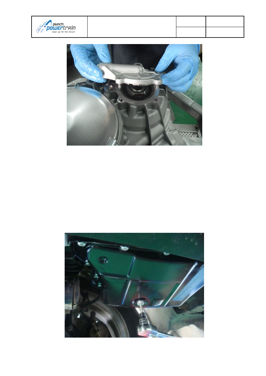
Fig.2:remove secondary cover 

2.6.2.9.  Replacing oil pan 

When: 
In case of oil pan damage and or leak. 
How: 
-Drain the oil by removing the oil drain plug (see Fig. 9-1) 
-Let all oil drip out, discard old drain plug 
-Remove oil pan by unscrewing all 13 screws from the oil pan (see Fig. 9-2) 
-Discard the oil pan gasket and oil pan 
-Take new oil pan and gasket 
-Fix oil pan with new gasket by tightening the screws according to Fig. 9-3 with 9.5Nm 
+/- 1Nm  
-Refill transmission according instruction (see 2.1). 


Fig. 9-1 Remove oil drain plug 


文 件 

Fig. 9-2 Removing the oil pan 


Fig. 9-3: Bolts sequence 

2.6.2.10.  Replacing oil filter 

 
When:  
Oil filter need to be replaced at least every 60000 km. This service interval can be 
advanced to match with the standard service of the vehicle.  
How: 
-Drain the oil by removing the oil drain plug (see Fig. 9-1) 
-Let all oil drip out, discard old drain plug 
-Refit new drain plug and tighten with 11Nm +/-1Nm 
-Remove oil pan by unscrewing all 13 screws from the oil pan (see Fig. 9-2) 


文 件 


Fig. 10-1: Lubricate the 0-ring 


Fig. 10-2: Fix oil filter in position 

2.6.2.11.  Replacing drive mode sensor 

When: 


文 件 


Fig. 11-1: Loosen drive mode sensor bolts 


文 件 

Fig. 11-2: Push sensor down to remove pin from metal slide 


Fig. 11-3: Unlock drive mode sensor connector 


文 件 

Fig. 11-4: Pin locked in dedicated space of the metal slide 

2.6.2.12.  Replacing hydraulic unit 

 
When: 
In case there is a problem with the transmission pressure or the driver feel shocks or 
abnormal driving behaviour, two main parts can cause this problem, hydraulic unit or 
oil pump. Also analyze the P-code and follow actions on specific P-code to replace 
either hydraulic unit or pump. In most of cases it is unclear which one the problem 
causes so one by one can be replaced and see if the problem is solved. 
How: 
-Follow steps to remove the drive mode sensor 
-Follow the sequence on Fig. 12-1 in reverse order 20-19-18-17-16-15-14-13-12-11-
10-9-8-7-6-5-4-3-2-1 to unscrew all hydraulic unit bolts 
-Take out the hydraulic unit and disconnect the 4 connectors. A small screwdriver can 
be used carefully to disconnect easier (see Fig. 12-2 and 12-3) 
-Take a new hydraulic unit and connect the 4 connectors. No mistake can be made 
due to the length of the cables 
-Place the hydraulic unit in place, there is a guiding pin on the back of the hydraulic 
unit that fits into a dedicated hole (see Fig. 12-4) 
-Make sure that the metal slide fits in the pin of the rooster cam plate (see Fig. 12-5) 
-Place the center screw and hand tighten it 
-Place the special alignment tool (480142) on the top left screw hole and screw it in 
(see Fig. 12-6) 
-Push the speed sensor cable behind the upper left corner of the hydraulic unit (see 
Fig. 12-6) 
-Place all screws of hydraulic unit, except the upper left one and tighten with 11Nm +/- 
1Nm in sequence 1-2-3-4-5-6-7-8-9-10-11-12-13-14-15-16-17-18-19-20 on Fig. 11-1 
When arriving at the upper left one, take out special tool and replace with screw and 
continue until screw 20. 
-Follow steps to place back the drive mode sensor 


文 件 

Fig. 12-1: Order of the bolts


Fig. 12-2: Use a screwdriver to separate the 4 connectors 

10 

11 

12 

13 

14 

15 

16 

17 

18 

19 

20 


文 件 

Fig. 12-3: Use a screwdriver to separate the 4 connectors 


Fig. 12-4: Guiding pin on the back of hydraulic unit 


文 件 

Fig. 12-5: Pin of rooster cam needs to fit in metal slide 


Fig. 12-6: Special alignment (480142) tool for hydr. unit 

2.6.2.13.  Replacing output speed sensor and bracket 

 
When

In case indicated by actions from the error code list 
How: 
-Follow steps to remove the hydraulic unit 
-Loosen bolt bracket output speedsensor and discard bolt (see Fig. 13-1) 
-Slide out the bracket, there is a dedicated sleeve in the selector shaft! (see Fig. 13-2) 
-Disconnect cable from speedsensor with long flat nose pliers (see Fig. 13-3) 
-Remove sensor from bracket by unscrewing bolt 
-Discard sensor and/or bracket 


文 件 

2Nm) 

-Connect wire and slide bracket back in the selector shaft 
-Take a new bolt bracket output speedsensor and tighten with 9.5Nm +/- 0.95Nm 
-Follow steps to place back the hydraulic unit 


Fig. 13-1: Loosen bolt bracket output speed sensor 


Fig. 13-2: Bracket output speed sensor 


文 件 

Fig. 13-3: Use long flat nose pliers to disconnect 

2.6.2.14.  Replacing primary speed sensor 

 
When

In case indicated by actions from the error code list 
How: 
-Follow steps to remove the primary cover 
-Loosen bolt of speedsensor and take out sensor (see Fig. 14-1) 
-Disconnect wire and discard sensor 
-Take new sensor and screw down with 8.5Nm +/- 2Nm 
-Connect wire to sensor 
-Follow steps to put back primary cover 


Fig. 14-1: Primary pully speed sensor 


文 件 

 
When: 
In case indicated by actions from the error code list 
How: 
-Follow steps to remove hydraulic unit 
-Disconnect output speed sensor 
-Disconnect the car cable harness connector from the main connector on the 
transmission 
-Remove the clip with pliers and push the main connector into the transmission (see 
Fig. 15-1, 15-2) 
-The drive mode sensor connector is clipped on the transmission, loosen that one first 
(see Fig. 15-3) 
-Remove the complete cable harness from the transmission and discard 
-Take new cable harness and put into transmission 
-The main connector has a sleeve which should fit over the securing key on Fig. 15-4, 
15-5 
-The use of a 45deg angled nose pliers can be helpful to fit in the main connector 
-Push clip back on main connector 
-Push drive mode sensor connector on the transmission (see Fig. 15-6) 
-Connect the output speed sensor 
-Follow steps to place back the hydraulic unit 


Fig. 15-1: Remove the clip from the main connector 


文 件 

Fig. 15-2: Push main connector into the transmission 


Fig. 15-3: Remove drive mode sensor connector from transmission 


文 件 

Fig. 15-4: Securing key 


Fig. 15-6: Push drive mode sensor connector on the transmission 

2.6.2.16.  Replacing the breather pipe 

 
When: 
In case of breather pipe damage which can cause dirt or water to enter the 
transmission. 
How: 
-Possibly the airbox, the battery and top bracket needs to be removed to have a clear 
access to the breather pipe. 
-Remove the clip on top of the breather pipe which connects it to the transmission 
housing. 
-Remove the breather pipe with pliers. Connect the pliers at the root (Aluminum piece 
of the breather pipe) and twist and pull to take it out. 


文 件 


-

Put the plastic clip (482253) around the pipe. 

-Put the pins of the plastic clip thru the hole of the metal clip (481456). 
-Push the metal clip firmly (till the end) onto the ridge of the transmission house. 
-Slide the breather cap (483117) complete over the top of the breather pipe. Fig. 16-3 
-Replace airbox and battery if needed. 


Fig. 16-1: Place the new breather pipe into the assembly tool 


Fig. 16-2: Hammer down the tool till the end with plastic hammer 


文 件 

Fig. 16-3: Place the clips and cap 


Content      ..     2      3      4      5     ..