Lotus Evora. Instruction - part 47
 

  Index      Lotus     Lotus Evora - service repair instruction 2009 year


Search            


Content   ..  45  46  47  48   ..


Lotus Evora. Instruction - part 47


Lotus Service Notes   


    Section JL

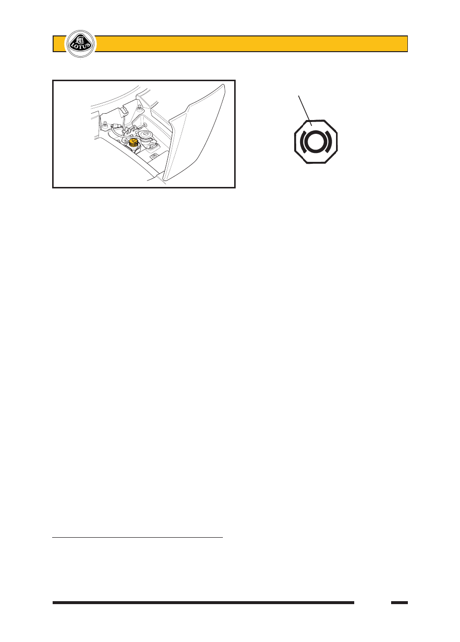
  As a bulb check, the tell tale should light for about 3 seconds when the ignition is first turned on, but may 

also be tested by pressing the button on the filler cap, which action should light the tell tale with the ignition 

switched on.

The reservoir is mounted on a bracket fixed to the wiper spindle support, and is connected to the master 

cylinder by flexible hoses.  An internal baffle divides the reservoir into two compartments, with one section sup-

plying the front brake circuit, and a second section supplying the rear brakes in addition to, via another flexible 

hose, the clutch master cylinder.  Service wear of the clutch friction plate will cause fluid to be displaced from 

the self adjusting clutch slave cylinder, back to the reservoir, and will counteract to some extent the dropping 

of the level due to brake pad wear.

If the reservoir needs topping up, first clean around the cap to reduce the possibility of contamination be-

fore unscrewing the cap;  it is not necessary to disconnect the level sensor cables.  Take suitable precautions 

to guard against damage to paintwork caused by brake fluid dripping from the level sensor.

Use only a fresh supply of DOT 4 non-mineral type fluid,identified by a yellow and black symbol.  Do NOT 

use DOT 5 silicone fluid, or any fluid which has been exposed to the atmosphere for more than a brief period, 

or any fluid suspected of being wet, dirty or contaminated.  Do not overfill.  Replace the filler cap securely.

Some service operations, such as replacing brake pads, will result in the displacement of fluid from the 

hydraulic circuit back into the reservoir.  In order to prevent fluid overflowing from the reservoir, it may be nec-

essary to remove some fluid using a syringe.

Renewal of Brake Fluid

Brake fluid absorbs water from the atmosphere over a period of time (i.e. is hygroscopic), resulting in a 

lowering of the boiling point of the fluid, and corrosion of the hydraulic system.  For optimum safety and brake 

performance, the brake fluid should be renewed every twelve months (including clutch release system).

Brake Bleeding Procedure

If the brake fluid is to be renewed, or an hydraulic component replaced, the system should be bled of air 

using the following procedure:

1.  Using conventional instruction techniques, or low air pressure applied to the reservoir, bleed the system from 

each calliper bleed nipple in turn until no air bubbles can be seen.

2.  Connect the Lotus Techcentre to the diagnostic link, select ABS and follow the brake bleeding instructions.  

Whilst this automatic process is taking place (with all 4 calliper nipples open), gently cycle the brake pedal 

up and down whilst keeping the reservoir topped up, to move any air bubbles displaced from the ABS unit 

down the hydraulic lines.  Finish by closing each nipple with the pedal down.

3.  Repeat step (1) to purge each calliper feed line in turn.

JL.4 - BRAKE PAD REPLACEMENT (front and rear)

Pad thickness may be checked with the wheel removed without disturbing the calliper.


Standard pad thickness (excluding backplate);  12.0 mm 

Minimum pad thickness (excluding backplate);  2.5 mm  

j146

Non-mineral type brake fluid symbol

(yellow & black)


BRAKE FLUID RESERVOIR                   

ohe21


Lotus Service Notes   


    Section JL

If the thickness of any pad is below the specified minimum, the axle set of pads should be renewed.   

1.  To remove the brake pads;  Use a pin punch to tap one of the pad retaining pins towards the inboard 

side.  Unhook and remove the anti-rattle spring plate, and tap out the second retaining pin.  Use pliers 

on the backplate lugs to withdraw the pads from the calliper, noting each pad's position if they are to be 

refitted.


Measure the lining thickness and renew the axle set of pads if any lining is below 2.5 mm.  

2.  Before replacing the pads, inspect the calliper for any signs of fluid leakage from a piston seal or joint, 

and replace the calliper if any such signs are evident.  Clean the pad recess in the calliper taking suitable 

precautions to protect from dust inhalation.  Inspect the brake disc surface condition and thickness (see 

below) and replace if necessary.

3.  If refitting the existing brake pads, refit in their original position.

4.  If fitting new pads, the pistons must be pushed back into the calliper using suitable calliper pliers, to provide 

the necessary space.  This action will return fluid to the master cylinder such that some fluid may need 

to be removed by syringe in order to prevent overflowing.  Do not lever between the disc and piston, or 

damage to both components may be caused.  Note that new pads are supplied with an anti-squeal overlay 

applied to the backplate, and the edge of the pad material should be marked 'FER 4212 FF'.

5.  Position the pads in the calliper, and insert the upper pad retaining pin from the inboard side.  Tap fully 

into position using a pin punch, and verify the security of the pin.  Renew the pin if in any doubt.

6.  Fit the anti-rattle spring plate into position with the top end tucked under the upper pin and the arrow point-

ing upwards on a front calliper, or downwards on a rear calliper.  Insert the second pin, pressing down the 

bottom of the spring plate so as to be captured by the lower pin.  Verify pin security.

7.  Before driving the car, press the brake pedal several times to bring the pads to their correct running po-

sition.  Top up the master cylinder reservoir (see above) if necessary, to bring the level to the top of the 

‘MAX’ mark.

-

0
564

Front Brake Shown

                                        Pad retaining pin

Brake disc

                                                  Brake pad


                                                      Anti-rattle 

                                                      spring plate

Calliper


j164b


Lotus Service Notes   


    Section JL

8.  Ensure the customer is made aware that maximum braking efficiency will be achieved if, for the first few 

hundred miles, needless heavy braking is avoided, and the brake pads are allowed to ‘bed in’ fully before 

being used to their full potential.

JL.5 - PARKING BRAKE MECHANISM

The parking brake ratchet lever is mounted between the seats in a fabricated steel structure which also 

houses the gearchange mechanism.  The lever activates a primary cable which exits the cabin at the front of 

the fuel tank bay, and turns through 90° to connect to an equalising yoke at the front of the engine bay.  The 

yoke forms the abutment for the primary outer cable, with the inner cable continuing through a slot in the yoke 

to link to the RH secondary cable.  The opposite end of the yoke connects to the LH secondary cable, with 

both secondaries penetrating the rear subframe and routing through the lower wishbone to their respective 

rear wheel parking brake backplates.  The interaction of the yoke with the three separate cables results in an 

automatically balanced force being applied to each of the secondary cables.

At the each brake backplate the secondary cable connects to a lever mechanism which provides a bal-

anced expanding force to the lower ends of the parking brake shoes which operate within brake drums formed 

integrally with the rear brake discs.  The upper ends of the shoes pivot against opposite ends of an adjustable 

length abutment, with access to the toothed adjuster screw available via a hole in the brake backplate.

The parking brake should be applied by pulling up the lever with high effort, and engaging the highest 

ratchet setting attainable.  When parking the car on a slope, the additional precaution should be taken of leav-

ing the transmission in first or reverse gear and steering the wheels towards the kerb.

Adjustment

At each service interval, the parking brake should be fully applied, and lever movement assessed by the 

number or ratchet 'clicks' attainable.  The adjustment is satisfactory when 4 or 5 clicks are achieved.

To make an adjustment;

1.  Ensure that the parking brake lever is fully off, and the adjuster in the LH secondary cable is fully slackened 

(shortened).  

2.  Remove both rear wheels.  Using the access hole in the brake drum and hub flange, turn the adjuster 

downwards to expand the shoes until the brake drum cannot be turned by hand.  Then back off the adjuster 

the minimum amount necessary to allow free rotation of the drum without rubbing, and then repeat for the 

opposite side.

              Parking brake lever

                      Primary cable


                                                    RH secondary cable

Micro-switch

                                            Equalising yoke

                                LH secondary cable


pl3305eg


Lotus Service Notes   


    Section JL

3.  The cable adjuster may then be tightened to remove slack until the 'click' specification is achieved.  Check 

that there is no brake drag with the lever fully off.

Parking Brake Shoes

Unless the parking brake shoes are mal-adjusted, the shoe material should suffer little wear.  To remove 

the shoes, remove the road wheel, fully slacken the brake shoe adjuster, and remove the brake disc (see below).   

Mark the shoes with their fitting position before  removing the steady pin and spring from each shoe by turning 

the pin 1/4 turn.  Allow the shoes to fold outboard and release from the adjuster.  Remove the upper retraction 

spring, and lever the shoes from the adjuster mechanism slots.

Refit in reverse order.

Parking Brake Lever

The parking brake lever is mounted in a steel bracket which also houses the gearchange lever.  The 

mounting bracket is bolted to an alloy support channel running down the centre of the cabin floor, to which it 

is secured by 12 setscrews.  The brake lever ratchet pawl operates a micro switch to light the ‘brakes’ tell tale 

lamp in the instrument panel whenever the ignition is switched on and the parking brake is applied.  The short 

front cable is connected to the lever assembly by a clevis pin with spring retaining clip.  When carrying out any 

work in this area, take care not to damage or misroute the electrical main harness.

The two secondary cables are routed through the lower wishbones and into the brake backplates where 

the cable nipples connect to the actuation levers by a 1/4 turn.

JL.6 - BRAKE DISCS

All four wheel brakes use a cast iron brake disc which is sandwiched between the wheel and its hub flange, 

being centralised by the hub spigot, and transmitting torque via the clamping force of the road wheel bolts.  A 

countersunk screw is used to retain the discs for convenience when servicing.  The 350 x 32 mm front discs 

and the 332 x 26 mm rear discs are all internally ventilated with directionally curved cooling vanes, and have 

cross-drilling to aid pad scouring available as an option.  The rear discs also incorporate a 185 mm inner drum 

to accommodate the parking brake function.

The condition of the brake disc friction surface is a major factor in brake performance and feel, with a good 

surface quality and minimal run-out and thickness variation being required.  After an extended lay up, some 

surface corrosion may develop on the discs which will cause a degradation in braking quality until the surfaces 

are cleaned up by normal brake action.  Excessive run-out or thickness variation as a result of overheating 

or extended wear, may cause brake judder and/or extended pedal travel due to pad ‘knock off’.  Scoring and 

ridging of the braking surfaces will be exacerbated by operation in dusty or unmetalled road environments, and 

will degrade braking performance.  

No skimming or re-surfacing of the brake discs is recommended.  If the disc becomes badly scored, or 

is out of specification in any way, it should be renewed.  NOTE: Ensure that there is no discernible free play 

in the wheel bearings before attempting to measure  brake disc run-out.  If disc run-out exceeds the service 

maximum, check the hub face run-out before replacing the disc.

Brake disc thickness

New          - front       32 mm 

            - rear        26 mm

Service minimum  - front       30 mm 

            - rear        24 mm

Runout               

New maximum              0.06 mm   

Service maximum            0.10 mm 

Hub

Disc mounting face run-out max.  0.05 mm 

Front Disc Replacement

1.  Remove the road wheel.


Content   ..  45  46  47  48   ..