Lotus Elise / Lotus Exige. Instruction - part 103
 

  Index      Lotus     Lotus Elise / Lotus Exige (engine 1ZZ/2ZZ) - service repair instruction 2004 year


Search            


Content   ..  101  102  103  104   ..


Lotus Elise / Lotus Exige. Instruction - part 103


Lotus Service Notes                                  Section QH

Page 2

GENERAL

 LA

YOUT

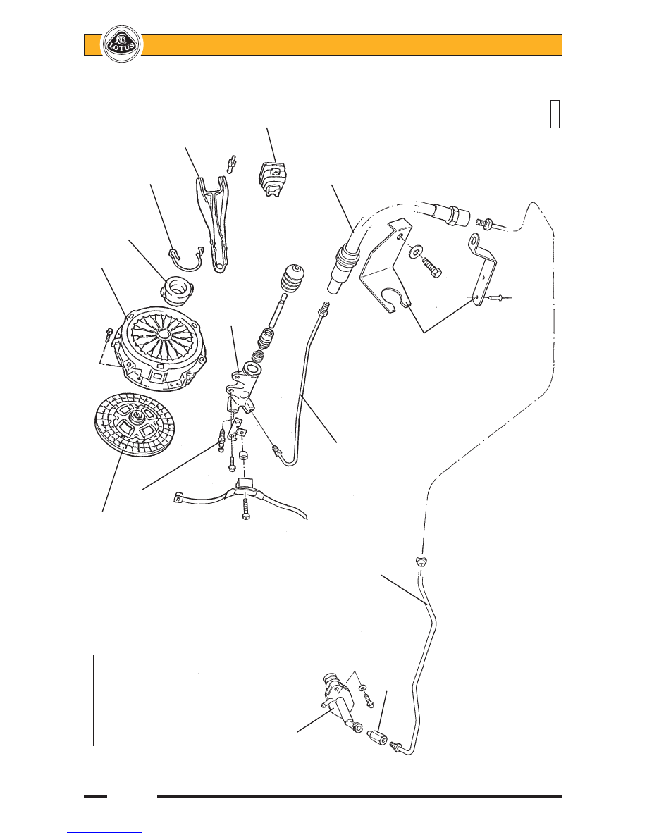
Friction plate

Clutch 

cover

Release bearing

Bleed nipple

Bearing retaining

spring

   Release

    fork

Slave

cylinder

Fork

gaiter

Master cylinder

Flexible hose

S

teel pipe

S

teel pipe

Pipe adaptor

Hose abutment

brackets

pl4701mt


Lotus Service Notes                                  Section QH

Page 3

QH.1 - GENERAL DESCRIPTION

The driving element of the clutch assembly consists of the rear face of the engine flywheel, and a pres-

sure plate fixed to the flywheel via the spring diaphragm clutch cover assembly.  The driven element, is a
single, dry, double sided friction plate, splined to the gearbox input shaft, and interposed between the flywheel
and pressure plate.  The diaphragm spring in the clutch cover clamps the friction plate between the pressure
plate and flywheel to provide the drive connection between engine and gearbox.  The gearbox input shaft, on
which the friction plate is free to slide axially, is 'overhung' from the gearbox, with no spigot bearing in the rear
end of the crankshaft.

The hydraulic clutch release mechanism uses a master cylinder fixed to the pedal box, and a slave

cylinder bolted directly to the transmission case.  The master cylinder is connected to the fluid reservoir of the
brake master cylinder, and uses a steel pipe routed along the outside of the LH chassis side rail to connect with
the slave cylinder via a flexible hose.  The slave cylinder operates a release fork which pivots on a ball end
fulcrum pin and presses the release bearing against the inner ends of the diaphragm spring fingers, which pivot
about their fulcrums and relieve the clamping force applied to the pressure plate via the diaphragm outer edge.
The release bearing slides on a guide sleeve surrounding the gearbox input shaft.  A preload spring inside the
slave cylinder applies light pressure to the release lever in order to ensure that contact between the release
bearing and diaphragm spring fingers is maintained.

No routine adjustment of the clutch or release mechanism is required.  The clutch slave cylinder is self

adjusting, with the 'rest' position of the piston dependent on the thickness, or degree of wear, of the friction
plate.  As wear of the friction plate takes place, and its thickness is reduced, the slave cylinder piston is pushed
progressively further back on the return stroke with fluid being returned to the master cylinder reservoir.

QH.2 - CLUTCH PEDAL

The clutch pedal is machined from an aluminium alloy extrusion which is common to the brake and

throttle pedals, with an extruded footpad keyed, bonded and rivetted to the bottom of the pedal.  Synthetic 'top
hat' bushes are used to provide maintenance free articulation on the steel pivot shaft, with a pair of synthetic
bearing rings supporting a cylindrical steel trunnion to actuate the master cylinder pushrod.  Note that the two
synthetic bearing rings may be replaced with the pedal 'in-situ', by using a suitable bolt with clamp washers to
press the rings into position.  Each bush has an outer diameter chamfer at one end to aid insertion.

The master cylinder pushrod is captive in the end of the master cylinder and is screwed fully into the

pedal trunnion.  With the clutch pedal released, there should be a clearance between the pedal and the pedal
box in order to allow the master cylinder to 'top out'.  Conversely, the pedal should contact the floor before the
cylinder 'bottoms out'.

QH.3 - HYDRAULIC RELEASE SYSTEM

Master Cylinder

The clutch master cylinder is mounted on the pedal box, and is accessible from within the front services

compartment.  The cylinder is not equipped with its own fluid reservoir, but instead is linked via hose to the
adjacent brake fluid reservoir.  There is no provision for any servicing of the master cylinder, and if found to be
faulty, the unit should be replaced.

To replace the master cylinder:
-

Clean the master cylinder and surrounding area with methylated spirit.  Do not use petrol or paraffin.

-

Take all necessary precautions to guard against contamination of painted surfaces with brake fluid.

-

Disconnect and immediately plug and cap the hose connection to the fluid reservoir, and the output pipe
connection.

-

From inside the footwell, remove the two bolts securing the cylinder to the pedal box.  Withdraw the
cylinder from the front services compartment.

-

To refit, reverse the removal procedure, taking care to feed the pedal pushrod through the dust boot and
into the end of the master cylinder as the cylinder is positioned.  Tighten the outlet pipe connection to 20
- 24 Nm and bleed the hydraulic system of air.


Lotus Service Notes                                  Section QH

Page 4

Slave Cylinder

The slave cylinder is secured by two bolts directly to the clutch housing on the forward side of the unit,

and operates the clutch fork by a fixed length pushrod.  A bleed nipple is provided by which to bleed air from the
hydraulic system.

Mounting bolts

Slave cylinder

Clutch fork

Bleed nipple

Steel pipe

Hose connection

          q52

Pedal box

Connection to fluid
reservoir

Clutch master cylinder

Mounting bolt

Pedal pushrod

Clutch pipe

          q51

connector


Lotus Service Notes                                  Section QH

Page 5

To replace the slave cylinder:
-

Clean the slave cylinder and surrounding area with methylated spirit.  Do not use petrol or paraffin.

-

Take all necessary precautions to guard against contamination of painted surfaces with brake fluid.

-

Unscrew the pipe union nut from the slave cylinder and drain the hydraulic fluid into a suitable container.
Cap both pipe and cylinder port to limit fluid loss and prevent dirt ingress.

-

Remove the two cylinder retaining bolts and withdraw the cylinder and pushrod assembly.

-

Remove the cylinder boot and pushrod.

-

Tap the cylinder or use a low pressure airline to remove the piston and spring from the cylinder.
CAUTION - Use a workshop towel to protect against hydraulic fluid spray, and protect painted
surfaces from contamination.

-

Thoroughly clean the cylinder bore using hydraulic fluid.  If any scoring, corrosion, damage or wear is
evident, the cylinder assembly should be renewed.

-

When refitting the piston and spring, use Lithium soap based glycol grease on the piston and seal before
carefully inserting the spring and piston into the cylinder.

-

Fit the pushrod into the boot and the boot to the cylinder.

-

Fit the cylinder with the tie wrap bracket to the clutch housing, and torque the two fixing bolts to 12 Nm.

-

Fit the hydraulic pipe to the slave cylinder and torque to 15 Nm.

-

Bleed the hydraulic system and tighten the bleed nipple to 8.4 Nm.

Hydraulic Pipe

A rigid steel pipe is used to convey the hydraulic fluid from the master cylinder to the left hand front corner

of the engine bay.  The pipe is routed through the dash baffle panel and down the LH 'A' post to run along the
outside of the chassis LH main siderail, within the composite sill member, clipped to the heater pipe.  The pipe
terminates at a bracket rivetted to the rear end of the chassis siderail, where it connects to a flexible hose
secured at its other end to a bracket on the clutch housing.  A short steel pipe links this joint to the clutch slave
cylinder, which uses a 'quickfit' push-in connector to aid production line assembly.

Bleed nipple

Slave cylinder

Spring

Piston

Pushrod

Boot

Fixing bolts

Tie wrap bracket

          q53


Content   ..  101  102  103  104   ..