Airbus A318. AIRCRAFT CHARACTERISTICS AIRPORT AND MAINTENANCE PLANNING (2016) - page 1
@AIRBUS
A318
AIRCRAFT CHARACTERISTICS
AIRPORT AND MAINTENANCE PLANNING
AC
The content of this document is the property of Airbus.
It is supplied in confidence and commercial security on its contents must be maintained.
It must not be used for any purpose other than that for which it is supplied, nor may
information contained in it be disclosed to unauthorized persons.
It must not be reproduced in whole or in part without permission in writing from the owners of
the copyright. Requests for reproduction of any data in this document and the media authorized
for it must be addressed to Airbus.
AIRBUS S.A.S.
Customer Services
Technical Data Support and Services
31707 Blagnac Cedex
FRANCE
Issue: Jul
01/02
Rev: May 01/16
@A318
AIRCRAFT CHARACTERISTICS - AIRPORT AND MAINTENANCE PLANNING
HIGHLIGHTS
Revision No. 13 - May 01/16
LOCATIONS
CHG
DESCRIPTIONS OF CHANGE
CODE
CHAPTER 2
Section 2-1
R
Subject 2-1-1
General Aircraft Characteristics Data
R
Section 2-4
R
Subject 2-4-1
Interior Arrangements - Plan View
R
FIGURE Interior Arrangements - Plan
R
REPLACED ”TOURIST CLASS” BY
View - Typical Configuration - Single-
”ECONOMY CLASS” IN LEGEND AND
Class, High Density
IMPROVED LAYOUT.
FIGURE Interior Arrangements - Plan
R
REPLACED ”SUPER FIRST CLASS” BY
View - Typical Configuration - Two-Class
”FIRST CLASS” IN LEGEND AND
IMPROVED LAYOUT.
CHAPTER 3
Section 3-2
R
CHAPTER 5
Section 5-2
Subject 5-2-0
Terminal Operations - Full Servicing Turn
R
Round Time
FIGURE Full Servicing Turn Round Time
R
REVISED TRT CHART FOR FWD AND
Chart
AFT CARGO.
Section 5-4
Subject 5-4-3
Hydraulic Servicing
R
DESCRIPTION TITLE UPDATED
FIGURE Ground Service Connections -
R
REPLACED TITLE ”HYDRAULIC SYSTEM”
Green System Ground Service Panel
BY ”GROUND SERVICE CONNECTIONS”.
ILLUSTRATION REVISED
HIGHLIGHTS
Page 1
May 01/16
@A318
AIRCRAFT CHARACTERISTICS - AIRPORT AND MAINTENANCE PLANNING
LOCATIONS
CHG
DESCRIPTIONS OF CHANGE
CODE
FIGURE Ground Service Connections -
R
REPLACED TITLE ”HYDRAULIC SYSTEM”
Blue System Ground Service Panel
BY ”GROUND SERVICE CONNECTIONS”.
ILLUSTRATION REVISED
FIGURE Ground Service Connections -
R
REPLACED TITLE ”HYDRAULIC SYSTEM”
Yellow System Ground Service Panel
BY ”GROUND SERVICE CONNECTIONS”.
ILLUSTRATION REVISED
FIGURE Ground Service Connections -
N
ADDED ILLUSTRATION OF RAM AIR
RAT
TURBINE.
ILLUSTRATION ADDED
Section 5-7
Subject 5-7-0
FIGURE Preconditioned Airflow
R
ADDED THE CONDITIONS OF
Requirements
RECIRCULATION FANS AT MAXIMUM
AIRFLOW AND DELETED THE EXAMPLE.
CHAPTER 7
Section 7-2
Subject 7-2-0
Landing Gear Footprint
R
FIGURE Landing Gear Footprint
R
ADDED LANDING GEAR FOOTPRINT
DATA FOR WV009 AND WV010.
Section 7-3
Subject 7-3-0
FIGURE Maximum Pavement Loads
R
ADDED WV009 AND WV010 FOR
MAXIMUM PAVEMENT LOADS.
UPDATED THE CONDITIONS OF V(NG)
AND V(MG).
ILLUSTRATION REVISED
Section 7-5
Subject 7-5-0
FIGURE Flexible Pavement Requirements
R
ADDED WV010 IN FIGURE TITLE.
- WV005, WV010, MRW 68 400 kg, CG
32 %
Section 7-7
Subject 7-7-0
HIGHLIGHTS
Page 2
May 01/16
@A318
AIRCRAFT CHARACTERISTICS - AIRPORT AND MAINTENANCE PLANNING
LOCATIONS
CHG
DESCRIPTIONS OF CHANGE
CODE
FIGURE Rigid Pavement Requirements -
R
ADDED WV010 IN FIGURE TITLE.
WV005, WV010, MRW 68 400 kg, CG 32
%
Section 7-9
Subject 7-9-0
Aircraft Classification Number - Flexible
R
and Rigid Pavements
FIGURE Aircraft Classification Number -
R
ADDED ACN DATA FOR WV009 AND
ACN Table
WV010.
FIGURE Aircraft Classification Number -
R
ADDED WV010 IN FIGURE TITLE.
Flexible Pavement - WV005, WV010,
MRW 68 400 kg, CG 32 %
CHAPTER 10
Section 10-0
Subject 10-0-0
FIGURE Front Page
R
UPDATED REVISION DATE.
FIGURE Wheel/Brake Overheat - Wheel
R
IMPROVED LAYOUT.
Safety Area
FIGURE Aircraft Ground Clearances
R
REVISED AIRCRAFT CONFIGURATIONS IN
THE TABLE AND IMPROVED LAYOUT.
HIGHLIGHTS
Page 3
May 01/16
@A318
AIRCRAFT CHARACTERISTICS - AIRPORT AND MAINTENANCE PLANNING
LIST OF EFFECTIVE CONTENT
Revision No.
13 - May
01/16
CONTENT
CHG
LAST REVISION
CODE
DATE
CHAPTER 1
Subject 1-1-0
Purpose
Dec
01/15
Subject 1-2-0
Glossary
May
01/14
CHAPTER 2
Subject 2-1-1
General Aircraft Characteristics Data
R
May
01/16
Subject 2-2-0
General Aircraft Dimensions
May
01/14
FIGURE General Aircraft Dimensions - Wing Tip Fence
May
01/15
Subject 2-3-0
Ground Clearances
May
01/15
FIGURE Ground Clearances - Wing Tip Fence
Dec
01/15
FIGURE Ground Clearances - Trailing Edge Flaps - Extended
May
01/15
FIGURE Ground Clearances - Flap Tracks - Extended
May
01/15
FIGURE Ground Clearances - Flap Tracks - Retracted
May
01/15
FIGURE Ground Clearances - Flap Tracks - 1 + F
May
01/15
FIGURE Ground Clearances - Aileron Down
May
01/15
FIGURE Ground Clearances - Aileron Up
May
01/15
FIGURE Ground Clearances - Spoilers - Extended
May
01/15
FIGURE Ground Clearances - Leading Edge Slats - Extended
May
01/15
Subject 2-4-1
Interior Arrangements - Plan View
R
May
01/16
FIGURE Interior Arrangements - Plan View - Typical Configuration -
R
May
01/16
Single-Class, High Density
L.E.C.
Page 1
May 01/16
@A318
AIRCRAFT CHARACTERISTICS - AIRPORT AND MAINTENANCE PLANNING
CONTENT
CHG
LAST REVISION
CODE
DATE
FIGURE Interior Arrangements - Plan View - Typical Configuration -
R
May
01/16
Two-Class
Subject 2-5-0
Interior Arrangements - Cross Section
May
01/15
FIGURE Interior Arrangements - Cross Section - Economy Class,
6
May
01/15
Abreast - Wider Aisle
FIGURE Interior Arrangements - Cross Section - First-Class
May
01/15
Subject 2-6-0
Cargo Compartments
May
01/14
FIGURE Cargo Compartments - Locations and Dimensions
May
01/15
Subject 2-7-0
Door Clearances
May
01/15
FIGURE Door Identification and Location - Door Identification
May
01/15
FIGURE Doors Clearances - Forward Passenger/Crew Doors
May
01/15
FIGURE Doors Clearances - Emergency Exits
May
01/15
FIGURE Doors Clearances - Aft Passenger/Crew Doors
May
01/15
FIGURE Doors Clearances - Forward Cargo Compartment Door
May
01/15
FIGURE Doors Clearances - Aft Cargo Compartment Door
May
01/15
FIGURE Doors Clearances - Main Landing Gear Doors
May
01/15
FIGURE Doors Clearances - Radome
May
01/15
FIGURE Doors Clearances - APU and Nose Landing Gear Doors
May
01/15
Subject 2-8-0
Escape Slides
Dec
01/15
FIGURE Escape Slides - Location
Dec
01/15
FIGURE Escape Slides - Dimensions
Dec
01/15
Subject 2-9-0
Landing Gear
May
01/14
FIGURE Landing Gear - Main Landing Gear - Twin-Wheel
May
01/14
FIGURE Landing Gear - Main Landing Gear Dimensions - Twin-Wheel
May
01/14
FIGURE Landing Gear - Nose Landing Gear
May
01/14
L.E.C.
Page 2
May 01/16
@A318
AIRCRAFT CHARACTERISTICS - AIRPORT AND MAINTENANCE PLANNING
CONTENT
CHG
LAST REVISION
CODE
DATE
FIGURE Landing Gear - Nose Landing Gear Dimensions
May
01/14
Landing Gear Maintenance Pits
May
01/14
FIGURE Landing Gear Maintenance Pits - Maintenance Pit Envelopes
May
01/14
FIGURE Landing Gear Maintenance Pits - Maintenance Pit Envelopes
May
01/14
Subject 2-10-0
Exterior Lighting
May
01/15
FIGURE Exterior Lighting
May
01/15
FIGURE Exterior Lighting
May
01/15
FIGURE Exterior Lighting
May
01/15
FIGURE Exterior Lighting
May
01/15
Subject 2-11-0
Antennas and Probes Location
May
01/14
FIGURE Antennas and Probes - Location
May
01/14
Subject 2-12-0
Auxiliary Power Unit
May
01/14
FIGURE Auxiliary Power Unit - Access Doors
Dec
01/15
FIGURE Auxiliary Power Unit - General Layout
Dec
01/15
Engine and Nacelle
May
01/14
FIGURE Power Plant Handling - Major Dimensions - CFM56
Series
May
01/14
Engine
FIGURE Power Plant Handling - Major Dimensions - CFM56
Series
May
01/14
Engine
FIGURE Power Plant Handling - Fan Cowls - CFM56 Series Engine
May
01/14
FIGURE Power Plant Handling - Thrust Reverser Cowls - CFM56
May
01/14
Series Engine
FIGURE Power Plant Handling - Major Dimensions - PW 6000 Series
May
01/14
Engine
FIGURE Power Plant Handling - Nacelle Dimensions - PW 6000
May
01/14
Series Engine
FIGURE Power Plant Handling - Fan Cowls - PW 6000 Series Engine
May
01/14
L.E.C.
Page 3
May 01/16
@A318
AIRCRAFT CHARACTERISTICS - AIRPORT AND MAINTENANCE PLANNING
CONTENT
CHG
LAST REVISION
CODE
DATE
FIGURE Power Plant Handling - Thrust Reverser Halves - PW 6000
May
01/14
Series Engine
Subject 2-13-0
Leveling, Symmetry and Alignment
May
01/14
FIGURE Location of the Leveling Points
May
01/14
Subject 2-14-0
Jacking for Maintenance
May
01/14
FIGURE Jacking for Maintenance - Jacking Point Locations
May
01/15
FIGURE Jacking for Maintenance - Forward Jacking Point
May
01/14
FIGURE Jacking for Maintenance - Wing Jacking Points
May
01/14
FIGURE Jacking for Maintenance - Safety Stay
May
01/15
FIGURE Jacking for Maintenance - Jacking Design
May
01/15
Jacking of the Landing Gear
May
01/14
FIGURE Jacking of the Landing Gear - MLG Jacking Point Location -
May
01/14
Twin Wheels
FIGURE Jacking of the Landing Gear - MLG Jacking with Cantilever
May
01/14
Jack - Twin Wheels
FIGURE Jacking of the Landing Gear - Loads at MLG Jacking Points
May
01/14
- Twin Wheels
FIGURE Jacking of the Landing Gear - NLG Jacking - Point Location
May
01/14
FIGURE Jacking of the Landing Gear - Loads at NLG Jacking Points
May
01/14
CHAPTER 3
Subject 3-1-0
General Information
May
01/14
Subject 3-2-1
Payload/Range - ISA Conditions
May
01/15
FIGURE Payload/Range - ISA Conditions
May
01/15
Subject 3-3-1
Take-Off Weight Limitation - ISA Conditions
May
01/14
L.E.C.
Page 4
May 01/16
@A318
AIRCRAFT CHARACTERISTICS - AIRPORT AND MAINTENANCE PLANNING
CONTENT
CHG
LAST REVISION
CODE
DATE
FIGURE Take-Off Weight Limitation - ISA Conditions - CFM56
May
01/14
Series Engine
FIGURE Take-Off Weight Limitation - ISA Conditions - PW 6000
May
01/14
Series Engine
Subject 3-3-2
Take-Off Weight Limitation - ISA +15˚C (+59˚F) Conditions
May
01/14
FIGURE Take-Off Weight Limitation - ISA +15˚C (+59˚F)
May
01/14
Conditions - CFM56 Series Engine
FIGURE Take-Off Weight Limitation - ISA +15˚C (+59˚F)
May
01/14
Conditions - PW 6000 Series Engine
Subject 3-4-1
Landing Field Length - ISA Conditions
May
01/14
FIGURE Landing Field Length - ISA Conditions - CFM56-5B Series
May
01/14
Engine
FIGURE Landing Field Length - ISA Conditions - PW
6000
Series
May
01/14
Engine
Subject 3-5-0
Final Approach Speed
May
01/14
CHAPTER 4
Subject 4-1-0
General Information
May
01/14
Subject 4-2-0
Turning Radii
Dec
01/15
FIGURE Turning Radii, No Slip Angle - (Sheet 1)
Dec
01/15
FIGURE Turning Radii, No Slip Angle - (Sheet 2)
Dec
01/15
Subject 4-3-0
Minimum Turning Radii
Dec
01/15
FIGURE Minimum Turning Radii
Dec
01/15
Subject 4-4-0
Visibility from Cockpit in Static Position
May
01/14
FIGURE Visibility from Cockpit in Static Position
May
01/14
L.E.C.
Page 5
May 01/16
@A318
AIRCRAFT CHARACTERISTICS - AIRPORT AND MAINTENANCE PLANNING
CONTENT
CHG
LAST REVISION
CODE
DATE
FIGURE Binocular Visibility Through Windows from Captain Eye
May
01/14
Position
Subject 4-5-0
Runway and Taxiway Turn Paths
May
01/14
Subject 4-5-1
135˚ Turn - Runway to Taxiway
May
01/14
FIGURE 135˚ Turn - Runway to Taxiway - Cockpit Over Centerline
May
01/14
Method
FIGURE 135˚ Turn - Runway to Taxiway - Judgemental Oversteering
May
01/14
Method
Subject 4-5-2
90˚ Turn - Runway to Taxiway
May
01/14
FIGURE 90˚ Turn - Runway to Taxiway - Cockpit Over Centerline
May
01/14
Method
FIGURE 90˚ Turn - Runway to Taxiway - Judgemental Oversteering
May
01/14
Method
Subject 4-5-3
180˚ Turn on a Runway
Dec
01/15
FIGURE 180˚ Turn on a Runway - Edge of Runway Method
Dec
01/15
Subject 4-5-4
135˚ Turn - Taxiway to Taxiway
May
01/14
FIGURE 135˚ Turn - Taxiway to Taxiway - Cockpit Over Centerline
May
01/14
Method
Subject 4-5-5
90˚ Turn - Taxiway to Taxiway
May
01/14
FIGURE 90˚ Turn - Taxiway to Taxiway - Cockpit Over Centerline
May
01/14
Method
Subject 4-6-0
Runway Holding Bay (Apron)
May
01/14
FIGURE Runway Holding Bay (Apron)
May
01/14
Subject 4-7-0
Minimum Line-Up Distance Corrections
May
01/14
L.E.C.
Page 6
May 01/16
@A318
AIRCRAFT CHARACTERISTICS - AIRPORT AND MAINTENANCE PLANNING
CONTENT
CHG
LAST REVISION
CODE
DATE
FIGURE Minimum Line-Up Distance Corrections - 90˚ Turn on
May
01/14
Runway Entry
FIGURE Minimum Line-Up Distance Corrections - 180˚ Turn on
May
01/14
Runway Turn Pad
FIGURE Minimum Line-Up Distance Corrections - 180˚ Turn on
May
01/14
Runway Width
Subject 4-8-0
Aircraft Mooring
May
01/14
FIGURE Aircraft Mooring
May
01/14
CHAPTER 5
Subject 5-1-1
Aircraft Servicing Arrangements
May
01/14
Subject 5-1-2
Typical Ramp Layout - Open Apron
May
01/14
FIGURE Typical Ramp Layout - Open Apron - Bulk Loading
May
01/15
Subject 5-1-3
Typical Ramp Layout - Gate
May
01/14
FIGURE Typical Ramp Layout - Gate
May
01/15
Subject 5-2-0
Terminal Operations - Full Servicing Turn Round Time
R
May
01/16
FIGURE Full Servicing Turn Round Time Chart
R
May
01/16
Subject 5-3-0
Terminal Operations - Outstation Turn Round Time
May
01/14
FIGURE Outstation Turn Round Time Chart
May
01/14
Subject 5-4-1
Ground Service Connections Layout
May
01/14
FIGURE Ground Service Connections Layout
May
01/14
Subject 5-4-2
Grounding (Earthing) Points
May
01/14
L.E.C.
Page 7
May 01/16
@A318
AIRCRAFT CHARACTERISTICS - AIRPORT AND MAINTENANCE PLANNING
CONTENT
CHG
LAST REVISION
CODE
DATE
FIGURE Ground Service Connections - Grounding (Earthing) Points -
May
01/14
Landing Gear
FIGURE Ground Service Connections - Grounding (Earthing) Points -
May
01/14
Wing (If Installed)
FIGURE Ground Service Connections - Grounding (Earthing) Point -
May
01/14
Avionics Compartment Door-Frame
FIGURE Ground Service Connections - Grounding (Earthing) Point -
May
01/14
Engine Air Intake (If Installed)
Subject 5-4-3
Hydraulic Servicing
R
May
01/16
FIGURE Ground Service Connections - Green System Ground Service
R
May
01/16
Panel
FIGURE Ground Service Connections - Blue System Ground Service
R
May
01/16
Panel
FIGURE Ground Service Connections - Yellow System Ground Service
R
May
01/16
Panel
FIGURE Ground Service Connections - RAT
N
May
01/16
Subject 5-4-4
Electrical System
May
01/15
FIGURE Ground Service Connections - External Power Receptacles
May
01/14
Subject 5-4-5
Oxygen System
May
01/14
FIGURE Ground Service Connections - Oxygen System
May
01/14
Subject 5-4-6
Fuel System
May
01/14
FIGURE Ground Service Connections - Refuel/Defuel Control Panel
May
01/14
FIGURE Ground Service Connections - Refuel/Defuel Couplings
May
01/14
FIGURE Ground Service Connections - Overwing Gravity-Refuel Cap
May
01/14
(If Installed)
FIGURE Ground Service Connections - Overpressure Protectors and
May
01/14
NACA Vent Intake
Subject 5-4-7
L.E.C.
Page 8
May 01/16
@A318
AIRCRAFT CHARACTERISTICS - AIRPORT AND MAINTENANCE PLANNING
CONTENT
CHG
LAST REVISION
CODE
DATE
Pneumatic System
May
01/14
FIGURE Ground Service Connections - LP and HP Ground
May
01/14
Connectors
Subject 5-4-8
Oil System
May
01/14
FIGURE Ground Service Connections - Engine Oil Tank -- CFM56
May
01/14
Series Engine
FIGURE Ground Service Connections - IDG Oil Tank -- CFM56 Series
May
01/14
Engine
FIGURE Ground Service Connections - Starter Oil Tank -- CFM56
May
01/14
Series Engine
FIGURE Ground Service Connections - Engine Oil Tank -- PW6000
May
01/14
Series Engine
FIGURE Ground Service Connections - IDG Oil Tank -- PW6000
May
01/14
Series Engine
FIGURE Ground Service Connections - Starter Oil Tank -- PW6000
May
01/14
Series Engine
FIGURE Ground Service Connections - APU Oil Tank
May
01/14
Subject 5-4-9
Potable Water System
May
01/14
FIGURE Ground Service Connections - Potable Water Ground Service
May
01/14
Panels
FIGURE Ground Service Connections - Potable Water Tank Location
May
01/14
Subject 5-4-10
Vacuum Toilet System
May
01/14
FIGURE Ground Service Connections - Waste Water Ground Service
May
01/14
Panel
FIGURE Ground Service Connections - Waste Tank Location
May
01/14
Subject 5-5-0
Engine Starting Pneumatic Requirements
May
01/14
FIGURE Example for Use of the Charts
May
01/14
L.E.C.
Page 9
May 01/16
@A318
AIRCRAFT CHARACTERISTICS - AIRPORT AND MAINTENANCE PLANNING
CONTENT
CHG
LAST REVISION
CODE
DATE
FIGURE Engine Starting Pneumatic Requirements - PW 6000 Series
May
01/14
Engine
FIGURE Engine Starting Pneumatic Requirements - CFM56
Series
May
01/14
Engine
Subject 5-6-0
Ground Pneumatic Power Requirements
May
01/15
FIGURE Ground Pneumatic Power Requirements - Heating
May
01/14
FIGURE Ground Pneumatic Power Requirements - Cooling
May
01/14
Subject 5-7-0
Preconditioned Airflow Requirements
May
01/15
FIGURE Preconditioned Airflow Requirements
R
May
01/16
Subject 5-8-0
Ground Towing Requirements
May
01/15
FIGURE Ground Towing Requirements
May
01/15
Subject 5-9-0
De-Icing and External Cleaning
May
01/15
CHAPTER 6
Subject 6-1-0
Engine Exhaust Velocities and Temperatures
Dec
01/15
Subject 6-1-1
Engine Exhaust Velocities Contours - Ground Idle Power
Dec
01/15
FIGURE Engine Exhaust Velocities - Ground Idle Power -- CFM56
Dec
01/15
Series Engine
FIGURE Engine Exhaust Velocities - Ground Idle Power -- PW 6000
Dec
01/15
Series Engine
Subject 6-1-2
Engine Exhaust Temperatures Contours - Ground Idle Power
Dec
01/15
FIGURE Engine Exhaust Temperatures - Ground Idle Power -- CFM56
Dec
01/15
Series Engine
FIGURE Engine Exhaust Temperatures - Ground Idle Power -- PW
Dec
01/15
6000 Series Engine
L.E.C.
Page 10
May 01/16
@A318
AIRCRAFT CHARACTERISTICS - AIRPORT AND MAINTENANCE PLANNING
CONTENT
CHG
LAST REVISION
CODE
DATE
Subject 6-1-3
Engine Exhaust Velocities Contours - Breakaway Power
Dec
01/15
FIGURE Engine Exhaust Velocities - Breakaway Power -- CFM56
Dec
01/15
Series Engine
FIGURE Engine Exhaust Velocities - Breakaway Power -- PW 6000
Dec
01/15
Series Engine
Subject 6-1-4
Engine Exhaust Temperatures Contours - Breakaway Power
Dec
01/15
FIGURE Engine Exhaust Temperatures - Breakaway Power -- CFM56
Dec
01/15
Series Engine
FIGURE Engine Exhaust Temperatures - Breakaway Power -- PW
Dec
01/15
6000 Series Engine
Subject 6-1-5
Engine Exhaust Velocities Contours - Takeoff Power
Dec
01/15
FIGURE Engine Exhaust Velocities - Takeoff Power -- CFM56 Series
Dec
01/15
Engine
FIGURE Engine Exhaust Velocities - Takeoff Power -- PW 6000 Series
Dec
01/15
Engine
Subject 6-1-6
Engine Exhaust Temperatures Contours - Takeoff Power
Dec
01/15
FIGURE Engine Exhaust Temperatures - Takeoff Power -- CFM56
Dec
01/15
Series Engine
FIGURE Engine Exhaust Temperatures - Takeoff Power -- PW 6000
Dec
01/15
Series Engine
Subject 6-3-0
Danger Areas of Engines
May
01/14
Subject 6-3-1
Ground Idle Power
Dec
01/15
FIGURE Danger Areas of the Engines - CFM56 Series Engine
May
01/15
FIGURE Danger Areas of the Engines - PW 6000 Series Engine
May
01/15
Subject 6-3-2
L.E.C.
Page 11
May 01/16
@A318
AIRCRAFT CHARACTERISTICS - AIRPORT AND MAINTENANCE PLANNING
CONTENT
CHG
LAST REVISION
CODE
DATE
Takeoff Power
Dec
01/15
FIGURE Danger Areas of the Engines - CFM56 Series Engine
Dec
01/15
FIGURE Danger Areas of the Engines - PW 6000 Series Engine
Dec
01/15
Subject 6-4-1
APU - APIC & GARRETT
May
01/14
FIGURE Exhaust Velocities and Temperatures - APU -- APIC &
May
01/14
GARRETT
CHAPTER 7
Subject 7-1-0
General Information
May
01/15
Subject 7-2-0
Landing Gear Footprint
R
May
01/16
FIGURE Landing Gear Footprint
R
May
01/16
Subject 7-3-0
Maximum Pavement Loads
May
01/15
FIGURE Maximum Pavement Loads
R
May
01/16
Subject 7-4-0
Landing Gear Loading on Pavement
May
01/15
FIGURE Landing Gear Loading on Pavement - WV006, MRW
56
400
May
01/14
kg, CG 35%
FIGURE Landing Gear Loading on Pavement - WV005, MRW
68
400
May
01/14
kg, CG 32%
Subject 7-5-0
Flexible Pavement Requirements - US Army Corps of Engineers
May
01/15
Design Method
FIGURE Flexible Pavement Requirements - WV006, MRW 56 400 kg,
May
01/14
CG 35 %
FIGURE Flexible Pavement Requirements - WV005, WV010, MRW
R
May
01/16
68 400 kg, CG 32 %
Subject 7-6-0
Flexible Pavement Requirements - LCN Conversion
May
01/15
L.E.C.
Page 12
May 01/16
@A318
AIRCRAFT CHARACTERISTICS - AIRPORT AND MAINTENANCE PLANNING
CONTENT
CHG
LAST REVISION
CODE
DATE
Subject 7-7-0
Rigid Pavement Requirements - Portland Cement Association Design
May
01/15
Method
FIGURE Rigid Pavement Requirements - WV006, MRW 56 400 kg,
May
01/14
CG 35 %
FIGURE Rigid Pavement Requirements - WV005, WV010, MRW 68
R
May
01/16
400 kg, CG 32 %
Subject 7-8-0
Rigid Pavement Requirements - LCN Conversion
May
01/15
Subject 7-9-0
Aircraft Classification Number - Flexible and Rigid Pavements
R
May
01/16
FIGURE Aircraft Classification Number - ACN Table
R
May
01/16
FIGURE Aircraft Classification Number - Flexible Pavement - WV006,
May
01/14
MRW 56 400 kg, CG 35 %
FIGURE Aircraft Classification Number - Flexible Pavement - WV005,
R
May
01/16
WV010, MRW 68 400 kg, CG 32 %
CHAPTER 8
Subject 8-0-0
Scaled Drawings
May
01/14
FIGURE Scaled Drawing
May
01/14
CHAPTER 10
Subject 10-0-0
Aircraft Rescue and Fire Fighting
May
01/15
FIGURE Front Page
R
May
01/16
FIGURE Highly Flammable and Hazardous Materials and Components
May
01/15
FIGURE Batteries Location and Access
May
01/15
FIGURE Wheel/Brake Overheat - Wheel Safety Area
R
May
01/16
FIGURE Composite Materials
May
01/15
FIGURE L/G Ground Lock Safety Devices
May
01/14
FIGURE Emergency Evacuation Devices
Dec
01/15
L.E.C.
Page 13
May 01/16
@A318
AIRCRAFT CHARACTERISTICS - AIRPORT AND MAINTENANCE PLANNING
CONTENT
CHG LAST REVISION
CODE
DATE
FIGURE Pax/Crew Doors
May 01/14
FIGURE Emergency Exit Hatch
May 01/14
FIGURE FWD and AFT Lower Deck Cargo Doors
May 01/14
FIGURE Control Panels
May 01/14
FIGURE APU Access Door
May 01/14
FIGURE Aircraft Ground Clearances
R
May 01/16
FIGURE Structural Break-in Points
May 01/14
L.E.C.
Page 14
May 01/16
@A318
AIRCRAFT CHARACTERISTICS - AIRPORT AND MAINTENANCE PLANNING
TABLE OF CONTENTS
1
SCOPE
1-1-0
Introduction
1-2-0
Glossary
2
AIRCRAFT DESCRIPTION
2-1-1
General Aircraft Characteristics Data
2-2-0
General Aircraft Dimensions
2-3-0
Ground Clearances
2-4-1
Interior Arrangements - Plan View
2-5-0
Interior Arrangements - Cross Section
2-6-0
Cargo Compartments
2-7-0
Door Clearances and Location
2-8-0
Escape Slides
2-9-0
Landing Gear
2-10-0
Exterior Lighting
2-11-0
Antennas and Probes Location
2-12-0
Power Plant
2-13-0
Leveling, Symmetry and Alignment
2-14-0
Jacking
3
AIRCRAFT PERFORMANCE
3-1-0
General Information
3-2-1
Payload / Range - ISA Conditions
3-3-1
Take-off Weight Limitation - ISA Conditions
3-3-2
Take-off Weight Limitation - ISA +15˚C (+59˚F) Conditions
3-4-1
Landing Field Length - ISA Conditions
3-5-0
Final Approach Speed
4
GROUND MANEUVERING
4-1-0
General Information
4-2-0
Turning Radii
4-3-0
Minimum Turning Radii
4-4-0
Visibility from Cockpit in Static Position
4-5-0
Runway and Taxiway Turn Paths
4-5-1
135˚ Turn - Runway to Taxiway
T.O.C.
Page 1
May 01/16
@A318
AIRCRAFT CHARACTERISTICS - AIRPORT AND MAINTENANCE PLANNING
4-5-2
90˚ Turn - Runway to Taxiway
4-5-3
180˚ Turn on a Runway
4-5-4
135˚ Turn - Taxiway to Taxiway
4-5-5
90˚ Turn - Taxiway to Taxiway
4-6-0
Runway Holding Bay (Apron)
4-7-0
Minimum Line-Up Distance Corrections
4-8-0
Aircraft Mooring
5
TERMINAL SERVICING
5-1-1
Aircraft Servicing Arrangements
5-1-2
Typical Ramp Layout - Open Apron
5-1-3
Typical Ramp Layout - Gate
5-2-0
Terminal Operations - Full Servicing Turn Round Time Chart
5-3-0
Terminal Operation - Outstation Turn Round Time Chart
5-4-1
Ground Service Connections
5-4-2
Grounding Points
5-4-3
Hydraulic System
5-4-4
Electrical System
5-4-5
Oxygen System
5-4-6
Fuel System
5-4-7
Pneumatic System
5-4-8
Oil System
5-4-9
Potable Water System
5-4-10
Waste Water System
5-5-0
Engine Starting Pneumatic Requirements
5-6-0
Ground Pneumatic Power Requirements
5-7-0
Preconditioned Airflow Requirements
5-8-0
Ground Towing Requirements
5-9-0
De-Icing and External Cleaning
6
OPERATING CONDITIONS
6-1-0
Engine Exhaust Velocities and Temperatures
6-1-1
Engine Exhaust Velocities Contours - Ground Idle Power
6-1-2
Engine Exhaust Temperatures Contours - Ground Idle Power
6-1-3
Engine Exhaust Velocities Contours - Breakaway Power
6-1-4
Engine Exhaust Temperatures Contours - Breakaway Power
6-1-5
Engine Exhaust Velocities Contours - Takeoff Power
6-1-6
Engine Exhaust Temperatures Contours - Takeoff Power
T.O.C.
Page 2
May 01/16
@A318
AIRCRAFT CHARACTERISTICS - AIRPORT AND MAINTENANCE PLANNING
6-3-0
Danger Areas of Engines
6-3-1
Ground Idle Power
6-3-2
Takeoff Power
6-4-1
APU
7
PAVEMENT DATA
7-1-0
General Information
7-2-0
Landing Gear Footprint
7-3-0
Maximum Pavement Loads
7-4-0
Landing Gear Loading on Pavement
7-5-0
Flexible Pavement Requirements - U.S. Army Corps of Engineers Design Method
7-6-0
Flexible Pavement Requirements - LCN Conversion
7-7-0
Rigid Pavement Requirements - Portland Cement Association Design Method
7-8-0
Rigid Pavement Requirements - LCN Conversion
7-9-0
ACN/PCN Reporting System - Flexible and Rigid Pavements
8
SCALED DRAWINGS
8-0-0
SCALED DRAWINGS
10
AIRCRAFT RESCUE AND FIRE FIGHTING
10-0-0
AIRCRAFT RESCUE AND FIRE FIGHTING
T.O.C.
Page 3
May 01/16
@A318
AIRCRAFT CHARACTERISTICS - AIRPORT AND MAINTENANCE PLANNING
SCOPE
1-1-0
Introduction
**ON A/C A318-100
Purpose
1.
General
The A318 AIRCRAFT CHARACTERISTICS -- AIRPORT AND MAINTENANCE PLANNING (AC)
manual is issued for the A318-100 series aircraft equipped with wing-tip fences, to provide necessary
data to airport operators, airlines and Maintenance/Repair Organizations (MRO) for airport and
maintenance facilities planning.
This document is not customized and must not be used for training purposes. No information within
may constitute a contractual commitment.
The A320 Family is the world’s best-selling single-aisle aircraft. An A320 takes off or lands
somewhere in the world every 2.5 seconds of every day, the family has logged more than 50 million
cycles since entry-into-service and records a best-in-class dispatch reliability of 99.7%.
Correspondence concerning this publication should be directed to:
AIRBUS S.A.S.
Customer Services
Technical Data Support and Services
1, Rond Point Maurice BELLONTE
31707 BLAGNAC CEDEX
FRANCE
Page 1
May 01/16
1-1-0
@A318
AIRCRAFT CHARACTERISTICS - AIRPORT AND MAINTENANCE PLANNING
1-2-0
Glossary
**ON A/C A318-100
Glossary
1.
List of Abbreviations
A/C
Aircraft
ACN
Aircraft Classification Number
AMM
Aircraft Maintenance Manual
APU
Auxiliary Power Unit
B/C
Business Class
CBR
California Bearing Ratio
CC
Cargo Compartment
CG
Center of Gravity
CKPT
Cockpit
E
Young’s Modulus
ELEC
Electric, Electrical, Electricity
ESWL
Equivalent Single Wheel Load
FAA
Federal Aviation Administration
F/C
First Class
FDL
Fuselage Datum Line
FR
Frame
FSTE
Full Size Trolley Equivalent
FWD
Forward
GPU
Ground Power Unit
GSE
Ground Support Equipment
HYD
Hydraulic
ICAO
International Civil Aviation Organisation
IDG
Integrated Drive Generator
ISA
International Standard Atmosphere
L
Left
L
Radius of relative stiffness
LCN
Load Classification Number
LD
Lower Deck
L/G
Landing Gear
LH
Left Hand
LPS
Last Pax Seating
MAC
Mean Aerodynamic Chord
MAX
Maximum
Page 1
May 01/16
1-2-0
@A318
AIRCRAFT CHARACTERISTICS - AIRPORT AND MAINTENANCE PLANNING
MIN
Minimum
MLG
Main Landing Gear
NLG
Nose Landing Gear
OAT
Outside Air Temperature
PAX
Passenger
PBB
Passenger Boarding Bridge
PCA
Portland Cement Association
PCN
Pavement Classification Number
PRM
Passenger with Reduced Mobility
R
Right
RH
Right Hand
ULD
Unit Load Device
US
United States
WV
Weight Variant
Y/C
Tourist Class
2.
Design Weight Terminology
-
Maximum Design Ramp Weight (MRW):
Maximum weight for ground maneuver (including weight of taxi and run-up fuel) as limited by
aircraft strength and airworthiness requirements. It is also called Maximum Design Taxi Weight
(MTW).
-
Maximum Design Landing Weight (MLW):
Maximum weight for landing as limited by aircraft strength and airworthiness requirements.
-
Maximum Design Takeoff Weight (MTOW):
Maximum weight for takeoff as limited by aircraft strength and airworthiness requirements. (This
is the maximum weight at start of the take-off run).
-
Maximum Design Zero Fuel Weight (MZFW):
Maximum permissible weight of the aircraft without usable fuel.
-
Maximum Seating Capacity:
Maximum number of passengers specifically certified or anticipated for certification.
-
Usable Volume:
Usable volume available for cargo, pressurized fuselage, passenger compartment and cockpit.
-
Water Volume:
Maximum volume of cargo compartment.
-
Usable Fuel:
Fuel available for aircraft propulsion.
Page 2
May 01/16
1-2-0
@A318
AIRCRAFT CHARACTERISTICS - AIRPORT AND MAINTENANCE PLANNING
AIRCRAFT DESCRIPTION
2-1-1
General Aircraft Characteristics Data
**ON A/C A318-100
General Aircraft Characteristics Data
1.
The following table provides characteristics of A318-100 Models, these data are specific to each
Weight Variant:
Aircraft Characteristics
WV000
WV001
WV002
WV003
Maximum Ramp Weight (MRW)
59 400 kg
61 900 kg
63 400 kg
64 900 kg
Maximum Taxi Weight (MTW)
(130 955 lb)
(136 466 lb)
(139 773 lb)
(143 080 lb)
Maximum Take-Off Weight
59 000 kg
61 500 kg
63 000 kg
64 500 kg
(MTOW)
(130 073 lb)
(135 584 lb)
(138 891 lb)
(142 198 lb)
Maximum Landing Weight (MLW)
56 000 kg
56 000 kg
57 500 kg
57 500 kg
(123 459 lb)
(123 459 lb)
(126 766 lb)
(126 766 lb)
Maximum Zero Fuel Weight
53 000 kg
53 000 kg
54 500 kg
54 500 kg
(MZFW)
(116 845 lb)
(116 845 lb)
(120 152 lb)
(120 152 lb)
Aircraft Characteristics
WV004
WV005
WV006
WV007
Maximum Ramp Weight (MRW)
66 400 kg
68 400 kg
56 400 kg
61 400 kg
Maximum Taxi Weight (MTW)
(146 387 lb)
(150 796 lb)
(124 341 lb)
(135 364 lb)
Maximum Take-Off Weight
66 000 kg
68 000 kg
56 000 kg
61 000 kg
(MTOW)
(145 505 lb)
(149 914 lb)
(123 459 lb)
(134 482 lb)
Maximum Landing Weight (MLW)
57 500 kg
57 500 kg
56 000 kg
56 000 kg
(126 766 lb)
(126 766 lb)
(123 459 lb)
(123 459 lb)
Maximum Zero Fuel Weight
54 500 kg
54 500 kg
53 000 kg
53 000 kg
(MZFW)
(120 152 lb)
(120 152 lb)
(116 845 lb)
(116 845 lb)
Aircraft Characteristics
WV008
WV009
WV010
Maximum Ramp Weight
(MRW)
64 400 kg
66 400 kg
68 400 kg
Maximum Taxi Weight
(141 978 lb)
(146 387 lb)
(150 796 lb)
(MTW)
Maximum Take-Off
64 000 kg
66 000 kg
68 000 kg
Weight (MTOW)
(141 096 lb)
(145 505 lb)
(149 914 lb)
Page 1
May 01/16
2-1-1
@A318
AIRCRAFT CHARACTERISTICS - AIRPORT AND MAINTENANCE PLANNING
Aircraft Characteristics
WV008
WV009
WV010
Maximum Landing
56 000 kg
57 500 kg
57 500 kg
Weight (MLW)
(123 459 lb)
(126 766 lb)
(126 766 lb)
Maximum Zero Fuel
53 000 kg
48 000 kg
48 000 kg
Weight (MZFW)
(116 845 lb)
(105 822 lb)
(105 822 lb)
2.
The following table provides characteristics of A318-100 Models, these data are common to each
Weight Variant:
Aircraft Characteristics
Standard Seating Capacity
132
(Single-Class)
Usable Fuel Capacity
23 859 l
(density = 0.785 kg/l)
(6 303 US gal)
18 729 kg
(41 290 lb)
Pressurized Fuselage Volume
257 m3
(A/C non equipped)
(9 076 ft3)
Passenger Compartment
107 m3
Volume
(3 779 ft3)
Cockpit Volume
9m3
(318 ft3)
Usable Volume, FWD CC
6.72 m3
(237 ft3)
Usable Volume, AFT CC
8.87 m3
(313 ft3)
Usable Volume, Bulk CC
5.71 m3
(202 ft3)
Water Volume, FWD CC
8.34 m3
(295 ft3)
Water Volume, AFT CC
10.38 m3
(367 ft3)
Water Volume, Bulk CC
5.97 m3
(211 ft3)
Page 2
May 01/16
2-1-1
@A318
AIRCRAFT CHARACTERISTICS - AIRPORT AND MAINTENANCE PLANNING
2-2-0
General Aircraft Dimensions
**ON A/C A318-100
General Aircraft Dimensions
1.
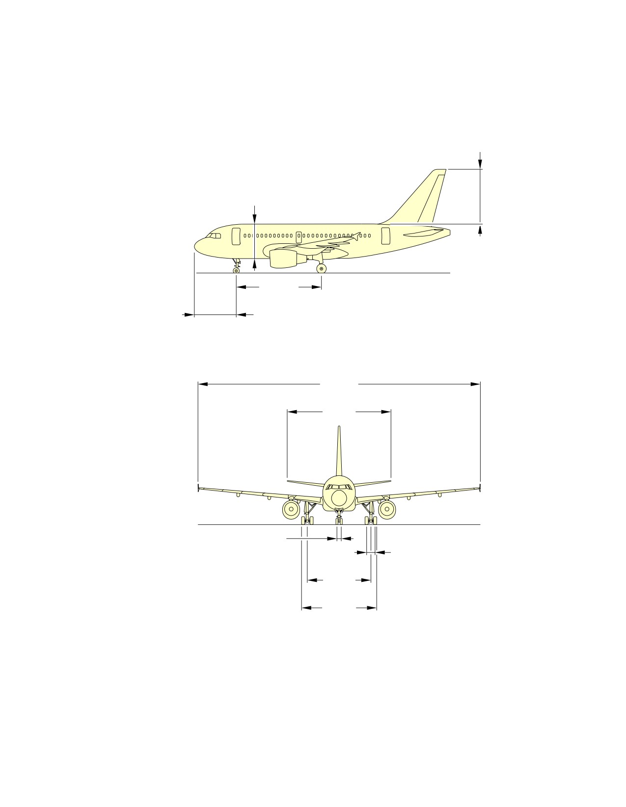
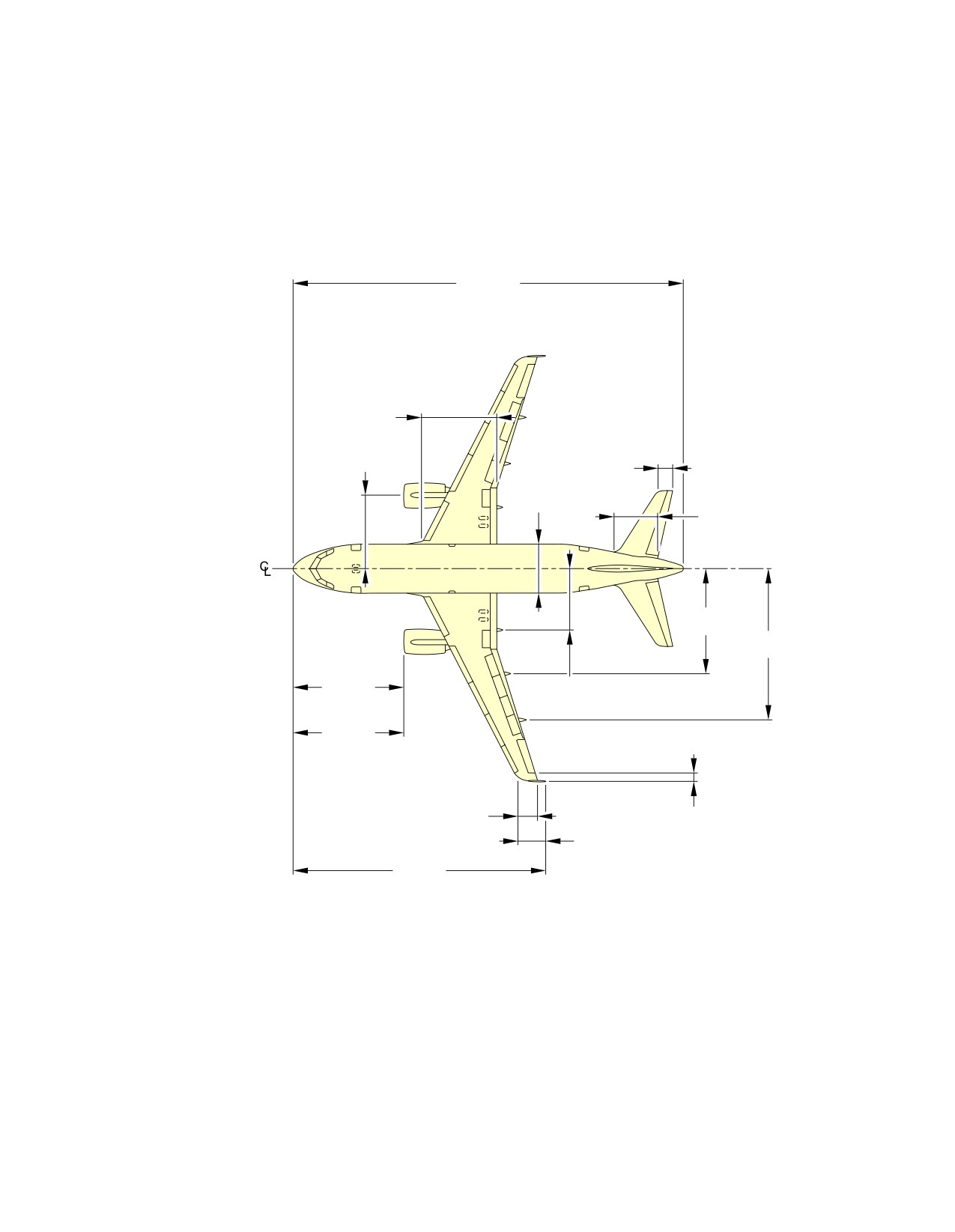
This section provides general aircraft dimensions.
Page 1
May 01/16
2-2-0
@A318
AIRCRAFT CHARACTERISTICS - AIRPORT AND MAINTENANCE PLANNING
**ON A/C A318-100
6.62 m
(21.72 ft)
4.14 m
(13.58 ft)
10.25 m
(33.63 ft)
5.07 m
(16.63 ft)
34.10 m
(111.88 ft)
12.45 m
(40.85 ft)
0.50 m
(1.64 ft)
0.93 m
(3.05 ft)
7.59 m
(24.90 ft)
8.95 m
(29.36 ft)
NOTE:
RELATED TO AIRCRAFT ATTITUDE AND WEIGHT.
N_AC_020200_1_0010101_01_04
General Aircraft Dimensions
Wing Tip Fence (Sheet 1 of 2)
FIGURE-2-2-0-991-001-A01
Page 2
May 01/16
2-2-0
@A318
AIRCRAFT CHARACTERISTICS - AIRPORT AND MAINTENANCE PLANNING
**ON A/C A318-100
31.45 m
(103.18 ft)
6.07 m
(19.91 ft)
5.75 m
1.24 m
(18.86 ft)
(4.07 ft)
3.95 m
(12.96 ft)
3.31 m
(10.86 ft)
8.32 m
(27.30 ft)
11.93 m
(39.14 ft)
8.81 m
4.91 m
CFM56
(28.90 ft)
(16.11 ft)
9.10 m
PW6000
(29.86 ft)
1.50 m
0.76 m
(4.92 ft)
(2.49 ft)
1.82 m
(5.97 ft)
20.07 m
(65.85 ft)
NOTE:
RELATED TO AIRCRAFT ATTITUDE AND WEIGHT.
N_AC_020200_1_0010107_01_02
General Aircraft Dimensions
Wing Tip Fence (Sheet 2 of 2)
FIGURE-2-2-0-991-001-A01
Page 3
May 01/16
2-2-0
@A318
AIRCRAFT CHARACTERISTICS - AIRPORT AND MAINTENANCE PLANNING
2-3-0
Ground Clearances
**ON A/C A318-100
Ground Clearances
1.
This section provides the height of various points of the aircraft, above the ground, for different
aircraft configurations.
Dimensions in the tables are approximate and will vary with tire type, weight and balance and other
special conditions.
The dimensions are given for:
-
A light weight, for an A/C in maintenance configuration with a mid CG,
-
An aircraft at Maximum Ramp Weight with a FWD CG and an AFT CG,
-
Aircraft on jacks, FDL at 4.60 m (15.09 ft).
NOTE : Passenger and cargo door ground clearances are measured from the center of the door sill
and from floor level.
Page 1
May 01/16
2-3-0
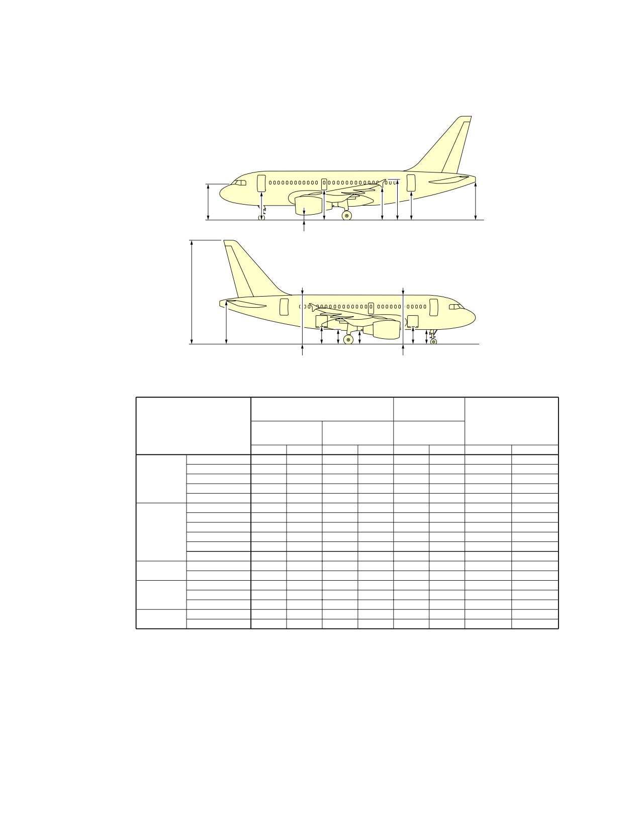
@A318
AIRCRAFT CHARACTERISTICS - AIRPORT AND MAINTENANCE PLANNING
**ON A/C A318-100
CP1
D1
D2
W2 W1 D3
AP
N1
VT
HT
C2 F2
BF1
C1 F1
F4
F3
39 000 kg
MRW
(85 980 lb)
A/C JACKED
A/C CONFIGURATION
FDL = 4.60 m (15.09 ft)
FWD CG (15.8%)
AFT CG (32%)
CG (25%)
m
ft
m
ft
m
ft
m
ft
D1
3.37
11.06
3.42
11.22
3.45
11.32
4.13
13.55
D2
3.90
12.80
3.90
12.80
3.97
13.02
4.54
14.89
DOORS
D3
3.67
12.04
3.60
11.81
3.72
12.20
4.13
13.55
C1
2.00
6.56
2.03
6.66
2.08
6.82
2.71
8.89
C2
2.14
7.02
2.11
6.92
2.20
7.22
2.71
8.89
F1
1.71
5.61
1.74
5.71
1.79
5.87
2.43
7.97
F2
1.87
6.14
1.84
6.04
1.93
6.33
2.43
7.97
F3
5.86
19.23
5.89
19.32
5.93
19.46
6.58
21.59
FUSELAGE
F4
6.02
19.75
5.99
19.65
6.08
19.95
6.58
21.59
BF1
1.67
5.48
1.65
5.41
1.74
5.71
2.26
7.41
CP1
4.13
13.55
4.21
13.81
4.22
13.85
4.96
16.27
W1
4.83
15.85
4.79
15.72
4.89
16.04
5.35
17.55
WINGS
W2
3.86
12.66
3.82
12.53
3.92
12.86
4.38
14.37
HT
5.57
18.27
5.46
17.91
5.62
18.44
5.93
19.46
TAILPLANE
AP
4.87
15.98
4.75
15.58
4.91
16.11
5.20
17.06
VT
12.85
42.16
12.74
41.80
12.89
42.29
13.20
43.31
ENGINE/
N1 (CFM)
0.59
1.94
0.60
1.97
0.66
2.17
1.24
4.07
NACELLE
N1 (PW)
0.71
2.33
0.72
2.36
0.78
2.56
1.36
4.46
NOTE:
PASSENGER AND CARGO DOOR GROUND CLEARANCES ARE MEASURED FROM THE CENTER
OF THE DOOR SILL AND FROM FLOOR LEVEL.
N_AC_020300_1_0010101_01_07
Ground Clearances
Wing Tip Fence
FIGURE-2-3-0-991-001-A01
Page 2
May 01/16
2-3-0
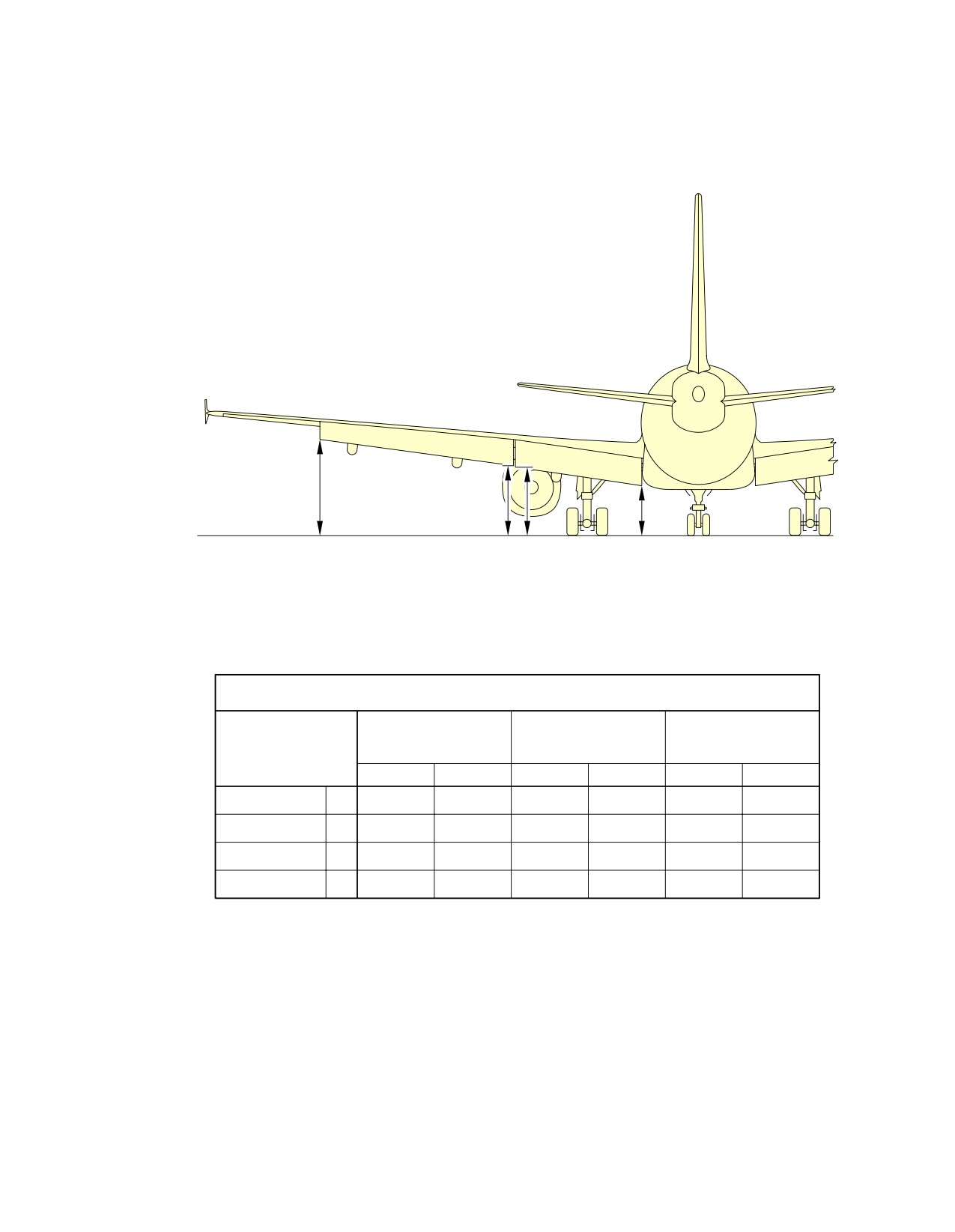
@A318
AIRCRAFT CHARACTERISTICS - AIRPORT AND MAINTENANCE PLANNING
**ON A/C A318-100
D
C
B
A
FLAPS EXTENDED
A/C IN MAINTENANCE
MAXIMUM RAMP
MAXIMUM RAMP
CONFIGURATION
WEIGHT FWD CG
WEIGHT AFT CG
DESCRIPTION
MID CG
m
ft
m
ft
m
ft
FLAP 1 INBD
A
2.05
6.73
1.99
6.53
1.96
6.43
FLAP 1 OUTBD
B
2.77
9.09
2.71
8.89
2.68
8.79
FLAP 2 INBD
C
2.81
9.22
2.75
9.02
2.72
8.92
FLAP 2 OUTBD
D
3.65
11.98
3.60
11.81
3.54
11.61
N_AC_020300_1_0060101_01_01
Ground Clearances
Trailing Edge Flaps - Extended
FIGURE-2-3-0-991-006-A01
Page 3
May 01/16
2-3-0
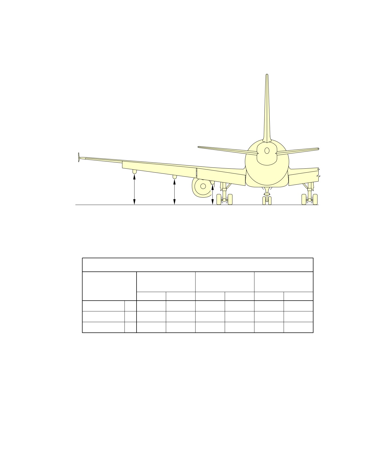
@A318
AIRCRAFT CHARACTERISTICS - AIRPORT AND MAINTENANCE PLANNING
**ON A/C A318-100
C
B
A
FLAP TRACKS EXTENDED
A/C IN MAINTENANCE
MAXIMUM RAMP
MAXIMUM RAMP
CONFIGURATION
WEIGHT FWD CG
WEIGHT AFT CG
DESCRIPTION
MID CG
m
ft
m
ft
m
ft
FLAP TRACK 2
A
2.10
6.89
2.03
6.66
2.00
6.56
FLAP TRACK 3
B
2.59
8.50
2.53
8.30
2.49
8.17
FLAP TRACK 4
C
3.05
10.01
2.99
9.81
2.94
9.65
N_AC_020300_1_0350101_01_00
Ground Clearances
Flap Tracks - Extended
FIGURE-2-3-0-991-035-A01
Page 4
May 01/16
2-3-0
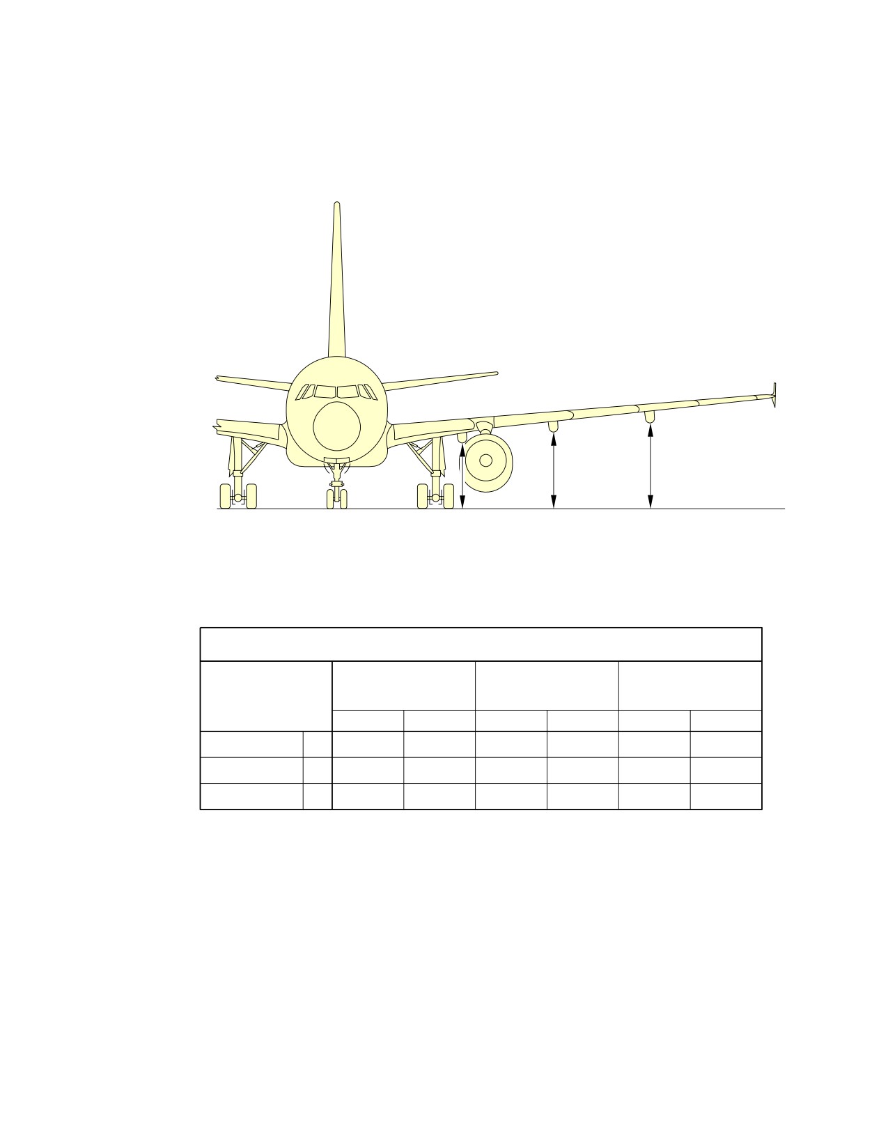
@A318
AIRCRAFT CHARACTERISTICS - AIRPORT AND MAINTENANCE PLANNING
**ON A/C A318-100
A
B
C
FLAP TRACKS RETRACTED
A/C IN MAINTENANCE
MAXIMUM RAMP
MAXIMUM RAMP
CONFIGURATION
WEIGHT FWD CG
WEIGHT AFT CG
DESCRIPTION
MID CG
m
ft
m
ft
m
ft
FLAP TRACK 2
A
2.70
8.86
2.60
8.53
2.58
8.46
FLAP TRACK 3
B
3.10
10.17
3.00
9.84
2.97
9.74
FLAP TRACK 4
C
3.50
11.48
3.39
11.12
3.36
11.02
N_AC_020300_1_0070101_01_01
Ground Clearances
Flap Tracks - Retracted
FIGURE-2-3-0-991-007-A01
Page 5
May 01/16
2-3-0
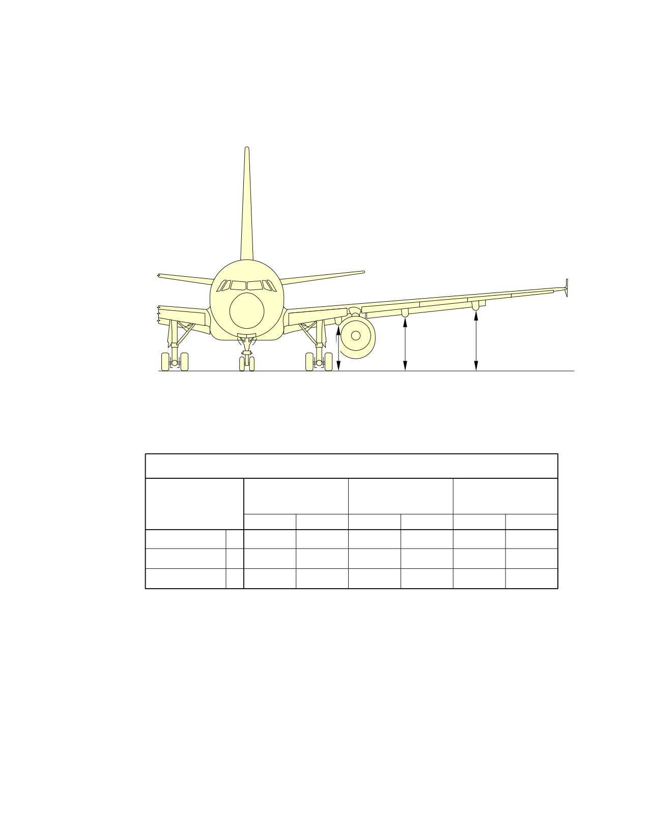
@A318
AIRCRAFT CHARACTERISTICS - AIRPORT AND MAINTENANCE PLANNING
**ON A/C A318-100
A
B
C
FLAP TRACKS 1+F
A/C IN MAINTENANCE
MAXIMUM RAMP
MAXIMUM RAMP
CONFIGURATION
WEIGHT FWD CG
WEIGHT AFT CG
DESCRIPTION
MID CG
m
ft
m
ft
m
ft
FLAP TRACK 2
A
1.95
6.40
1.85
6.07
1.83
6.00
FLAP TRACK 3
B
2.31
7.58
2.21
7.25
2.18
7.15
FLAP TRACK 4
C
2.89
9.48
2.78
9.12
2.75
9.02
N_AC_020300_1_0360101_01_00
Ground Clearances
Flap Tracks - 1 + F
FIGURE-2-3-0-991-036-A01
Page 6
May 01/16
2-3-0
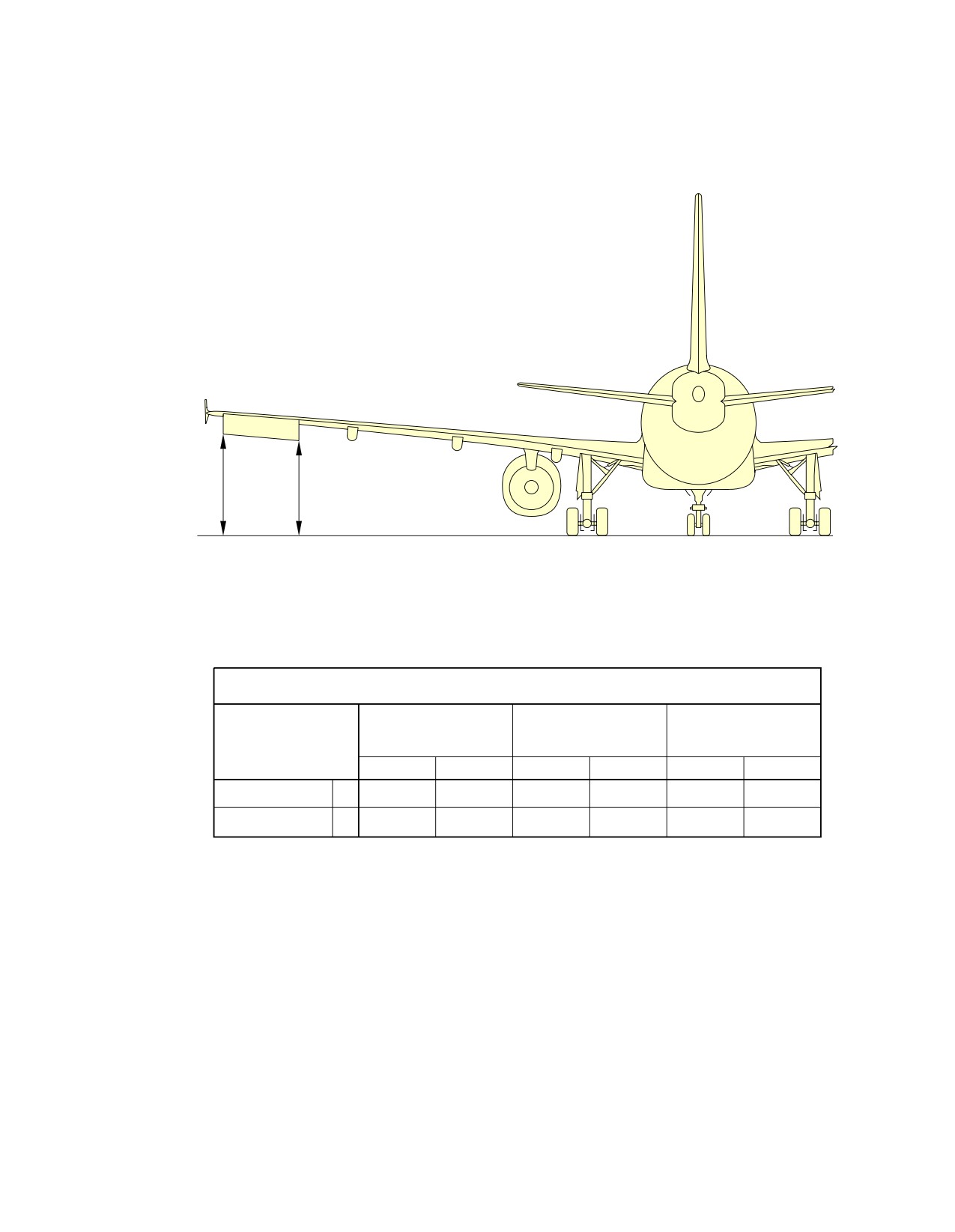
@A318
AIRCRAFT CHARACTERISTICS - AIRPORT AND MAINTENANCE PLANNING
**ON A/C A318-100
B
A
AILERON DOWN
A/C IN MAINTENANCE
MAXIMUM RAMP
MAXIMUM RAMP
CONFIGURATION
WEIGHT FWD CG
WEIGHT AFT CG
DESCRIPTION
MID CG
m
ft
m
ft
m
ft
AILERON INBD
A
3.84
12.60
3.78
12.40
3.74
12.27
AILERON OUTBD
B
4.19
13.75
4.13
13.55
4.07
13.35
N_AC_020300_1_0080101_01_01
Ground Clearances
Aileron Down
FIGURE-2-3-0-991-008-A01
Page 7
May 01/16
2-3-0
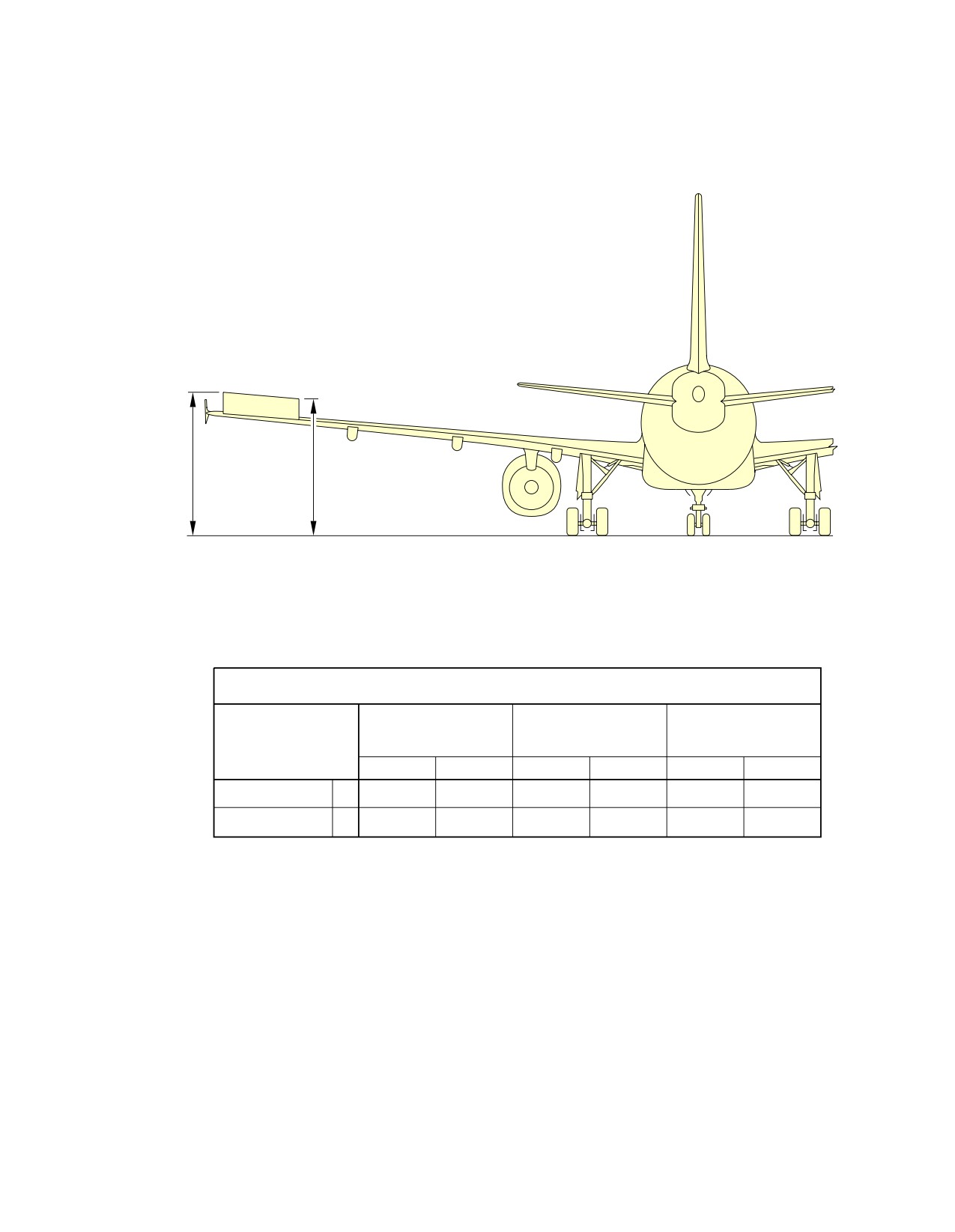
@A318
AIRCRAFT CHARACTERISTICS - AIRPORT AND MAINTENANCE PLANNING
**ON A/C A318-100
B
A
AILERON UP
A/C IN MAINTENANCE
MAXIMUM RAMP
MAXIMUM RAMP
CONFIGURATION
WEIGHT FWD CG
WEIGHT AFT CG
DESCRIPTION
MID CG
m
ft
m
ft
m
ft
AILERON INBD
A
4.37
14.34
4.31
14.14
4.45
14.60
AILERON OUTBD
B
4.57
14.99
4.51
14.80
4.26
13.98
N_AC_020300_1_0370101_01_00
Ground Clearances
Aileron Up
FIGURE-2-3-0-991-037-A01
Page 8
May 01/16
2-3-0
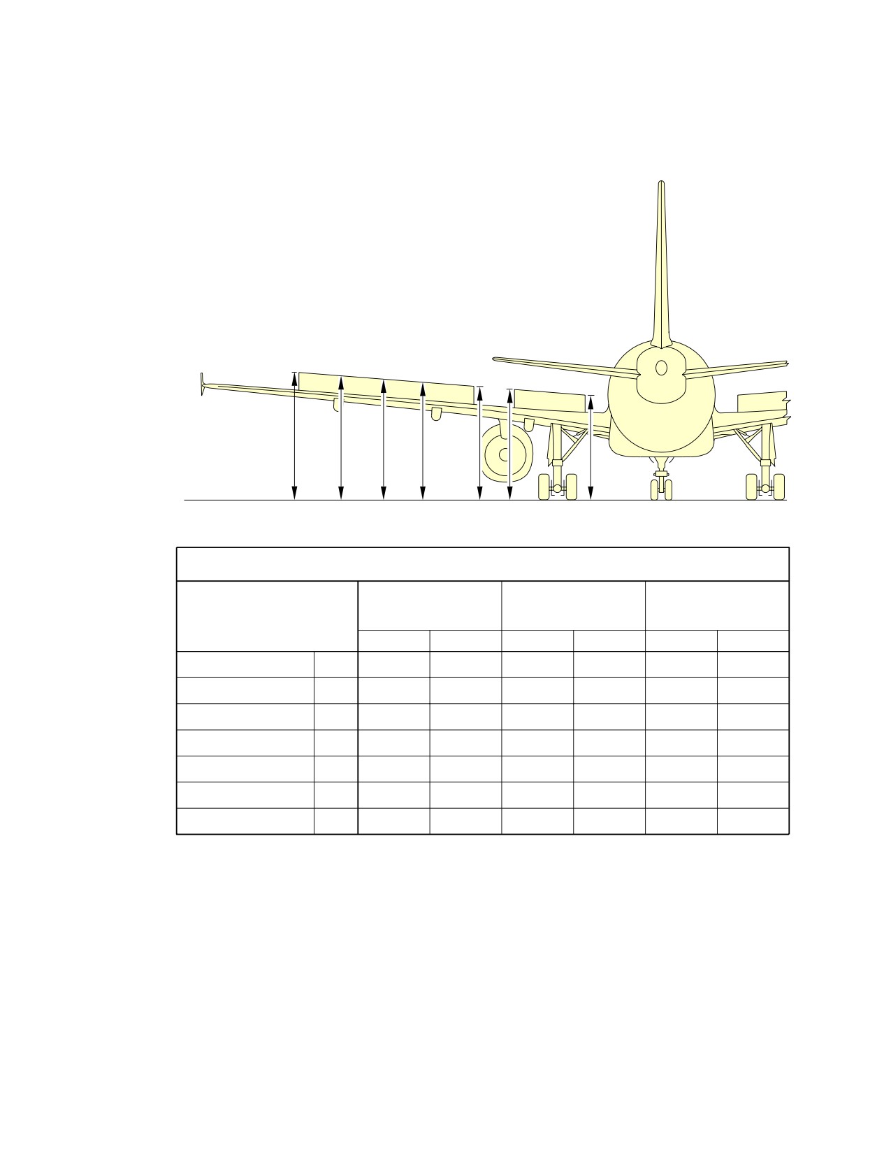
@A318
AIRCRAFT CHARACTERISTICS - AIRPORT AND MAINTENANCE PLANNING
**ON A/C A318-100
G
F
E
D
C B
A
SPOILERS EXTENDED
A/C IN MAINTENANCE
MAXIMUM RAMP
MAXIMUM RAMP
CONFIGURATION
WEIGHT FWD CG
WEIGHT AFT CG
DESCRIPTION
MID CG
m
ft
m
ft
m
ft
SPOILER 1 INBD
A
3.75
12.30
3.69
12.11
3.66
12.01
SPOILER 1 OUTBD
B
4.01
13.16
3.94
12.93
3.92
12.86
SPOILER 2 INBD
C
4.07
13.35
4.01
13.16
3.98
13.06
SPOILER 2/3
D
4.21
13.81
4.15
13.62
4.12
13.52
SPOILER 3/4
E
4.35
14.27
4.29
14.07
4.26
13.98
SPOILER 4/5
F
4.48
14.70
4.42
14.50
4.38
14.37
SPOILER 5 OUTBD
G
4.60
15.09
4.54
14.89
4.50
14.76
N_AC_020300_1_0090101_01_01
Ground Clearances
Spoilers - Extended
FIGURE-2-3-0-991-009-A01
Page 9
May 01/16
2-3-0
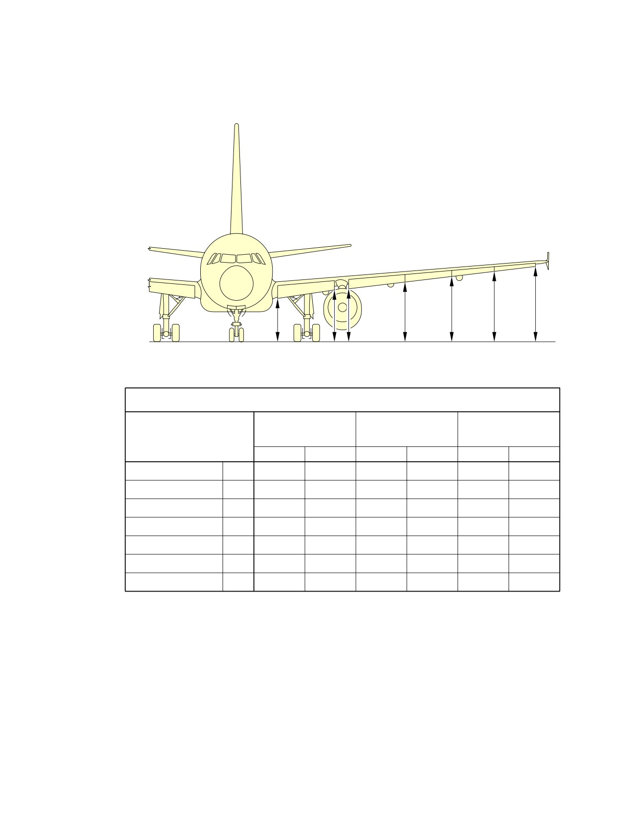
@A318
AIRCRAFT CHARACTERISTICS - AIRPORT AND MAINTENANCE PLANNING
**ON A/C A318-100
A
B C
D
E
F
G
LEADING EDGE SLATS EXTENDED
A/C IN MAINTENANCE
MAXIMUM RAMP
MAXIMUM RAMP
CONFIGURATION
WEIGHT FWD CG
WEIGHT AFT CG
DESCRIPTION
MID CG
m
ft
m
ft
m
ft
SLAT 1 INBD
A
2.54
8.33
2.48
8.14
2.50
8.20
SLAT 1 OUTBD
B
2.96
9.71
2.90
9.51
2.91
9.55
SLAT 2 INBD
C
3.05
10.01
2.99
9.81
2.99
9.81
SLAT 2/3
D
3.35
10.99
3.29
10.79
3.28
10.76
SLAT 3/4
E
3.61
11.84
3.55
11.65
3.53
11.58
SLAT 4/5
F
3.86
12.66
3.80
12.47
3.77
12.37
SLAT 5 OUTBD
G
4.10
13.45
4.04
13.25
4.00
13.12
N_AC_020300_1_0100101_01_01
Ground Clearances
Leading Edge Slats - Extended
FIGURE-2-3-0-991-010-A01
Page 10
May 01/16
2-3-0
@A318
AIRCRAFT CHARACTERISTICS - AIRPORT AND MAINTENANCE PLANNING
2-4-1
Interior Arrangements - Plan View
**ON A/C A318-100
Interior Arrangements - Plan View
1.
This section provides the typical interior configuration.
Page 1
May 01/16
2-4-1
@A318
AIRCRAFT CHARACTERISTICS - AIRPORT AND MAINTENANCE PLANNING
**ON A/C A318-100
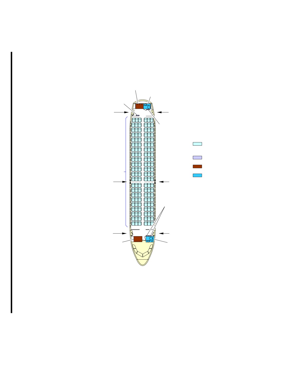
GALLEY
LAVATORY
ATTENDANT SEAT
AFT PASSENGER
AFT PASSENGER
/CREW DOOR
/CREW DOOR
ATTENDANT SEAT
PASSENGER SEATS (132 TOTAL)
ECONOMY CLASS 132 SEATS
(6 ABREAST − 29/30 in PITCH)
ATTENDANT SEATS 4
GALLEYS 2
ECONOMY
CLASS SEATS
LAVATORIES 2
EMERGENCY EXIT
EMERGENCY EXIT
ATTENDANT SEAT
FWD PASSENGER
FWD PASSENGER
/CREW DOOR
/CREW DOOR
GALLEY
LAVATORY
N_AC_020401_1_0010101_01_02
Interior Arrangements - Plan View
Typical Configuration - Single-Class, High Density
FIGURE-2-4-1-991-001-A01
Page 2
May 01/16
2-4-1
@A318
AIRCRAFT CHARACTERISTICS - AIRPORT AND MAINTENANCE PLANNING
**ON A/C A318-100
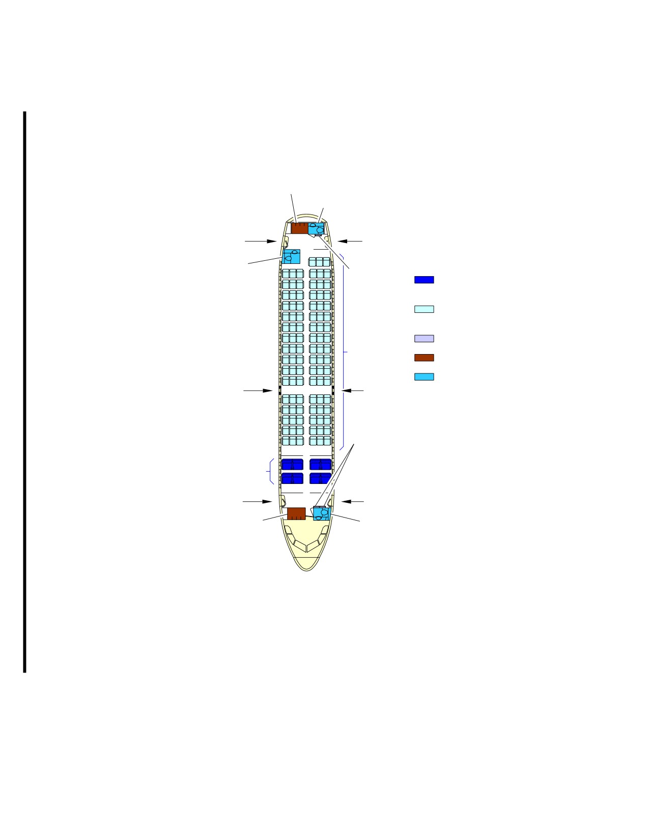
GALLEY
LAVATORY
AFT PASSENGER
AFT PASSENGER
/CREW DOOR
/CREW DOOR
LAVATORY
PASSENGER SEATS (107 TOTAL)
ATTENDANT SEAT
FIRST CLASS 8 SEATS
(4 ABREAST − 38 in PITCH)
ECONOMY CLASS 99 SEATS
(6 ABREAST − 32 in PITCH)
ATTENDANT SEATS 3
ECONOMY
CLASS SEATS
GALLEYS 2
LAVATORIES 3
EMERGENCY EXIT
EMERGENCY EXIT
ATTENDANT SEAT
FIRST
CLASS SEATS
FWD PASSENGER
FWD PASSENGER
/CREW DOOR
/CREW DOOR
GALLEY
LAVATORY
N_AC_020401_1_0070101_01_01
Interior Arrangements - Plan View
Typical Configuration - Two-Class
FIGURE-2-4-1-991-007-A01
Page 3
May 01/16
2-4-1
@A318
AIRCRAFT CHARACTERISTICS - AIRPORT AND MAINTENANCE PLANNING
2-5-0
Interior Arrangements - Cross Section
**ON A/C A318-100
Interior Arrangements - Cross Section
1.
This section provides the typical configuration.
Page 1
May 01/16
2-5-0
@A318
AIRCRAFT CHARACTERISTICS - AIRPORT AND MAINTENANCE PLANNING
**ON A/C A318-100
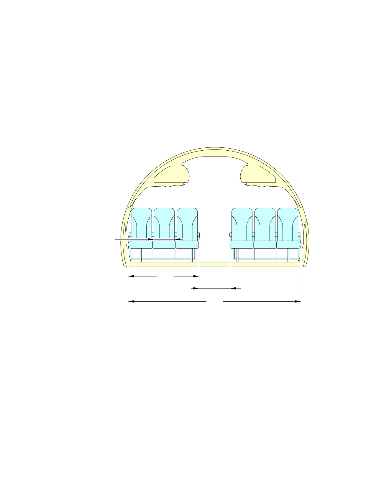
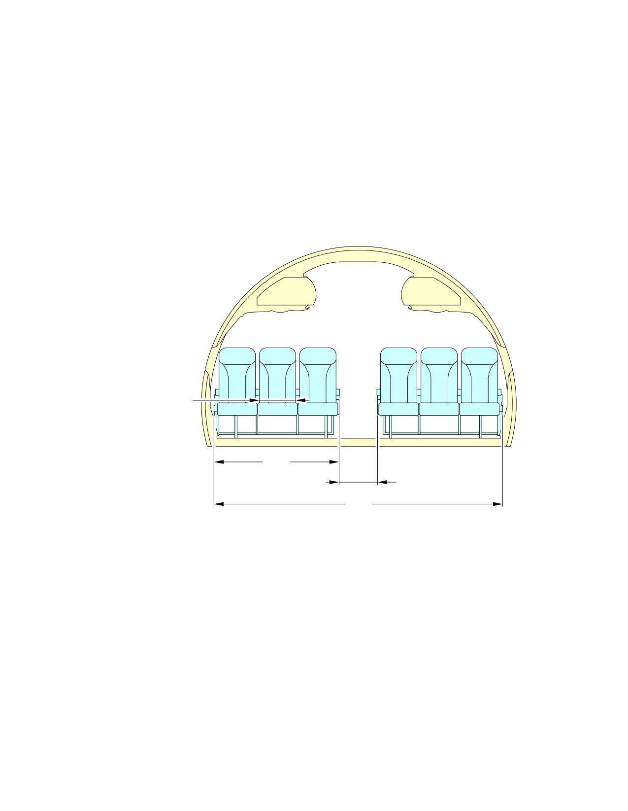
6 ABREAST−WIDER AISLE
0.43 m
(17 in)
1.50 m
(59 in)
0.64 m
(25 in)
3.63 m
(143 in)
N_AC_020500_1_0050101_01_01
Interior Arrangements - Cross Section
Economy Class, 6 Abreast - Wider Aisle (Sheet 1 of 2)
FIGURE-2-5-0-991-005-A01
Page 2
May 01/16
2-5-0
@A318
AIRCRAFT CHARACTERISTICS - AIRPORT AND MAINTENANCE PLANNING
**ON A/C A318-100
6 ABREAST−WIDER SEAT
0.46 m
(18 in)
1.58 m
(62 in)
0.48 m
(19 in)
3.63 m
(143 in)
N_AC_020500_1_0050102_01_03
Interior Arrangements - Cross Section
Economy Class, 6 Abreast - Wider Seat (Sheet 2 of 2)
FIGURE-2-5-0-991-005-A01
Page 3
May 01/16
2-5-0
@A318
AIRCRAFT CHARACTERISTICS - AIRPORT AND MAINTENANCE PLANNING
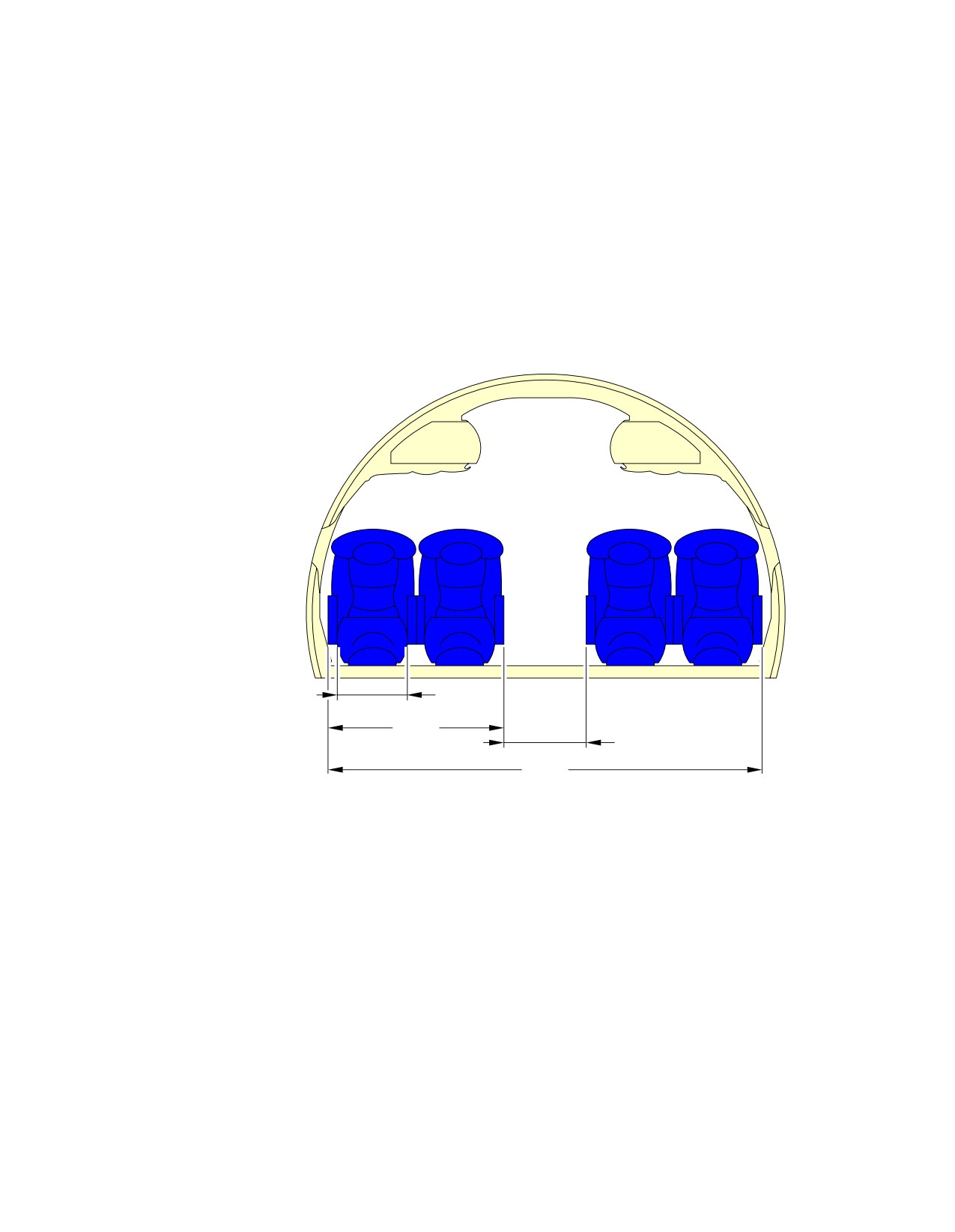
**ON A/C A318-100
4 ABREAST−FIRST CLASS
0.57 m
(22.6 in)
1.45 m
(57 in)
0.69 m
(27 in)
3.58 m
(141 in)
N_AC_020500_1_0060101_01_01
Interior Arrangements - Cross Section
First-Class
FIGURE-2-5-0-991-006-A01
Page 4
May 01/16
2-5-0
@A318
AIRCRAFT CHARACTERISTICS - AIRPORT AND MAINTENANCE PLANNING
2-6-0
Cargo Compartments
**ON A/C A318-100
Cargo Compartments
1.
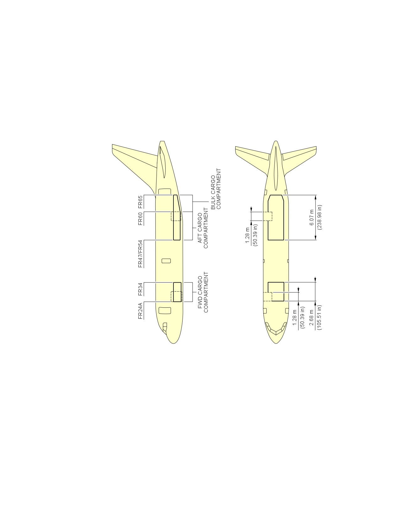
This section gives the cargo compartments locations, dimensions and loading combinations.
Page 1
May 01/16
2-6-0
@A318
AIRCRAFT CHARACTERISTICS - AIRPORT AND MAINTENANCE PLANNING
**ON A/C A318-100
N_AC_020600_1_0010101_01_00
Cargo Compartments
Locations and Dimensions
FIGURE-2-6-0-991-001-A01
Page 2
May 01/16
2-6-0
@A318
AIRCRAFT CHARACTERISTICS - AIRPORT AND MAINTENANCE PLANNING
2-7-0
Door Clearances and Location
**ON A/C A318-100
Door Clearances
1.
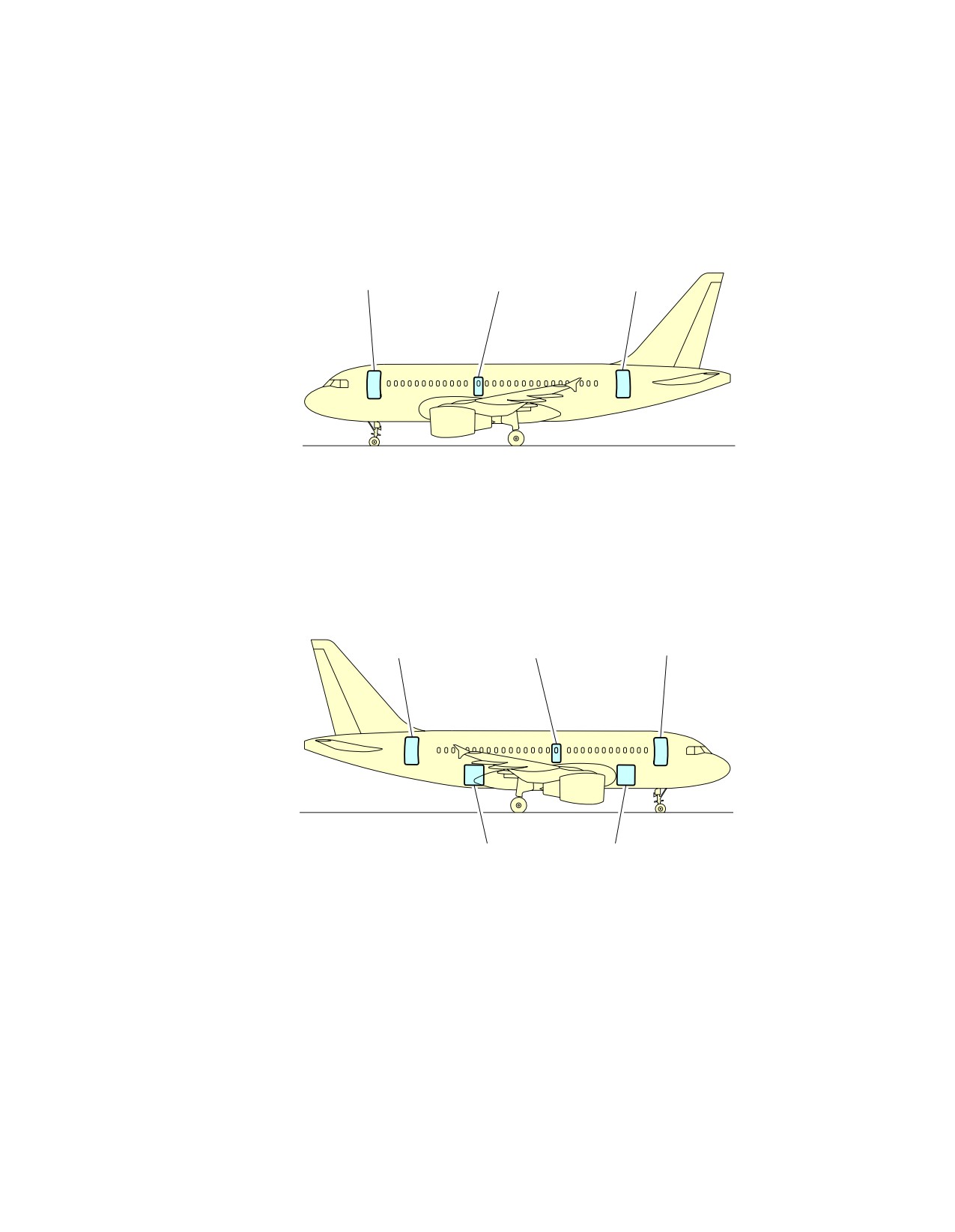
This section provides door identification and location.
NOTE : Dimensions of the ground clearances are approximate and will vary with tire type, weight
and balance and other special conditions.
Page 1
May 01/16
2-7-0
@A318
AIRCRAFT CHARACTERISTICS - AIRPORT AND MAINTENANCE PLANNING
**ON A/C A318-100
FWD
OVERWING
AFT
PASSENGER/CREW
EMERGENCY
PASSENGER/CREW
DOOR (LH)
EXIT DOOR (LH)
DOOR (LH)
AFT
OVERWING
FWD
PASSENGER/CREW
EMERGENCY
PASSENGER/CREW
DOOR (RH)
EXIT DOOR (RH)
DOOR (RH)
AFT CARGO
FWD CARGO
COMPARTMENT
COMPARTMENT
DOOR
DOOR
N_AC_020700_1_0010101_01_01
Door Identification and Location
Door Identification (Sheet 1 of 2)
FIGURE-2-7-0-991-001-A01
Page 2
May 01/16
2-7-0
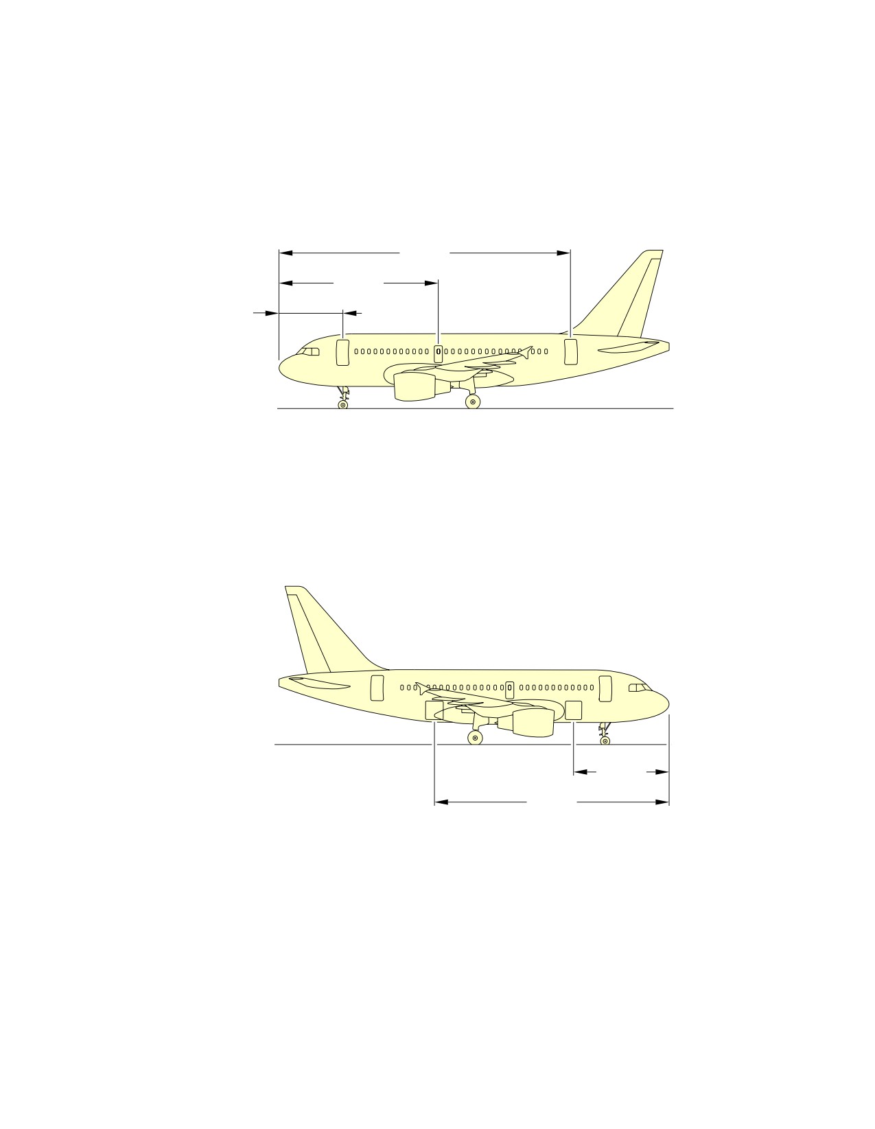
@A318
AIRCRAFT CHARACTERISTICS - AIRPORT AND MAINTENANCE PLANNING
**ON A/C A318-100
23.41 m
(76.80 ft)
12.89 m
(42.29 ft)
5.04 m
(16.54 ft)
7.89 m
(25.89 ft)
18.97 m
(62.24 ft)
N_AC_020700_1_0010102_01_01
Door Identification and Location
Door Location (Sheet 2 of 2)
FIGURE-2-7-0-991-001-A01
Page 3
May 01/16
2-7-0
@A318
AIRCRAFT CHARACTERISTICS - AIRPORT AND MAINTENANCE PLANNING
**ON A/C A318-100
1.80 m
(5.91 ft)
0.48 m
0.81 m
(1.57 ft)
(2.66 ft)
C
L
2.54 m
(8.33 ft)
CRITICAL CLEARANCE
LIMIT
0.61 m
5.02 m
(2.00 ft)
(16.47 ft)
2.38 m
(7.81 ft)
1.85 m
(6.07 ft)
C
C
L
L
SEE
0.03 m
CHAPTER
(0.10 ft)
2−3
N_AC_020700_1_0050101_01_00
Doors Clearances
Forward Passenger/Crew Doors
FIGURE-2-7-0-991-005-A01
Page 4
May 01/16
2-7-0
@A318
AIRCRAFT CHARACTERISTICS - AIRPORT AND MAINTENANCE PLANNING
**ON A/C A318-100
C
L
FWD
12.89 m
(FROM NOSE)
(42.29 ft)
0.56 m
(1.84 ft)
A
B
0.47 m
(1.54 ft)
C
L
SEE
SECTION
0.20 m
2−3
(0.66 ft)
A
B
1.23 m
(4.04 ft)
0.90 m
(2.95 ft)
0.12 m
(0.39 ft)
0.50 m
(1.64 ft)
(TOP OF FLOOR)
B B
(FRAME 47)
A A
NOTE:
ESCAPE SLIDE COMPARTMENT DOOR OPENS ON WING UPPER SURFACE.
N_AC_020700_1_0060101_01_00
Doors Clearances
Emergency Exits
FIGURE-2-7-0-991-006-A01
Page 5
May 01/16
2-7-0
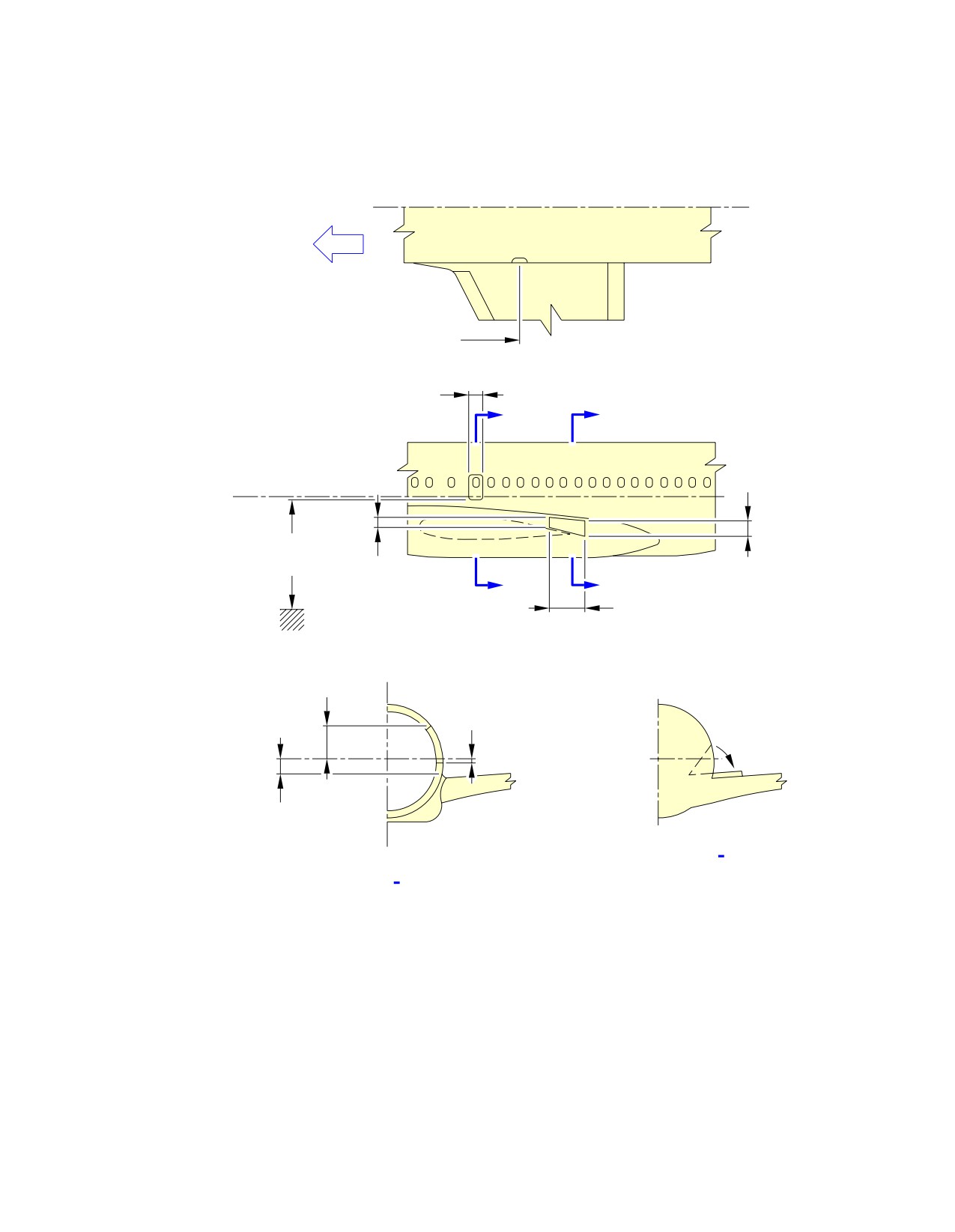
@A318
AIRCRAFT CHARACTERISTICS - AIRPORT AND MAINTENANCE PLANNING
**ON A/C A318-100
1.79 m
(5.87 ft)
0.81 m
(2.66 ft)
FWD
A
CRITICAL
CLEARANCE
0.58 m
LIMIT
(1.90 ft)
A
2.44 m
(8.01 ft)
(FROM NOSE) 23.52 m
(77.17 ft)
1.85 m
SEE
(6.07 ft)
CHAPTER
0.60 m
2−3
(1.97 ft)
0.03 m
(0.10 ft)
A A
N_AC_020700_1_0070101_01_00
Doors Clearances
Aft Passenger/Crew Doors
FIGURE-2-7-0-991-007-A01
Page 6
May 01/16
2-7-0
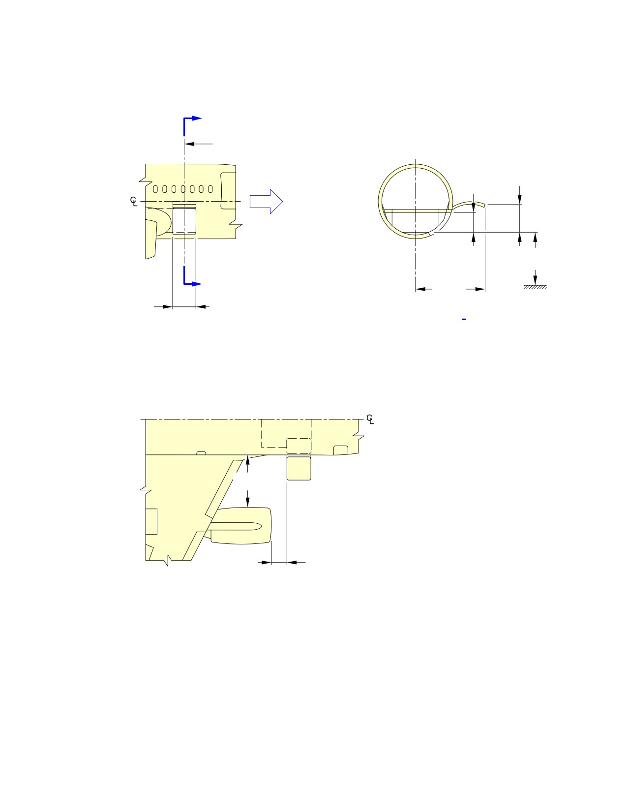
@A318
AIRCRAFT CHARACTERISTICS - AIRPORT AND MAINTENANCE PLANNING
**ON A/C A318-100
A
7.89 m
(FROM NOSE)
(25.89 ft)
1.50 m
1.24 m
(4.92 ft)
(4.07 ft)
FWD
SEE
CHAPTER
2−3
A
3.95 m
(12.96 ft)
1.33 m
(4.36 ft)
A A
2.90 m
(9.51 ft)
CFM56 = 0.26 m (0.85 ft)
PW6000 = 0.57 m (1.87 ft)
N_AC_020700_1_0080101_01_00
Doors Clearances
Forward Cargo Compartment Door
FIGURE-2-7-0-991-008-A01
Page 7
May 01/16
2-7-0
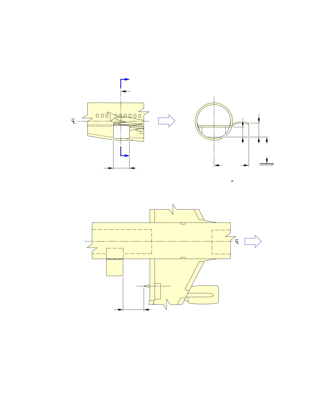
@A318
AIRCRAFT CHARACTERISTICS - AIRPORT AND MAINTENANCE PLANNING
**ON A/C A318-100
A
19.96 m
(FROM NOSE)
(65.49 ft)
1.43 m
1.23 m
(4.69 ft)
(4.04 ft)
FWD
SEE
CHAPTER
2−3
A
3.95 m
1.33 m
(12.96 ft)
(4.36 ft)
A A
FWD
1.00 m
(3.28 ft)
N_AC_020700_1_0090101_01_00
Doors Clearances
Aft Cargo Compartment Door
FIGURE-2-7-0-991-009-A01
Page 8
May 01/16
2-7-0
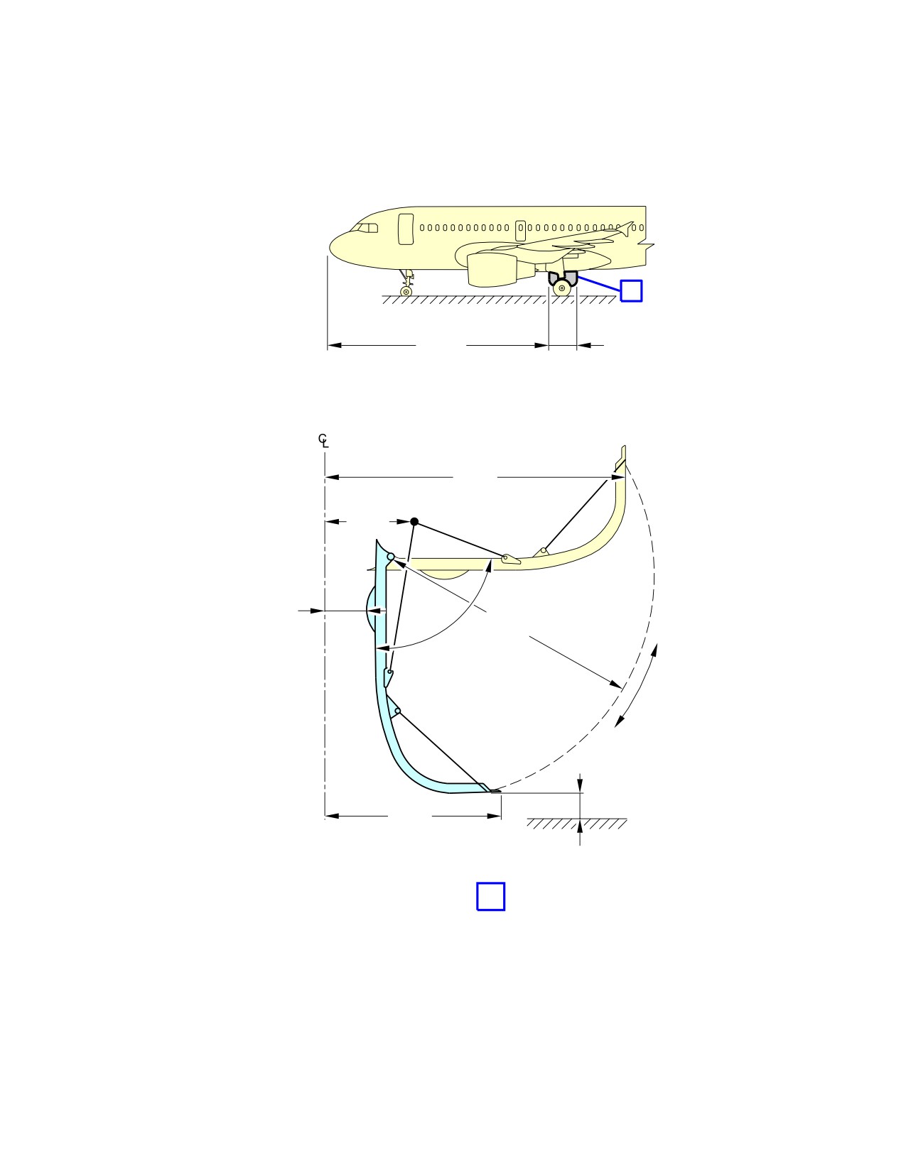
@A318
AIRCRAFT CHARACTERISTICS - AIRPORT AND MAINTENANCE PLANNING
**ON A/C A318-100
A
13.97 m
1.83 m
(45.83 ft)
(6.00 ft)
AIRCRAFT
1.94 m
(6.36 ft)
0.49 m
(1.61 ft)
0.21 m
(0.69 ft)
1.76 m
84°
(5.77 ft)
1.23 m
(4.04 ft)
GROUND LINE
0.14 m
(0.46 ft)
A
NOTE:
VALUE OF CG: 25% RC.
N_AC_020700_1_0100101_01_00
Doors Clearances
Main Landing Gear Doors
FIGURE-2-7-0-991-010-A01
Page 9
May 01/16
2-7-0
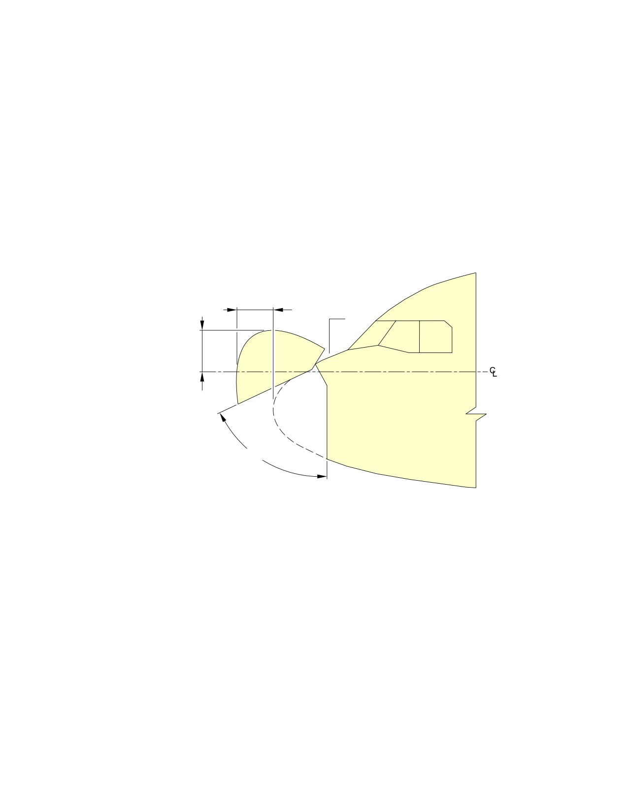
@A318
AIRCRAFT CHARACTERISTICS - AIRPORT AND MAINTENANCE PLANNING
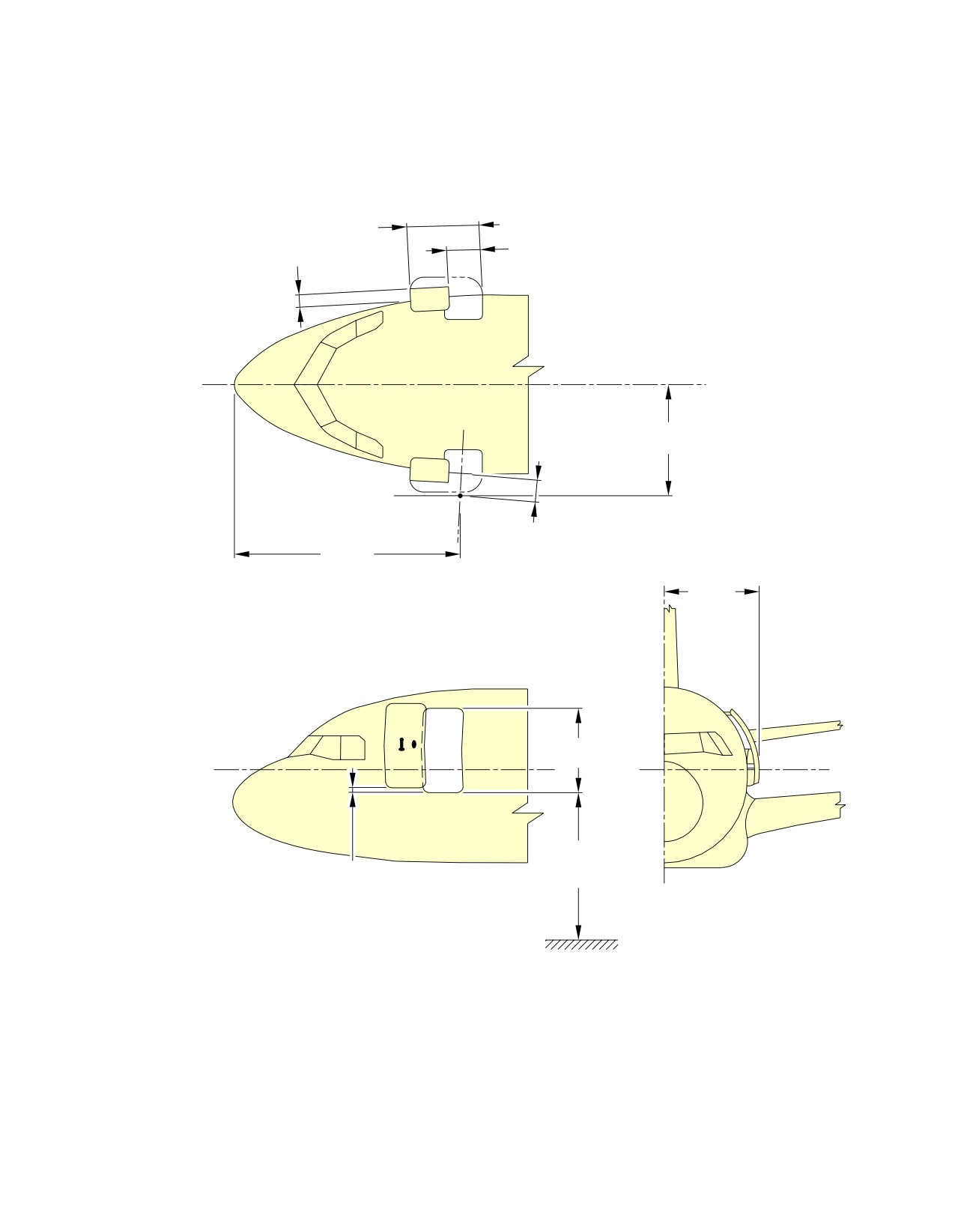
**ON A/C A318-100
0.63 m
(2.07 ft)
FR1
1.54 m
(5.05 ft)
65°
N_AC_020700_1_0110101_01_00
Doors Clearances
Radome
FIGURE-2-7-0-991-011-A01
Page 10
May 01/16
2-7-0
@A318
AIRCRAFT CHARACTERISTICS - AIRPORT AND MAINTENANCE PLANNING
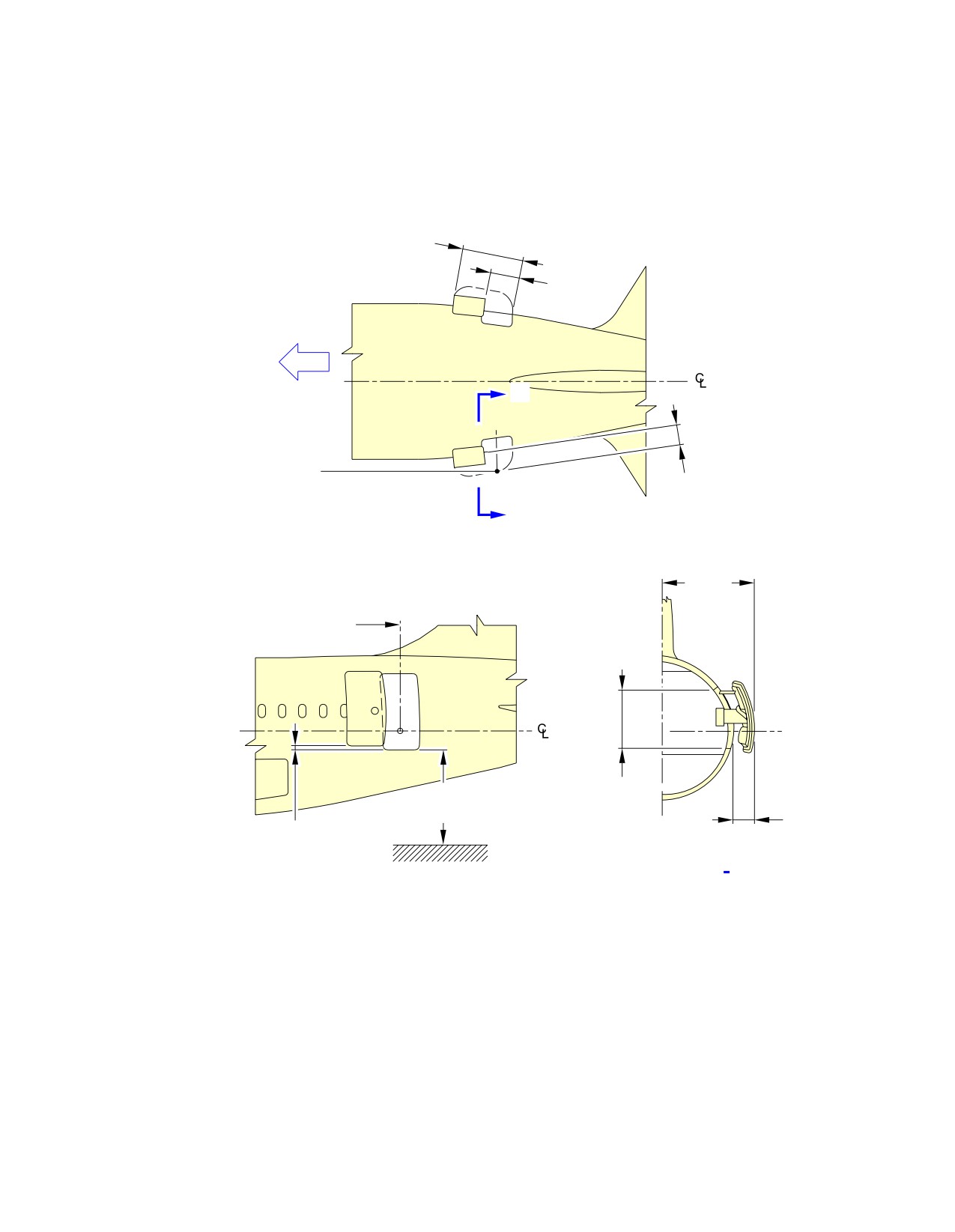
**ON A/C A318-100
FR80
FR84
3.86 m
3.23 m
(12.66 ft)
(10.60 ft)
1.50 m
(4.92 ft)
1.40 m
NOTE:
(4.59 ft)
VALUE OF CG: 25% RC.
N_AC_020700_1_0120101_01_00
Doors Clearances
APU and Nose Landing Gear Doors
FIGURE-2-7-0-991-012-A01
Page 11
May 01/16
2-7-0
@A318
AIRCRAFT CHARACTERISTICS - AIRPORT AND MAINTENANCE PLANNING
2-8-0
Escape Slides
**ON A/C A318-100
Escape Slides
1.
General
This section provides location of cabin escape facilities and related clearances.
2.
Location
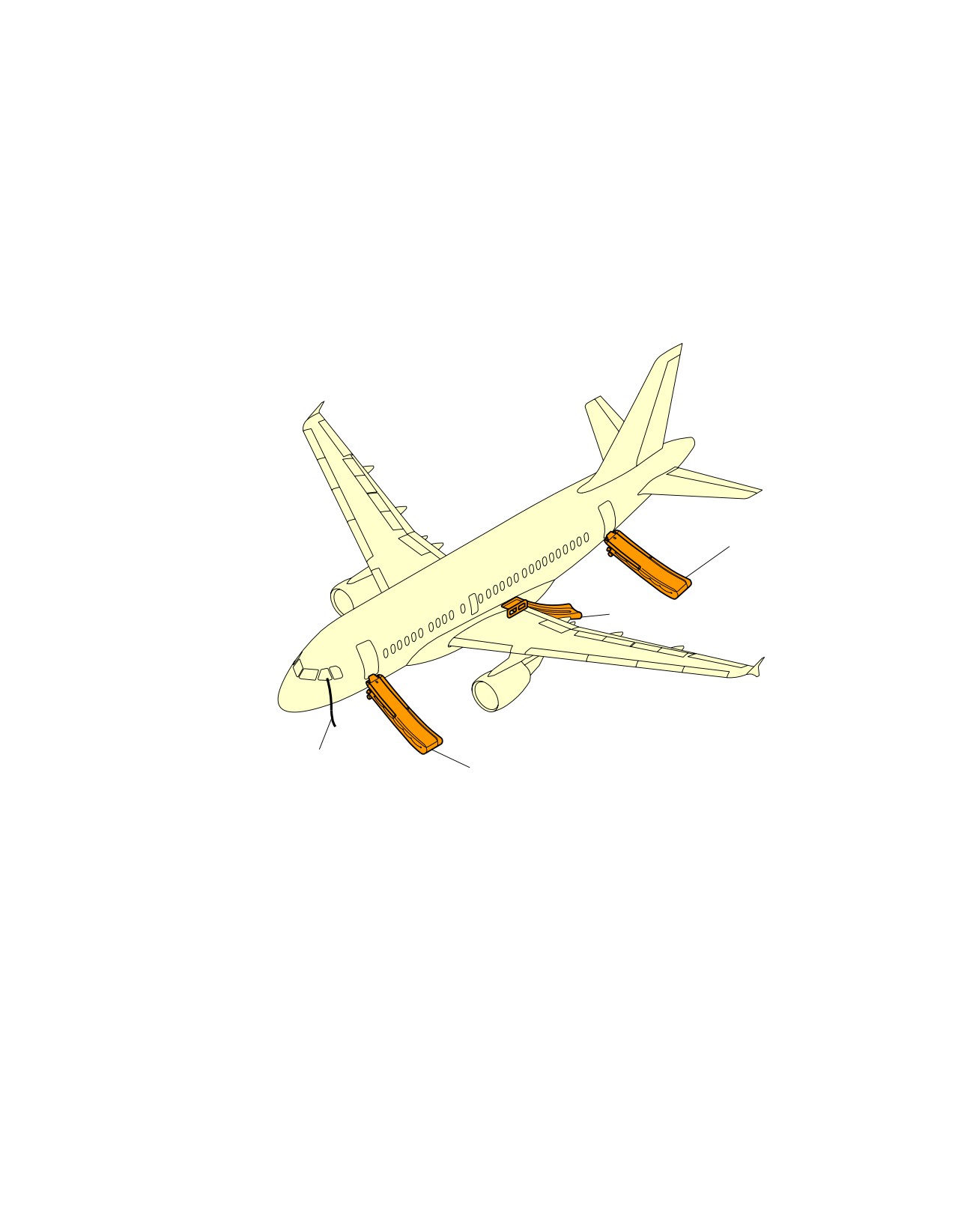
Escape facilities are provided at the following locations:
-
One escape slide at each passenger/crew door (total four)
-
One escape slide for each emergency exit door (total two). Dual lane offwing escape slides are
installed above the wings in the left and right wing-to-fuselage fairings for off-the-wing
evacuation.
Page 1
May 01/16
2-8-0
@A318
AIRCRAFT CHARACTERISTICS - AIRPORT AND MAINTENANCE PLANNING
**ON A/C A318-100
AFT CABIN ESCAPE SLIDE
OFF WING ESCAPE SLIDE
COCKPIT ESCAPE
FWD CABIN ESCAPE SLIDE
ROPE
NOTE:
LH SHOWN, RH SYMMETRICAL.
N_AC_020800_1_0010101_01_03
Escape Slides
Location
FIGURE-2-8-0-991-001-A01
Page 2
May 01/16
2-8-0
@A318
AIRCRAFT CHARACTERISTICS - AIRPORT AND MAINTENANCE PLANNING
**ON A/C A318-100
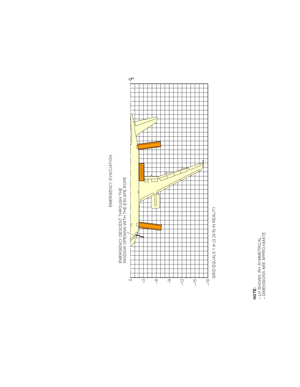
N_AC_020800_1_0020101_01_02
Escape Slides
Dimensions
FIGURE-2-8-0-991-002-A01
Page 3
May 01/16
2-8-0
@A318
AIRCRAFT CHARACTERISTICS - AIRPORT AND MAINTENANCE PLANNING
2-9-0
Landing Gear
**ON A/C A318-100
Landing Gear
1.
General
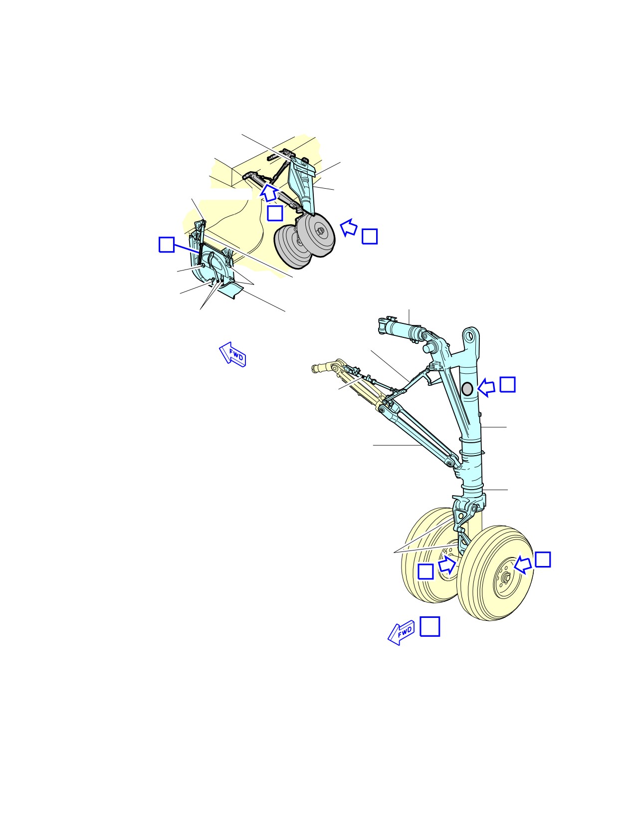
The landing gear is of the conventional retractable tricycle type comprising:
-
Two main gears with twin-wheel,
-
A twin-wheel nose gear.
The main landing gears are located under the wing and retract sideways towards the fuselage
centerline.
The nose landing gear retracts forward into a fuselage compartment located between FR9 and FR20.
The landing gears and landing gear doors are operated and controlled electrically and hydraulically.
In abnormal operation, the landing gear can be extended by gravity.
For landing gear footprint and tire size, refer to 07-02-00.
2.
Main Landing Gear
A. Twin-Wheel
Each of the two main landing gear assemblies consists of a conventional two-wheel direct type
with an integral shock absorber supported in the fore and aft directions by a fixed drag strut
and laterally by a folding strut mechanically locked when in the DOWN position.
3.
Nose Landing Gear
The nose landing gear consists of a leg with a built-in shock absorber strut, carrying twin wheels with
adequate shimmy damping and a folding strut mechanically locked when in the DOWN position.
4.
Nose Wheel Steering
Steering is controlled by two hand wheels in the cockpit. For steering angle controlled by the hand
wheels, refer to AMM 32-51-00.
For steering angle limitation, refer to AMM 09-10-00.
A steering disconnection box is installed on the nose landing gear to allow steering deactivation for
towing purposes.
5.
Landing Gear Servicing Points
A. General
Filling of the landing-gear shock absorbers is done through MIL-PRF-6164 standard valves.
Page 1
May 01/16
2-9-0
@A318
AIRCRAFT CHARACTERISTICS - AIRPORT AND MAINTENANCE PLANNING
Charging of the landing-gear shock absorbers is accomplished with nitrogen through MIL-
PRF-6164 standard valves.
B. Charging Pressure
For charging of the landing-gear shock absorbers, refer to AMM 12-14-32.
6.
Braking
A. General
The four main wheels are equipped with carbon multidisc brakes.
The braking system is electrically controlled and hydraulically operated.
The braking system has four braking modes plus autobrake and anti-skid systems:
-
Normal braking with anti-skid capability,
-
Alternative braking with anti-skid capability,
-
Alternative braking without anti-skid capability,
-
Parking brake with full pressure application capability only.
B. In-Flight Wheel Braking
The main gear wheels are braked automatically before the wheels enter the wheel bay.
The nose gear wheels are stopped by the wheels contacting a rubbing strip (the brake band)
when the gear is in the retracted position.
Page 2
May 01/16
2-9-0
@A318
AIRCRAFT CHARACTERISTICS - AIRPORT AND MAINTENANCE PLANNING
**ON A/C A318-100
HINGED FAIRING
(MECHANICALLY OPERATED)
HINGED
FAIRING
FIXED
DOOR ACTUATING CYLINDER
FAIRING
B
A
C
ADJUSTABLE
RAMP
PROXIMITY SENSORS
STEPS
UPLOCK
ACTUATING
ROLLER
CYLINDER
FIXED
MAIN DOOR
RAMPS
(HYDRAULICALLY OPERATED)
LOCK STAY
UNLOCK
E
ACTUATOR
MAIN
FITTING
SIDE STAY
SHOCK
ABSORBER
TORQUE
LINK
D
D
A
NOTE: MAIN DOOR SHOWN OPEN IN GROUND MAINTENANCE POSITION.
N_AC_020900_1_0020101_01_00
Landing Gear
Main Landing Gear - Twin-Wheel (Sheet 1 of 2)
FIGURE-2-9-0-991-002-A01
Page 3
May 01/16
2-9-0
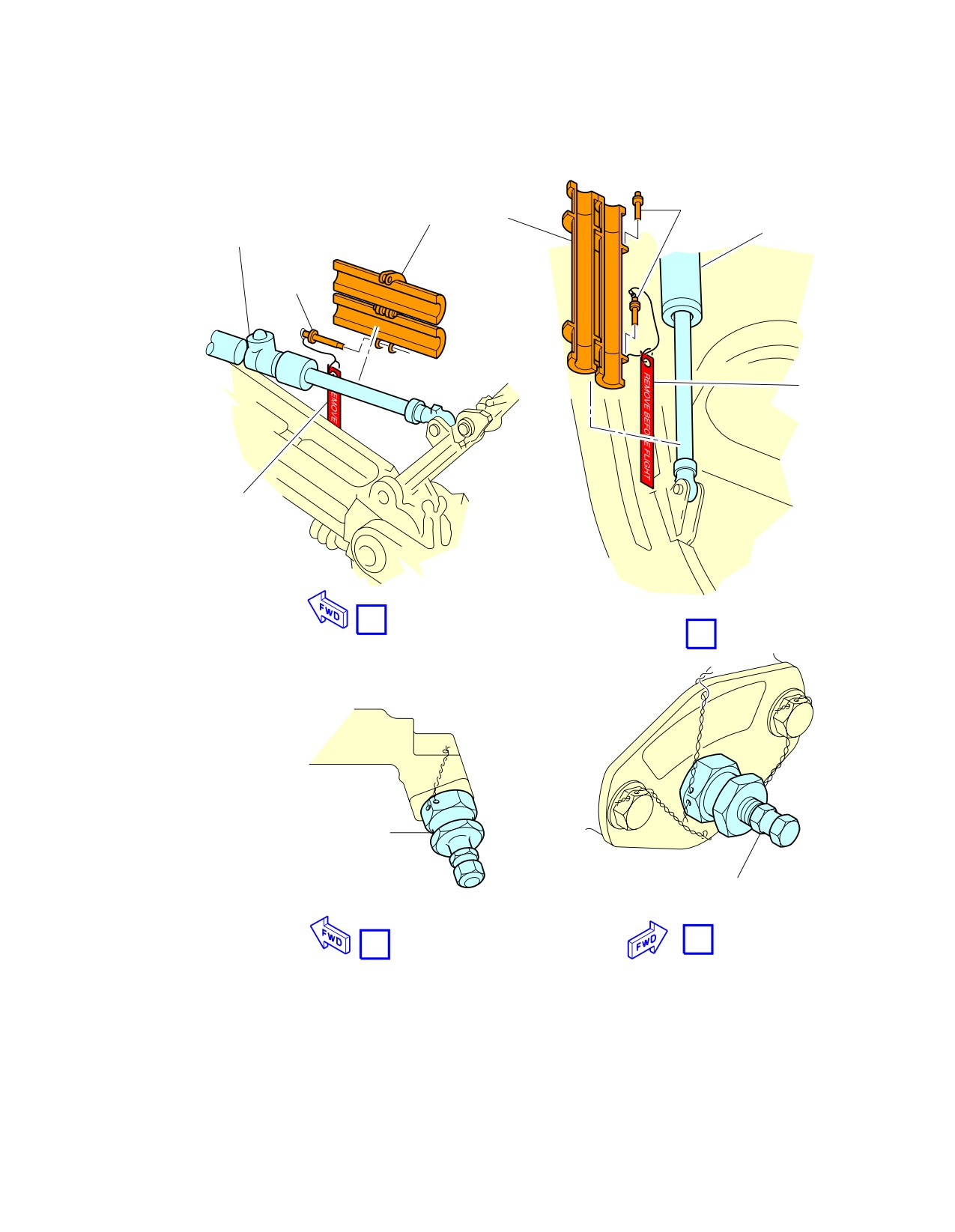
@A318
AIRCRAFT CHARACTERISTICS - AIRPORT AND MAINTENANCE PLANNING
**ON A/C A318-100
DOOR
LOCKSTAY
LOCKING
GROUND LOCK SLEEVE
ACTUATING
ACTUATING
PIN
CYLINDER
CYLINDER
LOCKING
PIN
FLAG
FLAG
B
C
BOTTOM FILLING AND
CHARGING CONNECTION
TOP FILLING AND CHARGING
CONNECTION
E
D
EXAMPLE
N_AC_020900_1_0020102_01_01
Landing Gear
Main Landing Gear - Twin-Wheel (Sheet 2 of 2)
FIGURE-2-9-0-991-002-A01
Page 4
May 01/16
2-9-0
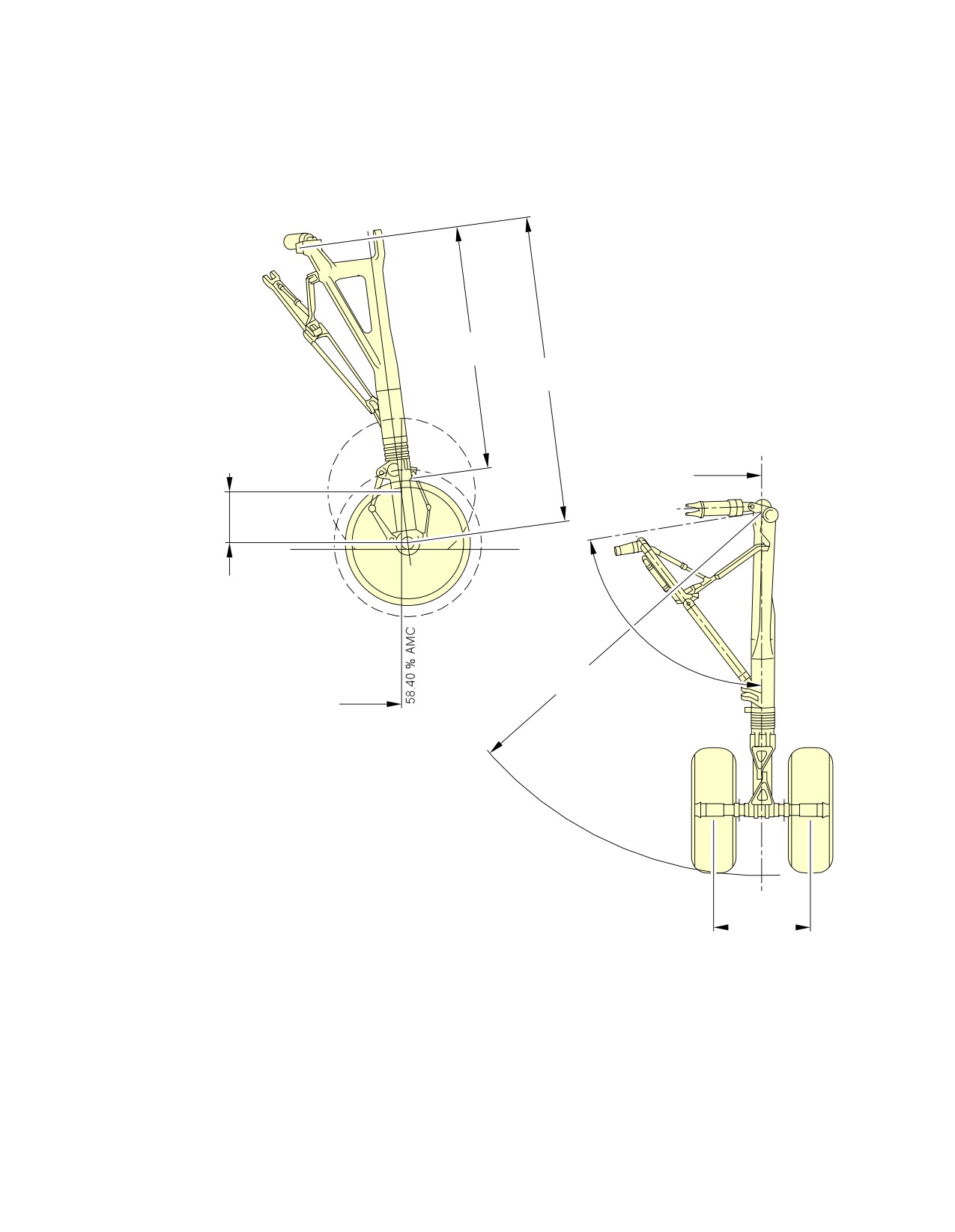
@A318
AIRCRAFT CHARACTERISTICS - AIRPORT AND MAINTENANCE PLANNING
**ON A/C A318-100
2 265 mm
(89.17 in)
2 868.70 mm
(112.94 in)
3 795 mm
Y=
COMPRESSED
(149.41 in)
EXTENDED
469.90 mm
(18.50 in)
3 453 mm
80°30
(135.94 in)
20 252.50 mm
RETRACTION
X=
(797.34 in)
ANGLE
927.10 mm
(36.50 in)
N_AC_020900_1_0030101_01_00
Landing Gear
Main Landing Gear Dimensions - Twin-Wheel
FIGURE-2-9-0-991-003-A01
Page 5
May 01/16
2-9-0
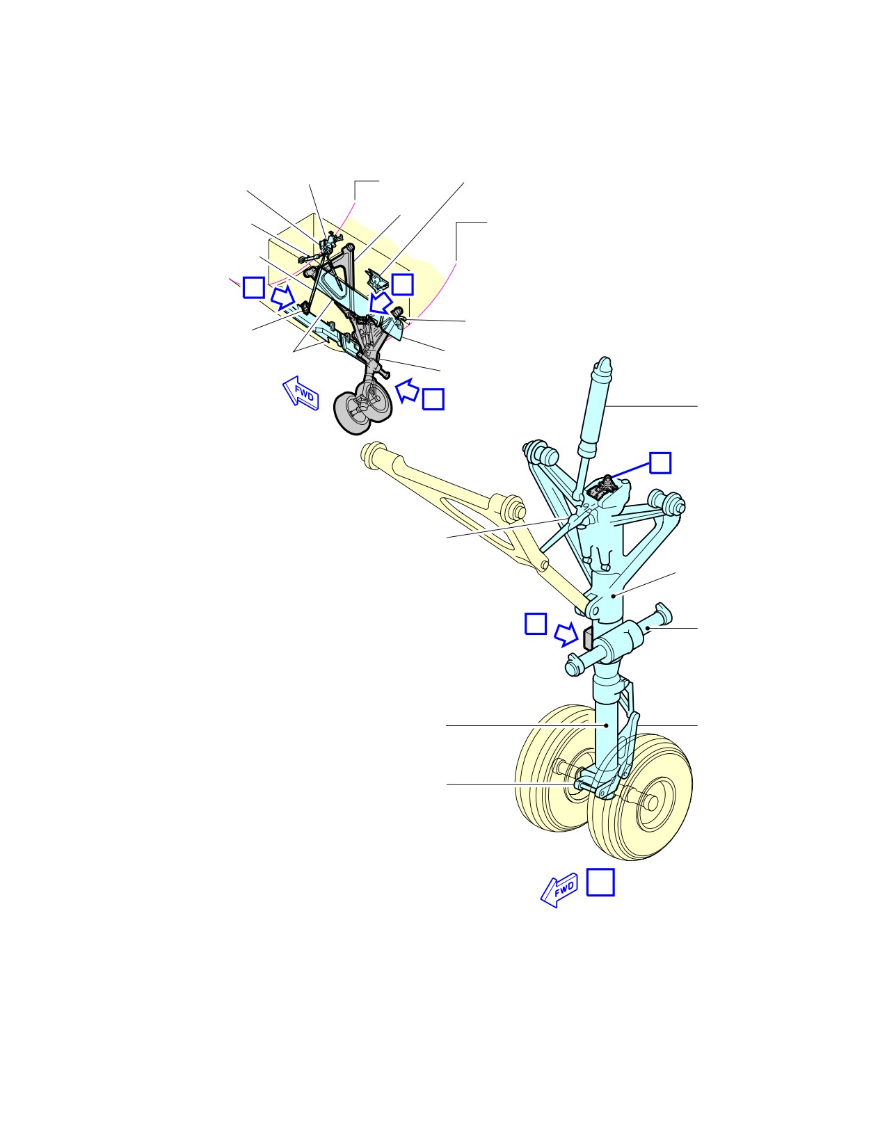
@A318
AIRCRAFT CHARACTERISTICS - AIRPORT AND MAINTENANCE PLANNING
**ON A/C A318-100
DOOR UPLOCK
BELL
FR9
ASSEMBLY
GEAR UPLOCK
CRANK
DRAG STRUT
ASSEMBLY
DOOR
ASSEMBLY
FR20
ACTUATING
CYLINDER
CONTROL ROD
B
C
ROTATING ROD
FITTING
ASSEMBLY
FWD DOORS
AFT DOORS
LEG DOOR
A
ACTUATING
CYLINDER
D
DOWNLOCK
PROXIMITY
DETECTORS
NOSE WHEEL
STEERING
SERVO CONTROL
STEERING
E
ACTUATING
CYLINDER
SHOCK
TORQUE
ABSORBER
LINK
TOWING
FITTING
A
N_AC_020900_1_0040101_01_00
Landing Gear
Nose Landing Gear (Sheet 1 of 2)
FIGURE-2-9-0-991-004-A01
Page 6
May 01/16
2-9-0
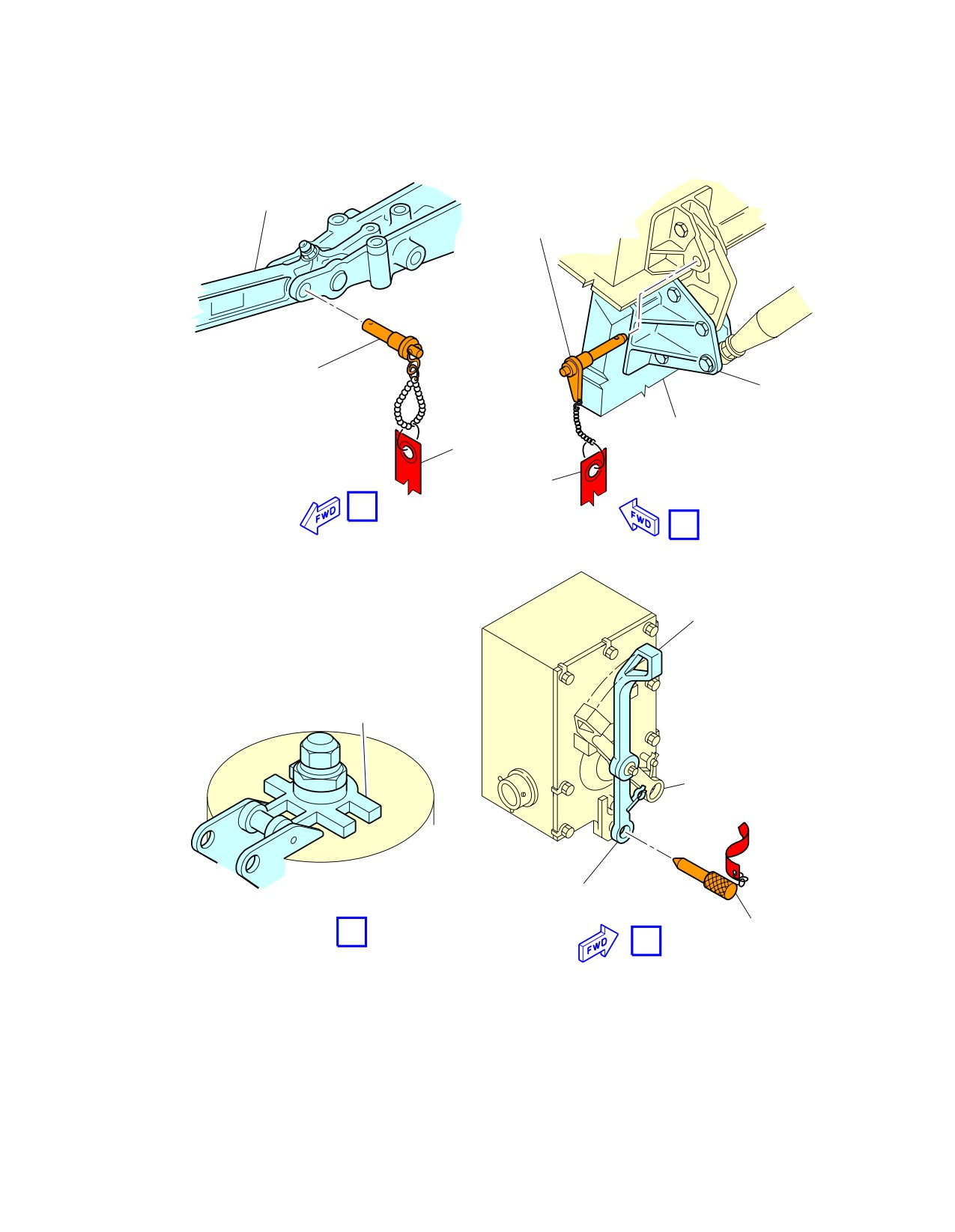
@A318
AIRCRAFT CHARACTERISTICS - AIRPORT AND MAINTENANCE PLANNING
**ON A/C A318-100
LOCKSTAY
NLG DOOR
SAFETY PIN
DOWNLOCK
SAFETY PIN
DOOR HINGE
NLG DOOR
FLAG
FLAG
B
C
RH SHOWN
LH SYMMETRICAL
TOWING LEVER
FILLING AND CHARGING
CONNECTION
NORMAL POSITION
(NOSE WHEEL STEERING
OPERATIONAL)
TOWING POSITION
(NOSE WHEEL STEERING DEACTIVATED)
SAFETY PIN
D
E
(TOWING POSITION)
N_AC_020900_1_0040102_01_01
Landing Gear
Nose Landing Gear (Sheet 2 of 2)
FIGURE-2-9-0-991-004-A01
Page 7
May 01/16
2-9-0
@A318
AIRCRAFT CHARACTERISTICS - AIRPORT AND MAINTENANCE PLANNING
**ON A/C A318-100
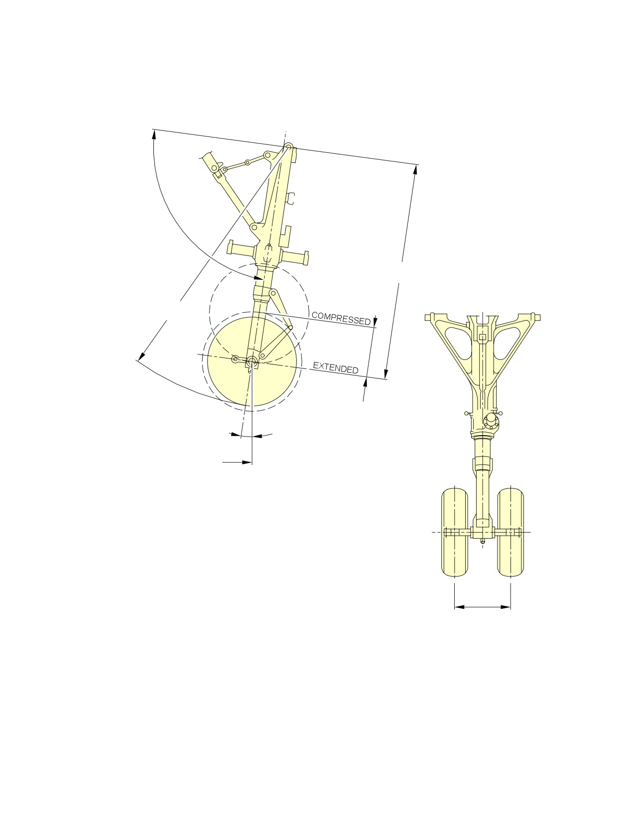
92°
1 957.03 mm
(77.05 in)
2 338 mm
(92.05 in)
430 mm
(16.93 in)
9°
7 561 mm
X =
(297.68 in)
500 mm
(19.69 in)
N_AC_020900_1_0050101_01_00
Landing Gear
Nose Landing Gear Dimensions
FIGURE-2-9-0-991-005-A01
Page 8
May 01/16
2-9-0
@A318
AIRCRAFT CHARACTERISTICS - AIRPORT AND MAINTENANCE PLANNING
**ON A/C A318-100
Landing Gear Maintenance Pits
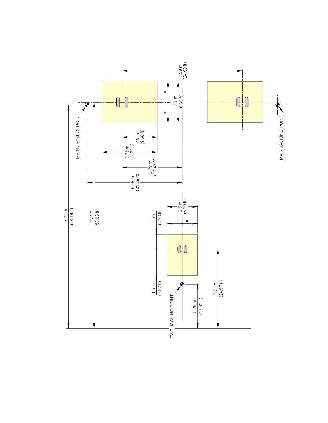
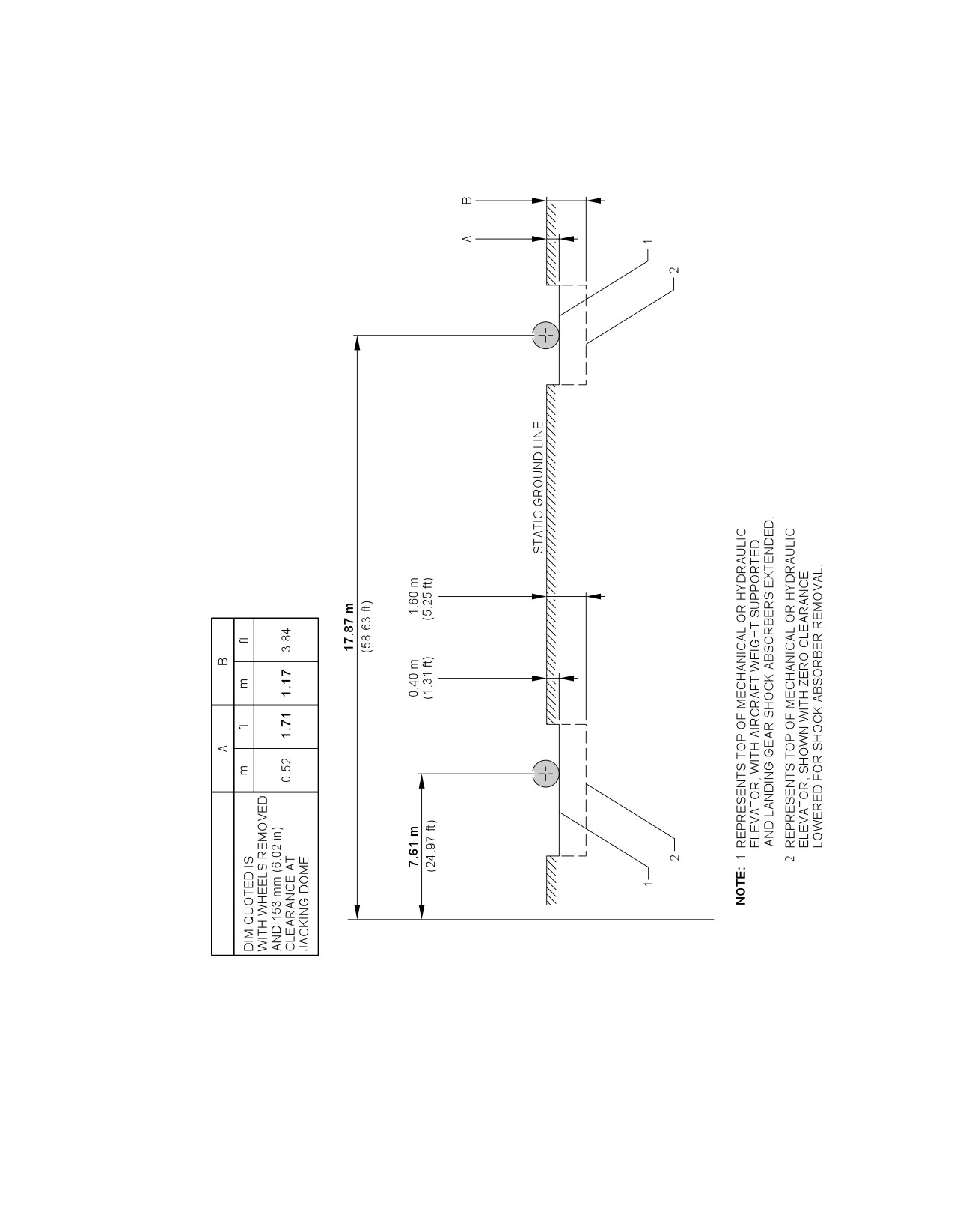
1.
Description
The minimum maintenance pit envelopes for the landing-gear shock absorber removal are shown in
FIGURE 2-9-0-991-020-A and FIGURE 2-9-0-991-021-A.
All dimensions shown are minimum dimensions with zero clearances.
The dimensions for the pits have been determined as follows:
-
The length and width of the pits allow the gear to rotate as the weight is taken off the landing
gear.
-
The depth of the pits allows the shock absorber to be removed when all the weight is taken off
the landing gear.
Dimensions for elevators and associated mechanisms must be added to those in FIGURE
2-9-0-991-020-A and FIGURE 2-9-0-991-021-A.
Page 9
May 01/16
2-9-0
@A318
AIRCRAFT CHARACTERISTICS - AIRPORT AND MAINTENANCE PLANNING
**ON A/C A318-100
FROM X0
N_AC_020900_1_0200101_01_00
Landing Gear Maintenance Pits
Maintenance Pit Envelopes
FIGURE-2-9-0-991-020-A01
Page 10
May 01/16
2-9-0
@A318
AIRCRAFT CHARACTERISTICS - AIRPORT AND MAINTENANCE PLANNING
**ON A/C A318-100
FROM X0
N_AC_020900_1_0210101_01_00
Landing Gear Maintenance Pits
Maintenance Pit Envelopes
FIGURE-2-9-0-991-021-A01
Page 11
May 01/16
2-9-0
@A318
AIRCRAFT CHARACTERISTICS - AIRPORT AND MAINTENANCE PLANNING
2-10-0
Exterior Lighting
**ON A/C A318-100
Exterior Lighting
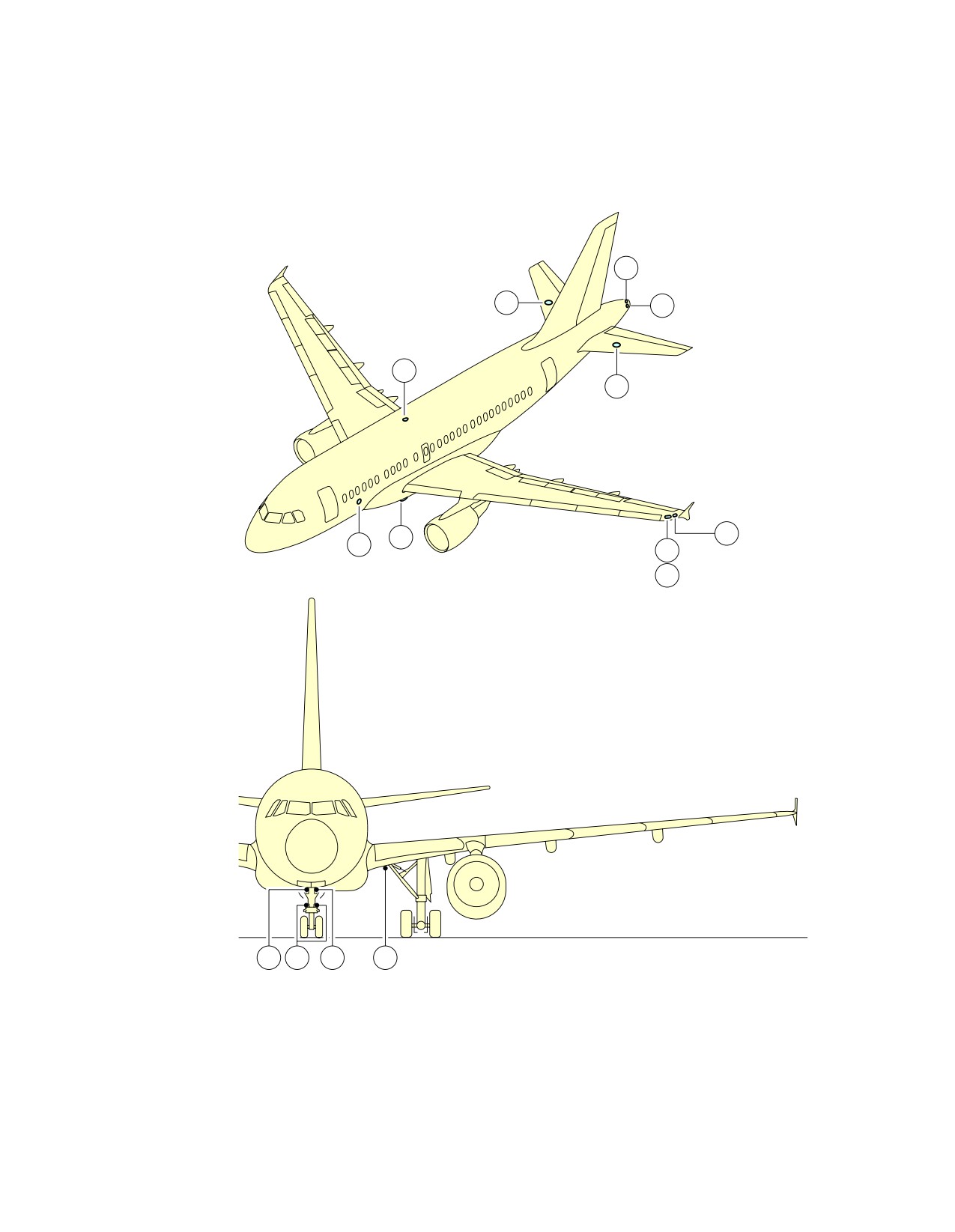
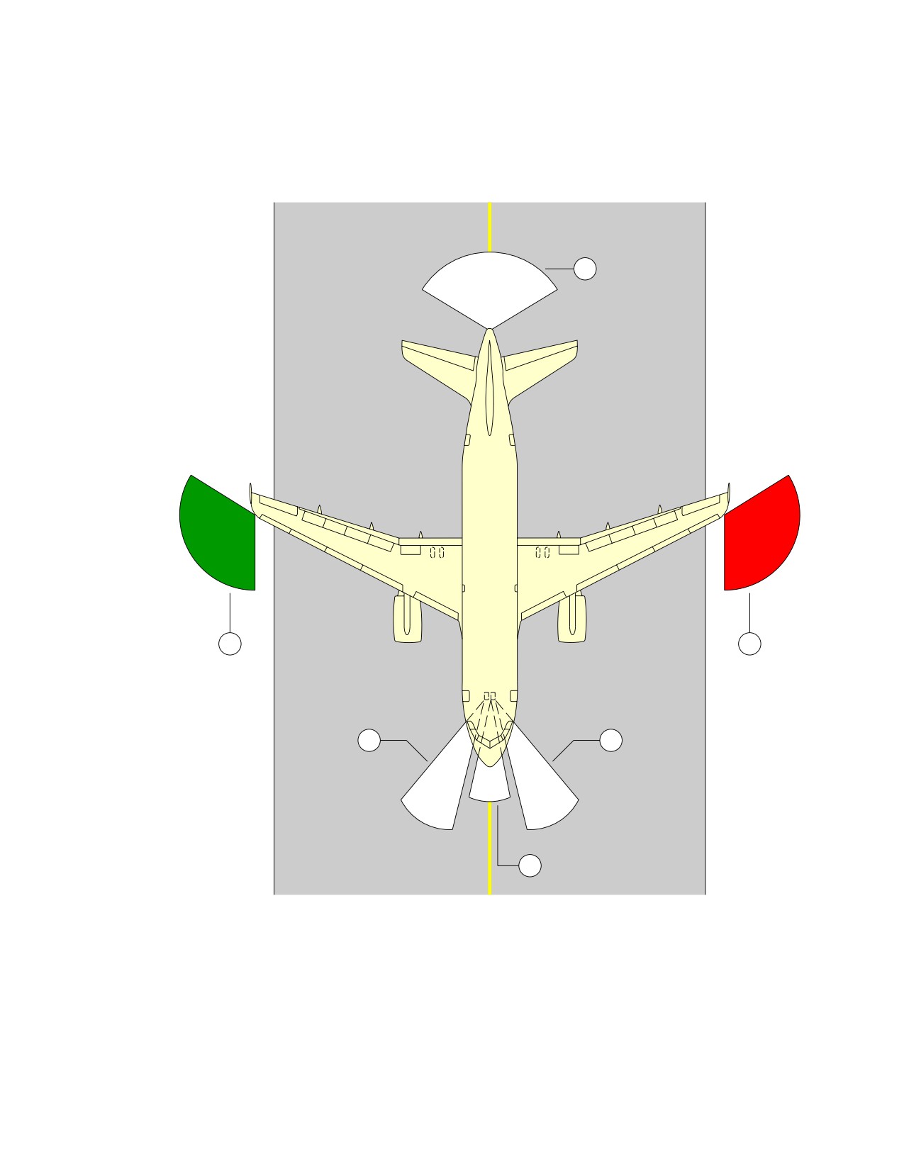
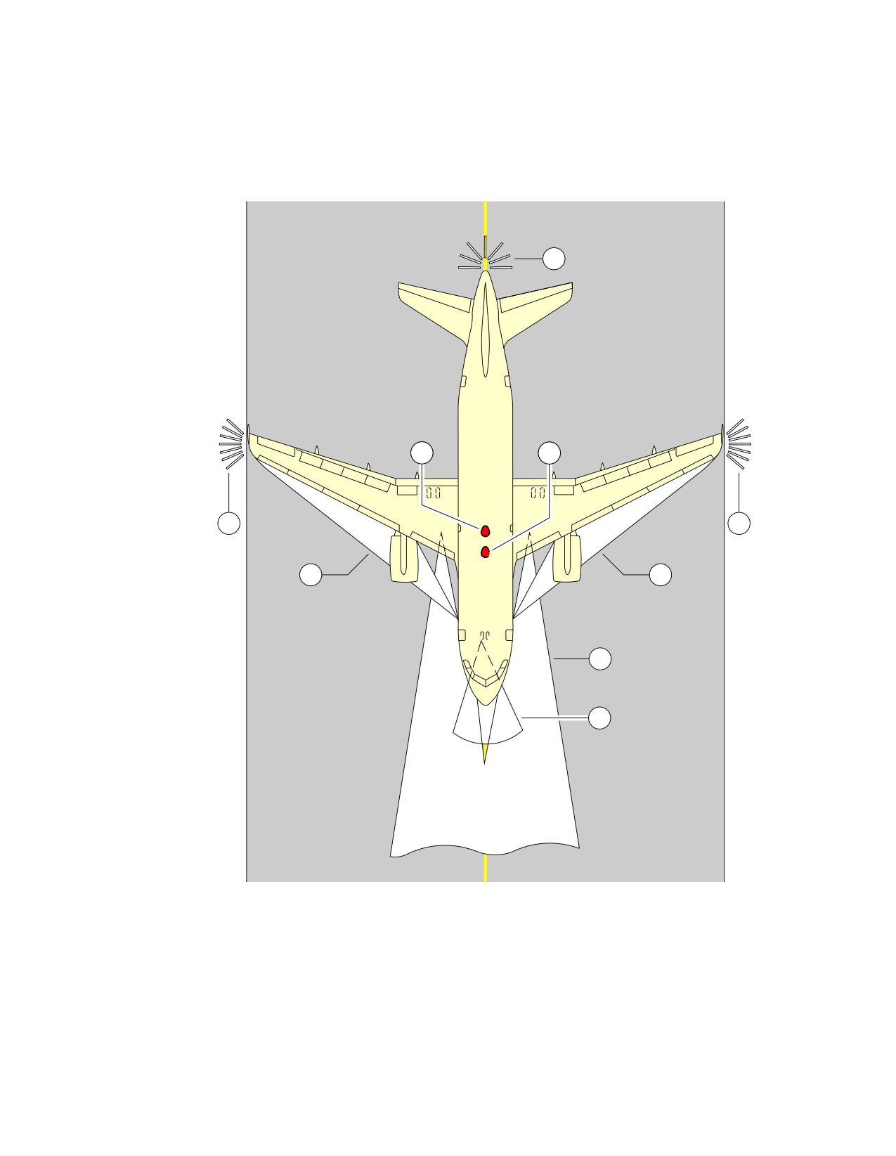
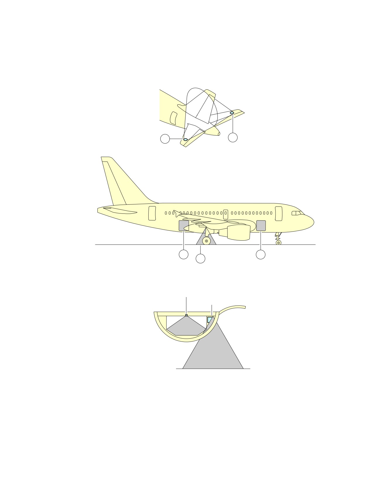
1.
General
This section provides the location of the aircraft exterior lighting.
EXTERIOR LIGHTING
ITEM
DESCRIPTION
1
RIGHT NAVIGATION LIGHT (GREEN)
2
TAIL NAVIGATION LIGHT (WHITE)
3
LEFT NAVIGATION LIGHT (RED)
4
RETRACTABLE LANDING LIGHT
5
RUNWAY TURN OFF LIGHT
6
TAXI LIGHT
7
TAKE-OFF LIGHT
8
LOGO LIGHT
9
UPPER ANTI-COLLISION LIGHT/BEACON (RED)
10
LOWER ANTI-COLLISION LIGHT/BEACON (RED)
11
WING STROBE LIGHT (HIGH INTENSITY, WHITE)
12
TAIL STROBE LIGHT (HIGH INTENSITY, WHITE)
13
WING/ENGINE SCAN LIGHT
14
WHEEL WELL LIGHT (DOME)
15
CARGO COMPARTMENT FLOOD LIGHT
Page 1
May 01/16
2-10-0
@A318
AIRCRAFT CHARACTERISTICS - AIRPORT AND MAINTENANCE PLANNING
**ON A/C A318-100
2
8
12
9
8
10
11
13
RH
1
LH
3
6
5
7
4
N_AC_021000_1_0010101_01_01
Exterior Lighting
FIGURE-2-10-0-991-001-A01
Page 2
May 01/16
2-10-0
@A318
AIRCRAFT CHARACTERISTICS - AIRPORT AND MAINTENANCE PLANNING
**ON A/C A318-100
2
1
3
5
5
7
N_AC_021000_1_0020101_01_01
Exterior Lighting
FIGURE-2-10-0-991-002-A01
Page 3
May 01/16
2-10-0
@A318
AIRCRAFT CHARACTERISTICS - AIRPORT AND MAINTENANCE PLANNING
**ON A/C A318-100
12
9
10
11
11
13
13
4
6
N_AC_021000_1_0030101_01_01
Exterior Lighting
FIGURE-2-10-0-991-003-A01
Page 4
May 01/16
2-10-0
@A318
AIRCRAFT CHARACTERISTICS - AIRPORT AND MAINTENANCE PLANNING
**ON A/C A318-100
8
8
15
15
14
EXAMPLE FOR LIGHT N° 15
CEILING LIGHT
SPOT LIGHT
GROUND
N_AC_021000_1_0170101_01_01
Exterior Lighting
FIGURE-2-10-0-991-017-A01
Page 5
May 01/16
2-10-0
@A318
AIRCRAFT CHARACTERISTICS - AIRPORT AND MAINTENANCE PLANNING
2-11-0
Antennas and Probes Location
**ON A/C A318-100
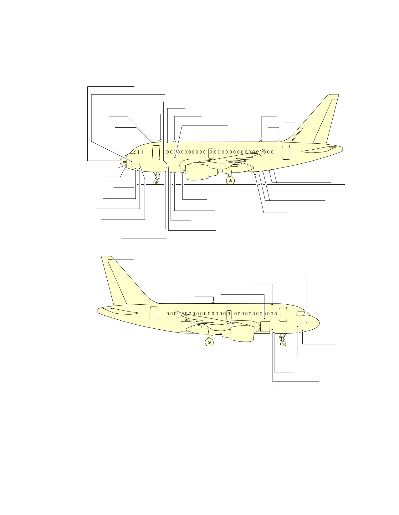
Antennas and Probes Location
1.
This section gives the location of antennas and probes.
Page 1
May 01/16
2-11-0
@A318
AIRCRAFT CHARACTERISTICS - AIRPORT AND MAINTENANCE PLANNING
**ON A/C A318-100
WEATHER RADAR
EMERGENCY STATIC PROBE
AOA SENSOR(3) STBY
ATC(4)
VHF(1)
GPS(2)
TCAS TOP
VHF(3)
HF
AOA SENSOR(1)
GPS(1)
ELT
LOC
GLIDE
RADIO ALTIMETER(2)
DME(1)
TAT PROBE
MARKER
RADIO ALTIMETER(1)
PITOT PROBE(3)
TCAS BOTTOM
VHF(2)
PITOT PROBE(1)
DME(2)
ATC(1)
STATIC PROBE(1)
STATIC PROBE(2)
VOR
EMERGENCY STATIC PROBE
ATC(3)
AOA SENSOR(2)
ADF(1)
TAT PROBE
PITOT PROBE(2)
ATC(2)
STATIC PROBE(1)
STATIC PROBE(2)
NOTE: DEPENDING ON AIRCRAFT CONFIGURATION
N_AC_021100_1_0010101_01_00
Antennas and Probes
Location
FIGURE-2-11-0-991-001-A01
Page 2
May 01/16
2-11-0
@A318
AIRCRAFT CHARACTERISTICS - AIRPORT AND MAINTENANCE PLANNING
2-12-0
Power Plant
**ON A/C A318-100
Auxiliary Power Unit
1.
General
The APU is installed at the rear part of the fuselage in the tail cone. An air intake system with a
flap-type door is installed in front of the APU compartment. The exhaust gases pass overboard at the
end of the fuselage cone.
2.
Controls and Indication
The primary APU controls and indications are installed on the overhead panel, on the center pedestal
and on the center instrument panel. Additionally, an external APU panel is installed on the nose
landing gear to initiate an APU emergency shutdown.
Page 1
May 01/16
2-12-0
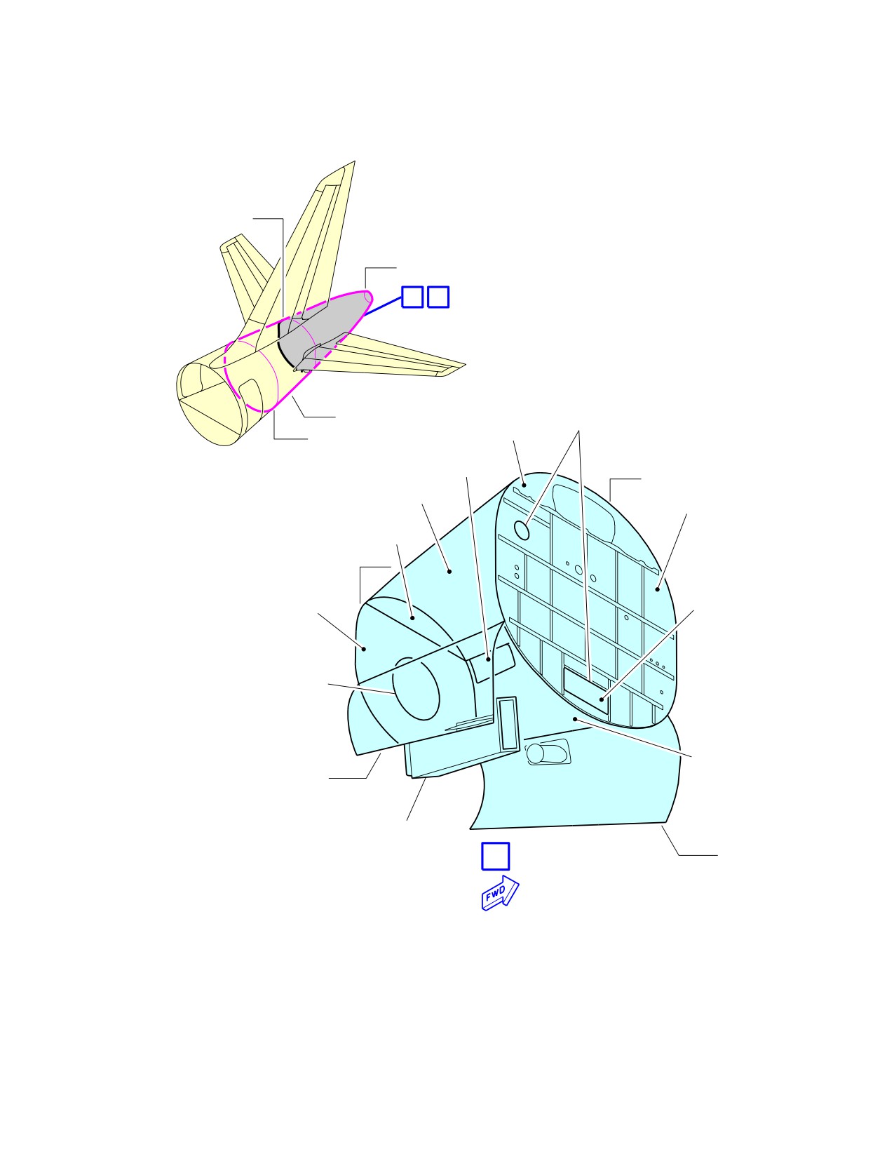
@A318
AIRCRAFT CHARACTERISTICS - AIRPORT AND MAINTENANCE PLANNING
**ON A/C A318-100
FR76
FR87
A
B
Z310
CUT OUT SEALED
UPPER
WITH LABYRINTH GASKET
FR70
FIREWALL
VENT
LOUVER
FR80
RH FIREWALL
FRONT FIREWALL
UPPER
FIREWALL
FR84
AIR INTAKE
CUT OUT
REAR FIREWALL
CUT OUT SEALED WITH
LABYRINTH GASKET
LH FIREWALL
316AR
AIR INTAKE FIXED
ON ACCESS DOOR
315AL
A
N_AC_021200_1_0010101_01_01
Auxiliary Power Unit
Access Doors
FIGURE-2-12-0-991-001-A01
Page 2
May 01/16
2-12-0
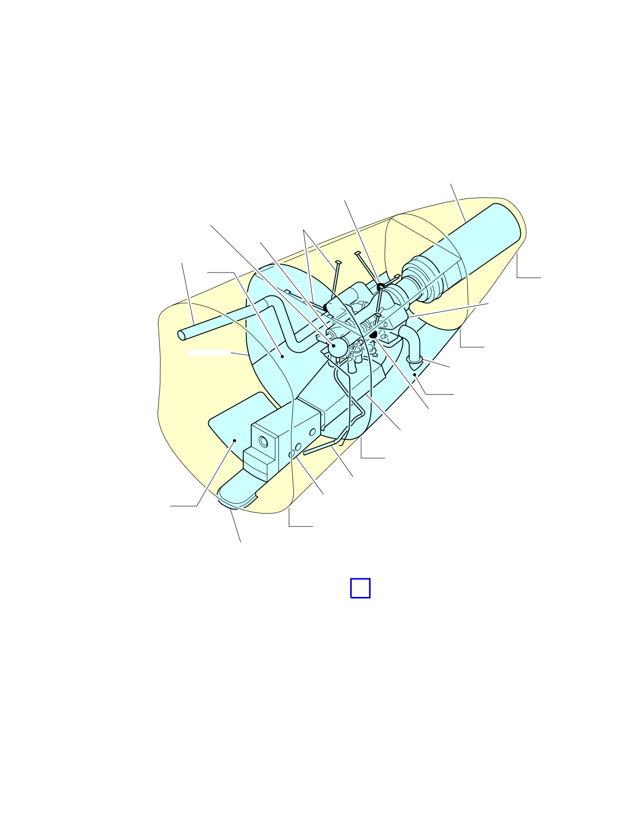
@A318
AIRCRAFT CHARACTERISTICS - AIRPORT AND MAINTENANCE PLANNING
**ON A/C A318-100
EXHAUST MUFFLER
AFT APU MOUNT
FIRE EXTINGUISHING
APU SUSPENSION
BOTTLE
(7 RODS)
GENERATOR
BLEED AIR LINE
316AR
FR87
OIL COOLER
FR84
FIREWALL
OIL COOLER OUTLET
315AL
LH FORWARD APU MOUNT
AIR INTAKE DUCT
FR80
APU−FUEL−LINE
314AR
AIR INTAKE HOUSING
FR76
FIXED DIVERTER
B
N_AC_021200_1_0020101_01_01
Auxiliary Power Unit
General Layout
FIGURE-2-12-0-991-002-A01
Page 3
May 01/16
2-12-0
@A318
AIRCRAFT CHARACTERISTICS - AIRPORT AND MAINTENANCE PLANNING
**ON A/C A318-100
Engine and Nacelle
1.
Engine and Nacelle - CFM Engine
A.
Engine
The engine is a dual-rotor, variable stator, high bypass ratio turbo fan power plant for subsonic
services. The principal modules of the engine are:
-
low pressure compressor (fan stator and fan rotor)
-
high pressure compressor
-
turbine frame
-
combustion chamber
-
high pressure turbine
-
low pressure turbine
-
accessory drives (gear box).
The 9 stage high pressure compressor is driven by 1 stage high pressure turbine, and the
integrated front fan and booster is driven by 4 stage low pressure turbine. An annular combustor
converts fuel and compressor discharge air into energy to provide engine thrust part through
primary exhaust and to drive the turbines. The accessory drive system extracts energy from the
high pressure rotor to drive the engine accessories and the engine mounted aircraft accessories.
Reverse thrust for braking the aircraft after landing is supplied by an integrated system which
acts on the fan discharge airflow.
B.
Nacelle
The cowls enclose the periphery of the engine so as to form the engine nacelle. Each engine is
housed in a nacelle suspended from a pylon attached to the wing lower surface. The nacelle
consists of the demountable powerplant, the fan cowls and the thrust reverser cowls.
The nacelle installation is designed to provide cooling and ventilation air for engine accessories
mounted along the fan and core casing. The nacelle provides:
-
protection for the engine and the accessories
-
airflow around the engine during its operation
-
lighting protection
-
HIRF and EMI attenuation.
2.
Engine and Nacelle - PW Engine
A. Engine
The engine is a two spool, axial flow, high bypass ratio turbofan powerplant for subsonic sevice.
The main modules of the engine are:
-
compressor section
-
combustion section
-
turbine section
-
accessory drives (gear box) section.
The four stage Low Pressure Compressor (LPC) is driven by a three stage Low Pressure Turbine
(LPT) and the six stage High Pressure Compressor (HPC) by a single stage High Pressure
Turbine (HPT).
Page 4
May 01/16
2-12-0
@A318
AIRCRAFT CHARACTERISTICS - AIRPORT AND MAINTENANCE PLANNING
The PW6000 incorporates a Full Authority Digital Engine Control (FADEC) which governs all
engine functions, including power management.
B. Nacelle
The cowls enclose the periphery of the engine so as to form the engine nacelle. Each engine is
housed in a nacelle suspended from a pylon attached below the wing.
The nacelle installation is designed to provide cooling and ventilation air for engine accessories
mounted along the fan and core casing. The nacelle provides:
-
protection for the engine and the accessories
-
airflow around the engine during its operation
-
lighting protection
-
HIRF and EMI attenuation.
Page 5
May 01/16
2-12-0
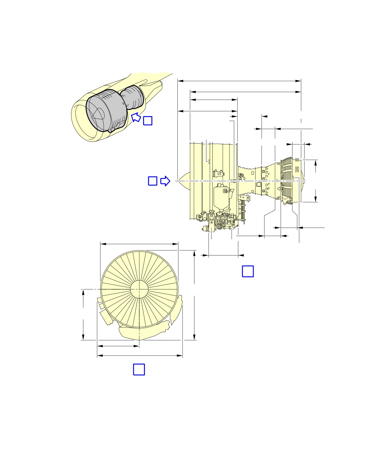
@A318
AIRCRAFT CHARACTERISTICS - AIRPORT AND MAINTENANCE PLANNING
**ON A/C A318-100
2 943 mm
(115.87 in)
2 600 mm
(102.36 in)
1 125 mm
(44.28 in)
FAN AND
BOOSTER
COMPRESSOR
A
FWD HANDLING
POINT
COMBUSTOR
FWD HOISTING
POINT
TURBINE FRAME
DIA
986 mm
B
(38.82 in)
LP
TURBINE
HP
TURBINE
1 820 mm
AGB TGB
(71.65 in)
AFT HOISTING AND
ACCESSORY
HANDLING POINT
DRIVE
A
2 145 mm
(84.45 in)
1 130 mm
(44.49 in)
989 mm
(38.94 in)
1 978 mm
(77.87 in)
B
N_AC_021200_1_0110101_01_00
Power Plant Handling
Major Dimensions - CFM56 Series Engine
FIGURE-2-12-0-991-011-A01
Page 6
May 01/16
2-12-0
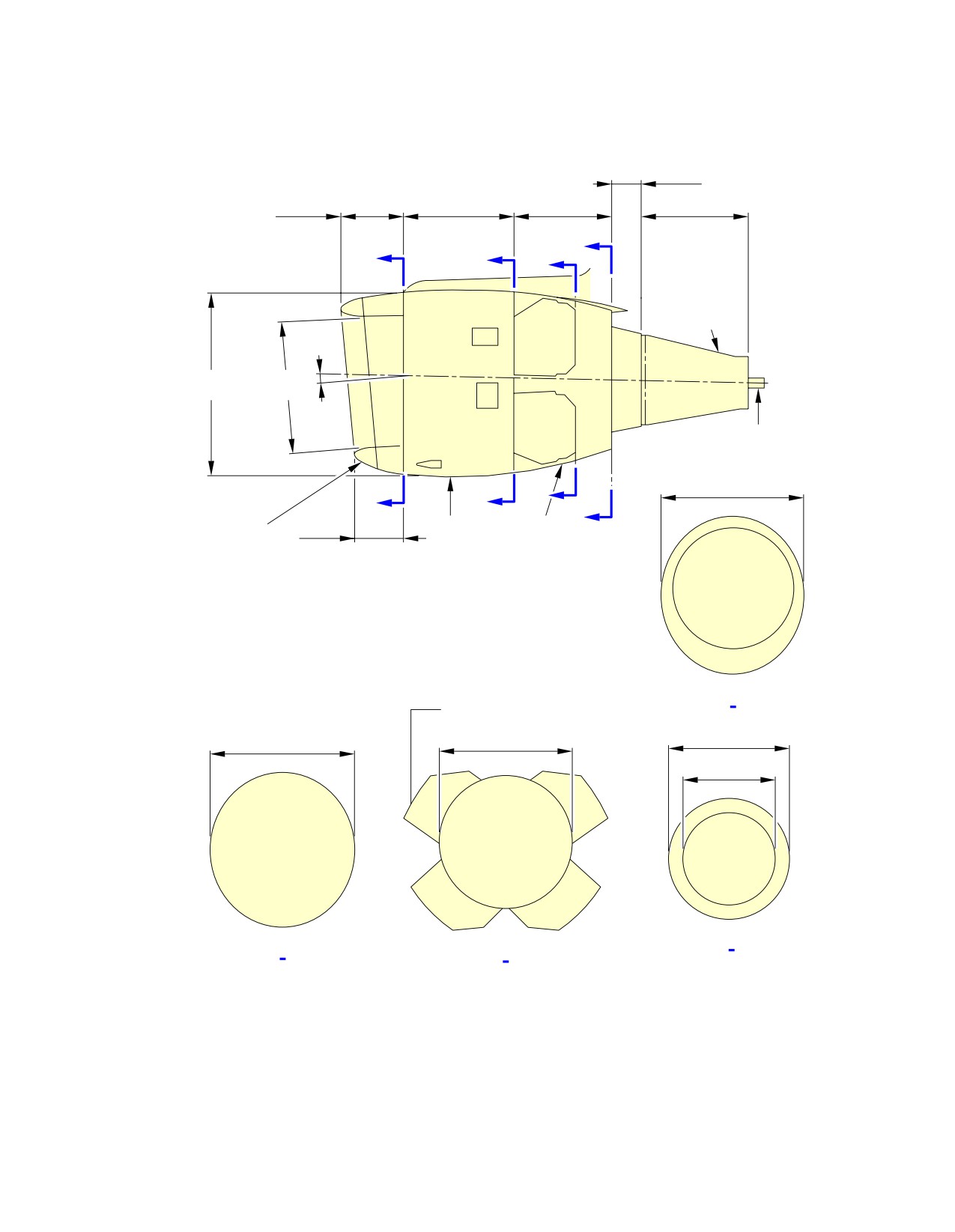
@A318
AIRCRAFT CHARACTERISTICS - AIRPORT AND MAINTENANCE PLANNING
**ON A/C A318-100
DISTANCE FROM
0.33 m
THE NOSE
(1.1 ft)
8.8 m
0.93 m
1.3 m
1.2 m
1.2 m
(28.9 in)
(3.1 ft)
(4.3 ft)
(3.9 ft)
(3.9 ft)
D
A
B
C
PRIMARY
NOZZLE
6°
2.3 m
1.6 m
(7.5 ft)
(5.2 ft)
CENTERBODY
2.1 m
C
A
B
(6.9 ft)
D
ENGINE AIR
FAN COWL
FAN
0.57 m
REVERSER
INLET COWL
(1.9 ft)
BLOCKER DOOR
A A
EXTENDED
1.9 m
1.8 m
2.07 m
(6.2 ft)
(5.9 ft)
(6.8 ft)
1.2 m
(3.9 ft)
D D
B B
C C
N_AC_021200_1_0120101_01_00
Power Plant Handling
Major Dimensions - CFM56 Series Engine
FIGURE-2-12-0-991-012-A01
Page 7
May 01/16
2-12-0
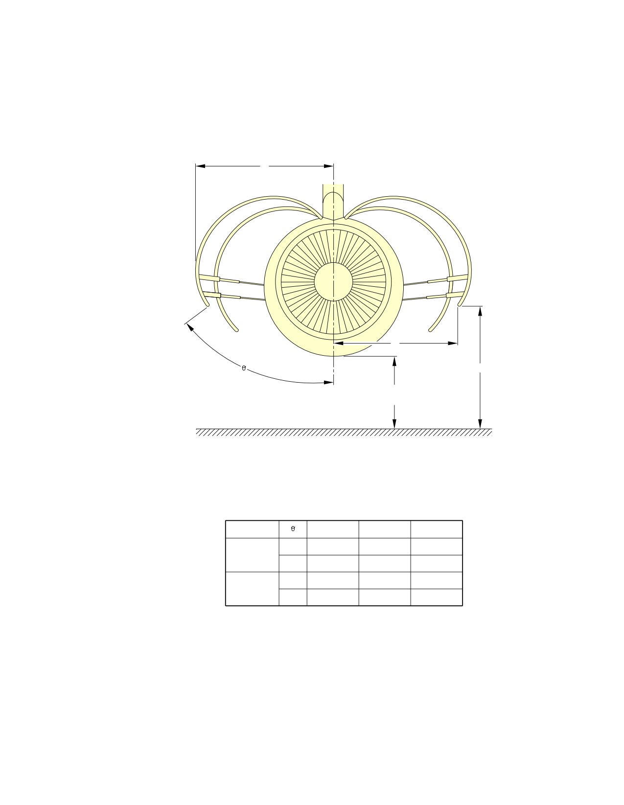
@A318
AIRCRAFT CHARACTERISTICS - AIRPORT AND MAINTENANCE PLANNING
**ON A/C A318-100
A
B
C
0.55 m
(1.8 ft)
NOTE: APPROXIMATE DIMENSIONS
m (ft)
A
B
C
VIEW
42°27
1.8
(5.9)
1.5
(4.9)
1.3
(4.3)
COWLING
AFT
55°15
2.0
(6.6)
1.8
(5.9)
1.7
(5.6)
VIEW
40°40
1.8
(5.9 )
1.4
(4.6)
1.3
(4.3)
COWLING
FWD
52°56
2.0
(6.6)
1.7
(5.6)
1.6
(5.2)
N_AC_021200_1_0130101_01_00
Power Plant Handling
Fan Cowls - CFM56 Series Engine
FIGURE-2-12-0-991-013-A01
Page 8
May 01/16
2-12-0
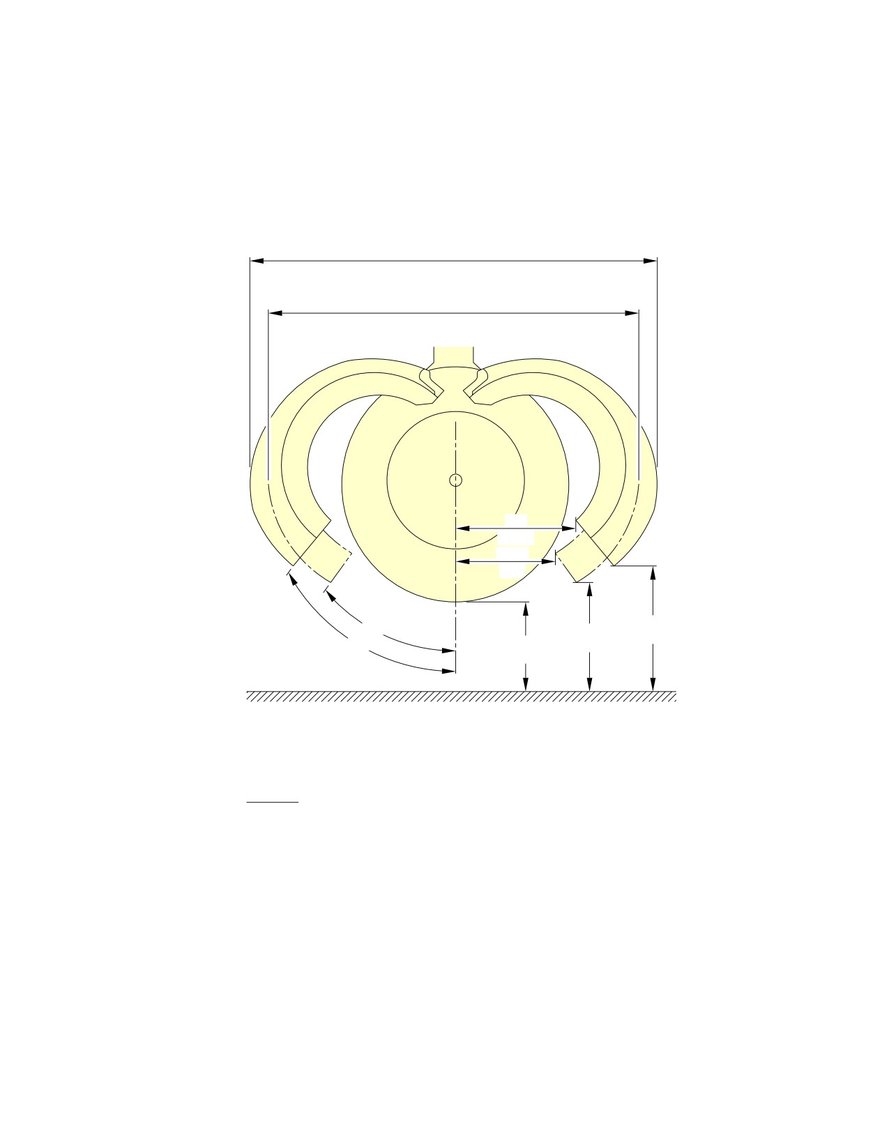
@A318
AIRCRAFT CHARACTERISTICS - AIRPORT AND MAINTENANCE PLANNING
**ON A/C A318-100
3.7 m
(12.1 ft)
3.3 m
(10.8 ft)
1 m
(3.3 ft)
0.9 m
(3 ft)
1 m
35°
0.7 m
(3.3 ft)
45°
0.5 m
(2.3 ft)
(1.6 ft)
GROUND
NOTE: APPROXIMATE DIMENSIONS
CAUTION
DO NOT ACTUATE SLATS:
− WITH THRUST REVERSER COWLS 45° OPEN POSITION
− WITH BLOCKER DOORS OPEN AND THRUST REVERSER
COWLS AT 35° AND 45° OPEN POSITION
N_AC_021200_1_0140101_01_00
Power Plant Handling
Thrust Reverser Cowls - CFM56 Series Engine
FIGURE-2-12-0-991-014-A01
Page 9
May 01/16
2-12-0
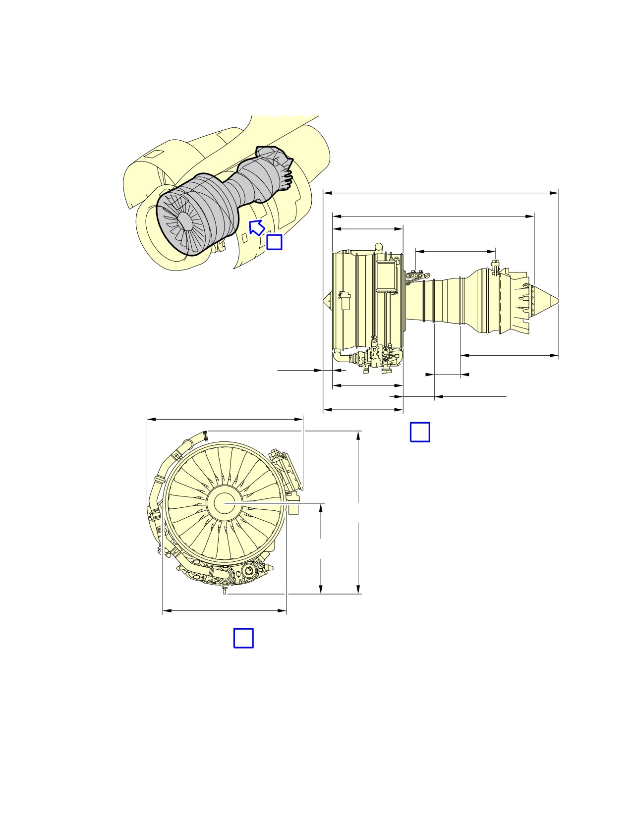
@A318
AIRCRAFT CHARACTERISTICS - AIRPORT AND MAINTENANCE PLANNING
**ON A/C A318-100
3 746 mm
(147.50 in)
3 355 mm
(132.10 in)
1 146 mm
(45.12 in)
A
1 245 mm
(49.02 in)
TURBINE SECTION
142 mm
COMBUSTOR
(5.59 in)
ACCESSORY
DRIVE
COMPRESSOR
FAN AND
2 002 mm
BOOSTER
(78.82 in)
A
2 098 mm
(82.60 in)
1 151 mm
(45.31 in)
1 590 mm
(62.60 in)
B
N_AC_021200_1_0150101_01_00
Power Plant Handling
Major Dimensions - PW 6000 Series Engine
FIGURE-2-12-0-991-015-A01
Page 10
May 01/16
2-12-0
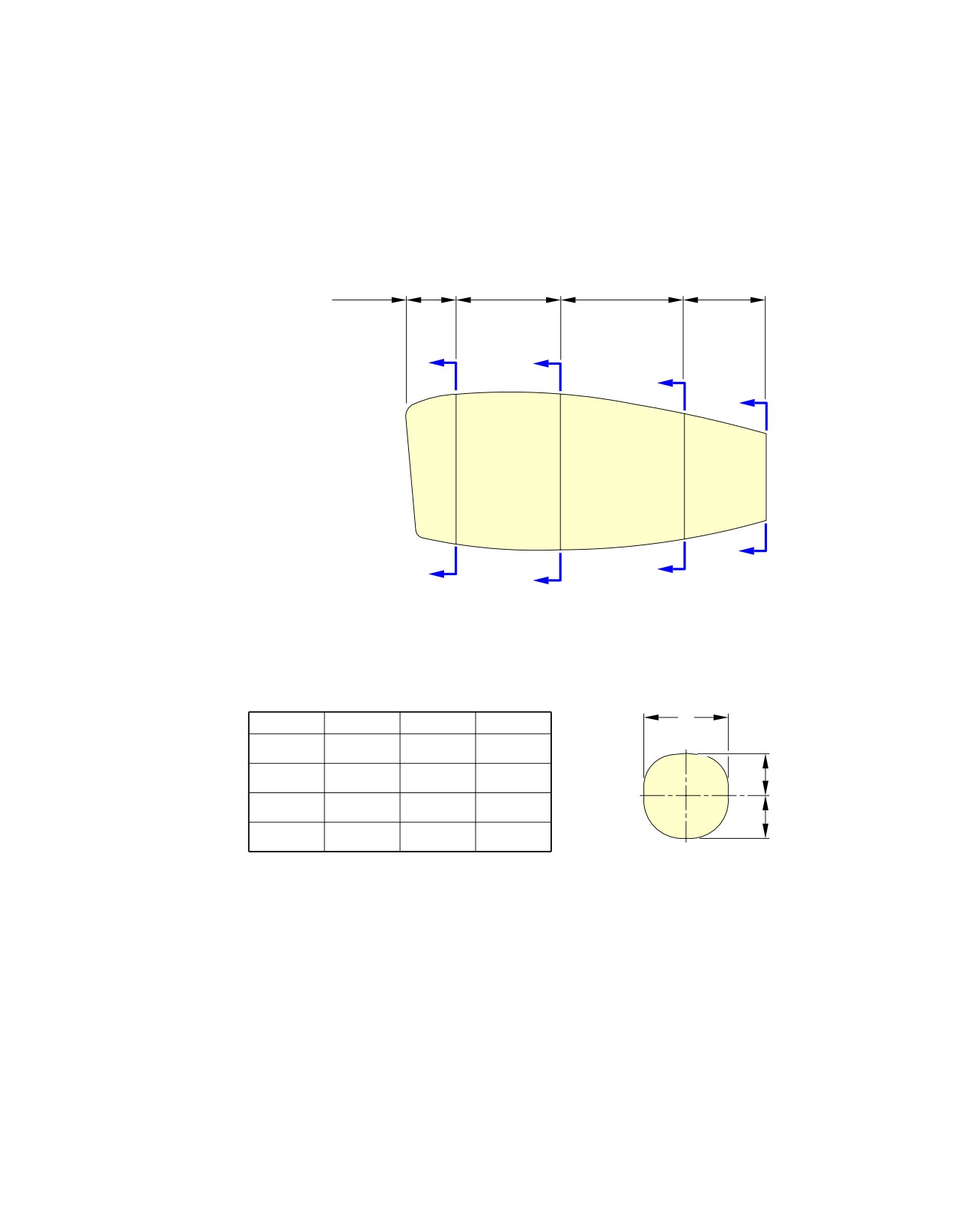
@A318
AIRCRAFT CHARACTERISTICS - AIRPORT AND MAINTENANCE PLANNING
**ON A/C A318-100
AIR INTAKE
THRUST COMMON NOZZLE
COWL FAN COWL
REVERSER
ASSY
DISTANCE
8.85 m
1.03 m
1.24 m
1.66 m
1.43 m
FROM THE
NOSE
(29 ft)
(3.37 ft)
(4.1 ft)
(5.44 ft)
(4.7 ft)
A
B
C
D
D
C
A
B
W
W
U
V
2 m
0.9 m
1.05 m
A−A
(6.6 ft)
(3 ft)
(3.4 ft)
2.08 m
0.96 m
1.07 m
U
B−B
(6.8 ft)
(3.1 ft)
(3.5 ft)
1.63 m
0.76 m
0.81 m
C−C
(5.3 ft)
(2.5 ft)
(2.7 ft)
V
1.12 m
0.56 m
0.56 m
D−D
(3.7 ft)
(1.8 ft)
(1.8 ft)
NOTE:
ALL SIZES GIVEN ON THIS ILLUSTRATION ARE APPROXIMATE
N_AC_021200_1_0160101_01_00
Power Plant Handling
Nacelle Dimensions - PW 6000 Series Engine
FIGURE-2-12-0-991-016-A01
Page 11
May 01/16
2-12-0
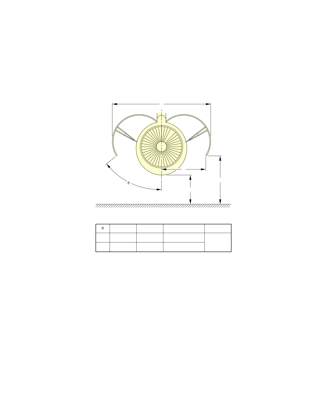
@A318
AIRCRAFT CHARACTERISTICS - AIRPORT AND MAINTENANCE PLANNING
**ON A/C A318-100
A
B
C
°
D
GROUND
A
B
C
D
3.05 m
0.90 m
D + 0.2 m
27°
(10 ft)
(2.95 ft)
(D + 0.7 ft)
0.7 m
3.85 m
1.65 m
D + 0.84 m
(2.3 ft)
53°
(12.63 ft)
(5.41 ft)
(D + 2.8 ft)
NOTE: APPROXIMATE DIMENSIONS
ONLY MAIN DIMENSIONS SHOWN
N_AC_021200_1_0170101_01_00
Power Plant Handling
Fan Cowls - PW 6000 Series Engine
FIGURE-2-12-0-991-017-A01
Page 12
May 01/16
2-12-0
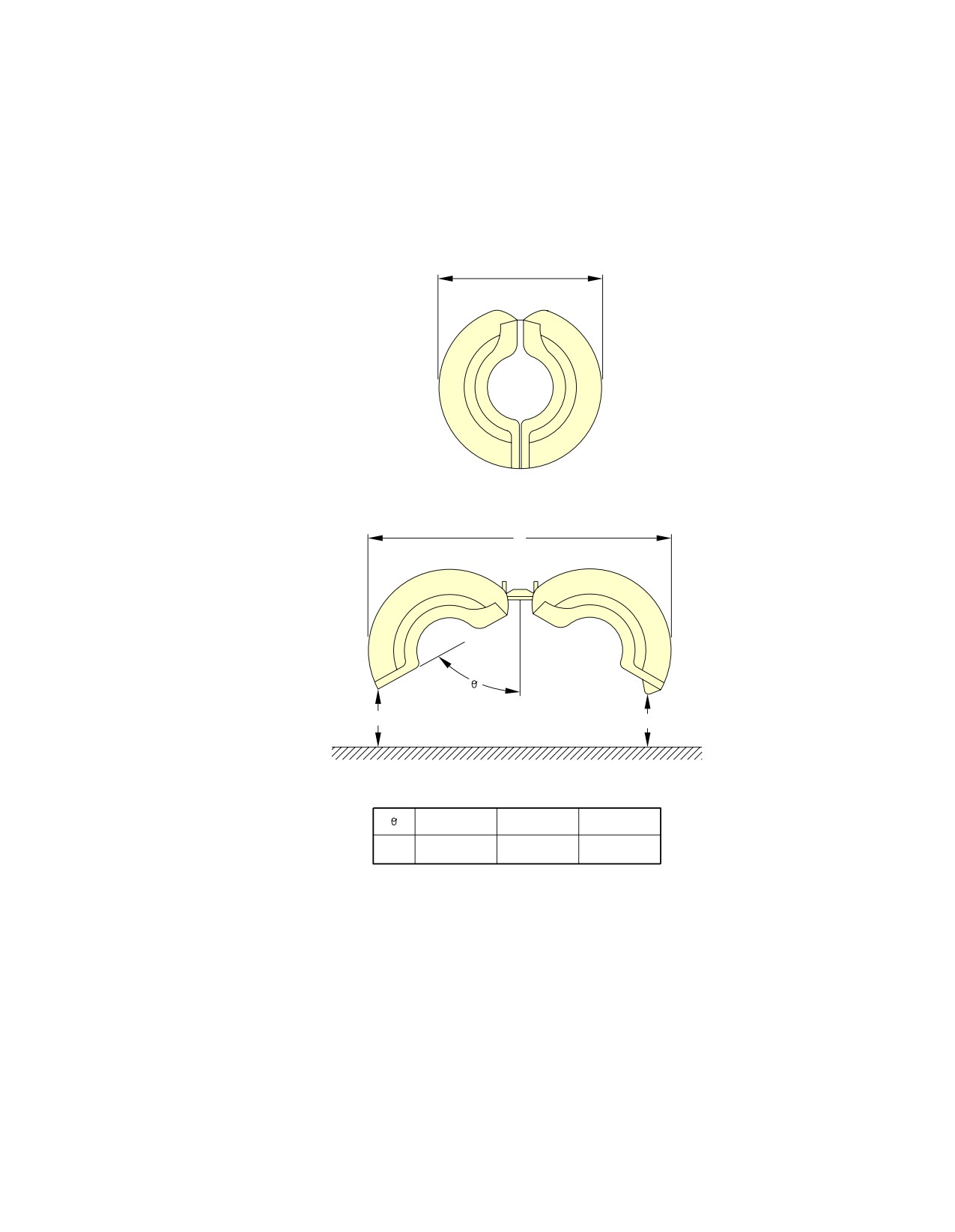
@A318
AIRCRAFT CHARACTERISTICS - AIRPORT AND MAINTENANCE PLANNING
**ON A/C A318-100
2.08 m
(6.82 ft)
CLOSED
A
OPEN
°
B
C
GROUND
A
B
C
3.5 m
1.1 m
1.08 m
45°
(11.48 ft)
(3.6 ft)
(3.5 ft)
N_AC_021200_1_0180101_01_00
Power Plant Handling
Thrust Reverser Halves - PW 6000 Series Engine
FIGURE-2-12-0-991-018-A01
Page 13
May 01/16
2-12-0
@A318
AIRCRAFT CHARACTERISTICS - AIRPORT AND MAINTENANCE PLANNING
2-13-0
Leveling, Symmetry and Alignment
**ON A/C A318-100
Leveling, Symmetry and Alignment
1.
Quick Leveling
There are three alternative procedures to level the aircraft:
-
Quick leveling procedure with Air Data/Inertial Reference Unit (ADIRU).
-
Quick leveling procedure with a spirit level in the passenger compartment.
-
Quick leveling procedure with a spirit level in the FWD cargo compartment.
2.
Precise Leveling
For precise leveling, it is necessary to install sighting rods in the receptacles located under the
fuselage (points 11 and 12 for longitudinal leveling) and under the wings (points 2LH and 2RH for
lateral leveling) and use a sighting tube. With the aircraft on jacks, adjust the jacks until the
reference marks on the sighting rods are aligned in the sighting plane (aircraft level).
3.
Symmetry and Alignment Check
Possible deformation of the aircraft is measured by photogrammetry.
Page 1
May 01/16
2-13-0
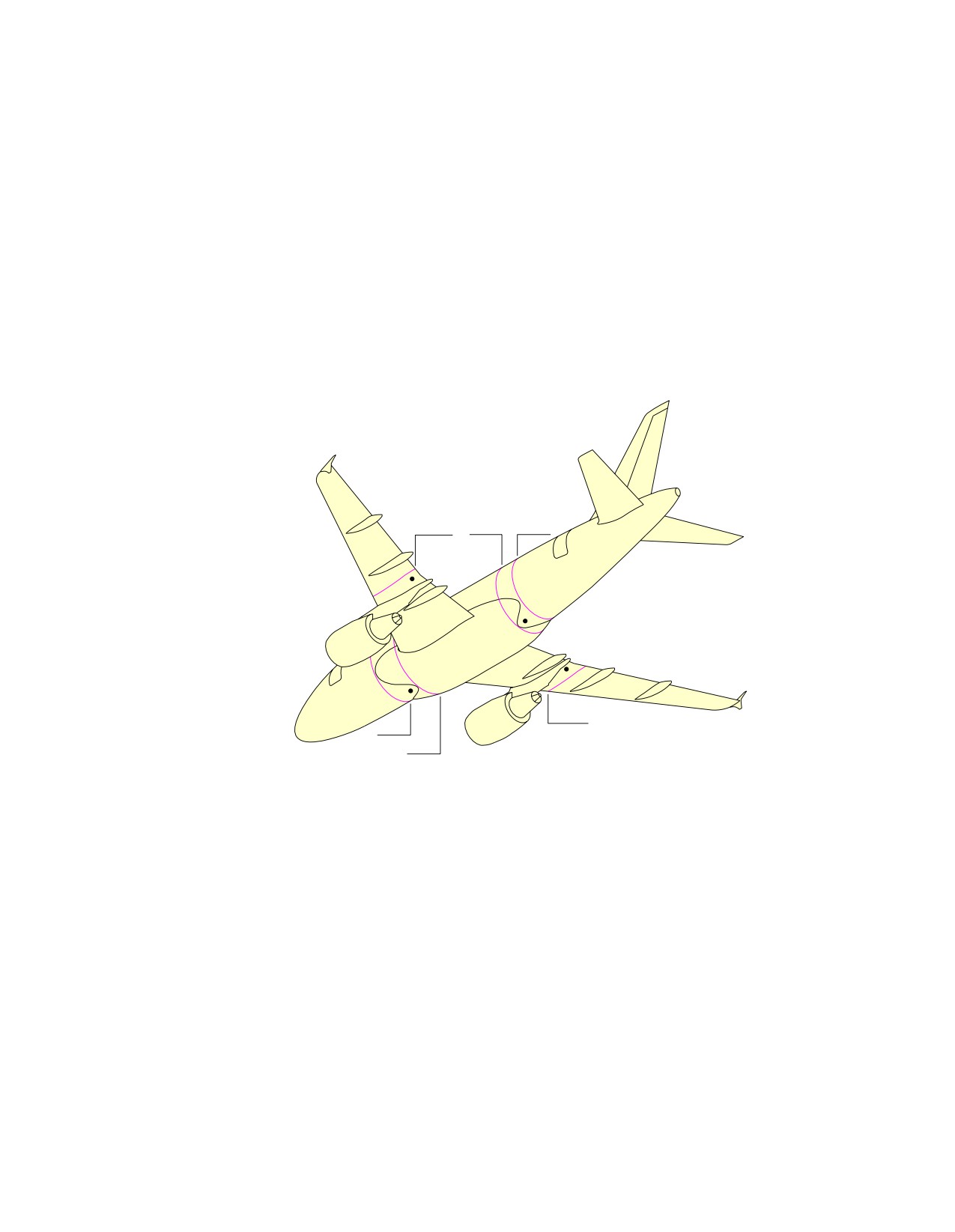
@A318
AIRCRAFT CHARACTERISTICS - AIRPORT AND MAINTENANCE PLANNING
**ON A/C A318-100
RIB10
FR54
FR57
2LH
12
2RH
11
RIB10
FR28
FR34
N_AC_021300_1_0010101_01_00
Location of the Leveling Points
FIGURE-2-13-0-991-001-A01
Page 2
May 01/16
2-13-0
@A318
AIRCRAFT CHARACTERISTICS - AIRPORT AND MAINTENANCE PLANNING
2-14-0
Jacking
**ON A/C A318-100
Jacking for Maintenance
1.
Aircraft Jacking Points for Maintenance
A.
General
(1) The A318 can be jacked:
-
At not more than 53 000 kg (116 845 lb),
-
Within the limits of the permissible wind speed when the aircraft is not in a closed
environment.
B.
Primary Jacking Points
(1) The aircraft is provided with three primary jacking points:
-
One located under the forward fuselage (FR8),
-
Two located under the wings (one under each wing, located at the intersection of RIB9
and the datum of the rear spar).
(2) Three jack adapters are used as intermediary parts between the aircraft and the jacks:
-
One male spherical jack adapter of 19 mm (0.75 in) radius, forming part of the aircraft
structure (FR8),
-
Two wing jack pads (one attached to each wing at RIB9 with 2 bolts) for the location
of the jack adaptor.
Wing jack pads are ground equipment.
C.
Auxiliary Jacking Points (Safety Stay)
(1) When the aircraft is on jacks, it is recommended that a safety stay be placed under the
fuselage, between FR73 and FR74, to prevent tail tipping caused by accidental
displacement of the center of gravity.
(2) The safety stay must not be used to lift the aircraft.
(3) A male spherical ball pad with a 19 mm (0.75 in) radius, forming part of the aircraft
structure, is provided for using the safety stay.
2.
Jacks and Safety Stay
A. Jack Design
(1) The maximum permitted loads given in the table in FIGURE 2-14-0-991-001-A are the
maximum loads applicable on jack fittings.
(2) In the fully retracted position (jack stroke at minimum), the height of the jack is such that
the jack may be placed beneath the aircraft in the most adverse conditions, namely, tires
deflated and shock absorbers depressurized. In addition, there must be a clearance of
approximately 50 mm (1.97 in) between the aircraft jacking point and the jack upper end.
Page 1
May 01/16
2-14-0
@A318
AIRCRAFT CHARACTERISTICS - AIRPORT AND MAINTENANCE PLANNING
(3) The lifting jack stroke enables the aircraft to be jacked up so that the fuselage longitudinal
datum line (aircraft center line) is parallel to the ground, with a clearance of 100 mm (3.94
in) between the main landing gear wheels and the ground. This enables the landing gear
extension/retraction tests to be performed.
Page 2
May 01/16
2-14-0
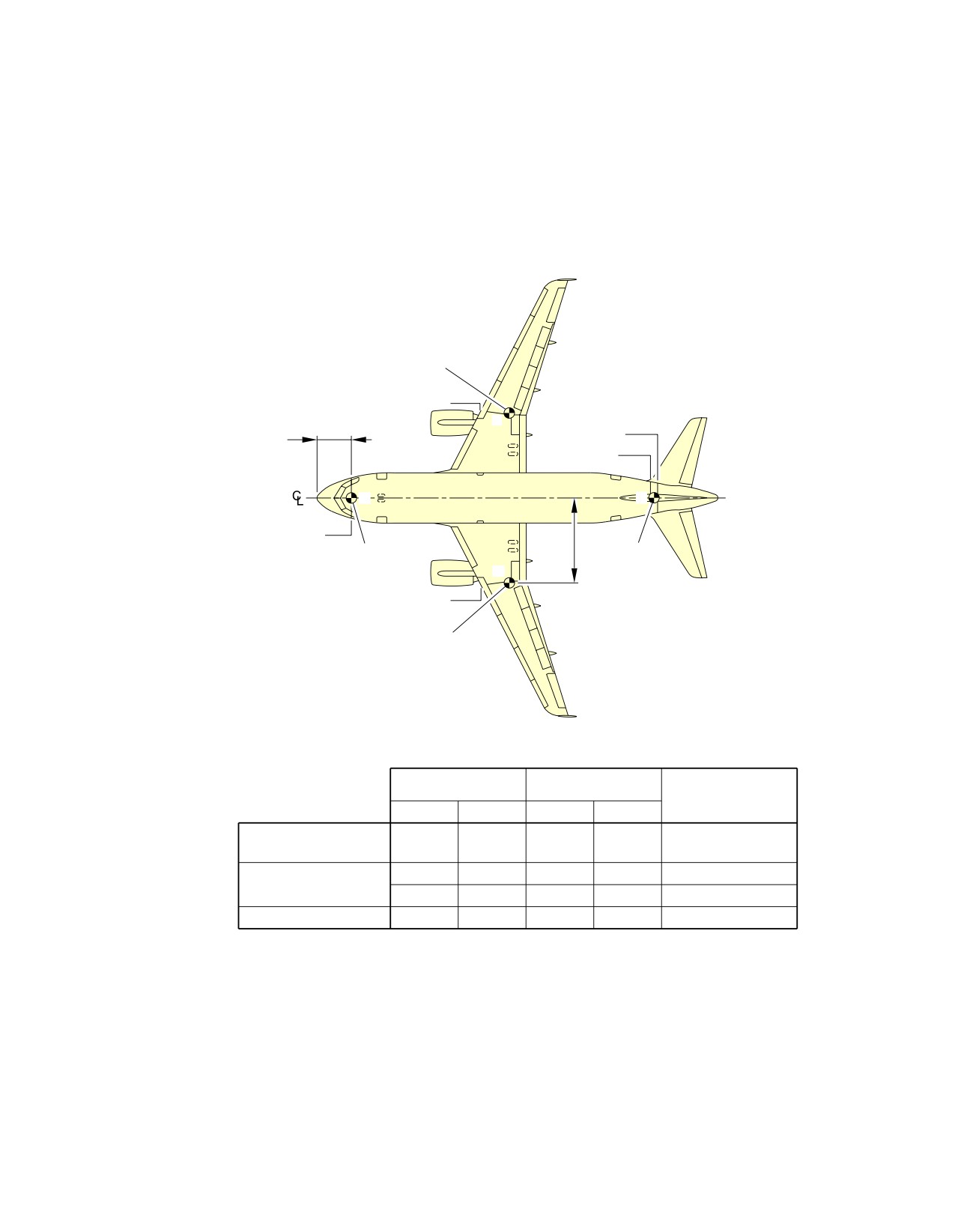
@A318
AIRCRAFT CHARACTERISTICS - AIRPORT AND MAINTENANCE PLANNING
**ON A/C A318-100
WING JACKING
POINT
RIB9
B
FR74
X
FR73
A
C
FR8
Y
FWD JACKING
SAFETY
POINT
STAY
B’
RIB9
WING JACKING
POINT
MAXIMUM
X
Y
LOAD ELIGIBLE
m
ft
m
ft
daN
FORWARD FUSELAGE
2.74
8.99
0
0
6 800
JACKING POINT
A
B
15.18
49.80
6.50
21.33
28 500
WING JACKING
POINT
B’
15.18
49.80
−6.50
−21.33
28 500
SAFETY STAY
C
26.44
86.75
0
0
2 000
NOTE:
SAFETY STAY IS NOT USED FOR JACKING.
N_AC_021400_1_0010101_01_02
Jacking for Maintenance
Jacking Point Locations
FIGURE-2-14-0-991-001-A01
Page 3
May 01/16
2-14-0
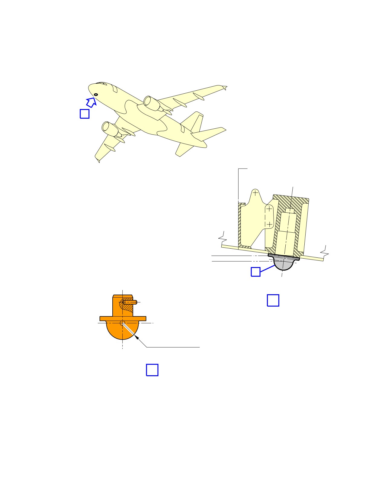
@A318
AIRCRAFT CHARACTERISTICS - AIRPORT AND MAINTENANCE PLANNING
**ON A/C A318-100
A
FR8
POINT A DETAIL
Z−1 979.8
Z−1 987
B
A
SPHERICAL RADIUS
19 mm (0.75 in)
B
N_AC_021400_1_0030101_01_00
Jacking for Maintenance
Forward Jacking Point
FIGURE-2-14-0-991-003-A01
Page 4
May 01/16
2-14-0
//////////////////////////////////////////