Nortel Communication Server 1000. Installation And Commissioning Manual (2008) - page 5

Installing and configuring Nortel IP Phones
Page 401 of 466
NA NEMA 5-15P, 125V 13A (10ft.)
NTTK14AB
Euro CEE (7) VII, 250V, 10A (2.5m)
NTTK16AB
ANZ AS3112, 250V 10A (2.5m)
NTTK15AA
Swiss SEV 1011, 250V 10A (8ft.)
NTTK17AB
UK/Ireland BS1363, 240V 10A (8ft.)
NTTK18AB
Denmark AFSNIT, 250V 10A (2.5m)
NTTK22AB
Argentina IRAM 2073, 250V 10A (8ft.)
A0814961
Table 52 lists the Package components for the WLAN Handsets.
Table 52
WLAN Handset component list (Part 1 of 4)
WLAN Handset 2210 kit North America
NTTQ40AA/A0548444
WLAN Handset 2210 kit Global (power supply not included)
NTTQ40BA/A0548450
North American kit includes:
WLAN 2210 Handset
NTTQ4010/A0548445
WLAN Handset 2210 Battery Pack
NTTQ4050/A0548446
WLAN Handset 2210 Desktop Charger
NTTQ4060/A0548447
WLAN 2210/2211 Charger & Nortel Application Gateway 2246-64
NTTQ4101/A0548449
Power Supply for North America
Global kit is the same as the North American kit without the power
supply
Communication Server 1000E Installation and Commissioning
Page 402 of 466
Installing and configuring Nortel IP Phones
Table 52
WLAN Handset component list (Part 2 of 4)
WLAN Handset 2211 kit North America)
NTTQ50AA/A0548451
WLAN Handset 2211 kit Global (power supply not included
NTTQ50BA/A0548455
North American kit includes:
WLAN 2211 Handset
NTTQ5010/A0548452
WLAN Handset 2211 Battery Pack
NTTQ5050/A0548453
WLAN Handset 2211 Desktop Charger
NTTQ5060/A0548454
WLAN 2210/2211 Charger & WLAN Application Gateway 2246-64
NTTQ4101/A0548449
Power Supply for North America
Global kit is the same as the North American kit without the power
supply
WLAN Handset 2211 Gang Charger
NTTQ5070/A0548039
WLAN Handset 2210 Clothing Clip
NTTQ4080/A0548940
WLAN Handset 2211 Clothing Clip
NTTQ5101/A0548941
WLAN Handset Headset with noise cancellation
NTTQ5501/A0548946
WLAN Handset Headset, over ear
A0548947
WLAN Handset Headset quick disconnect cord
NTTQ5521/A0548948
WLAN Handset 2210/2211 User Guide CD ROM
NTLH21AB/A0548993
WLAN Handset 2211 carrying case, black
NTTQ/5111/A0548942
WLAN Handset 2211 carrying case, (key cover) black
NTTQ5131/A0548944
WLAN Handset 2211 carrying case, yellow
NTTQ5121/A0548943
WLAN Handset 2211 carrying case, (key cover) yellow
NTTQ5141/A0548945
Nortel WLAN IP Telephony Manager 2245, a minimum of one
NTTQ60AA/A048950
Telephony Manager is required per system order
NN43041-310
Standard 01.11
October 2008

Installing and configuring Nortel IP Phones
Page 403 of 466
Table 52
WLAN Handset component list (Part 3 of 4)
WLAN Application Gateway 2246
64 users
NTTQ65AB/N0023211
128 users
NTTQ65BA/A0548971
256 users
NTTQ65CA/A0548972
512 users
NTTQ65DA/A0548973
1,024 users
NTTQ65EA/A0548974
10,000+ users
NTTQ65FA/A0548975
The following items must be ordered with the applicable power supply:
WLAN Handset 2210 Desktop Charger
WLAN Handset 2211 Desktop Charger
WLAN Handset 2211 Gang Charger
WLAN IP Telephony Manager 2245
WLAN Application Gateway 2246 - 64 users
WLAN Application Gateway 2246 - 128 users
WLAN Application Gateway 2246 - 256 users
WLAN Application Gateway 2246 - 512 users
WLAN Application Gateway 2246 - 1024 users
WLAN Application Gateway 2246 - 10,000 users
Communication Server 1000E Installation and Commissioning
Page 404 of 466
Installing and configuring Nortel IP Phones
Table 52
WLAN Handset component list (Part 4 of 4)
Power supplies —
WLAN Handset 2211 Gang Charger:
• North America
NTTQ4301/A0548951
• Europe
NTTQ4311/A0548952
• UK-HK
NTTQ4321/A0548953
• Switzerland
NTTQ4331/A0548954
• Australia-New Zealand
NTTQ4341/A0548955
• Mexico
NTTQ4351
WLAN Handset 2210/2211 Charger & WLAN Application Gateway
2246-64:
NTTQ4101/A0548499
• North America
NTTQ4111/A0548956
• Europe
NTTQ4121/A0548958
• UK-HK
NTTQ4131/A0548959
• Switzerland
NTTQ4141/A0548960
• Australia-New Zealand
NTTQ4151
• Mexico
WLAN IP Telephony Manager 2245 & WLAN Application Gateway
NTTQ4201/A0548961
2246 (128+ users):
NTTQ4211/A0548962
• North America
NTTQ4221/A0548964
• Europe
NTTQ4231/A0548966
• UK-HK
NTTQ4241/A0548967
• Switzerland
NTTQ4251
• Australia-New Zealand
• Mexico
NN43041-310
Standard 01.11
October 2008
Installing and configuring Nortel IP Phones
Page 405 of 466
Connectivity and power requirements
Each Nortel IP Phone requires:
•
a dedicated 10BaseT or 100BaseT or 10/100BaseT Ethernet interface
•
a small desktop hub or switch if sharing an existing desktop Ethernet
connection with a PC.
•
a local power supply appropriate for the voltage in the area or a Power
over LAN unit. (The Nortel IP Phone 2002 comes with a built-in 3-port
switch and is ready for LAN powering.)
Installation and configuration procedures
This chapter contains the following procedures:
•
Procedure 93: "Configuring VoIP bandwidth management zones using
the CLI" on page 406
•
Procedure 94: "Configuring virtual superloops" on page 408
•
Procedure 95: "Configuring the IP Phones" on page 409
•
Procedure 96: "Setting passwords for the administrator and temporary
IP Telephone Installer" on page 414
•
Procedure 97: "Installing Nortel IP Phone hardware components" on
page 417
•
Procedure 98: "Entering IP Telephone boot parameters using manual
configuration" on page 422
•
Procedure 99: "Entering Nortel IP Phone boot parameters using full
DHCP parameters" on page 425
•
Procedure 100: "Entering boot parameters using partial DHCP
parameters" on page 427
•
Procedure 101: "Using Set-Based Installation" on page 430
•
Procedure 102: "Configuring the IP Softphone 2050" on page 433
•
Procedure 103: "Installing the USB Headset Kit" on page 434
•
Procedure 104: "Installing the IP Softphone 2050 on your PC" on
page 434
Communication Server 1000E Installation and Commissioning
Page 406 of 466
Installing and configuring Nortel IP Phones
•
Procedure 105: "Displaying registered IP Phones in Element Manager"
on page 436
Configuring VoIP bandwidth management zones
Follow Procedure 93 to configure the VoIP bandwidth management zones.
For more details on bandwidth management zones, see IP Line: Description,
Installation, and Operation (NN43100-500).
VoIP bandwidth management zones can be configured with Element
Manager or using the CLI. For more information about Element Manager, see
Element Manager: System Administration (NN43001-632).
Procedure 93
Configuring VoIP bandwidth management zones using the CLI
1
Log in to the Call Server.
a. Enter the command:
LOGI
System response:
PASS?
b. Enter the default password:
0000
2
Access LD 117. Enter the command:
LD 117
3
Create a new zone with default parameters. Enter the command:
NEW ZONE 0
Note: LD 117 also includes DIS and ENL commands to disable or enable
a zone. When you create a zone, its default state is enabled. See
Table 53 on page 407 for the LD 117 zone commands.
4
Print zone and bandwidth information. Enter the command:
PRT ZONE.
NN43041-310
Standard 01.11
October 2008
Installing and configuring Nortel IP Phones
Page 407 of 466
5
Exit from LD 117. Enter the command:
****
Table 53
Bandwidth management zones configuration commands in LD 117
Command
Description
NEW ZONE xxx p1 p2 p3 p4 p5
Create a new zone, where:
xxx = zone number = (0) - 255.
p1 = Intrazone available bandwidth
= 0 - (10000) - 100000 (Kbps)
p2 = Intrazone preferred strategy
= (BQ for Best Quality) or BB for Best Bandwidth
p3 = Interzone available bandwidth
= 0 - (10000) - 100000 (Kbps)
p4 = Interzone preferred strategy
= BQ for Best Quality or BB for Best Bandwidth
p5 = Zone resource type
= (shared) or private
NEW ZONE xxx
Create a new zone with default values for the parameters:
p1 = 10000 (Kbps)
p2 = BQ
p3 = 10000 (Kbps)
p4 = BQ
p5 = shared
CHG ZONE xxx p1 p2 p3 p4 p5
Change parameters of a zone. All parameters must be
re-entered, even those that are unchanged.
OUT ZONE xxx
Remove a zone.
DIS ZONE xxx
Disable a zone. When a zone is disabled, no new calls
are established inside, from, or toward this zone.
ENL ZONE xxx
Enable a zone.
PRT ZONE xxx
Print zone and bandwidth information.
Communication Server 1000E Installation and Commissioning
Page 408 of 466
Installing and configuring Nortel IP Phones
End of Procedure
Configuring virtual superloops
Follow Procedure 94 to configure the virtual superloops. For more details on
virtual superloops, see IP Line: Description, Installation, and Operation
(NN43100-500).
Procedure 94
Configuring virtual superloops
1
Access LD 97. Enter the command:
LD 97
2
Enter responses shown in Table 54.
Table 54
LD 97 - Configure a Virtual Superloop.
Prompt
Response
Comment
REQ
CHG
Change existing data
TYPE
SUPL
Superloop
SUPL
Vxxx
V stands for a virtual superloop and xxx is the number of the virtual
superloop.
xxx = 0-252 in multiples of four for MG 1000E
3
Exit from LD 97. Enter the command:
****
End of Procedure
Configuring a Nortel IP Phone using LD 11
Follow Procedure 95 to configure a Nortel IP Phone. The configuration can
be completed using either OTM or CLI.
NN43041-310
Standard 01.11
October 2008

Installing and configuring Nortel IP Phones
Page 409 of 466
Procedure 95
Configuring the IP Phones
1
Access LD 11. Enter the command:
LD 11
2
Enter the appropriate responses shown in Table 55.
Table 55
LD 11 - Configure a Nortel IP Phone (Part 1 of 4)
Prompt
Response
Description
REQ:
NEW CHG
Add new or change existing data
TYPE:
1110
For Nortel IP Phone 1110, Nortel IP Phone 1120E,
1120E
Nortel IP Phone 1140E, Nortel IP Phone 1150E, Nortel
1140E
IP Phone 2001, Nortel IP Phone 2002, Nortel IP Phone
1150E
2004, Nortel IP Phone 2007, Nortel IP Audio Conference
2001
Phone 2033, Nortel IP Softphone 2050.
2002
2004
2007
2033
i2050
TN
Terminal Number
l s c u
Format for CS 1000E, where:
l
= 0, 4, 8, - 252: superloop number in multiples of 4
s = 0-1: MG 1000E on superloop
c = 1-4, 7-10
u = 0-31, (see Table 65 on page 462)
DES
d...d
Office Data Administration System Station Designator
CUST
xx
Customer number as defined in LD 15
ZONE
0-255
Zone number to which this Nortel IP Phone belongs
Communication Server 1000E Installation and Commissioning
Page 410 of 466
Installing and configuring Nortel IP Phones
Table 55
LD 11 - Configure a Nortel IP Phone (Part 2 of 4)
Prompt
Response
Description
CLS
ADD
Class of Service
ADD - Automatic Digit Display, (default for Nortel IP
Phone)
For a complete list of responses, refer to Software Input/
Output: Administration (NN43001-611).
KEY
xx aaa yyyy (cccc or D) zz..z
Telephone function key assignments
The following key assignments determine calling options
and features available to a telephone. Note that KEY is
prompted until just a carriage return <CR> is entered.
xx = key number
aaa = key name or function
yyyy = additional information required for the key
zz..z = additional information required for the key aaa.
The cccc or D entry deals specifically with the Calling
Line identification feature. Where:
cccc = CLID table entry of (0)-N, where N = the value
entered at the SIZE prompt in LD 15 minus 1.
D = the character “D”. When the character “D” is
entered, the system searches the DN keys from key 0
and up, to find a DN key with CLID table entry. The CLID
associated with the found DN key will then be used.
Note: The position of the (cccc or D) field varies depending on
the key name or function.
You may enter a CLID table entry if aaa = ACD, HOT d,
HOT L, MCN, MCR, PVN, PVR, SCN or SCR.
Type xx NUL to remove a key function or feature.
Some data ports require specific key assignments. Refer
to the Meridian Data Services NTPs for information
regarding these requirements.
NN43041-310
Standard 01.11
October 2008
Installing and configuring Nortel IP Phones
Page 411 of 466
Table 55
LD 11 - Configure a Nortel IP Phone (Part 3 of 4)
Prompt
Response
Description
Key number limits that can be assigned are as follows:
0-7 for Meridian Communications Adapter (MCA)
0-5 for M2006
0-7 for M2008
0-59 for M2616, varies with number of add-on
modules
0-79 for I2002, varies with value of KEM
0-79 for I2004, varies with value of KEM
Note: The first Nortel IP Phone KEM is assigned keys 32-55,
and the second Nortel IP Phone KEM is assigned keys 56-79.
Type xx = NUL to remove a key function or feature for
i2002 and i2004.
If either the Meridian Programmable Data Adapter
(MPDA) or the Display Module is equipped, then key 7
on sets M2008, M2216, and M2616 sets and key 5 on
set M2006 will become Program keys which cannot be
used as function keys.
Any printout of the TN block will not show key 7 because
it is a local function key.
On the M2616, if CLS = HFA, key 15 on the voice TN
defaults to the Handsfree key. No other feature
assignment is accepted.
Primary and secondary data DNs must be unique.
A station SCR, SCN, MCR, or MCN DN must be
removed as a member from all Group Hunt lists before
the DN can be modified.
Communication Server 1000E Installation and Commissioning
Page 412 of 466
Installing and configuring Nortel IP Phones
Table 55
LD 11 - Configure a Nortel IP Phone (Part 4 of 4)
Prompt
Response
Description
On the M3903, keys 4-15 are blocked. No feature
assignment is accepted for keys 2-15.
On the M3903, M3904, and M3905, keys 29-31 are
reserved. No feature assignment is accepted for keys
29-31 other than NUL.
On M3904, no feature assignment is accepted for keys
12-15.
On M3905, the technician can assign NUL or a server
application on key 5. On key 6, the craftsperson can
assign NUL or a local application.
On M3905, the technician can assign NUL or the
program key on key 7.
On M3905, the technician can assign AAG, AMG,
ASP,DWC, EMR, MSB, or NRD on keys 8-11. Other
features are blocked.
For Nortel IP Phones:
xx = Keys 0-5 (and 6-11 using Shift key). These are
self-labeled physical keys that can be programmed with
any feature.
Note 1: The Nortel IP Phone 2002 does not have a Shift
key. Only keys 0-3 can be programmed.
Note 2: Keys 16-26 are reserved for dedicated Nortel IP
Phone soft keys.
Table 56 on page 413 lists the dedicated Nortel IP
Phone key name values (aaa). Other key name values
can be found in Software Input/Output: Administration
(NN43001-611).
NN43041-310
Standard 01.11
October 2008
Installing and configuring Nortel IP Phones
Page 413 of 466
3
Configure the dedicated soft keys, as shown in Table 56.
Table 56
Nortel IP Phone dedicated soft key assignment (Part 1 of 2)
Nortel IP Phone key
number
Response(s) Allowed
Key 16
MWK, NUL
MWK - Message Waiting key
Key 17
TRN, NUL
TRN - Call Transfer key
Key 18
A03 or A06, NUL
AO3 - 3-party conference key
AO6 - 6-party conference key
Key 19
CFW, NUL
CFW - Call Forward key
Key 20
RGA, NUL
RGA - Ring Again key
Key 21
PRK, NUL
PRK - Call Park key
Key 22
RNP, NUL
RNP - Ringing Number pickup key
Key 23
SCU - Speed Call User
SSU - System Speed Call User
SCC - Speed Call Controller
SSC - System Speed Call Controller
NUL
Key 24
PRS, NUL
PRS - Privacy Release key
Communication Server 1000E Installation and Commissioning
Page 414 of 466
Installing and configuring Nortel IP Phones
Table 56
Nortel IP Phone dedicated soft key assignment (Part 2 of 2)
Nortel IP Phone key
number
Response(s) Allowed
Key 25
CHG, NUL
CHG - Charge Account key
Key 26
CPN, NUL
CPN - Calling Party Number key
4
Repeat Steps 2 and 3 for each Nortel IP Phone.
End of Procedure
Setting administrator and temporary IP Telephone
Installer passwords
Nortel IP Phone Installer Passwords is an optional feature that provides
protection against unauthorized modification of the TN on the IP Phones. For
detailed information about the Nortel IP Phone Installer Passwords, see
IP Line: Description, Installation, and Operation (NN43100-500).
The Nortel IP Phone Installer Passwords are configured on either a Signaling
Server or a Media Card in a node. The passwords then apply to all
components in the node.
Procedure 96
Setting passwords for the administrator and temporary
IP Telephone Installer
Note: This procedure can also be performed from the CLI of a Signaling
Server or Media Card.
1
Log in to Element Manager.
2
Select INetwork > Maintenance and Reports from the navigator.
The Node Maintenance and Reports web page opens, as shown in
Figure 143 on page 337.
NN43041-310
Standard 01.11
October 2008
Installing and configuring Nortel IP Phones
Page 415 of 466
3
Click the desired node to expand it.
4
Click GEN CMD for the chosen Signaling Server or Media Card.
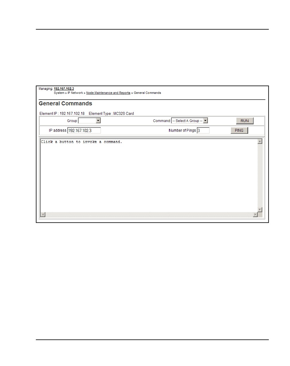
The General Commands web page opens, as shown in Figure 173.
Figure 173
General Commands
5
Select NodePwd from the Group drop-down list.
6
Select nodePwdShow from the Command drop-down list.
7
Click RUN.
The current node password information displays in the text area at the
bottom of the web page.
8
Select nodePwdSet from the drop-down list.
Communication Server 1000E Installation and Commissioning
Page 416 of 466
Installing and configuring Nortel IP Phones
9
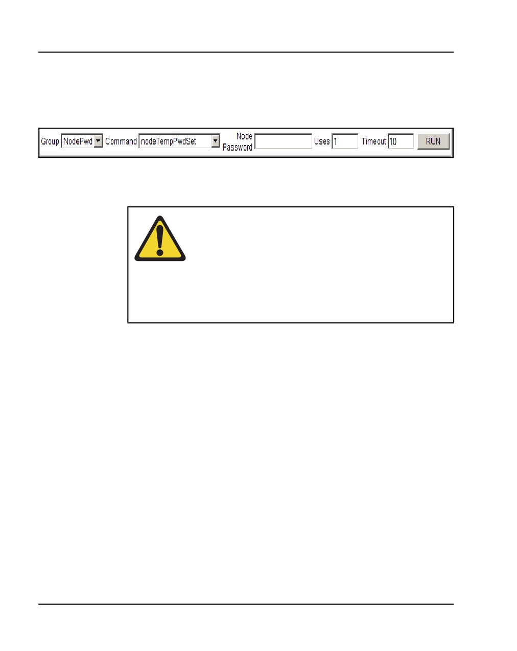
Enter the administrator Nortel IP Phone Installer Password in the Node
Password box (see Figure 174).
Figure 174
Node Password
Note: The entered password appears as asterisks. The valid characters
are 0-9 * #. The password can be null or 6 to 14 digits in length.
WARNING
If the administrator password is null (zero length), then
the Node ID, TN, and Password screens are not
displayed on the IP Phones during their registration
process. This provides security as it prevents any entry
of passwords or TNs on the IP Phones. However, it is
impossible to install new IP Phones (unless a temporary
password is set).
10
Select NodePwd from the Group drop-down list.
11
Select nodePwdShow from the Command drop-down list.
12
Click RUN.
The updated administrator Nortel IP Phone Installer Password is
displayed in the text area at the bottom of the web page.
13
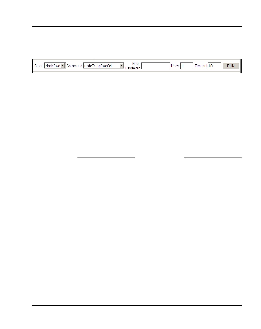
Enter the temporary Nortel IP Phone Installer Password (see
Figure 175):
a. Enter the password in the Node Password text box.
b. Select NodePwd from the Group drop-down list.
c. Select nodeTempPwdSet from the Command drop-down list.
The area then displays the Uses and Timeout text boxes.
d. Enter a value for the number of uses or a value for timeout (in hours)
or both.
14
Click SET.
NN43041-310
Standard 01.11
October 2008
Installing and configuring Nortel IP Phones
Page 417 of 466
The temporary password is set.
Figure 175
Node Temp Password
Note 1: The entered password appears as asterisks. The valid
characters are 0-9 * #. The password can be 6 to 14 digits in length.
Note 2: The temporary password automatically deletes itself after it has
been used the defined number of times or when the duration expires,
whichever comes first.
15
Select NodePwd from the Group drop-down list.
16
Select the nodePwdShow command from the Command drop-down list.
17
Click RUN.
The updated temporary Nortel IP Phone Installer Password is displayed.
End of Procedure
Installing Nortel IP Phone hardware components
Follow Procedure 97 to install Nortel IP Phone hardware components.
Procedure 97
Installing Nortel IP Phone hardware components
For details on installing hardware components, see IP Phones: Description,
Installation, and Operation (NN43001-368).
1
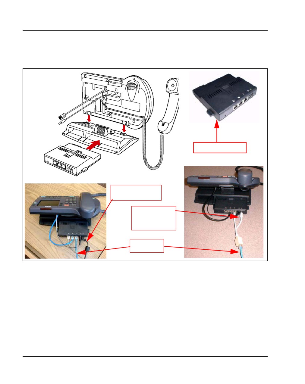
Refer to Figure 176 on page 418, when installing the following:
a. Footstand
b.
3-Port Switch only on the Nortel IP Phone 2004, required if a single
Ethernet connection is shared with a PC
c. Ethernet cable from the set to the 3-Port Switch
d. Power Transformer or Power Splitter for Power over LAN unit
e. Handset
Communication Server 1000E Installation and Commissioning
Page 418 of 466
Installing and configuring Nortel IP Phones
f.
Handset cord
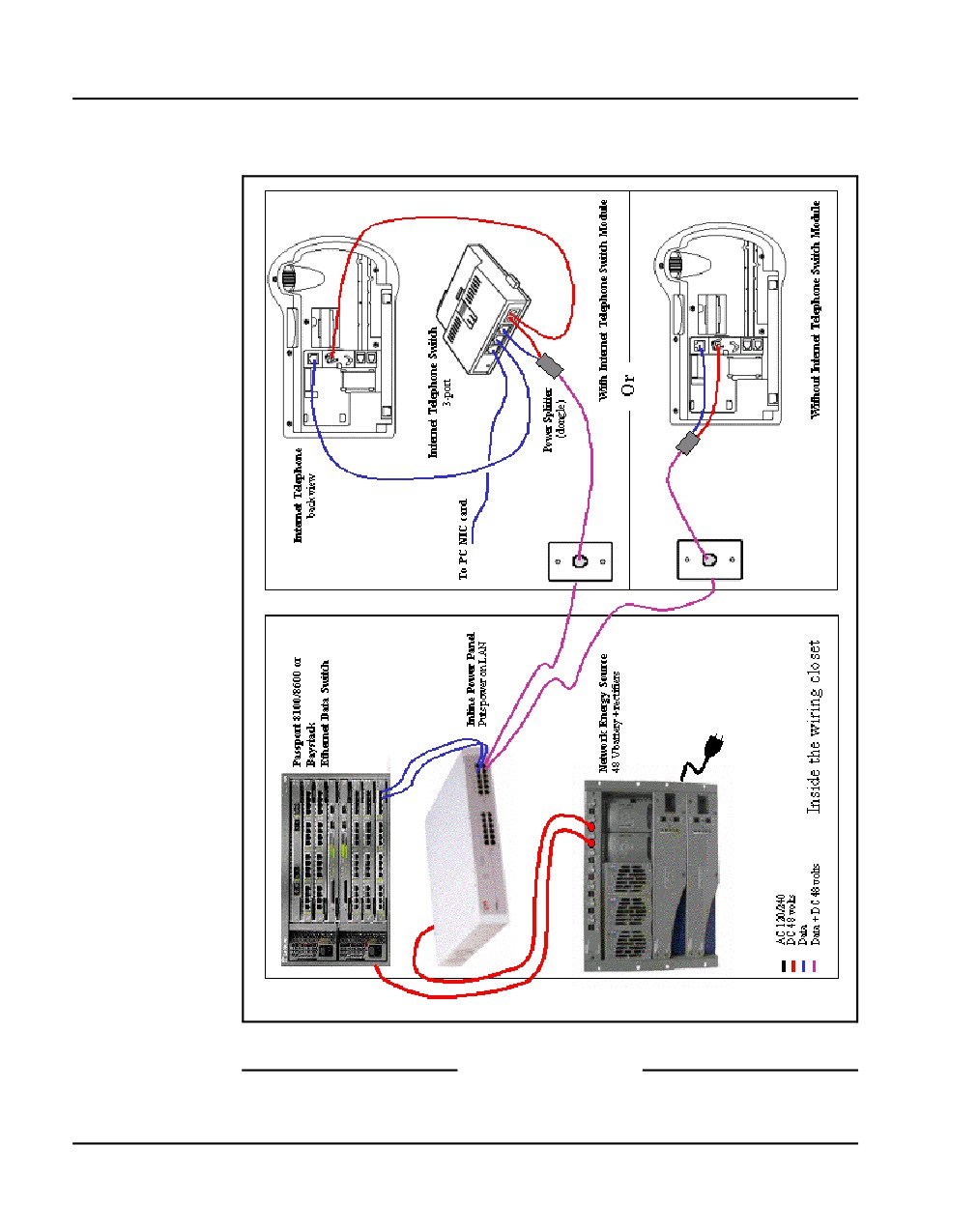
Figure 176
Nortel IP Phone 2004 components
Three Port Switch
Power Transformer
connection
Power Splitter
connection
(power over LAN)
CAT5 line
cable
NN43041-310
Standard 01.11
October 2008
Installing and configuring Nortel IP Phones
Page 419 of 466
2
Connect one end of the CAT5 line cable to the Ethernet jack at the back
of the telephone. See Figure 176 on page 418.
3
Connect the other end into the IP voice network (Ethernet), using an
RJ-45 connector. See Figure 177 on page 420.
WARNING
Do not plug the Nortel IP Phone into an ISDN
connection. Severe damage can result. Consult the
system administrator to ensure that the telephone is
being plugged in to a 10/100BaseT Ethernet jack.
4
Power the Nortel IP Phone with one of the following methods:
a. Using a 16V AC power adaptor, plug the AC power transformer into
the nearest power outlet. Check the Nortel IP Phone User Guide for
country-specific parameters.
b. Using a Power over LAN unit, connect the Power over LAN unit as
shown in Figure 177 on page 420.
5
Secure the telephone footstand to the base of the telephone. Use the
angle adjustment grip on the top rear of the telephone to adjust the
position.
Communication Server 1000E Installation and Commissioning
Page 420 of 466
Installing and configuring Nortel IP Phones
Figure 177
Nortel IP Phone connections
End of Procedure
NN43041-310
Standard 01.11
October 2008
Installing and configuring Nortel IP Phones
Page 421 of 466
Configuring the Nortel IP Phone boot parameters
The Nortel IP Phone boot parameters are configured during telephone
installation. The following configuration modes are available:
•
Manual configuration
— All of the Nortel IP Phone's boot parameters are statically
configured at the Nortel IP Phone.
— See Procedure 98: "Entering IP Telephone boot parameters using
manual configuration" on page 422.
•
Partial Dynamic Host Configuration Protocol (DHCP) mode
— Works with standard DHCP server. The DHCP server automatically
provides the Nortel IP Phone with an IP address; the remainder of
the Nortel IP Phone's boot parameters are statically configured at the
Nortel IP Phone.
— See Procedure 99: "Entering Nortel IP Phone boot parameters using
full DHCP parameters" on page 425.
•
Full DHCP mode
— Requires special configuration of the DHCP server to recognize the
Nortel IP Phone. The DHCP server provides all boot parameters to
the Nortel IP Phone, including IP address and server address.
— See Procedure 100: "Entering boot parameters using partial DHCP
parameters" on page 427.
For configuration of the DHCP server, see Converging the Data Network with
VoIP (NN43001-260).
Communication Server 1000E Installation and Commissioning
Page 422 of 466
Installing and configuring Nortel IP Phones
Entering Nortel IP Phone boot parameters
using manual configuration
Follow Procedure 98 to enter IP Telephone boot parameters using manual
configuration.
Procedure 98
Entering IP Telephone boot parameters using manual configuration
1
Power the Nortel IP Phone.
Within four seconds, the Nortel logo appears.
2
When the Nortel logo appears on the display, you have one second to
press the four feature keys at the bottom of the display in sequence, from
left to right.
Note: If the Nortel logo times out, repeat step 1 and step 2.
3
For the following prompts:
a. Press the BKSpace (backspace) or Clear keys to change an entry.
b. Enter new values using the telephone’s keypad.
c. Press the OK key to accept your selection.
The Nortel IP Phone prompts:
DHCP? (0-No, 1-Yes): 0
4
Enter 0 for manual boot parameter configuration.
The Nortel IP Phone prompts:
SET IP: x.x.x.x
5
Enter the Nortel IP Phone IP address.
The Nortel IP Phone prompts:
NETMSK: x.x.x.x
6
Enter the subnet mask.
The Nortel IP Phone prompts:
DEF GW: x.x.x.x
NN43041-310
Standard 01.11
October 2008
Installing and configuring Nortel IP Phones
Page 423 of 466
7
Enter the default gateway.
The Nortel IP Phone prompts:
S1 IP: x.x.x.x
8
Enter the Server 1 IP (node IP).
The Nortel IP Phone prompts:
S1 PORT: 4100
9
Enter the Server 1 port.
The Nortel IP Phone prompts:
S1 ACTION: 1
10
Enter the Server 1 action.
The Nortel IP Phone prompts:
S1 RETRY COUNT: 10
11
Enter the Server 1 retry count.
The Nortel IP Phone prompts:
S2 ...
12
Enter same information as for Server 1.
The Nortel IP Phone prompts:
VLAN?(0-No,1-Ma,2-Au)0
13
Choose one of the following:
a. Enter 0 to configure no VLAN.
The Nortel IP Phone displays:
Locating server...
After several seconds, the Nortel IP Phone prompts:
Connect Svc
Node: x
TN: x.x
Go to step 14 on page 424.
Communication Server 1000E Installation and Commissioning
Page 424 of 466
Installing and configuring Nortel IP Phones
b. Enter 1 to configure manual VLAN.
The Nortel IP Phone prompts:
VLAN: x
Go to step 14 on page 424.
c. Press the OK key.
The Nortel IP Phone prompts:
Invalid TN: x.x
Reason: Unequipped.
Go offhook to do SBI
14
Enter the VLAN ID.
The Nortel IP Phone displays:
Locating server...
If you did not configure an Nortel IP Phone Installer Password, after
several seconds, the Nortel IP Phone prompts:
Node: x
TN: x.x
15
Enter the node number and the Nortel IP Phone's (virtual) TN, then go to
Step 18.
If you configured an Nortel IP Phone Installer Password, the Nortel IP
Phone prompts:
Node: x
PassWord: x
16
Enter the node number and the temporary or administrator Nortel IP
Phone Installer Password.
Note 1: An asterisk is displayed for each password digit entered; the
actual password is not displayed.
Note 2: If this screen times out, or if you do not successfully enter the
password in three attempts, the Nortel IP Phone continues its registration
process as if no entry had been made to this prompt. You can reboot the
telephone and try again if more tries are needed.
The Nortel IP Phone prompts:
TN: x.x
NN43041-310
Standard 01.11
October 2008
Installing and configuring Nortel IP Phones
Page 425 of 466
17
Enter the Nortel IP Phone’s (virtual) TN.
The Nortel IP Phone displays the logo, the date and time, and the DN
keys.
18
Check for dial tone and the correct DN above the display.
End of Procedure
Entering Nortel IP Phone boot parameters
using full DHCP parameters
Follow Procedure 99 to enter IP Phone boot parameters using full DHCP
parameters.
Procedure 99
Entering Nortel IP Phone boot parameters using full DHCP parameters
1
Power the Nortel IP Phone.
Within four seconds, the Nortel logo appears.
2
When the Nortel logo appears on the display, you have one second to
press the four feature keys at the bottom of the display in sequence, from
left to right.
Note: If the Nortel logo times out, repeat step 1 and step 2.
3
For the following prompts:
a. Press the BKSpace (backspace) or Clear keys to change an entry.
b. Enter new values using the telephone’s keypad.
c. Press the OK key to accept your selection.
The Nortel IP Phone prompts:
DHCP? (0-No, 1-Yes): 0
4
Enter 1 to use DHCP.
The Nortel IP Phone prompts:
DHCP:0-Full, 1-Partial:0
5
Enter the 0 to use Full DHCP.
The Nortel IP Phone prompts:
Communication Server 1000E Installation and Commissioning
Page 426 of 466
Installing and configuring Nortel IP Phones
VLAN?(0-No,1-Ma,2-Au)0
6
Choose one of the following:
a.
Enter 0 to configure no VLAN.
The Nortel IP Phone displays:
Locating server...
After several seconds, the Nortel IP Phone prompts:
Connect Svc
Node: x
TN: x.x
Go to step 7 on page 426.
b.
Enter 1 to configure manual VLAN.
The Nortel IP Phone prompts:
VLAN: x
Go to step 7.
c.
Enter 2 to configure automatic VLAN.
The Nortel IP Phone prompts:
VLAN: x
Go to step 7
7
Enter the VLAN ID.
The Nortel IP Phone displays:
Locating server...
If you did not configure an Nortel IP Phone Installer Password, after
several seconds, the Nortel IP Phone prompts:
Node: x
TN: x.x
8
Enter the node number and the Nortel IP Phone's (virtual) TN, and then
go to step 11 on page 427.
If you configured an Nortel IP Phone Installer Password, the Nortel IP
Phone prompts:
Node: x
PassWord: 0
NN43041-310
Standard 01.11
October 2008
Installing and configuring Nortel IP Phones
Page 427 of 466
9
Enter the node number and the temporary or administrator Nortel IP
Phone Installer Password.
Note 1: An asterisk is displayed for each password digit entered; the
actual password is not displayed.
Note 2: If this screen times out, or if you do not successfully enter the
password in three attempts, the Nortel IP Phone continues its registration
process as if no entry had been made to this prompt. You can reboot the
telephone and try again if more tries are needed.
The Nortel IP Phone prompts:
TN: x.x
10
Enter the Nortel IP Phone’s (virtual) TN.
The Nortel IP Phone displays the logo, the date and time, and the DN
keys.
11
Check for dial tone and the correct DN above the display.
End of Procedure
Entering boot parameters using partial DHCP parameters
Follow Procedure 100 to enter IP Telephone boot parameters using partial
DHCP parameters.
Procedure 100
Entering boot parameters using partial DHCP parameters
1
Power up the Nortel IP Phone.
Within four seconds, the Nortel logo appears.
2
When the Nortel logo appears on the display, you have one second to
press the four feature keys at the bottom of the display in sequence, from
left to right.
Note: If the Nortel logo times out, repeat step 1 and step 2.
3
For the following prompts:
a. Press the BKSpace (backspace) or Clear keys to change an entry.
b. Enter new values using the telephone’s keypad.
Communication Server 1000E Installation and Commissioning
Page 428 of 466
Installing and configuring Nortel IP Phones
c. Press the OK key to accept your selection.
The Nortel IP Phone prompts:
DHCP? (0-No, 1-Yes): 0
4
Enter 1 to use DHCP.
The Nortel IP Phone prompts:
DHCP:0-Full, 1-Partial:0
5
Enter the 1 to use Partial DHCP.
The Nortel IP Phone prompts:
S1 IP: x.x.x.x
6
Enter the Server 1 IP (node IP).
The Nortel IP Phone prompts:
S1 PORT: 4100
7
Enter the Server 1 port.
The Nortel IP Phone prompts:
S1 ACTION: 1
8
Enter the Server 1 action.
The Nortel IP Phone prompts:
S1 RETRY COUNT: 10
9
Enter the Server 1 retry count.
The Nortel IP Phone prompts:
S2 ...
10
Enter same information as for Server 1.
The Nortel IP Phone prompts:
VLAN?(0-No,1-Ma,2-Au)0
NN43041-310
Standard 01.11
October 2008
Installing and configuring Nortel IP Phones
Page 429 of 466
11
Choose one of the following:
a.
Enter 0 to configure no VLAN.
The Nortel IP Phone displays:
Locating server...
After several seconds, the Nortel IP Phone prompts:
Connect Svc
Node: x
TN: x.x
Go to step 12.
b.
Enter 1 to configure manual VLAN.
The Nortel IP Phone prompts:
VLAN: x
Go to step 12 on page 429.
c.
Enter 2 to configure automatic VLAN.
The Nortel IP Phone prompts:
VLAN: x
Go to step 12.
12
Enter the VLAN ID.
The Nortel IP Phone displays:
Locating server...
If you did not configure an Nortel IP Phone Installer Password, after
several seconds, the Nortel IP Phone prompts:
Node: x
TN: x.x
13
Enter the node number and the Nortel IP Phone's (virtual) TN then go to
step 16.
If you configured a Nortel IP Phone Installer Password, the Nortel IP
Phone prompts:
Node: x
PassWord: 0
Communication Server 1000E Installation and Commissioning
Page 430 of 466
Installing and configuring Nortel IP Phones
14
Enter the node number and the temporary or administrator Nortel IP
Phone Installer Password.
Note 1: An asterisk is displayed for each password digit entered; the
actual password is not displayed.
Note 2: If this screen times out, or if you do not successfully enter the
password in three attempts, the Nortel IP Phone continues its registration
process as if no entry had been made to this prompt. You can reboot the
telephone and try again if more tries are needed.
The Nortel IP Phone prompts:
TN: x.x
15
Enter the Nortel IP Phone’s (virtual) TN.
The Nortel IP Phone displays the logo, the date and time, and the DN
keys.
16
Check for dial tone and the correct DN above the display.
End of Procedure
Using Set-Based Installation
Set-Based Installation enables the delegation of telephone installation to
trusted users. To have a trusted user perform this function, configure a
temporary Nortel IP Phone Installer Password for the system. See “Setting
administrator and temporary IP Telephone Installer passwords” on page 414.
Note: This feature can be an alternative to LD 11 or TM to configure
IP Phones on the Call Server.
Follow Procedure 101 to use Set-Based Installation.
Procedure 101
Using Set-Based Installation
This procedure is the same as Procedure 98 on page 422, Procedure 99 on
page 425, and Procedure 100 on page 427, except when the system
response, displayed on the Nortel IP Phone, is as follows:
If you did not configure an Nortel IP Phone Installer Password, the Nortel IP
Phone prompts:
NN43041-310
Standard 01.11
October 2008
Installing and configuring Nortel IP Phones
Page 431 of 466
Node: x
TN: x.x
1
Enter the node number and the Nortel IP Phone's (virtual) TN, then go to
Step 4.
If you configured a Nortel IP Phone Installer Password, the Nortel IP
Phone prompts:
Node: x
PassWord: 0
2
Enter the node number and the temporary or administrator Nortel IP
Phone Installer Password.
Note 1: An asterisk is displayed for each password digit entered; the
actual password is not displayed.
Note 2: If this screen times-out, or if you do not successfully enter the
password in 3 attempts, the Nortel IP Phone continues its registration
process as if no entry had been made to this prompt. You can reboot the
telephone and try again if more tries are needed.
The Nortel IP Phone prompts:
TN: x.x
3
Enter the Nortel IP Phone’s (virtual) TN.
4
Press the OK key.
The Nortel IP Phone responds Unequipped...
5
Lift the handset. The system accepts the TN.
6
Listen for the continuous dial tone.
The system response, displayed on the Nortel IP Phone, is as follows:
Model ? (20)
7
Press the # key to select the default model, or enter the model number
and press #.
8
Listen for a special tone.
The system response, displayed on the Nortel IP Phone, is as follows:
OK, ZONE? (0)
9
Press the # key to select the default zone, or enter the zone number and
press #.
Communication Server 1000E Installation and Commissioning
Page 432 of 466
Installing and configuring Nortel IP Phones
The system response, displayed on the Nortel IP Phone, is as follows:
OK, EXTENSION? 2244
10
Press the # key to select the default DN, or enter a DN and press #.
11
Listen for a relocation tone.
The system response, displayed on the Nortel IP Phone, is as follows:
OK
12
Replace the handset.
The set displays the logo, the date and time, and the DN keys The set
based installation is complete.
End of Procedure
Installing the IP Softphone 2050
This chapter contains the following procedures:
•
Procedure 102: "Configuring the IP Softphone 2050" on page 433
•
Procedure 103: "Installing the USB Headset Kit" on page 434
•
Procedure 104: "Installing the IP Softphone 2050 on your PC" on
page 434
•
“Running the IP Softphone 2050 for the first time” on page 435
NN43041-310
Standard 01.11
October 2008
Installing and configuring Nortel IP Phones
Page 433 of 466
Procedure 102
Configuring the IP Softphone 2050
1
Access LD 11. Enter the command:
LD 11
2
Enter appropriate responses shown in Table 57.
Table 57
LD 11 - Configure the IP Softphone 2050
Prompt
Response
Description
REQ:
NEW
Add new data
CHG
Change existing data
TYPE:
I2050pc
Type of data block
TN
l s c u
Terminal number
DES
x...x
ODAS telephone designator
CUST
xx
Customer number, as defined in LD 15
ZONE
0-255
Zone number
FDN
x...x
Flexible CFNA DN
CLS
aaa
Class of service
HFA - Digital Telephone Handsfree Allowed is default for IP
Softphone 2050 to enable the USB interface
End of Procedure
Installing and configuring on the PC
Installing the USB Headset Kit
Installing the USB Headset Kit application after the IP Softphone 2050
software application enables the IP Softphone 2050 application to show it as
an audio device option during the installation. If the USB Headset Kit is
Communication Server 1000E Installation and Commissioning
Page 434 of 466
Installing and configuring Nortel IP Phones
installed, you can still choose it as the audio device from the Configuration
Utility.
Procedure 103
Installing the USB Headset Kit
1
Connect the coiled lower cord to the headset cord with the Quick
Disconnect connector. Ensure the Quick Disconnect is securely fastened.
2
Connect the headset cord to the RJ9 jack on the adaptor.
3
Connect the USB cable to the headset adaptor and to one of the USB
jacks at the back of your PC or USB hub.
End of Procedure
The first time the headset adapter is plugged in, there is a delay while
Windows ® configures the device and locates appropriate driver software.
During the installation you can be prompted to supply the original Windows
CD-ROM so that Windows can locate the required drivers.
Installing the IP Softphone 2050 application
Procedure 104
Installing the IP Softphone 2050 on your PC
1
Insert the CD-ROM disk into the CD-ROM drive of your PC.
Note: Installation should proceed automatically. If it does not, then
continue with step 1. Otherwise go directly to step 5.
2
On the PC desktop, double-click the My Computer icon.
3
Double-click the CD icon.
4
Double-click the Setup icon.
5
Follow the prompts that appear on the screen.
6
Run the IP Softphone 2050 Configuration Utility to assign a server
address, select sound devices, and select a server type.
End of Procedure
NN43041-310
Standard 01.11
October 2008
Installing and configuring Nortel IP Phones
Page 435 of 466
Running the IP Softphone 2050 for the first time
Installation places the IP Softphone 2050 in the Windows Start menu at Start
> Programs > Nortel > IP Softphone 2050. The Configuration Utility is
placed in the Windows Control Panel.
The IP Softphone 2050 application is started by one of the following:
•
Select Start > Programs > Nortel > IP Softphone 2050.
•
Click the desktop shortcut (if one was created during the installation).
•
Automatic start-up sequence.
Note: If you want the IP Softphone 2050 to start automatically when the
PC boots, place a shortcut to the application in the Start-up folder.
When an IP Softphone 2050 starts for the first time and connects to the
network, it executes a start-up sequence. The elements of the start-up
sequence are as follows:
•
Get the IP parameters.
•
Find a gateway server, and authenticate the user.
As the IP Softphone 2050 registers with the system, the following occurs:
•
If a non-null node password is enabled, it prompts for a node number and
password. Enter the node number and password using the keyboard or
numeric keypad. After the password is verified, enter the TN of the IP
Softphone 2050. See IP Line: Description, Installation, and Operation
(NN43100-500) for more on the password feature.
•
If the null node password is configured and enabled, these screens are
skipped and no option is provided to change the password.
•
If the node password is disabled or not configured, it prompts for a node
number and TN. Enter the node number and TN using the keyboard or
numeric keypad.
The IP Softphone 2050 configuration is complete.
Communication Server 1000E Installation and Commissioning
Page 436 of 466
Installing and configuring Nortel IP Phones
Verifying Nortel IP Phone functionality
You can now use the IP Phones. To test the telephones, make Nortel IP
Phone-to-Nortel IP Phone calls.
Displaying registered IP Phones
Follow Procedure 105 to display the IP Phones registered on a Signaling
Server or Voice Gateway Media Card.
Procedure 105
Displaying registered IP Phones in Element Manager
1
Log in to Element Manager.
2
Select System > IP Network > Maintenance and Reports from the
navigator.
3
Click the desired node to expand it.
4
Click GEN CMD for the desired Signaling Server or Media Card.
a. Select Iset from the Group Drop Down List box.
b. If prompted, select the range of sets to display.
c. Click RUN.
The status of all IP Phones registered on this Signaling Server or Media Card
is displayed.
End of Procedure
Upgrading firmware
Refer to the IP Line: Description, Installation, and Operation
(NN43100-500), to check for the latest Nortel IP Phone firmware version and
how to upgrade to the latest Nortel IP Phone firmware.
NN43041-310
Standard 01.11
October 2008
450
Page 437 of 466
Installing and cross-connecting a
Power Fail Transfer Unit
Contents
This section contains information on the following topics:
Introduction
437
Installing and connecting a QUA6 PFTU
438
Installing and connecting a third-party PFTU
443
Connecting an analog (500/2500-type) telephone to a PFTU
444
Connecting a trunk to a PFTU
448
Introduction
Power fail transfer occurs when the main power to the CS 1000E system is
cut off. When a power interruption occurs, the Power Fail Transfer Unit
(PFTU) connects predetermined analog (500/2500-type) telephones directly
to the Central Office trunks. A PFTU is capable of supporting a maximum of
five or eight telephones (depending on the PFTU type).
A PFTU can be connected to the AUX connector on a Media Gateway.
IMPORTANT!
A PFTU does not support Digital trunks. Use Analog trunks if power
failure backup is required.
Communication Server 1000E Installation and Commissioning
Page 438 of 466
Installing and cross-connecting a Power Fail Transfer Unit
The following procedures are provided in this chapter:
1
Procedure 106: "Installing and connecting a QUA6 PFTU" on page 438
2
Procedure 107: "Connecting an analog (500/2500-type) telephone to a
PFTU" on page 446
3
Procedure 108: "Connecting a Trunk to a PFTU" on page 448
Installing and connecting a QUA6 PFTU
Follow Procedure 106 to install and connect a QUA6 PFTU. Refer to the
equipment layout plan for the location of the PFTU.
Note: The QUA6 PFTU operates with loop-start and ground-start
Central Office trunks. With ground start trunks, the associated telephone
set must have a ground start button.
Procedure 106
Installing and connecting a QUA6 PFTU
1
Install the PFTU on the wall near the system cross-connect terminal.
Fasten the PFTU in position with four screws.
2
Install an NE-A25B-type 25-pair cable from connector J1 on the faceplate
of the PFTU to its assigned location at the cross-connect terminal.
3
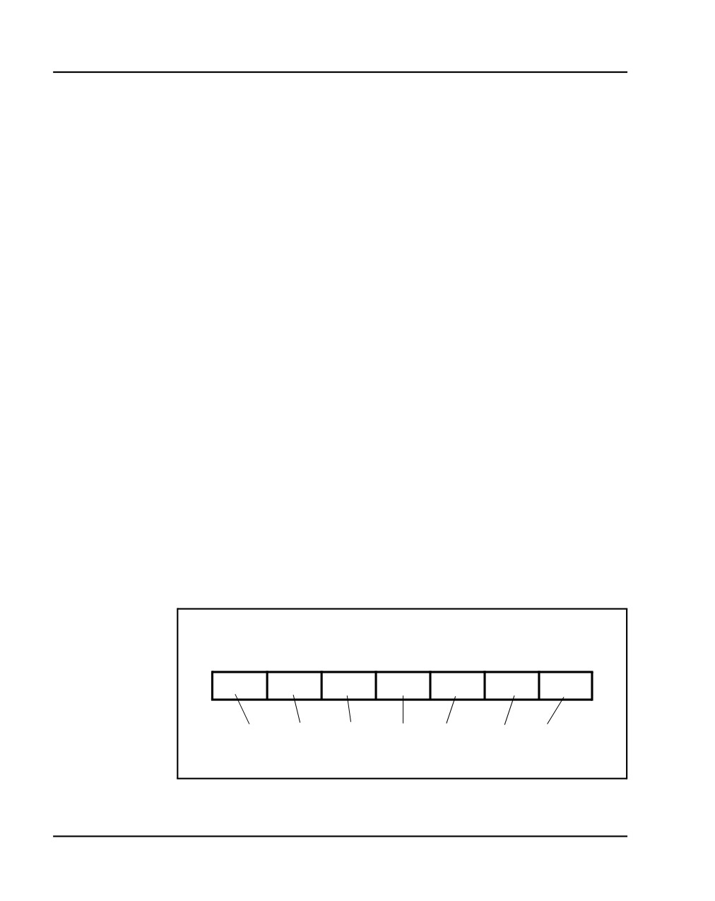
Label the pairs of the J1 cable on the cross-connect terminal block as
shown in Figure 178 on page 438.
Figure 178
J1 cable labels
Pairs
Pairs
Pairs
Pairs
Pairs
Pairs Pairs
1 to 4
1 to 4
1 to 4
1 to 4
1 to 4
1 to 4
1 to 4
PFT1
Control
PFT1
PFT2
PFT3
PFT4
PFT5
Power
Label the pairs on the terminal block as shown. If using
BIX blocks, attach the appropriate designation strip.
NN43041-310
Standard 01.11
October 2008
Installing and cross-connecting a Power Fail Transfer Unit
Page 439 of 466
4
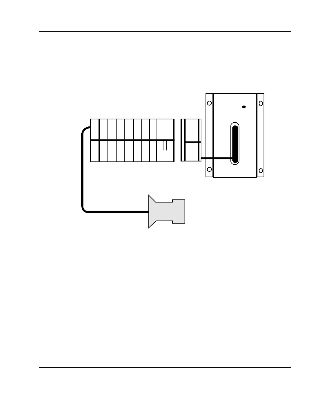
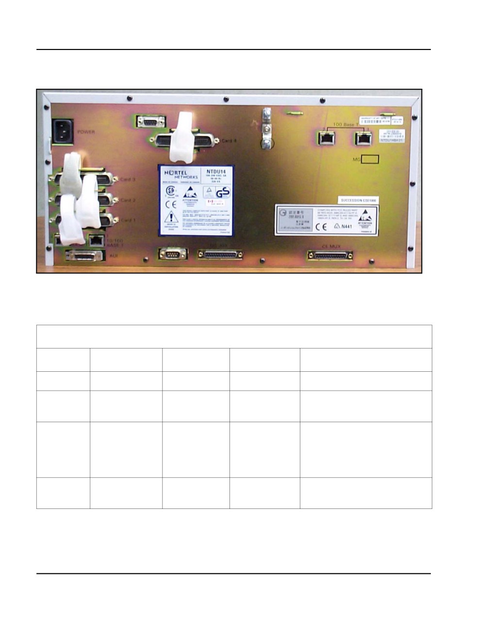
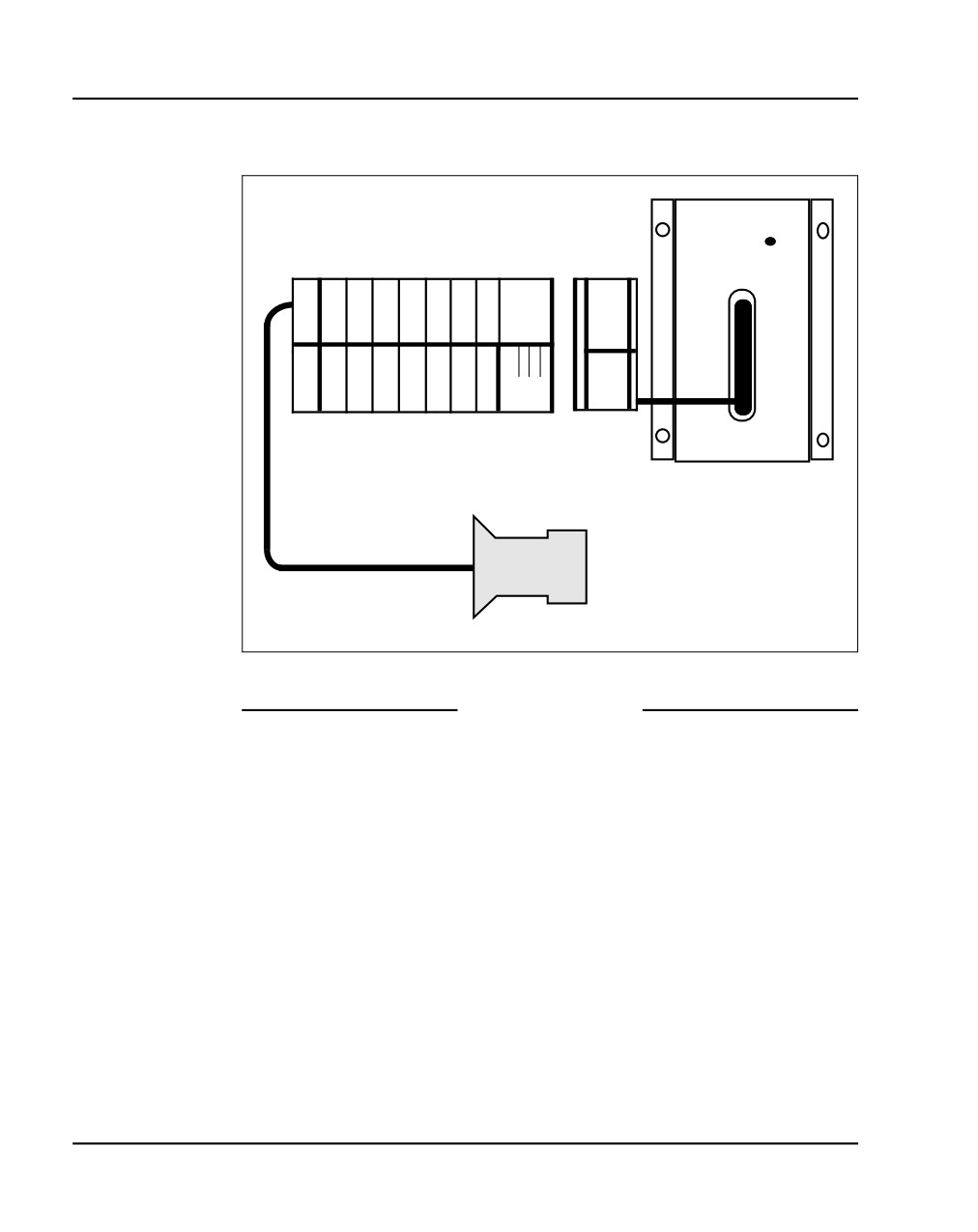
Connect the PFTU power and control connections to the AUX connector
on the Media Gateway. See Figure 179 on page 439 and Figure 180 on
page 440, Table 58 on page 440, and Figure 181 on page 442.
Figure 179
AUX cable connectors on media gateway
QUA6A
PFTU
XFER
A
W-
BL- O-
W-
G-
W-
U
BL
W
W
O
W
G
X
J1
P
T
R
T
R
T
R
TR
2
3
4
5
5
F
1
1
2
2
3
3
2
2
T
PFT1
U
V V
NTAK1104
553-CSE8343
Communication Server 1000E Installation and Commissioning
Page 440 of 466
Installing and cross-connecting a Power Fail Transfer Unit
Figure 180
AUX cable connector on Media Gateway
Table 58
Control and power connections on cable J1 (Part 1 of 2)
J1 Cable from QUA6
Function
Pair Number
Pair Color
Connects to
Cross-connects to
Control
1T
W-BL
(ALM)
Not used
1R
BL-W
BRTN
W-BL 1-dot connection on
AUX cable
2T
W-O
PFTS
W-O 1-dot connection on
AUX cable. Transfer begins
by applying ground to this
lead.
2R
O-W
BRTN
BL-W 1-dot connection on
AUX cable.
NN43041-310
Standard 01.11
October 2008

Installing and cross-connecting a Power Fail Transfer Unit
Page 441 of 466
Table 58
Control and power connections on cable J1 (Part 2 of 2)
J1 Cable from QUA6
Function
Pair Number
Pair Color
Connects to
Cross-connects to
3T
W-G
(TC)
Console transfer switch. See
console connections.
Transfer begins by applying
ground to this lead.
3R
G-W
Not used
4T
W-BR
Not used
4R
BR-W
Not used
PFTU
25T
S-V
-48 V
O-W 1-dot connection on
power
25R
V-S
-48 V
AUX cable. Maximum
250 mA draw on O-W lead.
Communication Server 1000E Installation and Commissioning
Page 442 of 466
Installing and cross-connecting a Power Fail Transfer Unit
Figure 181
Power fail transfer
QUA6A
PFTU
XFER
A
W-
BL- O-
W-
G-
W-
U
BL
W
W
O
W
G
X
J1
P
T
R
T
R
T
R
TR
2
3
4
5
5
F
1
1
2
2
3
3
2
2
T
PFT1
U
V V
NTAK1104
553-CSE8343
End of Procedure
NN43041-310
Standard 01.11
October 2008
Installing and cross-connecting a Power Fail Transfer Unit
Page 443 of 466
Installing and connecting a third-party PFTU
Follow the equipment manufacturer’s instructions for installing the PFTU.
Use the information in Table 59 to connect a third-party PFTU.
Table 59
PFTU control lead signals
Lead State
NTAK1104 AUX
When PFTU is in
When PFTU is in
cable lead
non-transferred state
transferred state
BRTN
GROUND
GROUND
BRTN
GROUND
GROUND
-48V AUX
-48V DC (250 mA max.)
-48V DC (250 mA max.)
PFTS
OPEN
GROUND
Note 1: Refer to Figure 180 on page 440 to see where the Auxiliary
cable connects to the CS 1000E system.
Note 2: If power is removed from the QUA6, a transfer of the PFTU can
occur.
Communication Server 1000E Installation and Commissioning
Page 444 of 466
Installing and cross-connecting a Power Fail Transfer Unit
Connecting an analog (500/2500-type) telephone to a PFTU
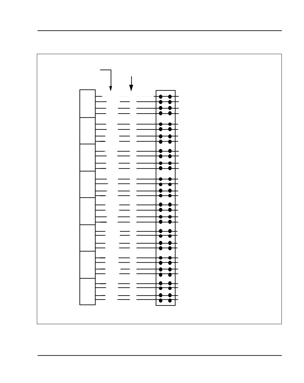
Ensure that the cable from the appropriate Line card slot has been connected
to the telephone. Refer to “Installing the Main Distribution Frame” on
page 349.
Follow Procedure 107 to connect an analog telephone to a PFTU. Refer to the
equipment layout plan to determine where to locate the PFTU.
DANGER
Always use caution when installing or modifying
telephone lines. Do not install telephone wiring during a
lightning storm. Do not install telephone jacks in wet
locations unless the jacks are designed for wet locations.
Never touch un-insulated telephone wiring unless the
line is disconnected at the network interface.
NN43041-310
Standard 01.11
October 2008
Installing and cross-connecting a Power Fail Transfer Unit
Page 445 of 466
Figure 182
Analog Line card cable distribution
Lead
Cable pairs
designation
Line
Cross connect
Pack
terminal
Unit
W-BL
T
To 500/2500-type
0
BL-W
R
telephone
Unit
W-O
T
To 500/2500-type
1
O-W
R
telephone
Unit
W-G
T
To 500/2500-type
2
G-W
R
telephone
Unit
W-BR
T
To 500/2500-type
3
BR-W
R
telephone
Unit
W-S
T
To 500/2500-type
4
S-W
R
telephone
Unit
R-BL
T
To 500/2500-type
5
BL-R
telephone
R
Unit
6
R-O
T
To 500/2500-type
O-R
R
telephone
Unit
R-G
T
To 500/2500-type
7
telephone
G-R
R
Unit
R-BR
T
To 500/2500-type
8
BR-R
R
telephone
Unit
R-S
T
To 500/2500-type
9
S-R
R
telephone
Unit
BK-BL
T
To 500/2500-type
10
BL-BK
R
telephone
Unit
BK-O
T
To 500/2500-type
11
O-BK
R
telephone
Unit
BK-G
T
To 500/2500-type
12
G-BK
R
telephone
Unit
BK-BR
T
To 500/2500-type
13
BR-BK
R
telephone
Unit
BK-S
T
To 500/2500-type
14
S-BK
R
telephone
Unit
Y-BL
T
To 500/2500-type
15
BL-Y
R
telephone
553-8349.EPS
Communication Server 1000E Installation and Commissioning

Page 446 of 466
Installing and cross-connecting a Power Fail Transfer Unit
Procedure 107
Connecting an analog (500/2500-type) telephone to a PFTU
1
Locate the telephone terminations on the cross-connect terminal.
2
Connect one end of the cross-connect wire to the leads of the telephone.
3
Locate the PFTU connections (unit PFTU 1 through PFTU 5) assigned to
this telephone at the cross-connect terminal. See Table 60 on page 446.
4
Connect the other end of the cross-connect wire to the pair assigned to
the telephone on the PFTU.
5
Connect a second cross-connect wire to the pair assigned to the Line card
on the PFTU.
6
Locate the Line card terminations on the cross-connect terminal.
7
Connect the other end of the cross-connect wire to the assigned TN
terminal block.
Table 60
Power Fail Transfer Unit connections (Part 1 of 3)
QUA6 J1 Cable
Function
Pair
Color
Connects to:
5T
W-S
Telephone
5R
S-W
6T
R-BL
Telephone Line card
6R
BL-R
PFT 1
7T
R-O
Central Office Trunk
7R
O-R
8T
R-G
Trunk Line card
8R
G-R
NN43041-310
Standard 01.11
October 2008

Installing and cross-connecting a Power Fail Transfer Unit
Page 447 of 466
Table 60
Power Fail Transfer Unit connections (Part 2
of 3)
QUA6 J1 Cable
Function
Pair
Color
Connects to:
9T
R-BR
Telephone
9R
BR-R
10T
R-S
Telephone Line card
10R
S-R
PFT 2
11T
BK-BL
Central Office Trunk
11R
BL-BK
12T
BK-O
Trunk Line card
12R
O-BK
13T
BK-G
Telephone
13R
G-BK
14T
BK-BR
Telephone Line card
14R
BR-BK
PFT 3
15T
BK-S
Central Office Trunk
15R
S-BK
16T
Y-BL
Trunk Line card
16R
BL-Y
17T
Y-O
Telephone
17R
O-Y
18T
Y-G
Telephone Line card
PFT 4
18R
G-Y
19T
Y-BR
Central Office Trunk
19R
BR-Y
20T
Y-S
Trunk Line card
20R
S-Y
Communication Server 1000E Installation and Commissioning

Page 448 of 466
Installing and cross-connecting a Power Fail Transfer Unit
Table 60
Power Fail Transfer Unit connections (Part 3 of 3)
QUA6 J1 Cable
Function
Pair
Color
Connects to:
21T
V-BL
Telephone
21R
BL-V
22T
V-O
Telephone Line card
22R
O-V
PFT 5
23T
V-G
Central Office Trunk
23R
G-V
24T
V-BR
Trunk Line card
24R
BR-V
End of Procedure
Connecting a trunk to a PFTU
Follow Procedure 108 to connect a Trunk to a PFTU.
Procedure 108
Connecting a Trunk to a PFTU
1
Locate the PFTU terminal blocks at the cross-connect terminal.
2
Cross-connect the first pair of the assigned PFTU to the telephone.
See Table 61 on page 449 for PFTU connections.
3
Cross-connect the second pair of the PFTU to the TN assigned to the
telephone.
4
Cross-connect the third pair of the PFTU to the Central Office trunk.
5
Cross-connect the third pair of the PFTU to the TN assigned to the trunk.
NN43041-310
Standard 01.11
October 2008

Installing and cross-connecting a Power Fail Transfer Unit
Page 449 of 466
6
Repeat for each trunk assigned to the PFTU.
Table 61
Power Fail Transfer Unit connections (Part 1 of 2)
QUA6 J1 cable
Function
Pair
Color
Connects to:
Connects to:
5T
W-S
Telephone
—
5R
S-W
P
F
6T
R-BL
Telephone Line card
TN assigned to the telephone
6R
BL-R
T
7T
R-O
Central office trunk
—
7R
O-R
1
8T
R-G
Trunk Line card
TN assigned to the Trunk
8R
G-R
9T
R-BR
Telephone
—
9R
BR-R
P
F
10T
R-S
Telephone Line card
TN assigned to the telephone
10R
S-R
T
11T
BK-BL
Central office trunk
—
11R
BL-BK
2
12T
BK-O
Trunk Line card
TN assigned to the Trunk
12R
O-BK
13T
BK-G
Telephone
—
13R
G-BK
P
14T
BK-BR
Telephone Line card
TN assigned to the telephone
F
14R
BR-BK
T
15T
BK-S
Central office trunk
—
15R
S-BK
3
16T
Y-BL
Trunk Line card
TN assigned to the Trunk
16R
BL-Y
Communication Server 1000E Installation and Commissioning

Page 450 of 466
Installing and cross-connecting a Power Fail Transfer Unit
Table 61
Power Fail Transfer Unit connections (Part 2 of 2)
QUA6 J1 cable
Function
Pair
Color
Connects to:
Connects to:
17T
Y-O
Telephone
—
17R
O-Y
P
F
18T
Y-G
Telephone Line card
TN assigned to the telephone
18R
G-Y
T
19T
Y-BR
Central office trunk
—
19R
BR-Y
4
20T
Y-S
Trunk Line card
TN assigned to the Trunk
20R
S-Y
21T
V-BL
Telephone
—
21R
BL-V
P
F
22T
V-O
Telephone Line card
TN assigned to the telephone
22R
O-V
T
23T
V-G
Central office trunk
—
23R
G-V
5
24T
V-BR
Trunk Line card
TN assigned to the Trunk
24R
BR-V
End of Procedure
NN43041-310
Standard 01.11
October 2008
456
Page 451 of 466
Installing and cross-connecting
an external alarm from a PFTU
Contents
This section contains information on the following topics:
Introduction
451
Installing an alarm using an alarm port assigned in LD 15
452
Installing an alarm through QUA6 PFTU connections
453
Introduction
This chapter describes the procedures for connecting an external alarm to the
CS 1000E system.
This chapter contains the following procedure: Procedure 109: "Installing an
alarm using an alarm port assigned in LD 15" on page 452
The following are the two methods of connecting an external alarm to the
CS 1000E system:
•
through an alarm port assigned in software
•
through contacts in a QUA6 Power Failure Transfer Unit (PFTU)
Communication Server 1000E Installation and Commissioning
Page 452 of 466
Installing and cross-connecting an external alarm from a PFTU
Installing an alarm using an alarm port assigned in LD 15
The system can be equipped with an alarm port that is assigned in software.
Connect an analog line to an analog (500/250-type) telephone or another
similar type of ringing or alerting device.
Follow Procedure 109 to install an alarm using an alarm port assigned in
LD 15.
Procedure 109
Installing an alarm using an alarm port assigned in LD 15
1
Install an analog (500/2500-type) line as described in “Installing and
configuring Nortel IP Phones” on page 391.
2
Connect an analog (500/2500-type) telephone, or another similar alerting
device used as an alarm, to the line.
3
Use LD 15 to assign an alarm port, (see Table 62).
Note: If the DN assigned to the alarm is accidentally called, the alarm
activates. To avoid false alarms, make sure the DN is not already
assigned.
Table 62
LD 15 - Assign an alarm port.
Prompt
Response
Comment
REQ
CHG
Change existing data
TYPE
CDB
Customer Data Block
CUST
xx
Customer Number as defined in LD 15
ALDN
x...x
Alarm Directory Number
End of Procedure
NN43041-310
Standard 01.11
October 2008
Installing and cross-connecting an external alarm from a PFTU
Page 453 of 466
Installing an alarm through QUA6 PFTU connections
A QUA6 PFTU can be used to connect an external alarm through normally
open or normally closed contacts of one of its units. The contacts operate
under the same conditions as the PFTU and can support the capacities listed
in Table 63.
Table 63
The AC capacities
Maximum
AC capacities
Switching power
50.0 V A
Switching voltage
125.0 V rms
Switching current
0.5 A
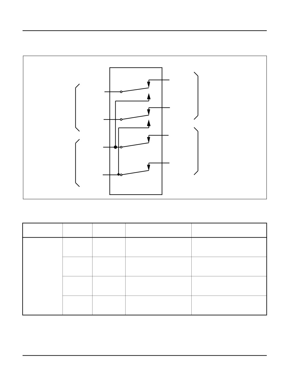
Figure 183 on page 454 is an example of the contacts on one unit (PFT1) of
the PFTU. The figure also shows the contacts in normal operating mode, not
in failure mode. Table 64 on page 454 provides the connections for all units
on the PFTU.
Communication Server 1000E Installation and Commissioning
Page 454 of 466
Installing and cross-connecting an external alarm from a PFTU
Figure 183
Contacts in PFTU
PFT 1 on PFTU
8T (R-G)
Normally
7T (R-O)
connected
Normally
connected
to a
trunk line card
to a
8R (G-R)
CO trunk
7R (O-R)
6T (R-BL)
Normally
5T (W-S)
connected
Normally
to a
connected
telephone line card
to a
6R (BL-R)
telephone
5R (S-W)
Table 64
PFTU connections (Part 1 of 3)
Unit
Pair
Color
Normal mode
Failure mode
5T
W-S
Makes with 6T and 6R
Opens 6T and 6R
5R
S-W
Makes with 7T and 7R
P
6T
R-BL
Makes with 5T and 5R
Open
F
6R
BL-R
T
7T
R-O
Makes with 8T and 8R
Opens 8T and 8R
7R
O-R
Makes with 5T and 5R
1
8T
R-G
Makes with 7T and 7R
Open
8R
G-R
NN43041-310
Standard 01.11
October 2008

Installing and cross-connecting an external alarm from a PFTU
Page 455 of 466
Table 64
PFTU connections (Part
2 of 3)
Unit
Pair
Color
Normal mode
Failure mode
9T
R-BR
Makes with 10T and
Opens 10T and 10R
9R
BR-R
10R
Makes with 11T and 11R
P
10T
R-S
Makes with 9T and 9R
Open
F
10R
S-R
T
11T
BK-BL
Makes with 12T and
Opens 12T and 12R
11R
BL-BK
12R
Makes with 9T and 9R
2
12T
BK-O
Makes with 11T and
Open
12R
O-BK
11R
13T
BK-G
Makes with 14T and
Opens 14T and 14R
13R
G-BK
14R
Makes with 15T and 15R
P
14T
BK-BR
Makes with 13T and
Open
F
14R
BR-BK
13R
T
15T
BK-S
Makes with 16T and
Opens 16T and 16R
15R
S-BK
16R
Makes with 13T and 13R
3
16T
Y-BL
Makes with 15T and
Open
16R
BL-Y
15R
17T
Y-O
Makes with 18T and
Opens 18T and 18R
17R
O-Y
18R
Makes with 19T and 19R
P
18T
Y-G
Makes with 17T and
Open
F
18R
G-Y
17R
T
19T
Y-BR
Makes with 20T and
Opens 20T and 20R
19R
BR-Y
20R
Makes with 17T and 17R
4
20T
Y-S
Makes with 19T and
Open
20R
S-Y
19R
Communication Server 1000E Installation and Commissioning

Page 456 of 466
Installing and cross-connecting an external alarm from a PFTU
Table 64
PFTU connections (Part 3 of 3)
Unit
Pair
Color
Normal mode
Failure mode
21T
V-BL
Makes with 22T and
Opens 22T and 22R
21R
BL-V
22R
Makes with 23T and 23R
P
22T
V-O
Makes with 21T and
Open
F
22R
O-V
21R
T
23T
V-G
Makes with 24T and
Opens 24T and 24R
23R
G-V
24R
Makes with 21T and 21R
5
24T
V-BR
Makes with 23T and
Open
24R
BR-V
23R
NN43041-310
Standard 01.11
October 2008
462
Page 457 of 466
Basic system telephony configuration
Contents
This section contains information on the following topics:
Introduction
457
Basic system configuration
457
TN assignment
462
TN assignment
462
Introduction
This chapter shows overlay (LD) sequences required to configure the system
with basic telephony features. Your Planning and Engineering group provides
the details needed to configure basic telephony.
Note: The Command Line Interface (CLI) must be used for some
configuration (for example, LD 10 and LD 11) before Element Manager
can be used to further configure basic telephony.
This chapter contains Procedure 110: "Configuring the basic system" on
page 458.
Basic system configuration
Programming the CS 1000E system requires loading different overlay
programs and using each one to enter a specific type of information.
Communication Server 1000E Installation and Commissioning
Page 458 of 466
Basic system telephony configuration
See Software Input/Output: Administration (NN43001-611) for information
about overlays.
Flow charts
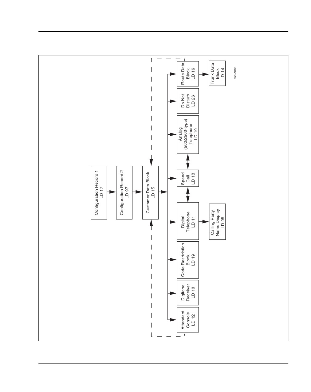
Figure 184 on page 459 shows the programming overlay (LD) sequence for a
new system. The Data-entry-sequence flowchart does not show all possible
administration overlays.
In some cases, you must move back and forth between overlays to complete
the programming. For example, you must program the Customer Data Block
(CDB) before you program the attendant console. However, there are
console-related prompts in the CDB that cannot be programmed until you
have programmed an attendant console. Skip the console-related prompts,
complete the CDB programming, then return to the CDB after the console is
programmed. Finish the CDB console-related prompts. A similar situation
exists with the Speed Call lists and the Telephones. You must activate the
Speed Call list(s) before you can assign the list(s) to a telephone.
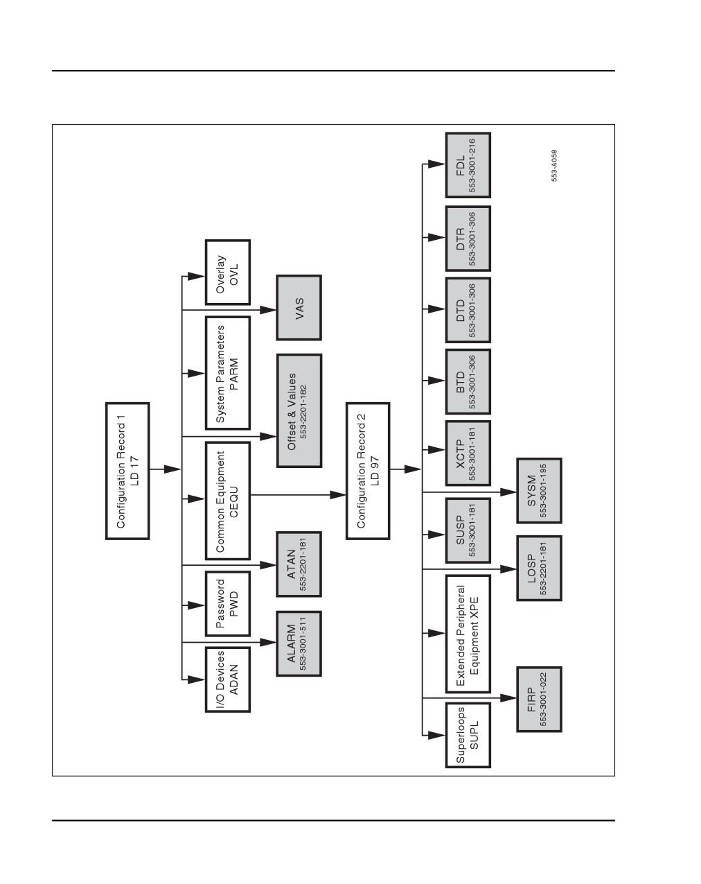
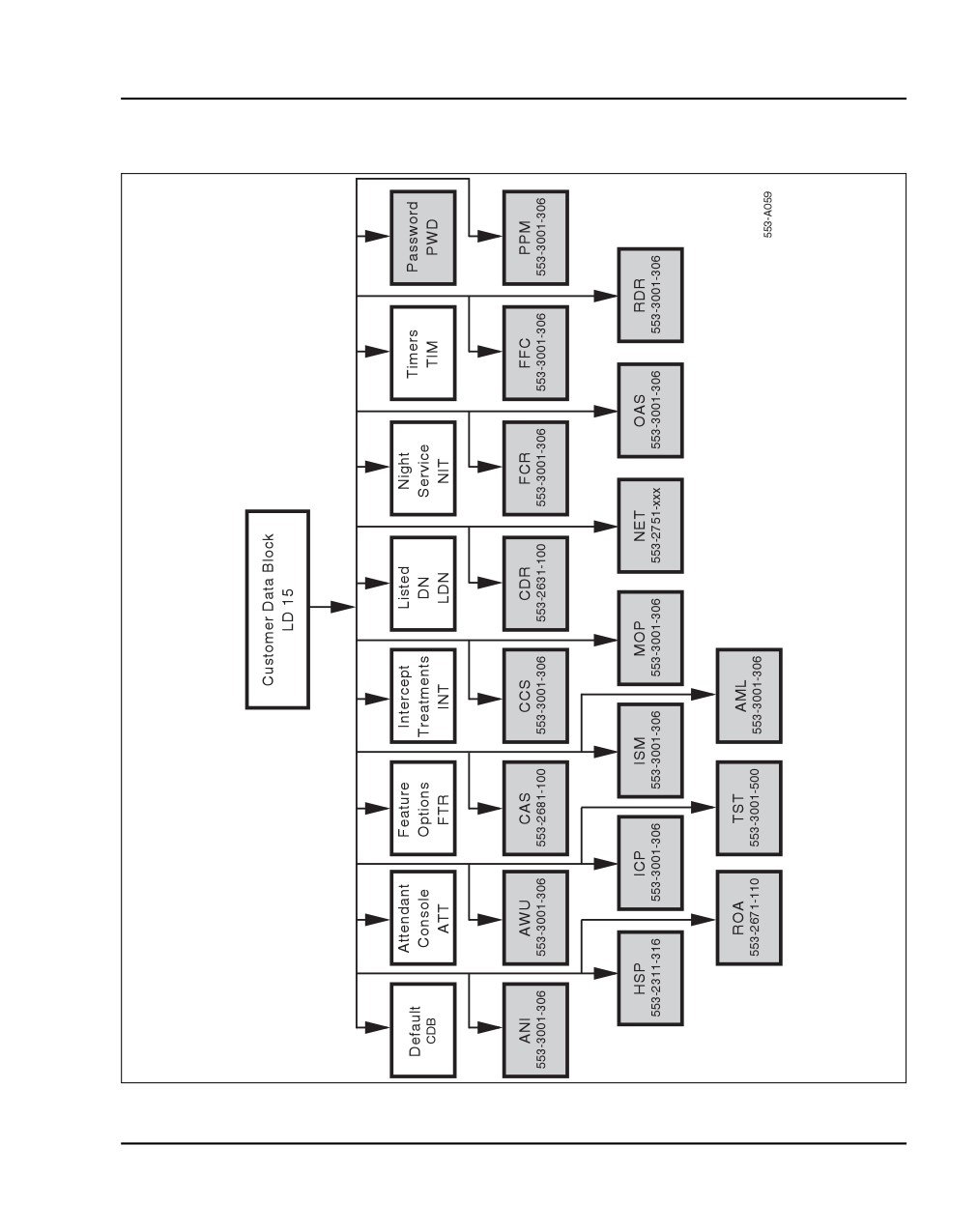
Figure 185 on page 460, and Figure 186 on page 461 show overlay titles and
gate openers for each feature group. A gate opener enables users to program
a related group of features without stepping through all prompts of an overlay.
NTP references are shown in the flowchart shaded boxes for those features
and options beyond the scope of this guide.
Procedure 110
Configuring the basic system
Use the overlays to configure basic system features offered by the CS 1000E.
1
Complete the configuration using the overlays in the order shown in
Figure 184 on page 459, Figure 185 on page 460, and Figure 186 on
page 461.
NN43041-310
Standard 01.11
October 2008
Basic system telephony configuration Page 459 of 466
Figure 184
Data-entry-sequence for new systems
Communication Server 1000E Installation and Commissioning
Page 460 of 466
Basic system telephony configuration
Figure 185
Configuration Record
NN43041-310
Standard 01.11
October 2008
Basic system telephony configuration Page 461 of 466
Figure 186
Customer Data Block
Communication Server 1000E Installation and Commissioning

Page 462 of 466
Basic system telephony configuration
TN assignment
Table 65 shows the TN assignments for the MG 1000E.
Table 65
TN assignments for MG 1000E
MG 1000E
MG 1000E Expander
Slots
1
2
3
4
7
8
9
10
TN
l s c
l s c
l s c
l s c
l s c
l s c
l s c
l s c
MG 1000E
1
000 0 01
000 0 02
000 0 03
000 0 04
000 0 07
000 0 08
000 0 09
000 0 10
2
000 1 01
000 1 02
000 1 03
000 1 04
000 1 07
000 1 08
000 1 09
000 1 10
3
004 0 01
004 0 02
004 0 03
004 0 04
004 0 07
004 0 08
004 0 09
004 0 10
4
004 1 01
004 1 02
004 1 03
004 1 04
004 1 07
004 1 08
004 1 09
004 1 10
5
008 0 01
008 0 02
008 0 03
008 0 04
008 0 07
008 0 08
008 0 09
008 0 10
6
008 1 01
008 1 02
008 1 03
008 1 04
008 1 07
008 1 08
008 1 09
008 1 10
7
012 0 01
012 0 02
012 0 03
012 0 04
012 0 07
012 0 08
012 0 09
012 0 10
8
012 1 01
012 1 02
012 1 03
012 1 04
012 1 07
012 1 08
012 1 09
012 1 10
9
016 0 01
016 0 02
016 0 03
016 0 04
016 0 07
016 0 08
016 0 09
016 0 10
10
016 1 01
016 1 02
016 1 03
016 1 04
016 1 07
016 1 08
016 1 09
016 1 10
11
020 0 01
020 0 02
020 0 03
020 0 04
020 0 07
020 0 08
020 0 09
020 0 10
12
020 1 01
020 1 02
020 1 03
020 1 04
020 1 07
020 1 08
020 1 09
020 1 10
13
024 0 01
024 0 02
024 0 03
024 0 04
024 0 07
024 0 08
024 0 09
024 0 10
14
024 1 01
024 1 02
024 1 03
024 1 04
024 1 07
024 1 08
024 1 09
024 1 10
127
252 0 01
252 0 02
252 0 03
252 0 04
252 0 07
252 0 08
252 0 09
252 0 10
128
252 1 01
252 1 02
252 1 03
252 1 04
252 1 07
252 1 08
252 1 09
252 1 10
Note: The bottom most card slot in the Media Gateway is reserved for the SSC card.
NN43041-310
Standard 01.11
October 2008
466
Page 463 of 466
Configuring IP Peer Networking and
managing the Gatekeeper database
Contents
This section contains information on the following topics:
Introduction
463
Implementation summary
463
Introduction
This chapter provides an outline for configuring IP Peer Networking and
managing the Gatekeeper database.
Use the IP Peer Networking: Installation and Commissioning
(NN43001-313) NTP to configure IP Peer Networking and for instructions
about managing the Gatekeeper database.
Implementation summary
Note: This section is intended as a summary of how to implement
IP Peer Networking and how to manage the Gatekeeper database. Many
of these steps can be performed out of sequence.
Communication Server 1000E Installation and Commissioning
Page 464 of 466
Configuring IP Peer Networking and managing the Gatekeeper database
You must configure the following data when setting up a CS 1000E
IP network:
1
Configure the Virtual Trunk routes using Element Manager or the
Command Line Interface (LD 16). Configure the Route Data Blocks and
associate the Virtual Trunk routes with the IP network by configuring the
following parameters:
a route information
b network management information
(for example, Access Restrictions)
c bandwidth zone
d Signaling Server host name for the route
e protocol identifier
f
associated Node ID
2
Configure the Virtual Trunks using Element Manager or the Command
Line Interface (LD 14).
3
Configure the network routing within the CS 1000E.
a Use existing tools to configure networking features, such as routing
calls based on digits dialed.
b Configure dialing plan information for calls that must be routed to
circuit-switched trunks (for example, PSTN interfaces). You can
route these calls using a feature such as Network Alternate Route
Selection (NARS). Configure Virtual Trunk routes in NARS the
same way as traditional trunks.
4
Configure the Primary, Alternate, and Failsafe Gatekeepers at
installation and initial setup.
NN43041-310
Standard 01.11
October 2008
Configuring IP Peer Networking and managing the Gatekeeper database Page 465 of 466
5
Configure the Gatekeeper database to provide a central database of
addresses that are required to route calls across the network, using the
Gatekeeper web pages in Element Manager.
a
Log in to the Gatekeeper web pages in Element Manager.
b
Verify that the Gatekeeper is the Primary Gatekeeper and is active.
c
Configure the System Wide Settings.
d
Create the CDP domains.
e
Add the RAS and non-RAS endpoints.
f
Add the endpoint prefixes.
g
Add the Numbering Plan entries for each endpoint, including the
Cost Factor for each entry.
h
Add the default routes.
i
Add the Gatekeeper zones (if required).
j
Test the Numbering Plans.
k
Perform database cutover.
l
Perform the following operations, as necessary:
i.
Take the Gatekeeper out-of-service.
ii.
Perform database cutover.
iii. Perform database rollback.
iv. View traffic reports.
m
Log out of the Gatekeeper web pages in Element Manager.
Communication Server 1000E Installation and Commissioning