Nortel Communication Server 1000. Installation And Commissioning Manual (2008) - page 2
116
Page 101 of 466
Installing and connecting CS 1000E
hardware
Contents
This section contains information on the following topics:
Introduction
101
Connecting CP PM Call Server 0 to CP PM Call Server 1
102
Installing the cards
104
Cabling the cards
107
Inserting a Shielded 50-pin to Serial/ELAN/TLAN
adapter onto a Media Card
112
Connecting a Media Card to the ELAN subnet
114
Connecting a Media Card to the TLAN subnet
115
Connecting a Media Gateway to a Media Gateway Expansion
115
Introduction
Several system connections are required to make the CS 1000E operational.
The CS 1000E must be connected to the MG 1000E through the ELAN
subnet. The Media Gateways are directly connected to the Media Gateway
Expander. The system’s components, such as the ISP1100 Signaling Server
and the Media Cards installed in the Media Gateway, require both ELAN
subnet and TLAN subnet connections.
This chapter contains the following procedures:
•
Procedure 9: "Connecting co-located CP PM Call Servers" on page 103
Communication Server 1000E Installation and Commissioning
Page 102 of 466
Installing and connecting CS 1000E hardware
•
Procedure 10: "Connecting Campus Redundant CP PM Call Servers"
on page 104
•
Procedure 11: "Installing a DSP Daughterboard" on page 105
•
Procedure 12: "Installing the MGC card" on page 105
•
Procedure 13: "Installing the CP PM card" on page 106
•
Procedure 14: "Inserting a Shielded 50-pin to Serial/ELAN/TLAN
adapter" on page 113
•
Procedure 15: "Connecting a Media Card to the ELAN subnet"
on page 114
•
Procedure 16: "Connecting a Media Card to the TLAN subnet"
on page 115
•
Procedure 17: "Connecting a Media Gateway to a Media Gateway
Expansion" on page 115.
Connecting CP PM Call Server 0 to CP PM Call Server 1
The CS 1000E redundant architecture allows for the separation of
Call Server 0 and Call Server 1. The two processors are connected by either
a direct 100BaseT crossover cable or a carefully engineered Layer 2/VLAN
infrastructure.
Campus Redundancy provides the ability to separate the CS 1000E CP PM
Call Servers in a campus environment for “campus mirroring”. This feature
enables two CP PM Call Servers, one active and one redundant, to be
connected through an Ethernet network interface. Campus Redundancy can
operate using any vendor’s Layer 2 switching products, in addition to the
BayStack 470. The distance depends upon network parameter limitations
specified in Communication Server 1000: System Redundancy
(NN43001-507).
To separate the redundant CP PM Call Servers, the ELAN subnet and the
subnet of the High Speed Pipe (HSP) can be extended between the two
processors with an Ethernet switch, using Layer 2 protocol.
If the two CP PM Call Servers are collocated, they can be connected using a
standard CAT5e or CAT6 crossover cable, limited to 100 meters in length.
NN43041-310
Standard 01.11
October 2008
Installing and connecting CS 1000E hardware Page 103 of 466
For detailed information on Campus Redundancy, refer to Communication
Server 1000: System Redundancy (NN43001-507).
The Layer 2 switch allows the ELAN subnet and the subnet of the High Speed
Pipe (HSP) to be extended between the two processors. The
BayStack 470-24T provides full duplex wire-speed 100BaseT with no
significant packet loss (less than 0.001%) and delays of less than 100 usec.
The method used to connect CP PM Call Server 0 to CP PM Call Server 1
depends on the proximity of the units. If the units are co-located, follow
Procedure 9 to connect the CP PM Call Servers. If the units are configured for
Campus Redundancy, follow Procedure 10 to connect the CP PM Call
Servers.
Connecting co-located CP PM Call Servers
Follow Procedure 9 to connect co-located CP PM Call Servers.
Procedure 9
Connecting co-located CP PM Call Servers
1
Plug one end of the CAT5E RJ-45 crossover cable (NTRC17) into the
LAN 2 connector on the front of Call Server 0.
2
Plug the other end of the CAT5E RJ-45 NTRC17 crossover cable into the
LAN 2 connector on the front of Call Server 1.
End of Procedure
Connecting Campus Redundant CP PM Call Servers
The MultiLink Trunking (MLT) feature of the BayStack 470-24T enables the
two uplink fiber ports to be grouped but is not solely necessary for the two
uplink fiber ports to be linked. Grouping the uplink fiber ports increases
aggregate throughput up to 2 Gbps between sides with active redundant links.
The port-based VLANs used in the BayStack 470-24T switches operate in
accordance with the IEEE 802.1Q tagging rules. VLAN ports are grouped
into broadcast domains by assigning them to the same VLAN. Frames
received in one VLAN can be forwarded only within that VLAN. For more
Communication Server 1000E Installation and Commissioning
Page 104 of 466
Installing and connecting CS 1000E hardware
information, see Communication Server 1000: System Redundancy
(NN43001-507).
Procedure 10
Connecting Campus Redundant CP PM Call Servers
1
Connect the CAT5E RJ-45 LAN 2 port of Call Server 0 to a 100BaseT
ELAN network interface on the local Baystack 470-24T switch.
2
Connect the CAT5E RJ-45 LAN 2 port of Call Server 1 to a 100BaseT port
on the remote Baystack 470-24T switch.
3
Link the two Baystack 470-24T switches with two high-speed single-mode
fiber uplinks (1 Gbps per link), using the built-in GBIC ports for dedicated
uplink connectivity.
4
Assign three VLANs to the BayStack 470-24T ports.
•
VLAN 1 - Default
— All 104 ports belong to the four BayStack 470-24T ports.
•
VLAN 2 - HSP
— Two ports connect CP PM packs HSP ports in Call Server 0 and
Call Server 1.
— Four high-speed fiber uplinks (GBIC ports)
•
VLAN 3 - ELAN
— Includes 2 ELAN network interfaces on the CP PM Call Servers,
for example, for ELAN connections for ISP1100 Signaling
Servers, MG 1000Es, Call Pilot, Symposium, OTM, Element
Manager.
— Four high-speed fiber uplinks (GBIC ports)
End of Procedure
Installing the cards
Installing a DSP Daughterboard
The following procedure describes how to install a DSP Daughterboard on an
MGC card:
NN43041-310
Standard 01.11
October 2008
Installing and connecting CS 1000E hardware Page 105 of 466
Procedure 11
Installing a DSP Daughterboard
1
Place the MGC on a safe ESD surface.
2
Place the DSP DB in either DB position 1 (for DSP DB-96) or DB position
2 (for DSP DB-32), or both, depending on how the Daughterboards will be
configured from a TN perspective.
3
Ensure the DSP DB is securely attached to the MGC (using the four
supplied screws and standoffs).
Note: Note: Call Server dongles do not need to be retained for IPMGs.
End of Procedure
Installing the MGC card
Procedure 12
Installing the MGC card
IMPORTANT!
You must ensure that all dongles (for both MGC and CP PM cards) are
correctly identified.
You must destroy or return the SSC dongle to your local
Nortel Repairs/Returns center.
For the CP PM call server you must use the dongle provided with the
software kit.
To install the MGC card, perform the following steps:
1
Power down the Main Chassis.
2
Remove the SSC card.
3
Install the DSP Daughterboard on the MGC card as described in
Procedure 11 on page 105.
4
Insert the MGC into Slot 0 of the Chassis.
Communication Server 1000E Installation and Commissioning
Page 106 of 466
Installing and connecting CS 1000E hardware
5
The existing 3-port SDI cable (NTBK48AA) is reused. It connects to the
SDI port on the Chassis.
This chassis, the main chassis in the system, will now become known as
IPMG 00.
End of Procedure
Installing the CP PM card
The following procedure describes how to install the CP PM card in a
Chassis.
Note: Ensure that all DIP switches are set correctly. DIP switches
determine whether the CP PM boots from a hard drive or compact flash.
Procedure 13
Installing the CP PM card
1
Ensure that the security dongle (the one that comes as part of the
software kit) is inserted on the CP PM call processor.
2
Slide the CP PM call processor into Slot 1 (or higher) of the Chassis.
3
Lock the card into the faceplate latches.
4
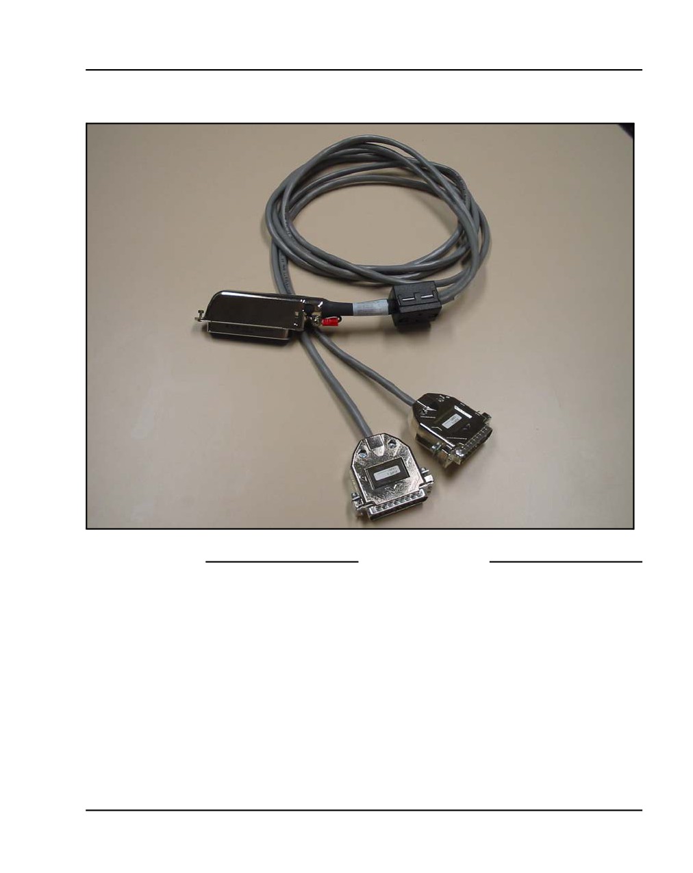
Attach the SDI cable. The 50-pin Amphinol connects to the back of the
CP PM call server.
NN43041-310
Standard 01.11
October 2008
Installing and connecting CS 1000E hardware Page 107 of 466
Figure 23
2-port SDI cable (NTAK19EC) cable
End of Procedure
Cabling the cards
The following sections describe the process required to cable the MGC and
CP PM cards.
Cabling the MGC
The existing 3-port SDI cable (NTBK48AA) is reused. It connects to the SDI
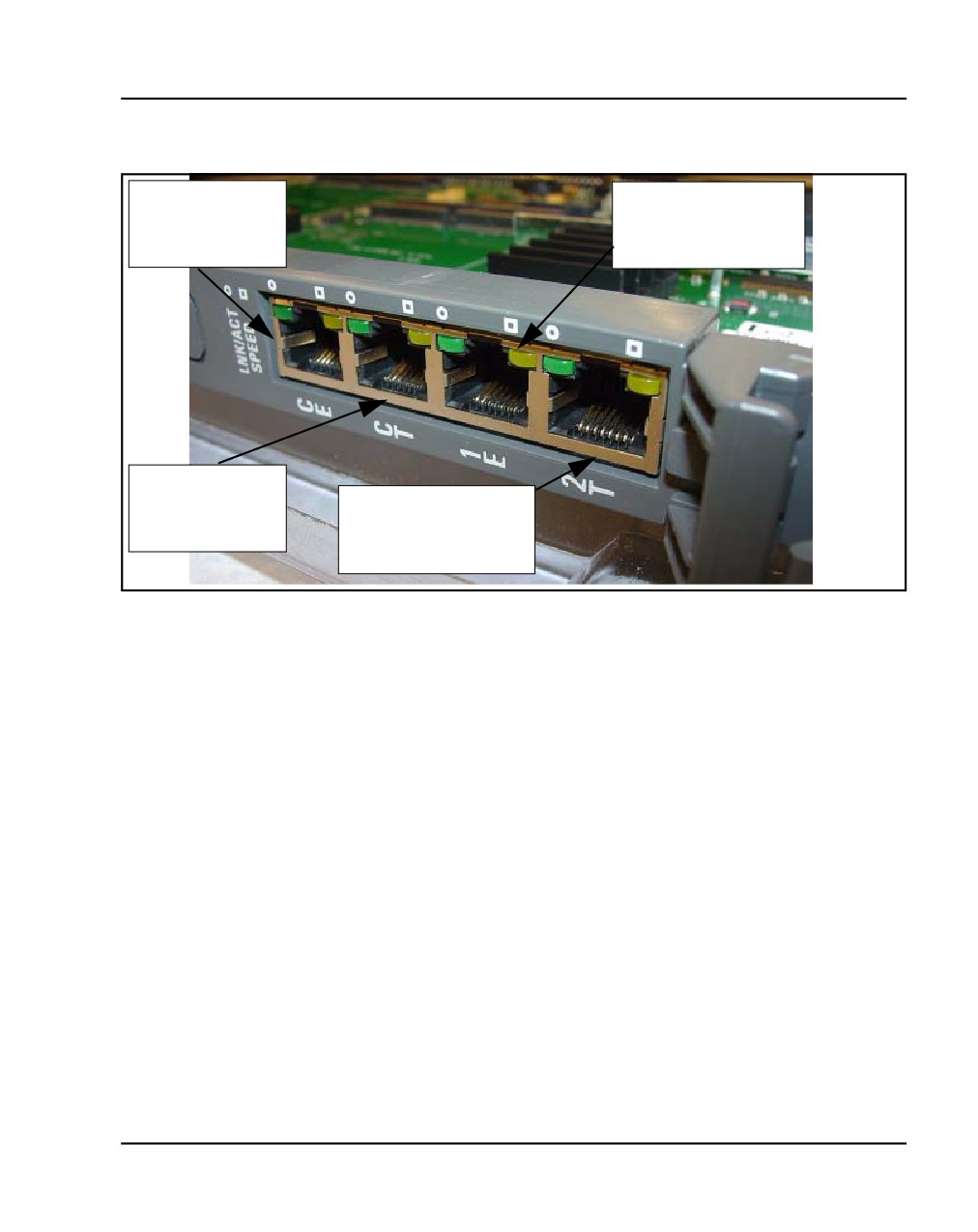
port on the Chassis. Figure 24 on page 109 shows front of MGC. The CE and
CT ports are reserved for the CP PM card only. The CE connects to the ELAN
Communication Server 1000E Installation and Commissioning
Page 108 of 466
Installing and connecting CS 1000E hardware
port of the call server, while the CT connects to the TLAN port of the call
server. The 1E and 2T ports must be attached to the layer 2 switch.
MGC Ethernet Capabilities
An MGC features six Ethernet interfaces set to auto-negotiate by default: four
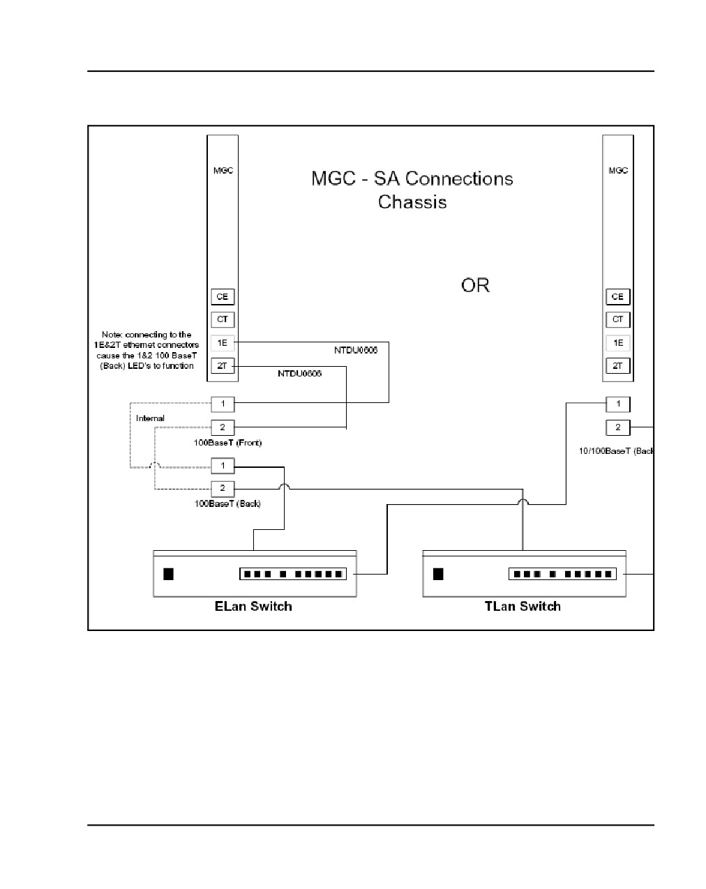
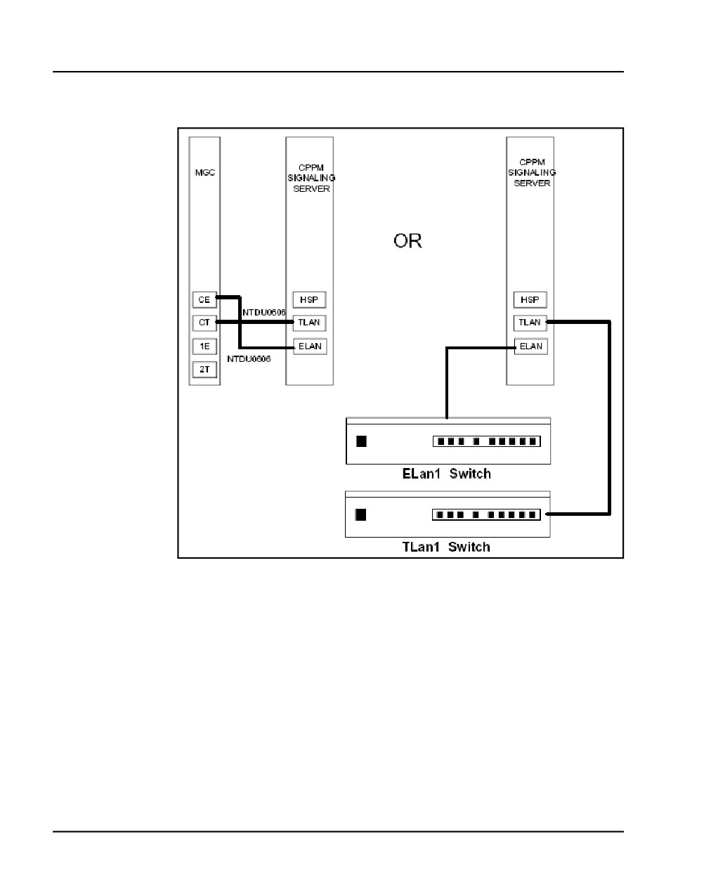
on the faceplate (see Figure 24 on page 109), and two on the back. Figure 25
on page 110, Figure 26 on page 111, and Figure 27 on page 112 illustrate the
various ethernet connections.
Connecting the CS 1000E Core CP PM Call Servers to an
MG 1000E
An MG 1000E performs functions under the direct control of the CS 1000E
Core CP PM Call Server. The MG 1000E detects stimulus events from its
interface cards and passes these events to the CS 1000E Core CP PM Call
Server, where the high-level call processing decisions are made.
The NTBK48AA 3-port SDI cable connects to the SDI port on the Cabinet.
Figure 24 on page 109 shows front of MGC with the "bulkhead" connectors
(1E and 2T) that connect to numbers 1 and 2 bulkhead. The CE and CT
connect to the ELAN port. The 100 Base T ports 1 and 2 connect to the
bulkhead, while ports 1 and 2 in the lower left connect to the backplane.
NN43041-310
Standard 01.11
October 2008
Installing and connecting CS 1000E hardware Page 109 of 466
Figure 24
MGC faceplate
CE: ELAN
1E: ELAN
Dedicated for
Dual homed with
CPPM-CS
Backplane E
CT: TLAN
Dedicated for
2T: TLAN
CPPM-CS
Dual homed with
Backplane T
Note: The MG1000E can be connected directly to the CS1000E ELAN
subnet, or it can be connected to the ELAN subnet through a Layer 2
switch.
Cabling the CP PM call server
In a typical configuration, the com (SDI) port of the CP PM call server is
routed through the backplane of the shelf to the 50-pin Amphinol connector
on the back of the shelf. A special cable is shipped with the CP PM call server
that adapts the 50-pin Amphinol to a 25-pin DB connector (NTAK19EC).
Port 0 is used for maintenance access, and Port 1 is for an external modem
connection.
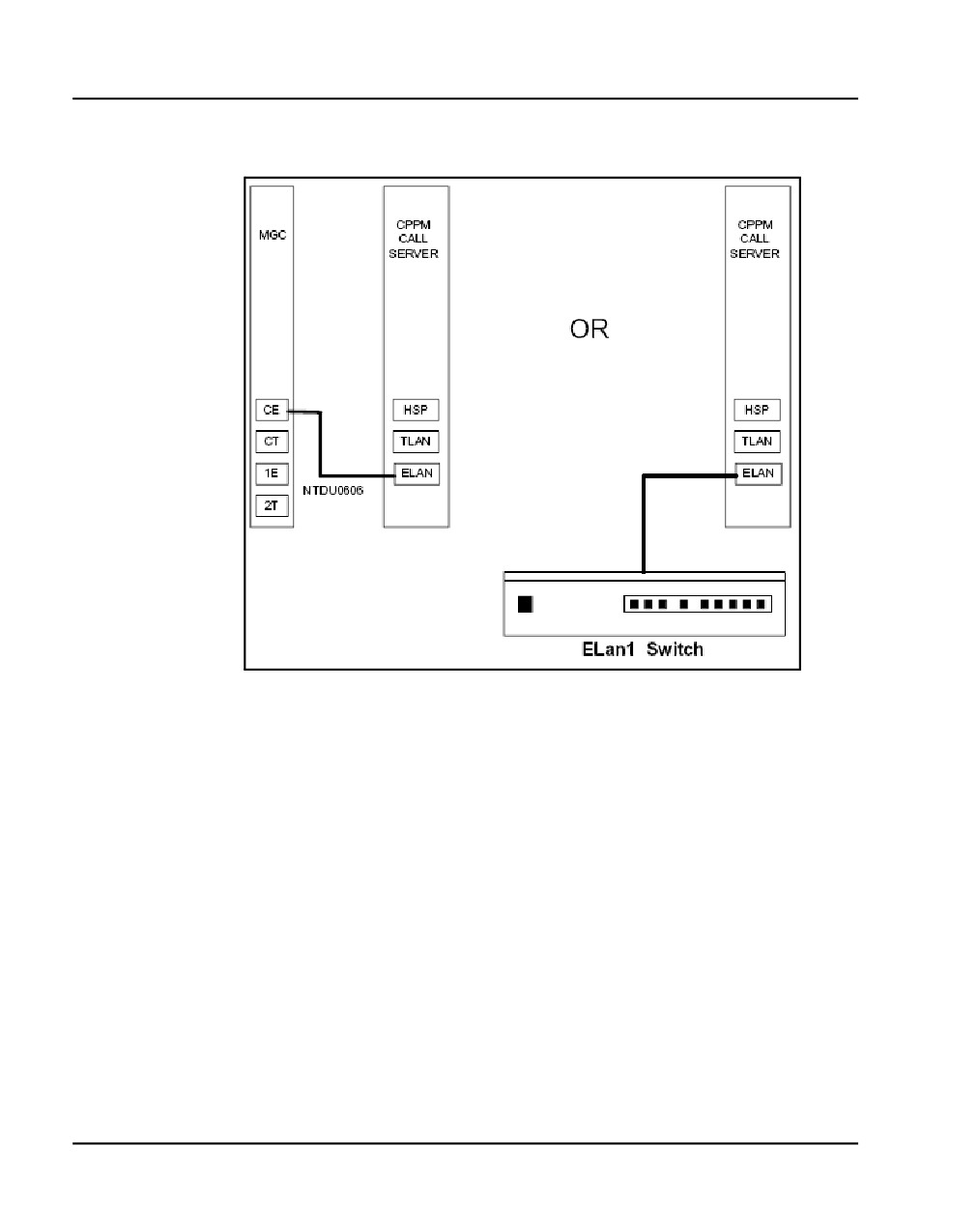
Connect the ELAN of CP PM to the CE port of the MGC card or to the VLAN
of the external layer 2 switch that is dedicated to ELAN traffic for the system.
The following diagrams illustrate the different ways to connect the CP PM
Call Server, MGC, and CP PM Signaling Server cards.
Communication Server 1000E Installation and Commissioning
Page 110 of 466
Installing and connecting CS 1000E hardware
Figure 25
Elan connection (CP PM Call Server)
NN43041-310
Standard 01.11
October 2008
Installing and connecting CS 1000E hardware Page 111 of 466
Figure 26
Elan connections (MGC)
Communication Server 1000E Installation and Commissioning
Page 112 of 466
Installing and connecting CS 1000E hardware
Figure 27
Ethernet connections for CP PM Signaling Server
Note: Refer to Figure 26 on page 111 for a visual representation of
MGC card cabling (from port 1E and 2T) out to the layer 2 switch.
Inserting a Shielded 50-pin to Serial/ELAN/TLAN
adapter onto a Media Card
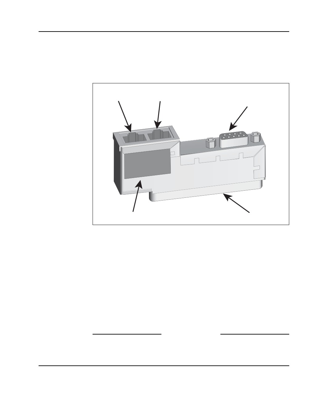
The Shielded 50-pin to Serial/ELAN/TLAN adapter shown in Figure 28
provides access to the TLAN and ELAN Ethernet Ports. The adapter breaks
out the signals from the I/O connector to the following:
•
ELAN (management) network interface
NN43041-310
Standard 01.11
October 2008
Installing and connecting CS 1000E hardware Page 113 of 466
•
TLAN (telephony) network interface
•
one RS-232 (local console) port
Figure 28
Shielded 50-pin to Serial/ELAN/TLAN adapter
TLAN RJ-45
ELAN RJ-45
RS-232 Connector
LAN socket
LAN socket
Voice Gateway Media Card
maintenance port
Identification Label
50-pin connector
Procedure 14
Inserting a Shielded 50-pin to Serial/ELAN/TLAN adapter
1
Open the Media Card package NTDU41CA.
2
Remove the Shielded 50-pin to Serial/ELAN/TLAN adapter.
3
Save the other items from the package for use in “Installing a
CompactFlash” on page 328.
4
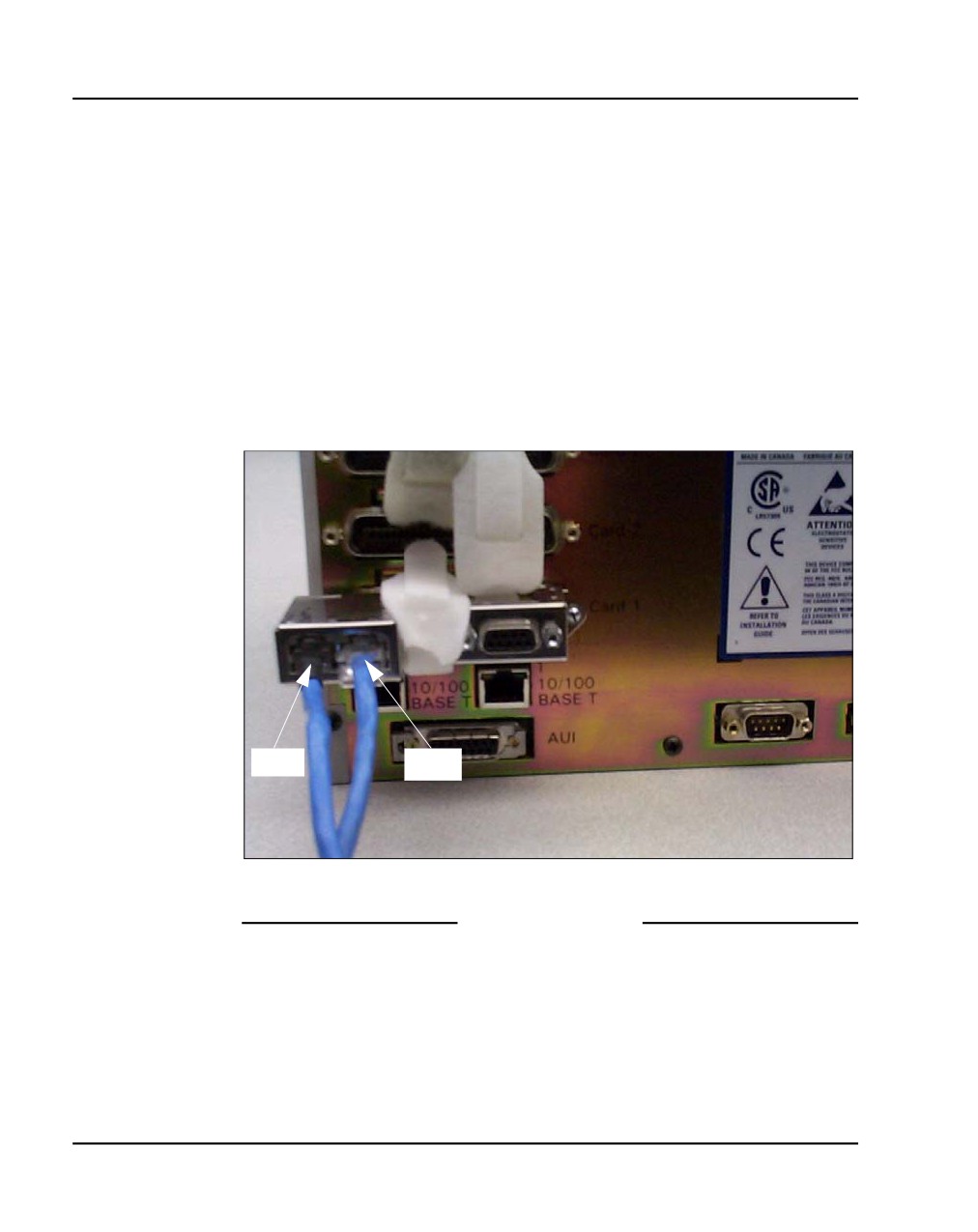
Insert the adapter, shown in Figure 28, into the connector Card 1, Card 2,
Card 3, or Card 4 that corresponds to the location of the Media Card.
For example, in Figure 29 on page 114, the Media Card is installed in card
slot 1. Therefore, the adaptor is installed in connector Card 1.
End of Procedure
Communication Server 1000E Installation and Commissioning
Page 114 of 466
Installing and connecting CS 1000E hardware
Connecting a Media Card to the ELAN subnet
Follow Procedure 15 to connect a Media Card to the ELAN.
Procedure 15
Connecting a Media Card to the ELAN subnet
1
Connect a standard CAT5 patch cable to the ELAN network interface on
the Adaptor (Figure 29 on page 114).
2
Connect the other end of the standard CAT5 patch cable to an RJ-45
ELAN network interface on the BayStack 470 switch
Figure 29
Shielded 50-pin to Serial/ELAN/TLAN adapter on the Media Gateway
TLAN
ELAN
End of Procedure
NN43041-310
Standard 01.11
October 2008
Installing and connecting CS 1000E hardware Page 115 of 466
Connecting a Media Card to the TLAN subnet
Follow Procedure 16 to connect a Media Card to the TLAN subnet.
Procedure 16
Connecting a Media Card to the TLAN subnet
1
Connect a standard CAT5 patch cable to the TLAN network interface on
the adaptor (see Figure 29 on page 114).
2
Connect the other end of the standard CAT5 patch cable to an RJ-45
TLAN network interface on the BayStack 470 switch.
End of Procedure
Connecting a Media Gateway to a Media Gateway
Expansion
Procedure 17 describes how to connect a Media Gateway Expander to the
Media Gateway. The Media Gateway Expander Cable Kit (NTDK89)
contains two NTDK95 cables used to connect the Media Gateway Expander
to the Media Gateway. One cable provides DS-30X connectivity while the
second cable provides CE-MUX connectivity to slot 10 only.
Procedure 17
Connecting a Media Gateway to a Media Gateway Expansion
1
Connect the non-labeled side of NTDK95 cable to the CE-MUX connector
at the back of the Media Gateway and labeled side of NTDK95(labeled as
Expansion Cabinet DS-30/CE-MUX Conn) to the CE-MUX connector at
the back of the Media Gateway Expander.
2
Tighten the screws on the connectors.
3
Connect the other NTDK95 cable (non-labeled side) to the DS-30X
connector at the back of the Media Gateway and labeled side of
NTDK95(labeled as Expansion Cabinet DS-30/CE-MUX Conn) to the
DS-30X connector at the back of the Media Gateway Expander.
4
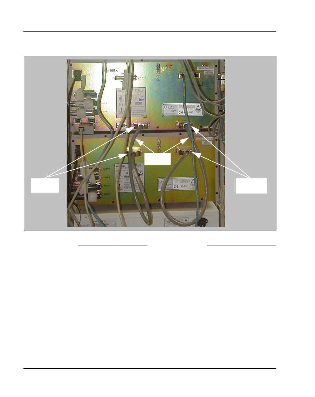
Tighten the screws on the connectors. Figure 30 on page 116 shows the
Media Gateway and Media Gateway Expander connected with the two
NTDK95 cables.
Communication Server 1000E Installation and Commissioning
Page 116 of 466
Installing and connecting CS 1000E hardware
Figure 30
Media Gateway and Media Gateway Expander connections
NTDK95
cables
DS-30X
CE-MUX
connector
connector
End of Procedure
NN43041-310
Standard 01.11
October 2008
150
Page 117 of 466
Installing software on the CS 1000E
Contents
This section contains information on the following topics:
Introduction
117
Installing the software
118
Configuring initial IP configuration data on MGC
143
Introduction
The Software Install Kit required to install CP PM includes one CF card for
system software and one for backup. The system CF card contains the
following:
•
CS 1000E Release 5.0 software
•
keycode files
•
CS 1000E Release 5.0 Dependency List (PEPs) for Large and Small
systems
•
default database (if initiated during the installation)
A third CF card is blank and can be used for database backup storage.
Communication Server 1000E Installation and Commissioning
Page 118 of 466
Installing software on the CS 1000E
IMPORTANT!
Systems and components delivered to customer sites
may include preinstalled software. However, the
pre-installed software versions are typically older and are
included only for manufacturing and order management
purposes. Do not attempt to operate the system with
the pre-installed software. You must download the
latest software from the Nortel Software Download web
site and install the software as part of the installation
process.
Installing the software
This section provides the steps involved in installing CS 1000 Release 5.0 for
CP PM.
Procedure 18
Installing the software on the CP PM Call Server
1
Connect the terminal to port 0 with the NTAK19EC cable.
2
Insert the CF card into the Call Server faceplate.
3
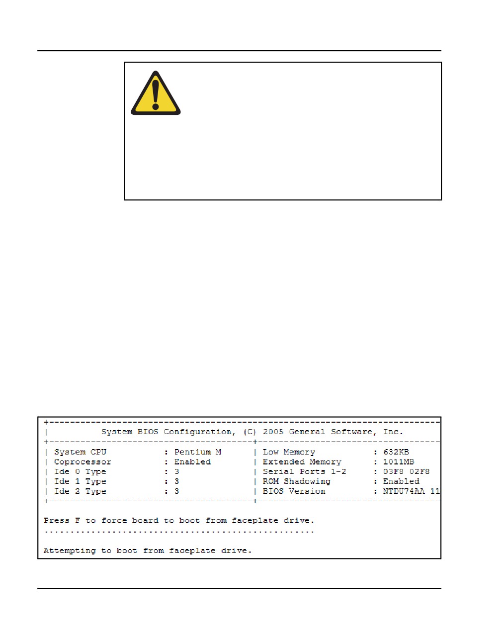
Reboot the card by pressing the RST button on the faceplate of the Call
Server. When prompted (see Figure 31), enter F to “force board to boot
from faceplate drive” (prompt may appear twice).
Figure 31
Upgrade boot sequence
NN43041-310
Standard 01.11
October 2008
Installing software on the CS 1000E
Page 119 of 466
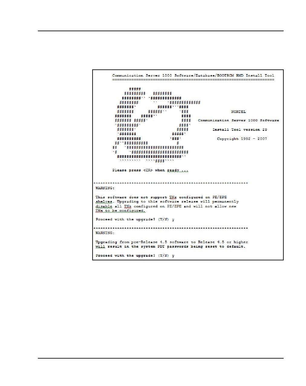
The VxWorks banner screen appears (see Figure 32 on page 119):
Figure 32
VxWorks banner
4
Enter y for both software warnings to proceed with the upgrade.
Note: PE/EPE is not applicable for this upgrade as it only applies to
large systems.
Communication Server 1000E Installation and Commissioning
Page 120 of 466
Installing software on the CS 1000E
5
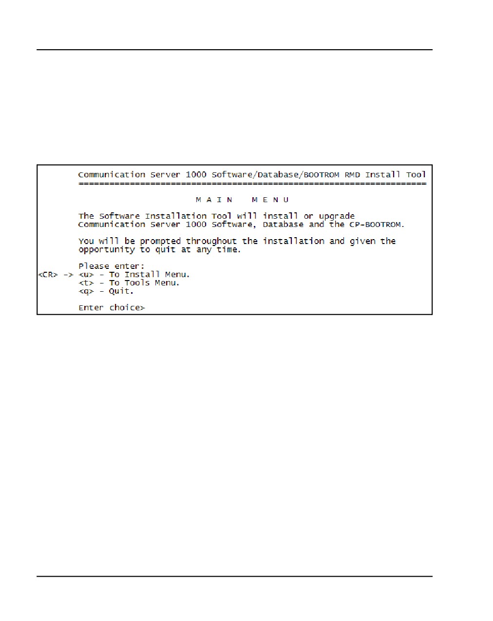
The Software Installation Tool Main Menu appears (see Figure 33 on
page 120).
Note: If the keycode files reside on a separate CF card, remove the
software CF card and insert the CF card containing the keycode files. The
keycode normally resides in the keycode folder of the OS CF card.
Figure 33
Software Installation Tool Main Menu
NN43041-310
Standard 01.11
October 2008
Installing software on the CS 1000E
Page 121 of 466
6
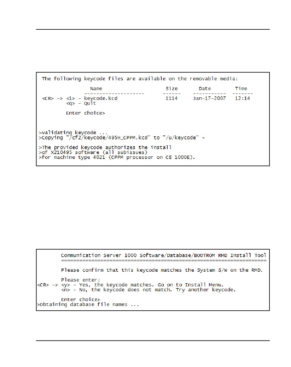
Enter <CR> or u to access the Install Menu. The following screen appears
(see Figure 34).
Figure 34
Keycode files
7
The keycode file appears in the list. Select the appropriate keycode file for
this system and install the keycode.
Note: If the CF card was exchanged, insert the CF card containing
CS 1000 Release 5.0.
8
Enter <CR> or y to confirm that the keycode matches the system software
on the RMD (see Figure 35 on page 121).
Figure 35
Keycode confirmation
Communication Server 1000E Installation and Commissioning
Page 122 of 466
Installing software on the CS 1000E
9
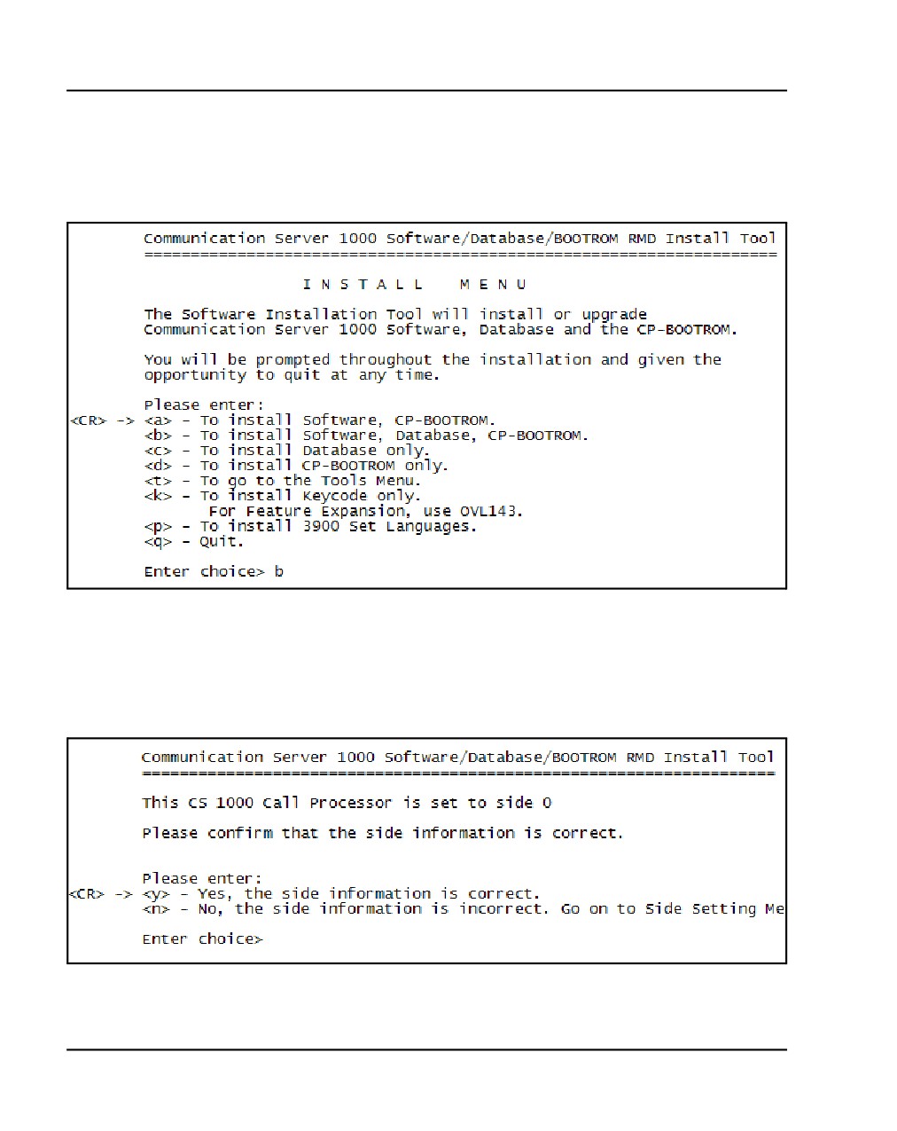
The Install Menu appears (see Figure 36 on page 122). Enter b to install
the software, database, and CP-BOOTROM.
Figure 36
Install Menu
The following screen appears (see Figure 37 on page 122):
10
Enter <CR> or y to confirm that the call processor is set to side 0.
Figure 37
Side information
NN43041-310
Standard 01.11
October 2008
Installing software on the CS 1000E
Page 123 of 466
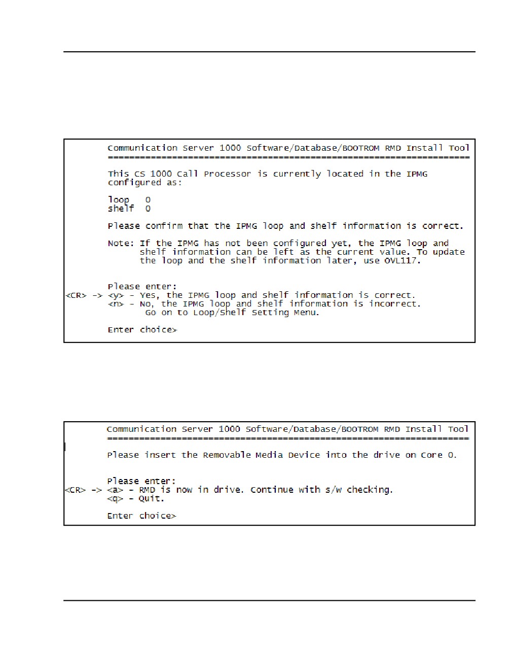
11
The location information screen appears (see Figure 38), indicating that
the call processor is located in loop 0 and shelf 0 of the IPMG. Enter <CR>
or y to confirm their location.
Figure 38
Call processor location
12
If not already present in the CF drive, insert the CF card containing
CS 1000 Release 5.0 (see Figure 39).
Figure 39
Insert RMD
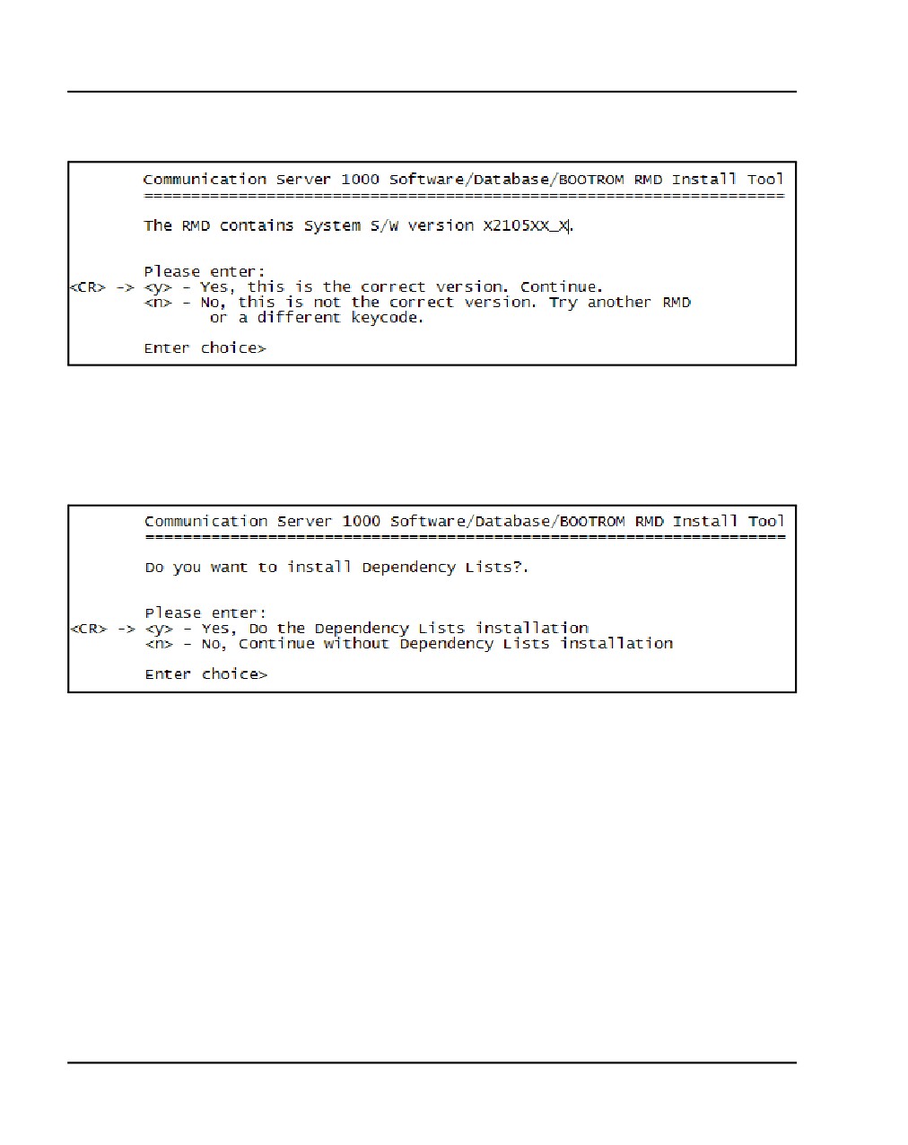
13
Enter <CR> or y to confirm that you have the correct software version
(see Figure 40 on page 124).
Communication Server 1000E Installation and Commissioning
Page 124 of 466
Installing software on the CS 1000E
Figure 40
Confirm software version
14
Enter <CR> or y to install dependency lists and continue with the upgrade
(see Figure 41 on page 124).
Figure 41
Install Dependency Lists
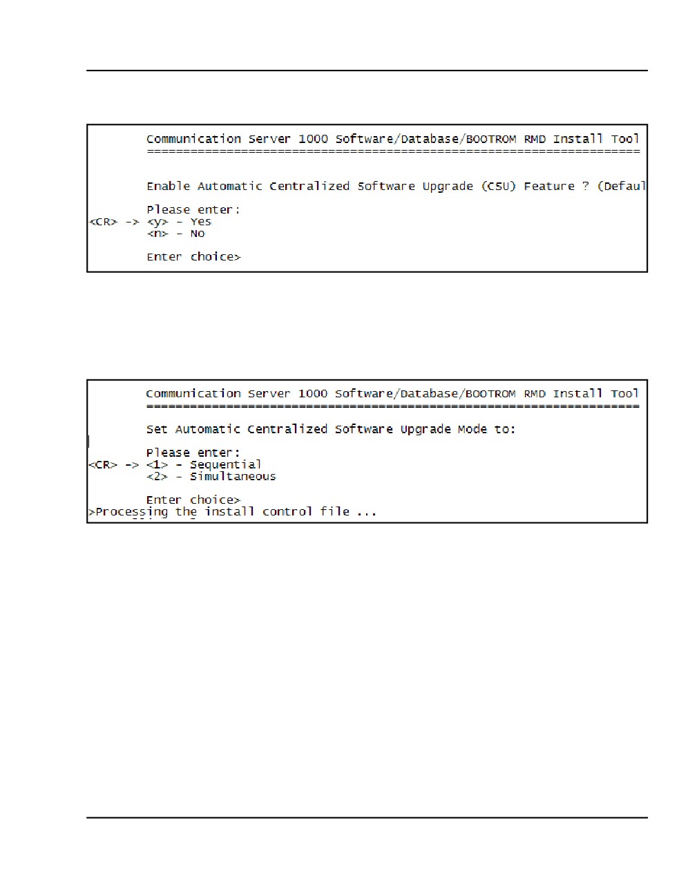
15
Enter <CR> or y (the default) to enable the Automatic Centralized
Software Upgrade (CSU) feature (see Figure 42 on page 125).
NN43041-310
Standard 01.11
October 2008
Installing software on the CS 1000E
Page 125 of 466
Figure 42
Centralized Software Upgrade
16
Set the CSU feature to Sequential by entering either <CR> or y (see
Figure 43).
Figure 43
Automatic Centralized Software Upgrade Mode
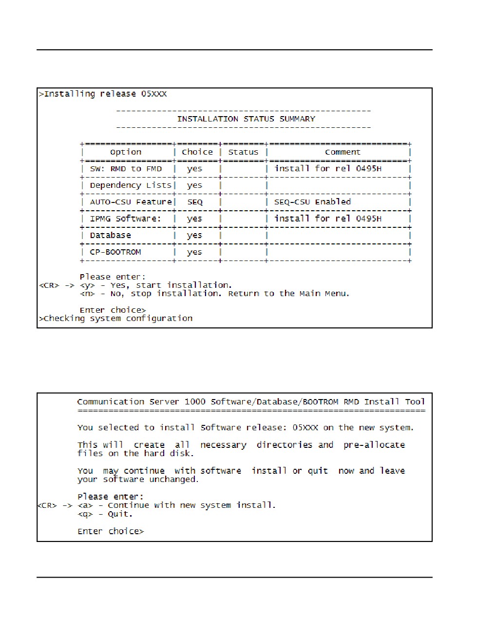
The Installation Status Summary screen appears (see Figure 44 on
page 126).
Communication Server 1000E Installation and Commissioning
Page 126 of 466
Installing software on the CS 1000E
Figure 44
Installation Status Summary
17
Enter <CR> or y to begin the installation (see Figure 45).
Figure 45
Install Tool
NN43041-310
Standard 01.11
October 2008
Installing software on the CS 1000E
Page 127 of 466
18
A prompt appears warning you that old system files will be deleted as a
result of the installation. Enter <CR> or y to continue with the installation.
19
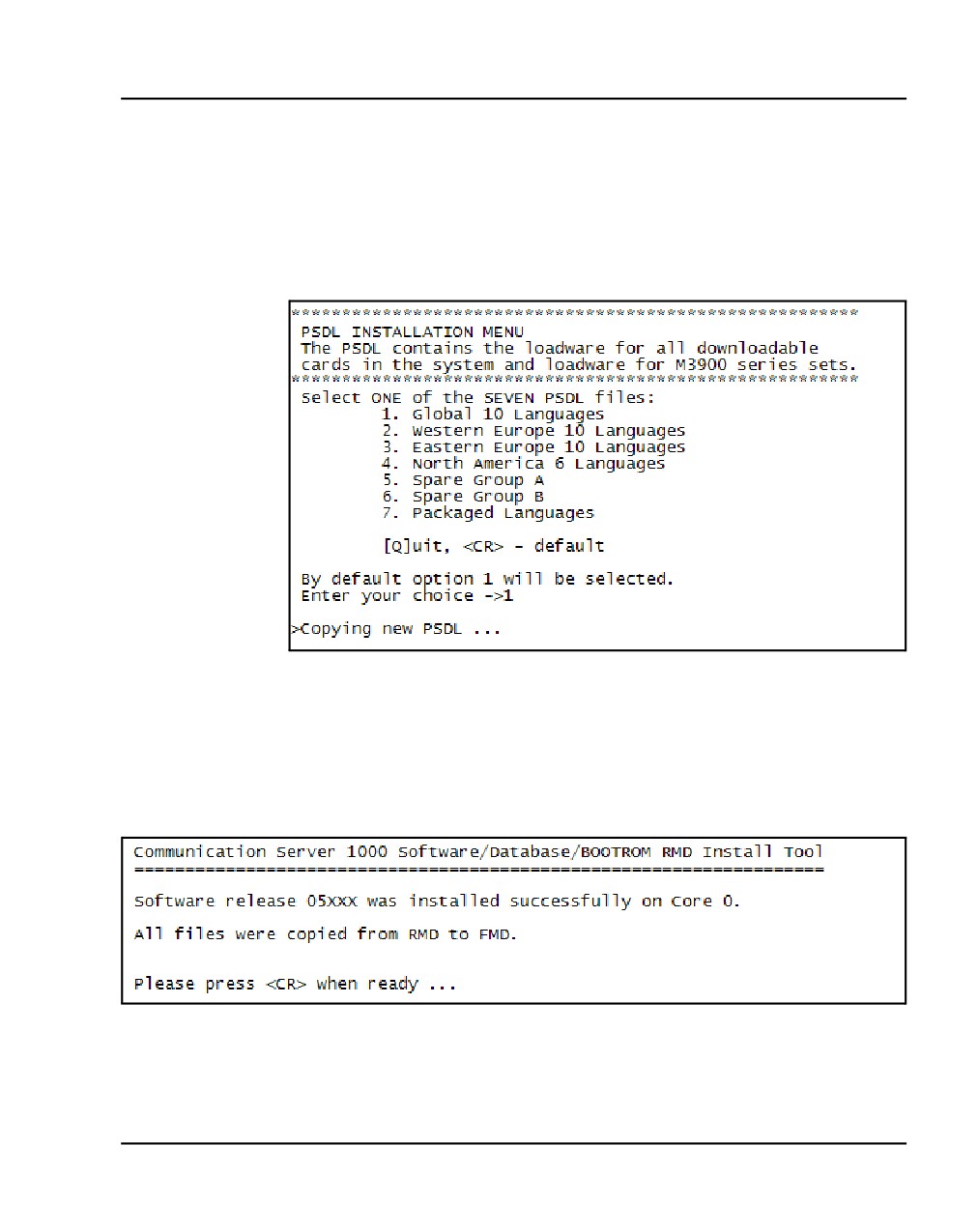
The PSDL Installation Menu appears (see Figure 46). Select the
appropriate location based on your geographical location.
Figure 46
The PSDL Installation Menu
20
Enter <CR> to continue.
A message appears indicating that the installation on Core 0 was successful
(see Figure 47).
Figure 47
Core 0 software installation complete
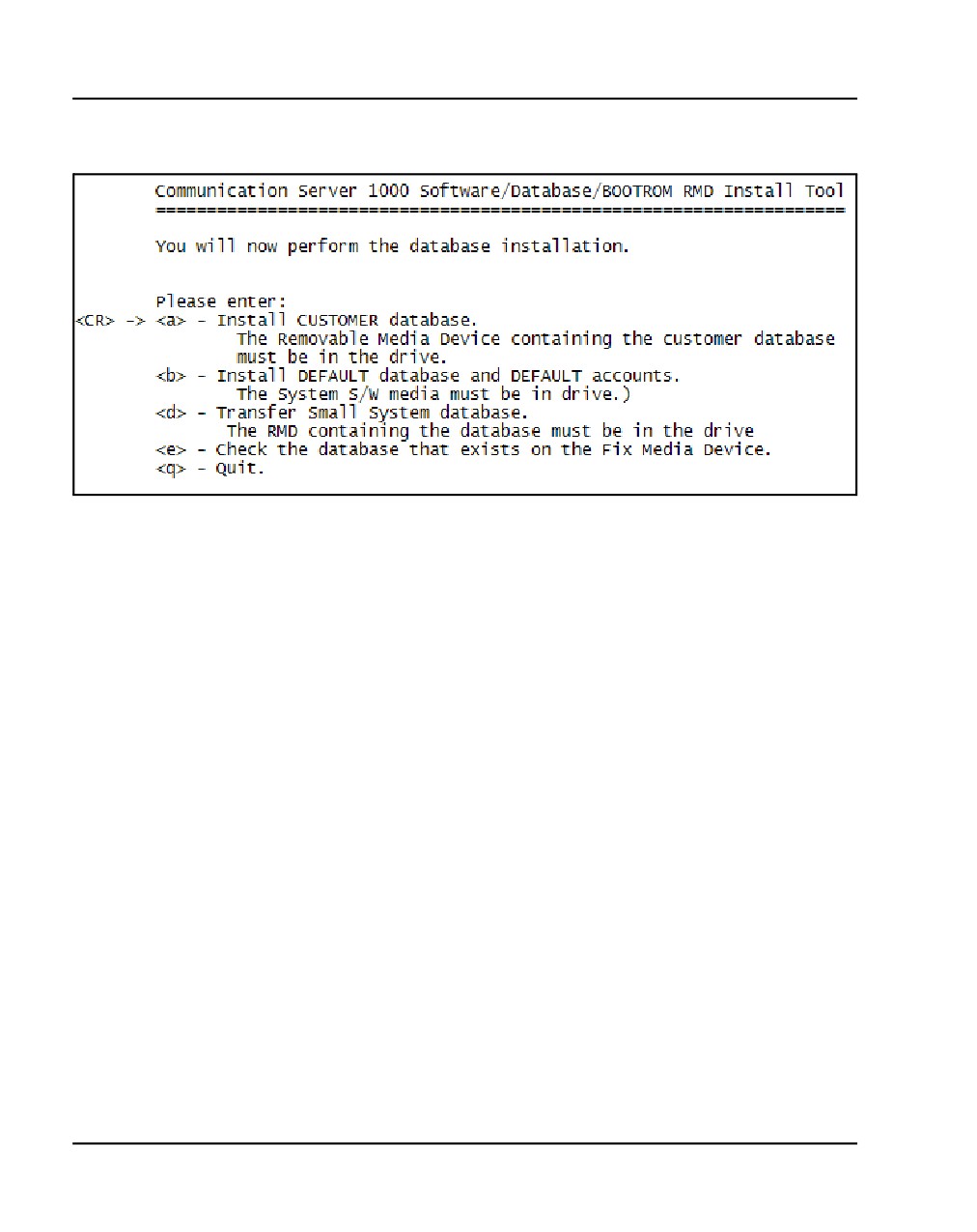
21
Enter <CR> to continue.
The following screen appears (see Figure 48).
Communication Server 1000E Installation and Commissioning
Page 128 of 466
Installing software on the CS 1000E
Figure 48
Database installation
22
Enter a.
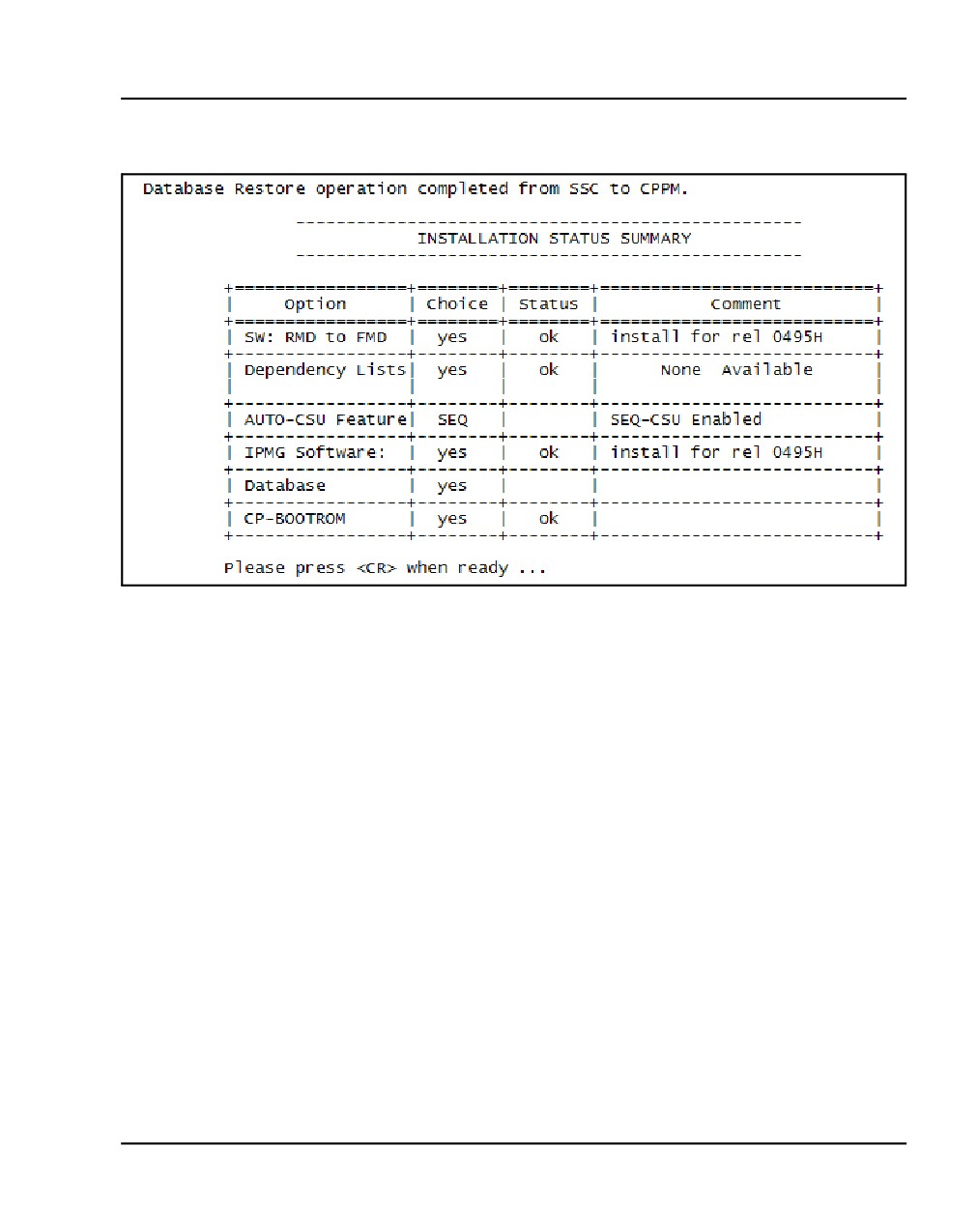
23
The Installation Status Summary screen appears, indicating that the
installation was a success (see Figure 49). Enter <CR> to continue.
NN43041-310
Standard 01.11
October 2008
Installing software on the CS 1000E
Page 129 of 466
Figure 49
Installation Status Summary
24
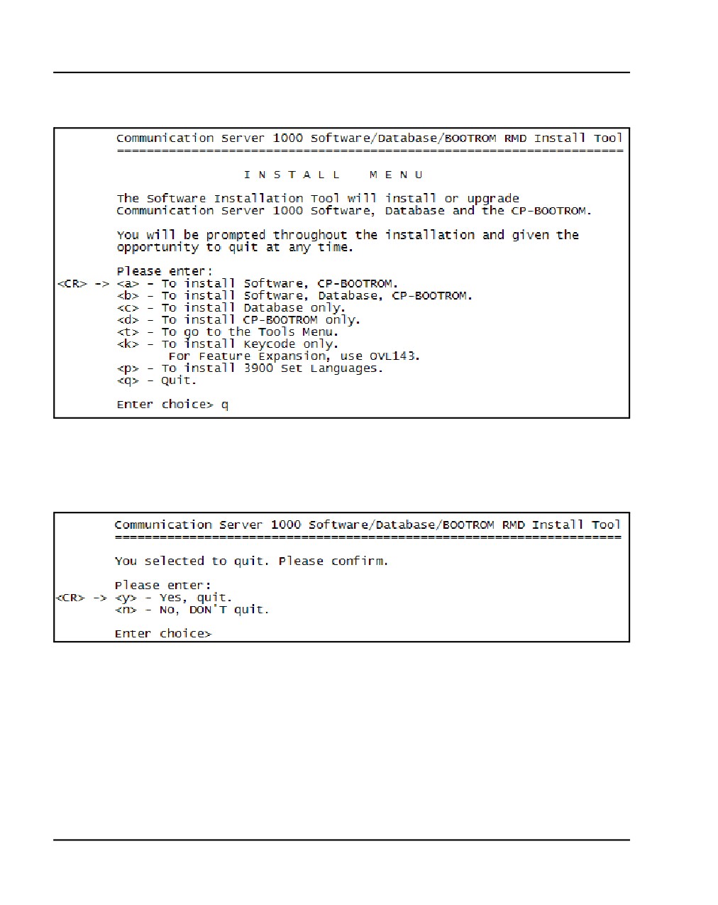
The Install Menu appears (see Figure 50 on page 130). Enter q to quit the
Install Tool.
Communication Server 1000E Installation and Commissioning
Page 130 of 466
Installing software on the CS 1000E
Figure 50
Install Menu
25
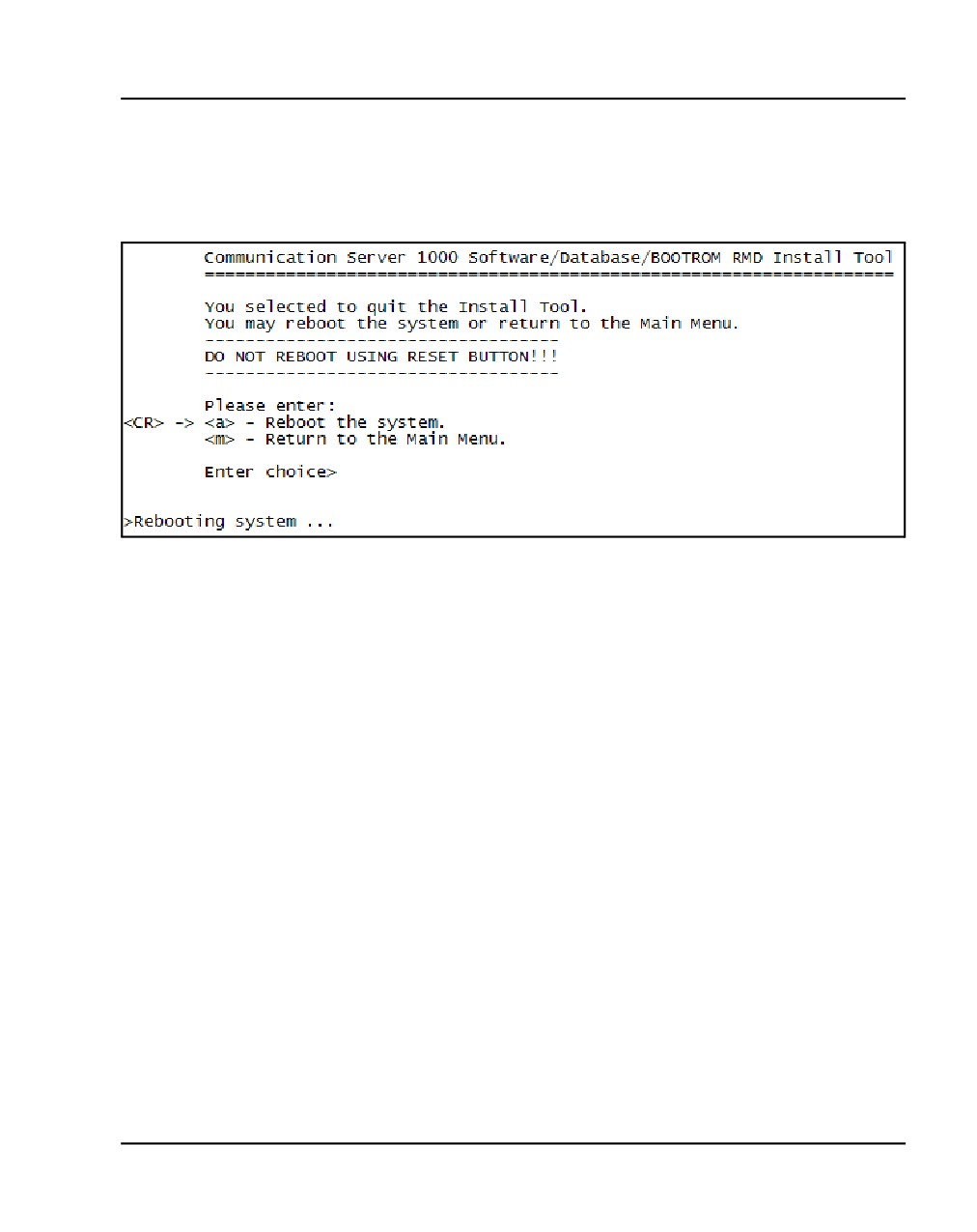
Enter <CR> or y to confirm your selection (see Figure 51).
Figure 51
Quit Install Tool
NN43041-310
Standard 01.11
October 2008
Installing software on the CS 1000E
Page 131 of 466
26
Enter <CR> or y to reboot the system (see Figure 52). Once the system
has completed its reboot, remove the CF from the faceplate.
Figure 52
System reboot
Communication Server 1000E Installation and Commissioning
Page 132 of 466
Installing software on the CS 1000E
Reconfigure I/O ports and call registers
Procedure 19
Reconfiguring I/O ports and call registers
1
Evaluate the number of call registers and 500 telephone buffers that are
configured for the system (suggested minimum values are 4500 and 1000
respectively). If changes are required, reconfigure the values in LD 17:
LD 17
Load program
500B 1000
Use 1000 as a minimum value
NCR 20000
Use 20000 as a minimum value
****
Exit program
2
Print the Configuration Record to confirm the changes made in Step 1:
LD 22
Load program
REQ PRT
Set the print option
TYPE CFN Print the configuration
****
Exit program
End of Procedure
Procedure 20
Switching call processing to the CP PM Call Server
1
Plug the CP PM Call Server port labeled ELAN into the ELAN subnet.
2
Initialize (using the init button) the CP PM card.
3
Wait for “DONE” and then “INI” messages to display before you continue.
End of Procedure
NN43041-310
Standard 01.11
October 2008
Installing software on the CS 1000E
Page 133 of 466
Test the CP PM Call Server
Procedure 21
Testing the CP PM Call Server
1
Verify that the CP PM Call Server is active.
LD 135
Load program
STAT CPU
Get the status of the CPUs
2
Check dial-tone.
3
Verify that the CP PM Call Server is active, redundant, and single.
4
Make internal, external, and network calls.
5
Check attendant console activity.
6
Check IP Peer networking for incoming and outgoing calls.
7
Check applications (CallPilot, Symposium, and so on).
End of Procedure
Install the software on the second CP PM Call Server
Procedure 22
Installing the software on the second CP PM Call Server
1
Attach the ELAN and TLAN cables to the CP PM faceplate connectors
between the CP PM Call Servers.
2
Complete procedures 22 through 27 for the second CP PM Call Server.
3
Each CP PM Call Server can be named: CP PM Call Server 1 and CP PM
Call Server 0.
Note: Do not install ELAN and TLAN cables at this time.
End of Procedure
Communication Server 1000E Installation and Commissioning
Page 134 of 466
Installing software on the CS 1000E
Verifying CP PM Call Server 0 is active
Use the following commands to verify that CP PM Call Server 0 is active.
LD 135
Load program
STAT CPU
Get the status of the CPUs
CFN
Make the system redundant
At this point, Core/Net 0 is ready to be synchronized with Core/Net 1.
Procedure 23
Making the system redundant
1
Check to see if the ELAN and TLAN cables are attached. If not, attach the
ELAN and TLAN cables to the CP PM faceplate connectors both CP PM
cards.
2
Once the synchronization of memories and drives is complete, STAT the
CPU and verify that the CPUs are in a true redundant state.
LD 135
STAT CPU
Get status of CPU and memory
****
Exit the program
NN43041-310
Standard 01.11
October 2008
Installing software on the CS 1000E
Page 135 of 466
.stat cpu
cp 0 16 PASS -- STDBY
TRUE REDUNDANT
DISK STATE = REDUNDANT
HEALTH
= 20
VERSION = Mar
3 2005, 16:26:40
Side = 0, DRAM SIZE = 512 MBytes
cp 1 16 PASS -- ENBL
TRUE REDUNDANT
DISK STATE = REDUNDANT
HEALTH = 20
VERSION = Mar
3 2005, 16:26:40
Side = 1, DRAM SIZE = 512 MBytes
3
Tier 1 and Tier 2 health of both CP PM Call Servers must be identical in
order to successfully switch service from CP PM Call Server 1 to CP PM
Call Server 0.
LD 135
STAT HEALTH Get status of CPU and memory
****
Exit the program
Communication Server 1000E Installation and Commissioning
Page 136 of 466
Installing software on the CS 1000E
.stat health
Local (Side 0, Active, Redundant):
Components without TIER 1 Health contribution:
=================================================
disp 0 15 1:In Service
sio2 0 15 1:In Service
cp 0 16:In Service
ipb 0:In Service
TIER 1 Health Count Breakdown:
=====================================
sio8 0 16 1: 0002
sio8 0 16 2: 0002
sutl 0 15: 0002
strn 0 15: 0002
xsmp 0 15 1: 0002
eth 0 16 0: 0002
Local TIER 1 Health Total: 20
NN43041-310
Standard 01.11
October 2008
Installing software on the CS 1000E
Page 137 of 466
TIER 2 Health Count Breakdown:
=======================================
ELAN 16 IP : 47.11.138.150 Health = 2
ELAN 17 IP : 47.11.138.153 Health = 2
Local AML over ELAN Total Health:4
Local Total IPL Health = 6
IPL connection history:3 3 3 3 3 3 3 3 3 3 3 3 3 3
3 3 3 3 3 3
Local TIER 2 Health Total:10
Remote (Side 1, Inactive, Redundant):
Components without TIER 1 Health contribution:
disp 1 15 1:In Service
sio2 1 15 1:In Service
cp 1 16:In Service
ipb 1:In Service
TIER 1 Health Count Breakdown:
sio8 1 16 1: 0002
sio8 1 16 2: 0002
sutl 1 15: 0002
strn 1 15: 0002
xsmp 1 15 1: 0002
eth 1 16 0: 0002
Remote TIER 1 Health Total: 20
Communication Server 1000E Installation and Commissioning
Page 138 of 466
Installing software on the CS 1000E
TIER 2 Health Count Breakdown:
=======================================
ELAN 16 IP : 47.11.138.150 Health = 2
ELAN 17 IP : 47.11.138.153 Health = 2
Remote AML over ELAN Total Health:4
Remote Total IPL health = 6
Remote TIER 2 Health Total:10
4
Get status of links to the Media Gateways (STAT IPL).
LD 135
STAT IPL
Get status of MG 1000E (IPMG)
Media Gateway 1: LINK UP
Media Gateway 2: LINK UP
Media Gateway 3: LINK UP
Media Gateway 4: LINK UP
****
Exit the program
The system now operates in full redundant mode with CP
PM Call Server 1 active.
End of Procedure
NN43041-310
Standard 01.11
October 2008
Installing software on the CS 1000E
Page 139 of 466
Complete the CP PM installation
Testing the CP PM Call Servers
Procedure 24
Testing CP PM Call Server 0
At this point in the installation, CP PM Call Server 0 is tested from active CP
PM Call Server 1. Upon successful completion of these tests, call processing
is switched and the same tests are performed on CP PM Call Server 1 from
active CP PM Call Server 0. As a final step, call processing is then switched
again to CP PM Call Server 1.
From active CP PM Call Server 1, perform the following tests on CP PM
Call Server 0:
1
Perform a redundancy sanity test:
LD 135
STAT CPU
Get status of CPU and memory
TEST CPU
Test the CPU
2
Check the LCD states
a. Perform a visual check of the LCDs.
b. Test and LCDs:
LD 135
TEST LEDs Test LEDs
DSPL ALL
c. Check that the LCD display matches the software check.
3
Test the System Utility card
LD 135
Load program
STAT SUTL Get the status of the System Utility card
TEST SUTL Test the System Utility card
Communication Server 1000E Installation and Commissioning
Page 140 of 466
Installing software on the CS 1000E
4
Test system redundancy and media devices:
LD 137
Load program
TEST RDUN Test redundancy
DATA RDUN Test database integrity
STAT FMD Status of one or both Fixed Media Devices
(FMD)
STAT RMD Status of one or both Removable Media Devices
(RMD)
5
Clear the display and minor alarms on both CP PM Call Servers:
LD 135
Load program
CDSP
Clear the displays on the cores
CMAJ
Clear major alarms
CMIN ALL Clear minor alarms
6
Check dial tone.
7
Check applications (CallPilot, Symposium, and so on)
End of Procedure
Switch call processing
Procedure 25
Switching call processing
LD 135
Load program
SCPU
Switch call processing from CP PM Call
Server 1 to CP PM Call Server 0
CP PM Call Server 0 is now the active call processor.
End of Procedure
NN43041-310
Standard 01.11
October 2008
Installing software on the CS 1000E
Page 141 of 466
Procedure 26
Testing CP PM Call Server 1
From active CP PM Call Server 0, perform these tests on CP PM Call Server
1:
1
Perform a redundancy sanity test:
LD 135
Load program
STAT CPU
Get status of CPU and memory
TEST CPU
Test the CPU
2
Check the LCD states.
a. Perform a visual check of the LCDs.
b. Test LCDs:
LD 135
Load program
TEST LCDs Test LCDs
DSPL ALL
c. Check that the LCD display matches the software check.
3
Test the System Utility card:
LD 135
Load program
STAT SUTL Get the status of the System Utility card
TEST SUTL Test the System Utility card
4
Test system redundancy and media devices:
LD 137
Load program
TEST RDUN Test redundancy
DATA RDUN Test database integrity
STAT FMD Status of one or both Fixed Media Devices
(FMD)
Communication Server 1000E Installation and Commissioning
Page 142 of 466
Installing software on the CS 1000E
STAT RMD Status of one or both Removable Media Devices
(RMD)
****
Exit the program
5
Clear the display and minor alarms on both CP PM Call Servers:
LD 135
Load program
CDSP
Clear the displays on the CP PM Call Servers
CMAJ
Clear major alarms
CMIN ALL Clear minor alarms
6
Check dial tone.
7
Check applications (CallPilot, Symposium, etc.)
End of Procedure
Switch call processing
Procedure 27
Switching call processing
LD 135
Load program
SCPU
Switch call processing from CP PM Call
Server 0 to CP PM Call Server 1
CP PM Call Server 1 is now the active call processor.
End of Procedure
NN43041-310
Standard 01.11
October 2008
Installing software on the CS 1000E
Page 143 of 466
Perform a customer backup data dump (installation release)
Procedure 28
Performing a data dump to backup the customer database:
1
Log in to the system.
2
Insert a CF card into the active CP PM Call Server RMD slot to back up
the database.
3
Load the Equipment Data Dump Program (LD 43). At the prompt, enter:
LD 43
Load program.
EDD
4
When “EDD000” appears on the terminal, enter:
EDD
Begin the data dump.
CAUTION — Service Interruption
Loss of Data
If the data dump is not successful, do not continue;
contact your technical support organization. A data dump
problem must be corrected before proceeding.
5
When “DATADUMP COMPLETE” and “DATABASE BACKUP
COMPLETE” appear on the terminal, enter:
****
Exit program
The installation is now complete.
End of Procedure
Configuring initial IP configuration data on MGC
Note: Coordinate all Nars/Bars and NRS changes to ensure that your
cutover plan is designed for minimum downtime.
Communication Server 1000E Installation and Commissioning
Page 144 of 466
Installing software on the CS 1000E
The MGC must be given a superloop and shelf reference on the Call Server
(see Table 13).
Table 13
MGC superloop configuration
Loop
Shelf
IPMG #
000
0
1
000
1
2
004
0
3
004
1
4
008
0
5
096
0
49
096
1
50
Procedure 29
Configuring the MGC on the Call Server
Note: Initial configuration of the MGC is command line ONLY.
The MGC is shipped with “gold” software in onboard flash memory. If
centralized software upgrade is enabled on the Call Server, the MGC is
upgraded automatically (or it can be upgraded manually through LD 143).
There are two ways to enter mgcsetup:
•
If no IP information exists on the MGC, it will boot directly into the
setup menu.
•
If IP information does exist, the prompt “To invoke install menu or
bypass loadware upgrade enter CONTROL-I” appears.
NN43041-310
Standard 01.11
October 2008
Installing software on the CS 1000E
Page 145 of 466
The MGC Shells can be accessed using the following commands:
•
<CTRL>O<CTRL>A<CTRL>M, (provide OAM username and
password to access OAM shell)
•
<CTRL>L<CTRL>D<CTRL>B, (provide LDB username and
password to access LDB)
1
Enter network IP information at the MGC setup menu:
Please define the data networking parameters for this
MG 1000E now.
Hostname:
MGC_N313
(optional)
ELAN IP:
0.0.0.0
192.168.3.33
ELAN subnet mask:
0.0.0.0
255.255.255.0
ELAN gateway IP:
192.168.3.1
TLAN IP:
0.0.0.0
192.168.19.33
TLAN subnet mask:
0.0.0.0
255.255.255.0
TLAN gateway IP :
192.168.19.1
Primary CS Hostname:
CS1000E_N313
(optional)
Primary CS IP:
192.168.3.32
Leading Secondary CS Hostname:<enter>
Leading Secondary CS IP:
0.0.0.0
Secondary CS Hostname:
<enter>
Secondary CS IP:
0.0.0.0
Communication Server 1000E Installation and Commissioning
Page 146 of 466
Installing software on the CS 1000E
2
Enter port and security parameters, if required:
Change MGC advanced parameters? (y/[n]) : y
TLAN is set to auto negotiate, change? (y/[n]) : y
Note: Turning off auto negotiate on the TLAN
: will default it to 100Mbps full duplex.
Set TLAN to auto negotiate? ([y]/n) : y
ELAN is set to auto negotiate, change? (y/[n]) : y
Note: Turning off auto negotiate on the ELAN
: will default it to 100Mbps full duplex.
Set ELAN to auto negotiate? ([y]/n) : y
ELAN security Disabled, change? (y/[n]) : y
Enable ELAN security ? (y/[n]) : y
Enter security level OPTI, FUNC or FULL : opti
Note: Spaces ~ * ` @ [ ] and # are not supported in
passwords.
Please input PSK(16-32 chars): (input is not echoed)
Strength of PSK: Weak
Please reenter PSK(16-32 chars): (input is not echoed)
3
Review the network information and enter “y” to confirm.
You have entered the following parameters for this MG
1000E:
Hostname
: MGC_N313
ELAN IP
: 192.168.3.33
ELAN subnet mask
: 255.255.255.0
ELAN gateway IP
: 192.168.3.1
TLAN IP
: 192.168.19.33
TLAN subnet mask
: 255.255.255.0
TLAN gateway IP
: 192.168.19.1
Primary CS Hostname
: CS1000E_N313
Primary CS IP
: 192.168.3.32
Alternate CS 1 Hostname :
Alternate CS 1 IP
: 0.0.0.0
Alternate CS 2 Hostname :
Alternate CS 2 IP
: 0.0.0.0
NN43041-310
Standard 01.11
October 2008
Installing software on the CS 1000E
Page 147 of 466
TLAN set to auto negotiate.
ELAN set to auto negotiate.
ELAN security Enabled, level is Optimized Security
Is this correct? (y/n/[a]bort) : y
4
IP changes require a reboot. Enter “y” at the prompt.
Do you want to continue? (y/n/[a]bort) : y
reboot(-1) has been called...
Following the reboot, the MGC connects to the CS and downloads the
remaining configuration information.
If centralized software upgrade has been enabled, the MGC will upgrade its
loadware by downloading it from the CS.
Once the MGC has registered, the LED display will show the superloop and
shelf (for example: 4 0) of the IPMG. Otherwise, it will show “UNRG.”
Configuring the IPMG zone and IP address
The next step in the process involves configuring the IPMG zone and IP
address in Overlay 97 on the Call Server.
Note: This procedure may be performed through Element Manager
following the installation of the Signaling Server. To configure an IPMG
using Element Manager see Procedure 48 on page 240.
1
Log into Overlay 97 to configure the MGC that will register to the call
server:
>LD 97
SCSYS000
MEM AVAIL: (U/P): 103979814
USED U P: 230475 59531
TOT: 104269820
REQ prt
TYPE supl
SUPL
SUPL SUPT SLOT XPEC0
XPEC1
IPMG
ZONE0/1 IPR0/1
Communication Server 1000E Installation and Commissioning
Page 148 of 466
Installing software on the CS 1000E
000 IPMG ---- -- - -
-- - -
001
---
------------
002
---
------------
004 IPMG ---- -- - - -- - -
003
---
------------
004
---
----------
008 IPMG ---- -- - - -- - -
005
---
------------
006
---
------------
096
----
---- VIRTUAL -- - -
---
--- -
---
----------
100
----
---- VIRTUAL -- - -
---
--- -
---
----------
104
----
---- VIRTUAL -- - -
---
--- -
---
----------
112
----
---- VIRTUAL -- - -
---
--- -
---
----------
REQ chg
TYPE supl
SUPL 0
SLOT
SUPT ipmg
IPR0 <IP address for shelf 0>
IPR1 <IP address for shelf 1>
IPMG_TYP0 mgc
ZONE0 1
**** ALL VWG CHANNELS MUST BE OUTED AND RECONFIGURED AFTER
IPMG ZONE CHANGE
DES0
-CE
NN43041-310
Standard 01.11
October 2008
Installing software on the CS 1000E
Page 149 of 466
Rebooting the MGC
The MGC reboots and registers with the Call Server.
Found device : INTEL 82365SL
Engcode:NTDW60BA REL 08
ELAN mac address is:00:13:65:ff:ee:ed
TLAN mac address is:00:13:65:ff:ee:ec
RESET reason: Hard Reset.
Daughter board 1:NTDW62AA R02
00:13:65:ff:f8:fd.
Daughter board 2:NOT INS
VxWorks System Boot
Copyright 1984-2005 Wind River Systems, Inc.
CPU: Chagall
Version: VxWorks5.5.1
Bootcode version: MGCBAA20
auto-booting...
Loading MSP from CF...1375736
Booting ARM0 (MSP) at 0x00000100 ...
Loading CSP from CF...6643712 + 5849088
Booting ARM1 (CSP) at 0x80010000 ...
Found device : INTEL 82365SL
Loading symbol table from /p/mainos.sym ...done
Loadware upgrade
If the MGC loadware is out of date (compared to the loadware on the Call
Server), an upgrade of the loadware occurs based on the Centralized Upgrade
setting defined during the software install and the values set in overlay 143.
The default values are set so that the upgrade starts automatically once
registration is achieved with the Call Server.
There are six pieces of loadware that are updated on the MGC. These updates
are downloaded from the Call Server.
Communication Server 1000E Installation and Commissioning
Page 150 of 466
Installing software on the CS 1000E
-> Received an upgrade request. Preparing MGC for upgrade.
Auto commit option has been enabled.
Upgrade of CSP loadware initiated.
OMM: IP link is UP between Primary Call Server and MGC 1
Upgrade of MSP loadware initiated.
Upgrade of APP loadware initiated.
Upgrade of FPGA loadware initiated.
Upgrade of DBL1 initiated.
-> 0x86f8bc30 (tMGCInst):
Upgrading FPGA Loadware...
logTask: 1 log messages lost.
0x86f8bc30 (tMGCInst): Programming FPGA ...
0x86f8bc30 (tMGCInst): FPGA Upgrade completed.
0x86f8bc30 (tMGCInst): Upgrading Application Loadware ...
0x86f8bc30 (tMGCInst): Gold CSP image upgraded
0x86f8bc30 (tMGCInst): mgcBootLineFix:fixing the bootline
0x86f8bc30 (tMGCInst): Upgrade Application Loadware
completed
0x86f8bc30 (tMGCInst): Rebooting MGC to take the upgrade
in effect.
At this point the IPMGs synchronize with the Call Server.
End of Procedure
NN43041-310
Standard 01.11
October 2008
172
Page 151 of 466
Configuring the CS 1000E CP PM
Call Server
Contents
This section contains information on the following topics:
Introduction
152
Configuring login IDs and passwords
153
Enabling the multi-user option
156
Configuring pseudo-terminals (PTYs)
157
Checking PTY status
159
Configuring Virtual Tone and Conference Circuits
160
Configuring the MG 1000E Bandwidth Management Zones
161
Configuring the MG 1000E ports
163
Configuring Digitone Receivers
164
Configuring Tone Detectors
165
Logging in to Element Manager
165
Importing preconfigured IP telephony files
168
Reviewing and submitting IP telephony node configuration files
170
Adding a Follower Signaling Server to an IP telephony node
170
Performing a datadump
170
Communication Server 1000E Installation and Commissioning
Page 152 of 466
Configuring the CS 1000E CP PM Call Server
Introduction
The CS 1000E system requires the configuration of an IP telephony node.
The configuration data is stored in the BOOTP.TAB and CONFIG.INI files
on the CS 1000E. Copies of both files are maintained on each node
component (Signaling Server and Media Card).
The preconfigured IP telephony configuration files from the leader Signaling
Server must be imported. These files are saved on the CS 1000E as:
•
c:/u/db/node/nodex.cfg where x is the node number
•
c:/u/db/node/nodex.btp where x is the node number
IMPORTANT!
Do not attempt to alter the configuration files either manually or with
OTM’s ITG or IP Phone management. Use Element Manager only.
The node database files are backed up along with the customer database using
the LD 43 EDD command.
This chapter contains the following procedures:
•
Procedure 30: "Configuring login IDs and passwords" on page 153
•
Procedure 31: "Enabling the multi-user option" on page 156
•
Procedure 32: "Configuring pseudo-terminals (PTYs)" on page 157
•
Procedure 33: "Checking PTY status" on page 159
•
Procedure 34: "Configuring MG 1000E Bandwidth Management Zone"
on page 161
•
Procedure 35: "Launching Element Manager" on page 166
•
Procedure 36: "Importing an existing node" on page 168
•
Procedure 37: "Performing a datadump using Element Manager"
on page 170
NN43041-310
Standard 01.11
October 2008
Configuring the CS 1000E CP PM Call Server Page 153 of 466
Configuring login IDs and passwords
Note: You must be logged in as a user with admin2 level privileges in
order to change the default username and password.
For increased security:
•
Change the default login username and password.
The default login is username admin1 and password 0000, as used
throughout this guide.
•
Configure the Limited Access Password (LAPW) IDs and passwords.
Follow Procedure 30 to configure login IDs and passwords.
Procedure 30
Configuring login IDs and passwords
1
Enter the command:
LD 17
CFN000
MEM AVAIL: (U/P): 1015918 USED U P: 138773 24956
TOT:1179647
DISK RECS AVAIL: 486
TMDI D-CHANNELS AVAIL: 0 USED: 0 TOT: 0
DCH AVAIL: 80 USED: 0 TOT: 80
AML AVAIL: 15 USED: 1 TOT: 16
2
Enter the command:
REQ CHG
3
Enter the command:
PSWD_COMP
<enter to accept default or set to required setting>
FPC
<enter to accept default or set to required setting>
LOUT
<enter to accept default or set to required setting>
FLTH
<enter to accept default or set to required setting>
Communication Server 1000E Installation and Commissioning
Page 154 of 466
Configuring the CS 1000E CP PM Call Server
LOCK
<enter to accept default or set to required setting>
FLTA
<enter to accept default or set to required setting>
AUDT
<enter to accept default or set to required setting>
LLID
<enter to accept default or set to required setting>
4
Enter the command:
ACCOUNT_REQ new
5
Enter the command:
PWD_TYPE pwd2 (pwd1, pwd2, lapw are options)
6
Enter the command:
USER_NAME kattest (username)
7
Enter the command:
PASSWORD (userpassword)
8
Enter the command:
CONFIRM (confirm password)
9
Enter the command:
ACCT yes (yes for pdt access, default for no pdt access
10
Enter the command:
PDT pdt2 (pdt1 or pdt2)
11
Enter the command:
ACCOUNT_REQ new
12
Enter the command:
PWD_TYPE lapw
13
Enter the command:
PWTP ovly
14
Enter the command:
USER_NAME kattest (username)
NN43041-310
Standard 01.11
October 2008
Configuring the CS 1000E CP PM Call Server
Page 155 of 466
15
Enter the command:
PASSWORD (userpassword)
16
Enter the command:
CONFIRM (confirm password)
17
Enter the command:
OVLA 10 11
18
Enter the command:
OVLA all
19
Enter the command:
OVLA
20
Enter the command:
Cust 0
21
Enter the command:
TEN
22
Enter the command:
CUST
23
Enter the command:
HOST
24
Enter the command:
MAT
25
Enter the command:
OPT
26
Enter the command:
PDT
PWD ACCOUNT SETTINGS SAVED
End of Procedure
Communication Server 1000E Installation and Commissioning
Page 156 of 466
Configuring the CS 1000E CP PM Call Server
Enabling the multi-user option
Follow Procedure 31 to enable the multi-user option.
Procedure 31
Enabling the multi-user option
1
Enter the command:
LD 17
System response:
CFN000
MEM AVAIL: (U/P): 1015918 USED U P: 138773 24956
TOT: 1179647
DISK RECS AVAIL: 486
TMDI D-CHANNELS AVAIL: 0 USED: 0 TOT: 0
DCH AVAIL: 80 USED: 0 TOT: 80
AML AVAIL: 15 USED: 1 TOT: 16
2
Enter the command:
REQ chg
3
Enter the command:
TYPE ovly
4
Enter the command:
MULTI_USER on
System response:
MEM AVAIL: (U/P): 1015893 USED U P: 138773 24981
TOT: 1179647
DISK RECS AVAIL: 486
TMDI D-CHANNELS AVAIL: 0 USED: 0 TOT: 0
DCH AVAIL: 80 USED: 0 TOT: 80
AML AVAIL: 15 USED: 1 TOT: 16
5
Enter the command:
REQ ****
End of Procedure
NN43041-310
Standard 01.11
October 2008
Configuring the CS 1000E CP PM Call Server Page 157 of 466
Configuring pseudo-terminals (PTYs)
CS 1000E provides two ports (COM1 and COM2) on the CPU. A Terminal
Server is used to provide additional serial ports for specific applications, such
as, CTY, MCT, PMS, and TRF. Each configured Terminal Server serial port
automatically starts an rlogin session with a user ID to a dedicated pseudo
(PTY) port in the CS 1000E system. Nortel recommends configuring at least
two PTYs for general use (rlogin sessions with no user ID). In practice, a
maximum of 14 PTYs can be used, leaving 2 TTYs for COM1 and COM2 on
the CPU card. Login to PTY is case sensitive.
Every PTY configured is given a user ID "PTYx", where x is the port number
assigned to the PORT prompt. If no input is entered for the PORT prompt, the
default value is the same as the TTY number. Nortel recommends using the
default value for easy management. When an rlogin session is initiated with
a user ID, the Call Server searches for a free PTY with a matching user ID.
The search starts with the highest configured PTY number and progresses in
descending order of the PTY number. If no free PTY with a matching user ID
is found, the connection is refused. In this case, TTY012 message is printed
on the administration terminal. When an rlogin session is initiated with no
user ID specified, the Call Server searches for a free PTY. The search starts
from the lowest configured PTY number and progresses in ascending order
of the PTY number. The first available PTY is used to open the rlogin session.
In order to minimize the probability of having a PTY configured for a specific
application being used for general rlogin sessions, PTYs of specific
applications are configured to start with the highest TTY number, such as 15,
and progress in descending order. PTYs for general use are configured to start
with the lowest number and progress in ascending order.
Follow Procedure 32 to configure pseudo-terminals.
Procedure 32
Configuring pseudo-terminals (PTYs)
Nortel recommends that at least two PTYs be configured. A maximum of four
PTYs can be allocated on a CS 1000E system.
1
Enter the command:
LD 17
Communication Server 1000E Installation and Commissioning
Page 158 of 466
Configuring the CS 1000E CP PM Call Server
System response:
CFN000
MEM AVAIL:(U/P):1019254 USED U P:138012 22381
TOT:1179647
DISK RECS AVAIL: 491
TMDI D-CHANNELS AVAIL: 0 USED: 0 TOT: 0
DCH AVAIL: 80 USED: 0 TOT: 80
AML AVAIL: 15 USED: 1 TOT: 16
2
Enter the command:
REQ CHG
3
Enter the command:
TYPE CFN
4
Enter the command:
ADAN NEW TTY <x>
Where:
<x> = an available TTY number (0-15)
5
Enter the command:
TTY_TYPE PTY
6
Enter the command:
PORT <y>
Where:
<y> = an available PTY port (0-7)
7
Enter the command:
DES <z>
Where:
<z> = designator (for example, “““ether
1”)
8
Enter the command:
FLOW NO
9
Enter the command:
USER MTC BUG SCH
NN43041-310
Standard 01.11
October 2008
Configuring the CS 1000E CP PM Call Server Page 159 of 466
10
Enter the command:
TTYLOG NO
11
Enter the command:
BANR YES
System response:
MEM AVAIL: (U/P):1019130 USED U P: 138064 22453
TOT: 3555327
DISK RECS AVAIL: 491
TMDI D-CHANNELS AVAIL: 0 USED: 0 TOT: 0
DCH AVAIL: 80 USED: 0 TOT: 80
AML AVAIL: 15 USED: 1 TOT: 16
ADAN DATA SAVED
12
Enter the command:
ADAN ****
End of Procedure
Checking PTY status
Follow Procedure 33 to check the PTY status.
Procedure 33
Checking PTY status
Pseudo-terminals show enabled only if you are using them.
1
Enter the command:
LD 37
2
Enter the command:
STAT
System response:
TTY 0: ENBL DES: ...
TTY 1: ENBL DES: ...
TTY 2: ENBL DES: ...
TTY 3: ENBL DES: ...
TTY 12: DSBL DES: ether 1
Communication Server 1000E Installation and Commissioning
Page 160 of 466
Configuring the CS 1000E CP PM Call Server
TTY 13: DSBL DES: ether 2
TTY 14: DSBL DES: ether 3
3
Enter the command:
****
4
Perform an EDD to save your changes.
End of Procedure
Configuring Virtual Tone and Conference Circuits
Virtual Tone and Conference Circuits must be defined for use by each
MG 1000E. Use LD 17 to add MGTDS and MG Conference loops. The
Virtual Tone and Conference Circuits in the same MG 1000E must occupy
contiguous double loops. For easy management, Nortel recommends to start
the MGTDS and MG Conference loops from a loop number high enough (for
example, 60) to leave enough superloop number for all MG 1000E
superloops.
LD 17 - Add Virtual Tone and Conference loops.
Prompt
Response
Comment
REQ
CHG
Change existing data
TYPE
CEQU
Common Equipment
MGTDS
X
(x=superloop number)
IPMG
a b
(a=loop of MG, b=shelf of MG)
MGCONF
X
(x=superloop number)
IPMG
a b
(a=loop of MG, b=shelf of MG)
NN43041-310
Standard 01.11
October 2008
Configuring the CS 1000E CP PM Call Server Page 161 of 466
Configuring the MG 1000E Bandwidth Management Zones
Follow Procedure 34 for configuring bandwidth management zones.
Procedure 34
Configuring MG 1000E Bandwidth Management Zone
1
Enter LD 117 and press <cr>.
2
Enter NEW ZONE 0, to create a new zone with default parameters.
Note: LD 117 also includes DIS and ENL commands to disable or enable
a zone. When you create a zone, its default state is enabled. See LD 117
- Bandwidth management zone commands on page 162.
3
Print zone and bandwidth information using PRT INTRAZONE or PRT
INTERZONE.
4
Exit from LD 117 by entering the command: ****
Communication Server 1000E Installation and Commissioning
Page 162 of 466
Configuring the CS 1000E CP PM Call Server
LD 117 - Bandwidth management zone commands
Command
Description
NEW ZONE xxx p1 p2 p3 p4 p5
Create a new zone, where:
xxx = zone number = (0) - 255.
p1 = Intrazone available bandwidth
= 0 - (10 000) - 100 000 (Kbps)
p2 = Intrazone preferred strategy
= (BQ for Best Quality) or BB for Best Bandwidth
p3 = Interzone available bandwidth
= 0 - (10 000) - 100 000 (Kbps)
p4 = Interzone preferred strategy
= BQ for Best Quality or BB for Best Bandwidth
p5 = Zone resource type
= (shared) or private
NEW ZONE xxx
Create a new zone with default values for the parameters:
p1 = 10 000 (Kbps)
p2 = BQ
p3 = 10 000 (Kbps)
p4 = BQ
p5 = shared
CHG ZONE xxx p1 p2 p3 p4 p5
Change parameters of a zone. All parameters, including
those that are unchanged, must be re-entered.
OUT ZONE xxx
Remove a zone.
DIS ZONE xxx
Disable a zone. When a zone is disabled, no new calls
are established inside, from, or toward this zone.
ENL ZONE xxx
Enable a zone.
PRT ZONE xxx
Print zone and bandwidth information.
End of Procedure
NN43041-310
Standard 01.11
October 2008
Configuring the CS 1000E CP PM Call Server Page 163 of 466
The type of any Bandwidth Management Zone for MG 1000E with
conference resources configured must be shared.
Distortion in Music is expected when G.729AB codec is used. Hence the
Interzone and the Intrazone policies for an MG 1000E Bandwidth
Management Zone should have Best Quality to give preference to G711
codec to minimize of occurrence of music distortion.
IMPORTANT!
Currently, the CS 1000E only supports Recorded Announcement
Broadcast and Music Broadcast.
Ensure that the bandwidth provisioned is adequate to provide the acceptable
blocking level of the resources in the MG 1000E. Refer to the
Communication Server 1000E: Planning and Engineering (NN43041-220)
for details.
Configuring the MG 1000E ports
IP addresses must be configured on the CP PM Call Server for each
MG 1000E in the system. Use LD 97 to configure the MG 1000E ports.
LD 97 - Configuring the MG 1000E ports
Prompt
Response
Comment
REQ
CHG
Change existing data
TYPE
SUPL
Superloop
SUPL
<x>
Superloop for gateway
SLOT
<x>
Default
SUPT
IPMG
MG 1000E
IPRO
xx.xx.xx.xx
IP address of for Media Gateway
ZONE0
x
Zone for Media Gateway
Communication Server 1000E Installation and Commissioning
Page 164 of 466
Configuring the CS 1000E CP PM Call Server
Configuring Digitone Receivers
Digitone Receivers must be configured in each MG 1000E if any analog
terminals or trunks are equipped. The loop of the Digitone Receivers is the
superloop of the MG 1000E. The first MG 1000E in the superloop is on shelf
0, and the second MG 1000E’s on shelf 1. Sixteen units of DTMF tone
detection (DTR) are integrated within the controller (SSC) circuitry, or eight
Digitone Receiver units can be configured on each of card 14 and card 15.
These Digitone Receiver units are built in on the SSC card in the MG 1000E.
No additional hardware is required. If Digitone Receivers units are
configured in any other card slots, a receiver hardware pack must be equipped
in the slot. If no hardware is equipped, the unequipped receiver units may be
allocated during call processing, resulting in call failure.
Any additional tone signaling resources must be added and configured as IPE
cards.
Configure Digitone Receivers in LD 13.
LD 13 - Configure the Digitone Receivers
Prompt
Response
Comment
REQ
NEW CHG
Add or change the existing data.
TYPE
a...a
Type of data block (a...a = DTR, MFC, MFE, MFK5, MFK6,
or MFR)
TN
l s c u
Terminal Number
l = loop for CS 1000E system. MG 1000E requiring Digitone
Receivers.
s = 0 or 1
c = 14 or 15 to access the integrated MG 1000E tone
circuits
u = 0-7 DTMF detectors (DTR)
0-3 MFR, MFC, MFE, MFK5, MFK6 units on card 15
NN43041-310
Standard 01.11
October 2008
Configuring the CS 1000E CP PM Call Server Page 165 of 466
Configuring Tone Detectors
Tone Detectors, when required, are configured in a manner similar to that for
Digitone Receivers. The SSC card in the MG 1000E provides four units of
Multifrequency Senders and Receivers. These units are configured on card 15
of the MG 1000E. In addition Multifrequency Transmit Level codes (MFTL0
and MFTL1) must be configured in LD 97.
LD 97 - Configure Tone Detectors
Prompt
Response
Comment
REQ
CHG
Change existing data
TYPE
SYSP
System Parameters for Peripheral equipment)
MFLT0
(0)-15
Multifrequency transmit level code for Identifier 0 for
MG 1000E
MFLT1
(0)-15
Multifrequency transmit level code for Identifier 1 for
MG 1000E
Logging in to Element Manager
To log in to Element Manager, follow the steps in Procedure 35 on page 166.
Element Manager supports Microsoft TM Internet Explorer 6.0.2600 for
Windows operating systems.
Before following this procedure, see Signaling Server: Installation and
Commissioning (NN43001-312) for information about setting up a browser
for optimal performance of Element Manager.
Communication Server 1000E Installation and Commissioning
Page 166 of 466
Configuring the CS 1000E CP PM Call Server
Note: This procedure requires Service Pack 1 and Java Runtime
environment.
Procedure 35
Launching Element Manager
1
Open the web browser.
2
Enter the Signaling Server Node IP address in the Address Bar of the
browser window, and press Enter on the keyboard.
Note: The ELAN network interface IP address may be required, instead
of the Node IP address, to access the Element Manager login web page
in secure environments.
3
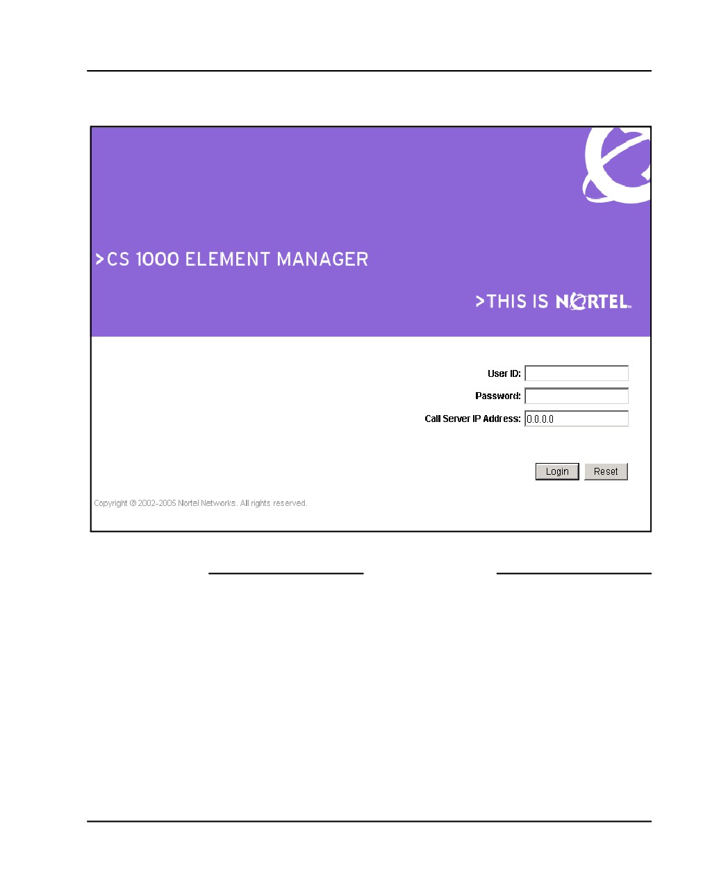
Element Manager opens with the Login web page (see Figure 53).
Note: If a security certificate has been correctly installed, and the usage
rule set to “UserChoice”, the user will have the option of logging in using
Secure mode. If the usage rule is set to “Always”, the user will be
redirected to the https site, and a warning message will appear.
a. Enter a valid User ID and Password combination.
Note: A valid User ID and Password combination is one which is
defined on the Call Server.
The IP Address of the Call Server appears in the Call Server IP
Address field.
b. Click Login.
NN43041-310
Standard 01.11
October 2008
Configuring the CS 1000E CP PM Call Server Page 167 of 466
Figure 53
The Element Manager login
End of Procedure
Communication Server 1000E Installation and Commissioning
Page 168 of 466
Configuring the CS 1000E CP PM Call Server
Importing preconfigured IP telephony files
Follow Procedure 36 to import the preconfigured IP telephony files from the
Signaling Server.
Procedure 36
Importing an existing node
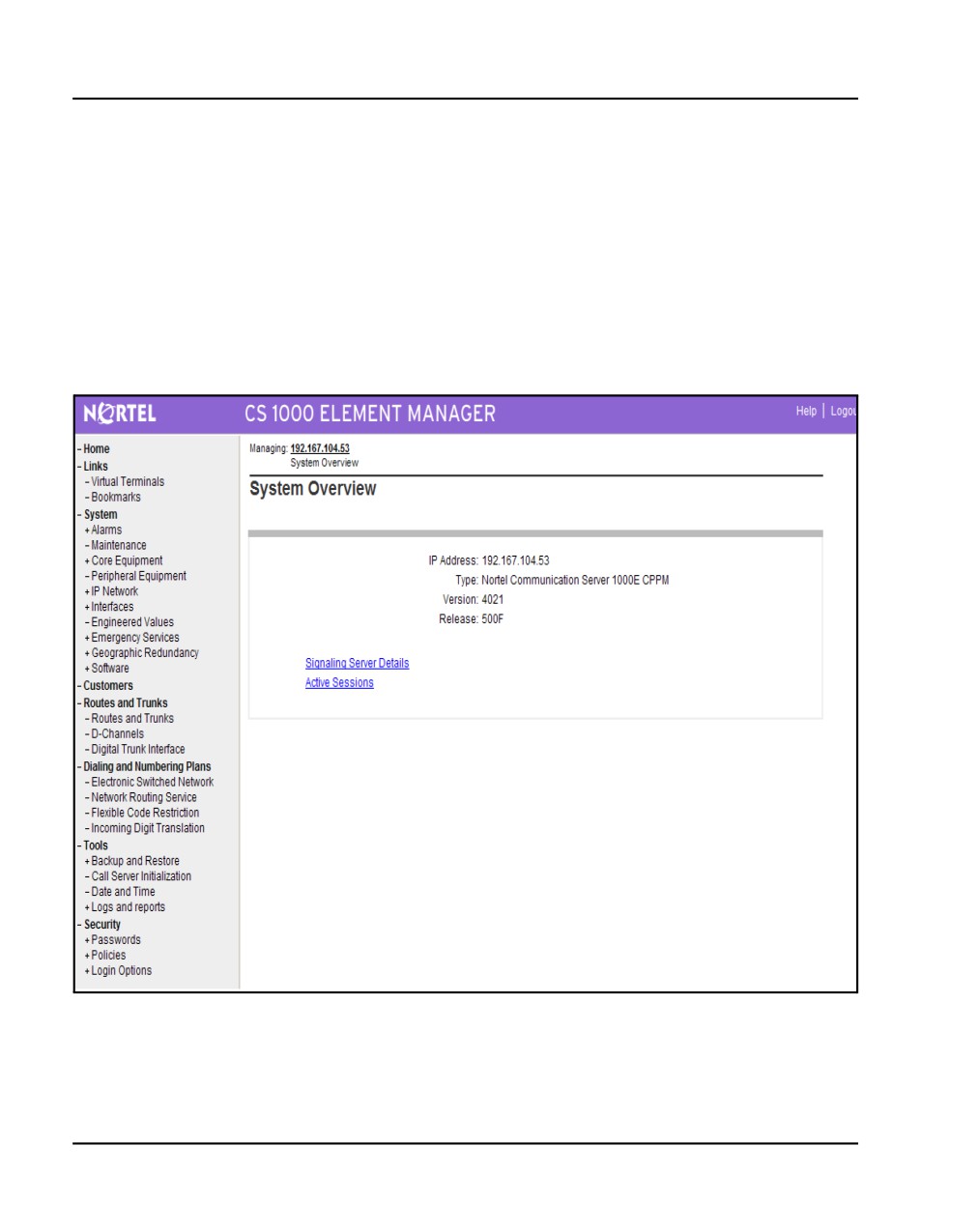
Figure 54 displays the Element Manager System Information home page.
Figure 54
Element Manager - System Information
NN43041-310
Standard 01.11
October 2008
Configuring the CS 1000E CP PM Call Server Page 169 of 466
1
Select System > IP Network > Nodes: Servers, Media Cards from the
navigator.
The Node Configuration web page appears. No nodes are defined.
2
Import the Node files from the leader Signaling Server.
a. Click Import Node Files on the Node Configuration web page.
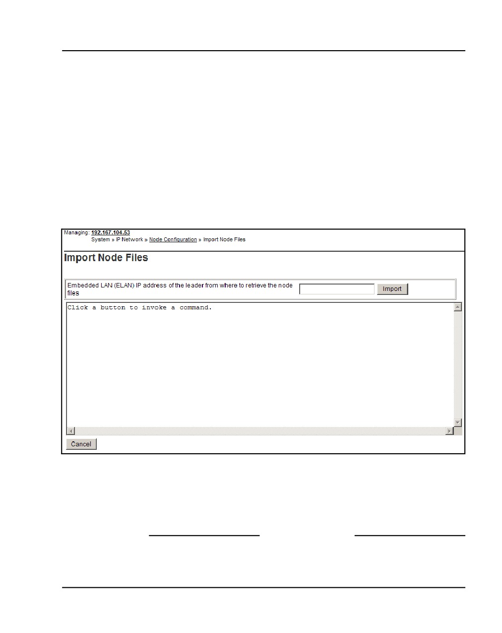
The Import Node Files screen in Figure 55 on page 169 appears.
b. Enter the ELAN IP address of the leader Signaling Server in the input
box.
Figure 55
Import Node Files - Retrieve and upgrade configuration files
3
Click Import.
A success message appears.
4
Click OK to go to the next procedure.
End of Procedure
Communication Server 1000E Installation and Commissioning
Page 170 of 466
Configuring the CS 1000E CP PM Call Server
Reviewing and submitting IP telephony node
configuration files
To review and submit IP telephony node configuration files, please refer to
IP Line: Description, Installation, and Operation (NN43100-500).
Adding a Follower Signaling Server to an
IP telephony node
To add a follower signaling server to an IP telephony node, follow the
procedure as given in Signaling Server: Installation and Commissioning
(NN43001-312).
Performing a datadump
Follow Procedure 37 to perform a datadump using Element Manager. This
procedure is an alternative to using the CLI to perform a datadump. The
datadump backs up new IP Telephony node files on the CS 1000E at the same
time that it backs up the customer database.
Procedure 37
Performing a datadump using Element Manager
From Element Manager (see Figure 53 on page 167 for details on logging in),
do the following:
1
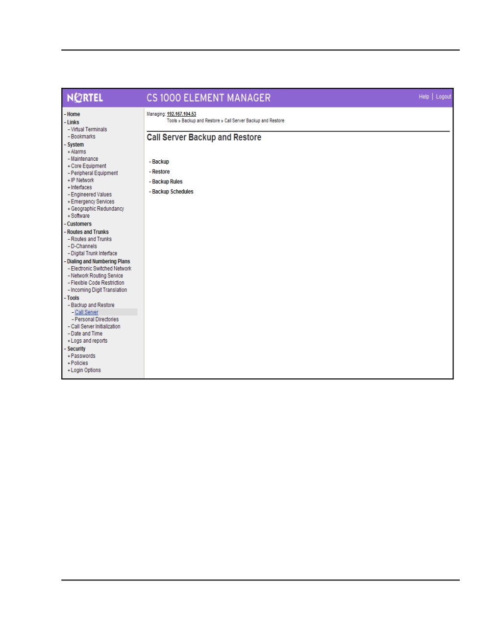
Choose Tools> Backup and Restore > Call Server from the navigator.
The Call Server Backup and Restore web page opens (see Figure 56
on page 171).
NN43041-310
Standard 01.11
October 2008
Configuring the CS 1000E CP PM Call Server Page 171 of 466
Figure 56
Call Server Backup and Restore web page
2
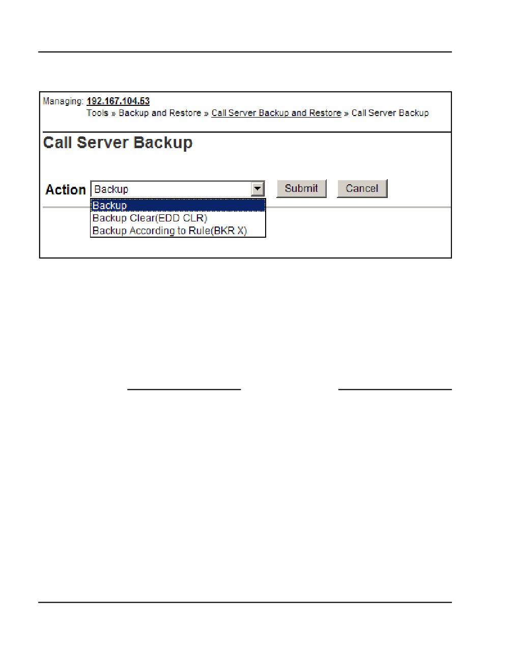
Select Backup.
The Call Server Backup web page appears (see Figure 57 on
page 172).
Communication Server 1000E Installation and Commissioning
Page 172 of 466
Configuring the CS 1000E CP PM Call Server
Figure 57
CS 1000E Backup
3
Select Backup from the Action drop-down list box.
4
Click Submit.
The message displays indicating “Backup in progress. Please wait...”
5
Click OK in the EDD complete dialog box.
The Backup function then displays information in a tabular form, indicating
the actions that were performed.
End of Procedure
NN43041-310
Standard 01.11
October 2008
238
Page 173 of 466
Installing a Signaling Server
Contents
This section contains information on the following topics:
Introduction
174
Readiness checklist
175
Installing the CP PM Signaling Server hardware
177
Connections
179
Installing the Signaling Server software
189
First boot of a new Nortel CP PM Signaling Server
216
Unpacking Help files for Virtual Terminal Emulator
235
Logging in to the Signaling Server
235
Verifying a successful configuration
237
Testing the Leader Signaling Server
237
Communication Server 1000E Installation and Commissioning
Page 174 of 466
Installing a Signaling Server
Introduction
This chapter contains general instructions to install a Nortel CP PM server
and detailed instructions to install a legacy Nortel ISP1100 server. This
chapter contains no instructions to install an IBM X306m or HP DL320-G4
COTS 1U server. Please see the IBM xSeries 306m Types 8848 and 8491
User Guide or the HP ProLiant DL320 Generation 4 Server User Guide
shipped with the COTS servers for detailed installation instructions. Of
particular note, the IBM X306m and HP DL320-G4 servers require four-post
NN43041-310
Standard 01.11
October 2008
Installing a Signaling Server
Page 175 of 466
rack mounting, as opposed to two-post rack mounting for the Nortel ISP1100
server.
IMPORTANT!
Instructions to install an IBM X306m or HP DL320-G4 COTS 1U server
are not included in this chapter. Detailed installation instructions can be
found in the IBM xSeries 306m Types 8848 and 8491 User Guide or the
HP ProLiant DL320 Generation 4 Server User Guide shipped with the
server.
Readiness checklist
Before installing a Signaling Server in a CS 1000 system, complete the
following checklist.
WARNING
Do not modify or use a supplied AC-power
cord if it is not the exact type required in the
region where the Signaling Server is installed
and used. Be sure to replace the cord with
the correct type.
Communication Server 1000E Installation and Commissioning
Page 176 of 466
Installing a Signaling Server
Table 14
Readiness checklist (Part 1 of 2)
Have you:
Read all safety instructions in Communication Server 1000E: Installation and
Commissioning (NN43041-310) or Communication Server 1000M and Meridian 1 Large
System Installation and Configuration (NN43021-310), as appropriate for your CS 1000
system?
Received all equipment and peripherals?
For a Nortel ISP1100 (NTDU27AA), IBM X306m (NTDU99AAE5), and HP DL320-G4
(NTDU97AA) Signaling Servers:
• installation accessories for rack-mounting the server
• AC-power cord
• a DTE-DTE null modem cable (supplied)
For a CS 1000E Nortel CP PM Signaling Server (NTDW61BAE5):
• NTDW6102E5 - CP PM Signaling Server Hard Drive kit
• N0118766 - CP PM Signaling Server Hard Drive Installation instructions
• NTAK19ECE6 - CP PM Signaling Server 2 port SDI Cable assembly kit
• NTDU0606E6 - CP PM Signaling Server 25cm RJ45 Ethernet Cable kit
• a DTE-DTE null modem cable (supplied)
• for a CS 1000M Nortel CP PM Signaling Server (NTDW66AAE5 model)
• NTDW6102E5 - CP PM Signaling Server Hard Drive kit
• N0118766 - CP PM Signaling Server Hard Drive Installation instructions
• NTAK19ECE6 - CP PM Signaling Server 2 port SDI Cable assembly kit
• NTDW69AAE5 - CP PM Signaling Server Large System Cabling kit
• N0106745 - CP PM Signaling Large System Cabling
• a DTE-DTE null modem cable (supplied)
Note: Save the packaging container and packing materials in case you must ship the
product.
NN43041-310
Standard 01.11
October 2008
Installing a Signaling Server
Page 177 of 466
Table 14
Readiness checklist (Part 2 of 2)
Have you:
Made sure the area meets all environmental requirements?
Checked for all power requirements?
Checked for correct grounding facilities?
Obtained the following:
• screwdrivers
• an ECOS 1023 POW-R-MATE or similar type of multimeter
• appropriate cable terminating tools
• a computer (maintenance terminal) to connect directly to the Signaling Server, with:
— teletype terminal (ANSI-W emulation, serial port, 9600 bps)
— a web browser for Element Manager (configure cache settings to check for new
web pages
— every time the browser is invoked, and to empty the cache when the browser is
closed)
Prepared the network data as suggested in Converging the Data Network with VoIP
(NN43001-260), Communication Server 1000E: Planning and Engineering
(NN43041-220) or Communication Server 1000M and Meridian 1 Large System
Planning and Engineering (NN43021-220), as appropriate for your CS 1000 system?
Read all safety instructions in Communication Server 1000E: Installation and
Commissioning (NN43041-310) or Communication Server 1000M and Meridian 1 Large
System Installation and Configuration (NN43021-310), as appropriate for your CS 1000
system?
Installing the CP PM Signaling Server hardware
The Nortel CP PM server is a circuit card, and thus is not mounted in a rack.
This section contains instructions for installing a Nortel CP PM Signaling
Server in a CS 1000E and a CS 1000M system.
Communication Server 1000E Installation and Commissioning
Page 178 of 466
Installing a Signaling Server
This section contains general instructions for installing the CP PM Signaling
Server circuit cards in CS 1000E and CS 1000M systems. For more detailed
installation instructions, refer to Circuit Card: Description and Installation
(NN43001-311) and Signaling Server: Installation and Commissioning
(NN43001-312).
IMPORTANT!
There are several switches on CP PM circuit cards. All switch settings
must be factory defaults except for the switch labelled “S5”. Switch S5
must be set to position 2 to support the internal hard drive used on the
CP PM Signaling Server circuit cards only.
Installation in a CS 1000E system
The NTDW61BAE5 model of the Nortel CP PM server is designed for use in
a CS 1000E system. The first task that must be performed is to install the hard
drive shipped with the server. For instructions, see "Install the hard drive on
a Nortel CP PM Signaling Server" in Signaling Server: Installation and
Commissioning (NN43001-312).
You can insert the NTDW61BAE5 model of the Nortel CP PM server into
any slot of a CS 1000E Media Gateway (MG 1000E or MG 1000B) or a
Media Gateway Controller (MGC) card. Keying prevents the
NTDW61BAE5 model from being inserted into this slot.
CAUTION — Equipment Damage
Do not insert the NTDW61BAE5 model of the
Nortel CP PM server into any slot of a CS
1000M Universal Equipment Module (UEM).
Doing so can cause electrical shorts on
adjacent circuit cards.
NN43041-310
Standard 01.11
October 2008
Installing a Signaling Server
Page 179 of 466
Connections
Connection checklist
WARNING
Do not modify or use a supplied AC power cord if it is not
the correct type required for the host region.
IMPORTANT!
Nortel CP PM servers are powered through the backplane of the Media
Gateway, Universal Equipment Module or 11C cabinet into which they
are installed and thus require no power cord.
Before connecting a Signaling Server, ensure that you have the following
materials on-hand.
Table 15
Connections checklist
Have you:
Obtained a serial cable (DTE-DTE null modem cable) to connect the server to a
maintenance terminal?
Obtained the NTAK19EC cable (if you are connecting a Nortel CP PM server)? This
cable adapts the 50-pin MDF connector on the back of the shelf of the Media Gateway,
Universal Equipment Module, or 11C cabinet to a 25-pin DB connector.
Obtained the CAT5 cables (or better) to connect the server to the ELAN and TLAN
subnets?
Connecting a Nortel CP PM Signaling Server
This section contains instructions for connecting the NTDW61BAE5 CP PM
Signaling Server to the ELAN and TLAN subnets of a CS 1000E and
Communication Server 1000E Installation and Commissioning
Page 180 of 466
Installing a Signaling Server
CS 1000M system respectively. It also contains instructions for connecting a
maintenance terminal to the Nortel CP PM Signaling Server.
The NTDW61BAE5 model of the Nortel CP PM Signaling Server was
designed for use in a CS 1000E system. As such, it is inserted into a slot of
the Media Gateway (MG 1000E or MG 1000B). The Media Gateway also
hosts the Media Gateway Controller (MGC) that has Ethernet ports for
connecting to the ELAN and TLAN subnets of your CS 1000 system.
However, it is common in a CS 1000E system for the Call Server to be
connected to the MGC through these ELAN and TLAN Ethernet ports. If the
Call Server is not connected to the MGC through these Ethernet ports, the
NTDW61BAE5 model of the CP PM Signaling Server uses them to connect
to the ELAN and TLAN subnets of the CS 1000E system. If the Call Server
is using the MGC ELAN and TLAN Ethernet ports, the Nortel CP PM
Signaling Server is connected directly to the ELAN and TLAN Ethernet
switches from the faceplate ELAN and TLAN Ethernet ports.
The NTDW66AAE5 model of the Nortel CP PM Signaling Server was
designed for use in a CS 1000M system.
Figure 58 shows the faceplates of the two models of the Nortel CP PM
Signaling Server with labeling for all components (NTDW61BAE5 on the
left and NTDW66AAE5 on the right).
NN43041-310
Standard 01.11
October 2008
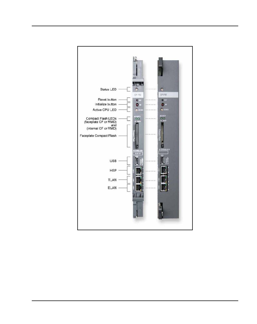
Installing a Signaling Server
Page 181 of 466
Figure 58
Faceplates of the Nortel CP PM server
Communication Server 1000E Installation and Commissioning
Page 182 of 466
Installing a Signaling Server
Procedure 38
Connecting a Nortel CP PM Signaling Server
Note: Refer to Figure 58 when performing the following procedure.
1
Establish a maintenance terminal connection at the back of the shelf of
the IPMG. The com (SDI) port of the CP PM circuit card Signaling Server
is routed through the backplane of the shelf to the 50 pin MDF connector
on the back of the shelf. A special cable is shipped with the CP PM
signaling server that adapts the 50 pin MDF connector to a 25 pin DB
connector (NTAK19EC). A DTE-DTE null modem serial cable is required
to adapt the SDI port to a typical PC serial port.
a. Connect the NTAK19EC cable (shipped with the CP PM Signaling
Server) to the 50 pin MDF connector on the back of the desired shelf
of the IPMG.
b. Connect a DTE-DTE null modem serial cable to the 25 pin DB
connector at the end of the NTAK19EC cable. Connect the other end
of the DTE-DTE null modem serial cable to the serial port on the
maintenance terminal.
2
Insert the Signaling Server circuit card into an appropriate slot on the shelf
of the IPMG. The CP PM Signaling Server is hot-pluggable so it may be
inserted without powering off the system. The maintenance terminal now
has access to the CP PM Signaling Server through the 50-pin MDF
connector associated with the card slot that the CP PM Signaling Server
is inserted into on the IPMG.
3
Connect the Signaling Server to the TLAN subnet. Insert the RJ-45 CAT5
(or better) cable into the TLAN port (TLAN network interface) on the front
of the Signaling Server. The TLAN port is the middle one of the three
network interfaces.
4
Connect the Signaling Server to the ELAN subnet. Insert the RJ-45 CAT5
(or better) cable into the ELAN port (ELAN network interface) on the front
of the Signaling Server. The ELAN port is the bottom one of the three
network interfaces.
NN43041-310
Standard 01.11
October 2008
Installing a Signaling Server
Page 183 of 466
5
Set the COM port on the maintenance terminal as follows:
•
Terminal type: VT100
•
Speed: 9 600
•
Data bits: 8
•
Parity: none
•
Stop bits: 1
•
Flow control: none
Note: The CP PM Signaling Server is shipped with the Admin Serial port
set to 9600 Bit/s. Other available speeds are 19 200, 38 400, and 115 200
Bits. You can change the port speed using the maintenance terminal. To
verify or change the baud rate on a Nortel CP PM Signaling Server, see
Signaling Server: Installation and Commissioning (NN43001-312).
6
Configure the Signaling Server maintenance terminal. Refer to Signaling
Server: Installation and Commissioning (NN43001-312).
End of Procedure
Complete Procedure 39 to connect a Nortel CP PM Signaling Server (model
NTDW61BAE5) to the ELAN and TLAN subnets of a CS 1000E system.
Procedure 39
Connecting a CP PM Signaling Server to the ELAN and TLAN subnets of
a CS 1000E system
1
Connect the Signaling Server to the ELAN subnet.
•
if the Call Server is not connected to the Media Gateway Controller
(MGC) CE port
— Insert the end of one of the 25-cm RJ-45 CAT5 Ethernet cables
shipped with the server (NTDU0606E6) into the ELAN network
interface port (ELAN port) on the faceplate of the server
— insert the other end of the 25-cm RJ-45 CAT5 Ethernet cable
into the MGC ELAN Ethernet port
•
if the Call Server is connected to the CE port
Communication Server 1000E Installation and Commissioning
Page 184 of 466
Installing a Signaling Server
— Insert the end of a longer RJ-45 CAT5 Ethernet cable (not
supplied) into the ELAN network interface port (ELAN port) on
the faceplate of the server
— Insert the other end of the RJ-45 CAT5 Ethernet cable into an
Ethernet port on the ELAN Ethernet switch
2
Connect the Signaling Server to the TLAN subnet.
•
if the Call Server is not connected to the Media Gateway Controller
(MGC)
— Insert the end of one of the 25-cm RJ-45 CAT5 Ethernet cables
shipped with the server (NTDU0606E6) into the TLAN network
interface port (TLAN port) on the faceplate of the server
— Insert the other end of the 25-cm RJ-45 CAT5 Ethernet cable
into the MGC TLAN Ethernet port
•
if the Call Server is connected to the MGC
— Insert the end of a longer RJ-45 CAT5 Ethernet cable (not
supplied) into the TLAN network interface port (TLAN port) on
the faceplate of the server
— Insert the other end of the RJ-45 CAT5 Ethernet cable into an
Ethernet port on the TLAN Ethernet switch
End of Procedure
Note: If the Call Server is connected to the Media Gateway Controller,
you can not use the 25-cm CAT5 Ethernet cables shipped with the
Signaling Server (NTDU0606E6). You must obtain CAT5 Ethernet
cables that are long enough to connect the Signaling Server directly to the
ELAN and TLAN Ethernet switches from the faceplate ELAN and
TLAN Ethernet ports.
Complete Procedure 40 to connect a Nortel CP PM Signaling Server (model
NTDW66AAE5) to the ELAN and TLAN subnets of a CS 1000M system.
IMPORTANT!
Connecting a Nortel CP PM Signaling Server to the ELAN and TLAN
subnets of a CS 1000M system causes a service disruption.
NN43041-310
Standard 01.11
October 2008
Installing a Signaling Server
Page 185 of 466
Procedure 40
Connecting a CP PM Signaling Server to the ELAN and TLAN subnets of
a CS 1000M system
1
Insert the end of an RJ-45 CAT5 Ethernet cable (not supplied) into the
ELAN network interface port (ELAN port) on the back of the CS 1000M
UEM. (You installed this ELAN port at the back of the UEM when you
installed the Signaling Server in the UEM.)
2
Insert the other end of the RJ-45 CAT5 Ethernet cable into an Ethernet
port on the ELAN Ethernet switch.
3
Insert the end of another RJ-45 CAT5 Ethernet cable (not supplied) into
the TLAN network interface port (TLAN port) on the back of the CS 1000M
UEM. (You installed this TLAN port at the back of the UEM when you
installed the Signaling Server in the UEM).
4
Insert the other end of the RJ-45 CAT5 Ethernet cable into an Ethernet
port on the TLAN Ethernet switch.
End of Procedure
Verify or change the baud rate
To verify or change the baud rate on a Nortel CP PM Signaling Server, see
Signaling Server: Installation and Commissioning (NN43001-312).
Connecting an IBM X306m Signaling Server
In geographic regions that are susceptible to electrical storms, Nortel
recommends that you plug the IBM X306m Signaling Server into an AC
surge suppressor.
Figure 59 shows the rear view of the IBM X306m Signaling Server.
Communication Server 1000E Installation and Commissioning
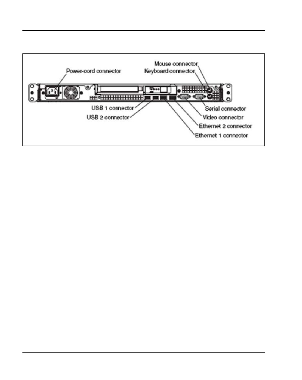
Page 186 of 466
Installing a Signaling Server
Figure 59
IBM X306m Signaling Server (rear view)
Note: Refer to Figure 59 when performing the following procedure.
Procedure 41
Connecting an IBM X306m Signaling Server
1
Connect the Signaling Server to the TLAN subnet. Insert the RJ-45 CAT5
(or better) cable into Port 1 (TLAN network interface) on the back of the
Signaling Server. Port 1 is the right-most of the two network interfaces.
2
Connect the Signaling Server to the ELAN subnet. Insert the RJ-45 CAT5
(or better) cable into PEthernet 2 connector (ELAN network interface) on
the back of the Signaling Server. Port 2 is the left-most of the two network
interfaces.
3
Connect a DTE-DTE null modem serial cable from the serial port on the
back of the Signaling Server to the serial port on a maintenance terminal.
4
Connect the Signaling Server power cord.
a. Check that the power cord is the type required in the region where
the Signaling Server is used. Do not modify or use the supplied AC
power cord if it is not the correct type.
b. Attach the female end of the power cord to the mating AC power
receptacle on the left side of the Signaling Server’s back panel. Plug
the male end of the AC power cord into the AC power source (wall
outlet).
NN43041-310
Standard 01.11
October 2008
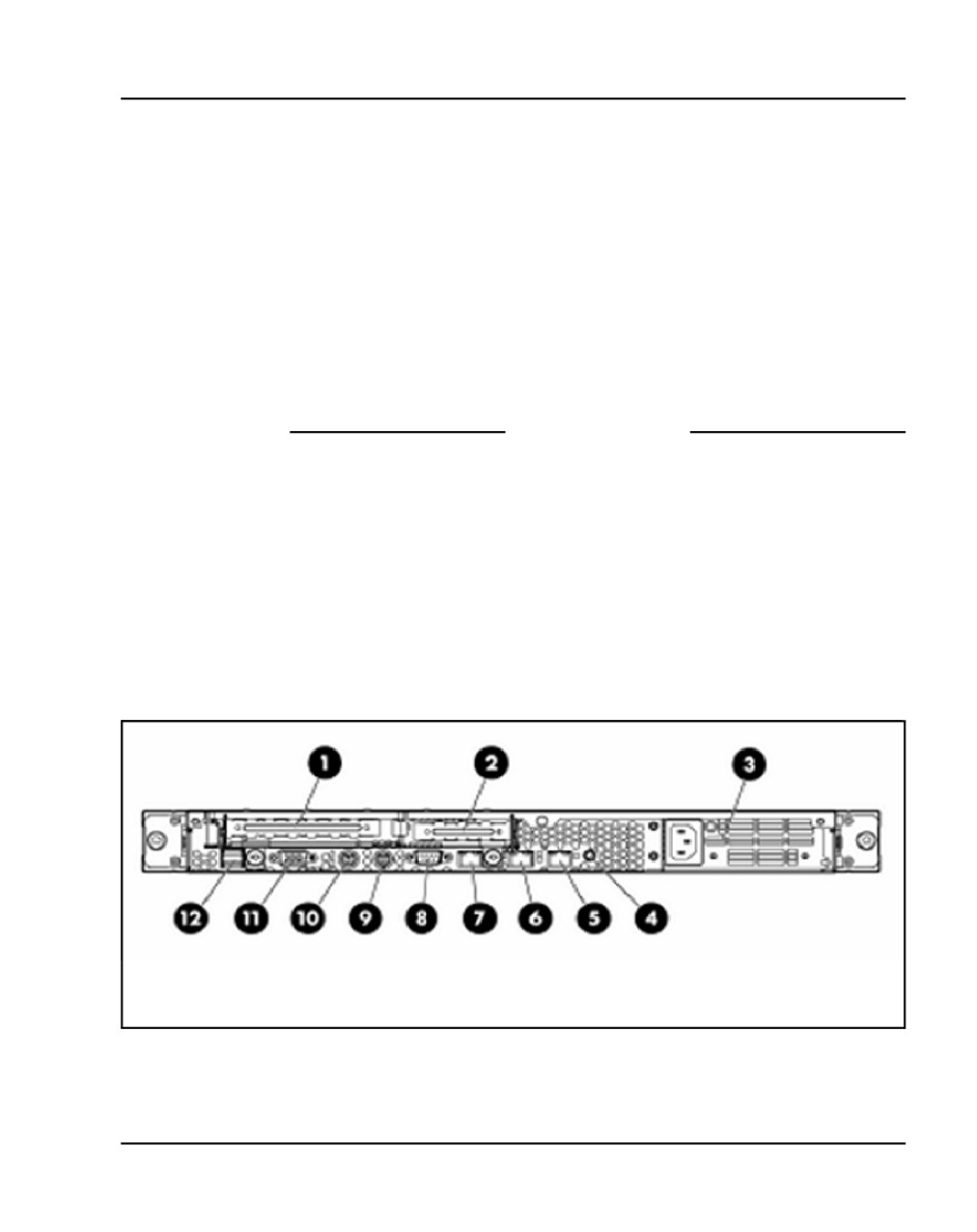
Installing a Signaling Server
Page 187 of 466
5
Set the baud rate for the serial port on the Signaling Server to 9 600 b/ps.
See Signaling Server: Installation and Commissioning (NN43001-312).
Note: The IBM X306m Signaling Server ships with the serial port set to
9600 b/ps.
6
Configure the connected maintenance terminal. See Signaling Server:
Installation and Commissioning (NN43001-312).
7
Press the Power switch.
Note: Refer to the Signaling Server Product Guide on the CD-ROM
shipped with the IBM X306m Signaling Server for additional operating
information.
End of Procedure
Connecting an HP DL320-G4 Signaling Server
In geographic regions that are susceptible to electrical storms, Nortel
recommends that you plug the HP DL320-G4 Signaling Server into an AC
surge suppressor.
Figure 60 shows the rear view of the HP DL320-G4 Signaling Server.
Figure 60
HP DL320-G4 Signaling Server (rear view)
Communication Server 1000E Installation and Commissioning
Page 188 of 466
Installing a Signaling Server
Procedure 42
Connecting an HP DL320-G4 Signaling Server
1
Connect the Signaling Server to the TLAN subnet. Insert the RJ-45 CAT5
(or better) cable labeled with the number 5 into the port (TLAN network
interface) on the back of the Signaling Server.
2
Connect the Signaling Server to the ELAN subnet. Insert the RJ-45 CAT5
(or better) cable labeled with the number 6 into the port (ELAN network
interface) on the back of the Signaling Server.
3
Connect a DTE-DTE null modem serial cable from the Serial Port on the
back of the Signaling Server to a maintenance terminal.
4
Connect the Signaling Server power cord.
a. Check that the power cord is the type required in the region where
the Signaling Server is used. Do not modify or use the supplied AC
power cord if it is not the correct type.
b. Attach the female end of the power cord to the mating AC power
receptacle on the right-hand side of the Signaling Server’s back
panel. Plug the male end of the AC power cord into the AC power
source (wall outlet).
5
Configure the COM1 serial port as the communication port for the
connected maintenance terminal. Set the COM 1 baud rate for the serial
port on the Signaling Server to 9 600 b/ps. See Signaling Server:
Installation and Commissioning (NN43001-312).
6
Configure the connected maintenance terminal. See Signaling Server:
Installation and Commissioning (NN43001-312).
7
Press the Power switch.
End of Procedure
Maintenance terminal configuration parameters
To configure Signaling Server maintenance terminal configuration
parameters, see the Maintenance chapter of Signaling Server: Installation
and Commissioning (NN43001-312).
NN43041-310
Standard 01.11
October 2008
Installing a Signaling Server
Page 189 of 466
Installing the Signaling Server software
IMPORTANT!
The Signaling Server is out-of-service during software upgrade.
Introduction
This section provides installation procedures for CS 1000 Release 5.0
Signaling Server software on an IBM X306m or HP DL320-G4 Signaling
Server.
IMPORTANT!
CP PM, IBM X306m and HP DL320-G4 Signaling Servers do not
support any Signaling Server software prior to CS 1000 Release 5.0.
IMPORTANT!
CS 1000 Release 5.0 Signaling Server software does not need to be
installed on the CP PM Signaling Server. It is delivered with the
Signaling Server software, operating system, applications and web files
pre-loaded onto the hard drive. Only basic system configuration
parameters need to be entered on the first boot of the CP PM Signaling
Server.
Before you begin
Before installing the software, you must do the following:
•
Connect and power up the Signaling Server. See “Connections” on
page 179.
•
For CP PM Signaling Servers, ensure that Switch S5 is set to position 2
(to support the internal hard disk drive)
•
For IBM X306m and HP DL320-G4 Signaling Servers, you must obtain
the CS 1000 Release 5.0 Signaling Server Software Install CD.
Communication Server 1000E Installation and Commissioning
Page 190 of 466
Installing a Signaling Server
Installing the software
To install software and enter basic system configuration parameters on an
IBM X306m or HP DL320-G4 Signaling Server, complete Procedure 43.
Procedure 43
Installing Signaling Server software
Upon completion of Step 1, this procedure takes approximately 45 minutes to
complete.
1
From your Planning and Engineering group, obtain the following network
and IP Telephony data for this Signaling Server:
•
node ID for the IP Telephony node
•
node IP address for the IP Telephony node
•
hostname for the Signaling Server
•
ELAN network interface IP address, Subnet mask, and Gateway
•
TLAN network interface IP address, Subnet mask, and Gateway
•
ELAN network interface IP address of the Call Server
•
Primary and Alternate NRS IP addresses for this networked system.
Refer toIP Peer Networking: Installation and Commissioning
(NN43001-313)
•
NRS role, if applicable. Refer to IP Peer Networking: Installation and
Commissioning (NN43001-313)
2
Boot the Signaling Server from the Removable Media Device (RMD):
•
For IBM X306m, HP DL320-G4, or Nortel ISP1100 Signaling
Servers, insert the CS 1000 Release 5.0 Signaling Server Software
CD into the CD drive and press the RST button on the front panel of
the Signaling Server to trigger a cold boot. This forces the Signaling
Server to boot from the CD.
•
For a Nortel CP PM Signaling Server, insert the CS 1000 Release 5.0
Signaling Server Software CF card into the faceplate CF drive and
press the RST button on the faceplate of the Signaling Server to
trigger a cold boot. The CP PM System BIOS Configuration screen
appears (see Figure 61) with an instruction to press F to force the
Signaling Server to boot from the CF card.
NN43041-310
Standard 01.11
October 2008
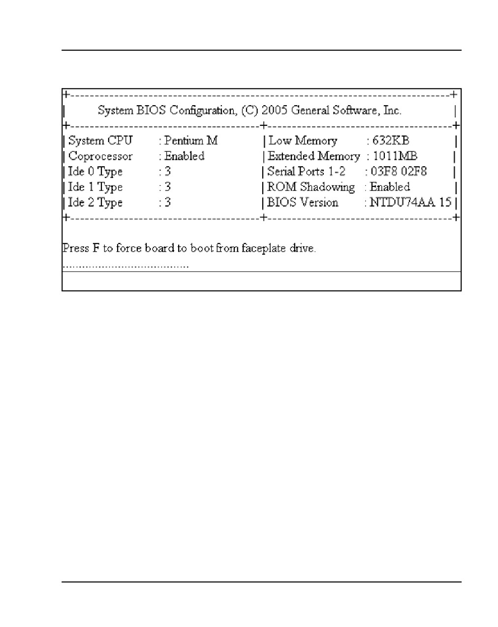
Installing a Signaling Server
Page 191 of 466
Figure 61
Nortel CP PM system BIOS configuration
•
The VxWorksTM banner screen appears (see Figure 62) followed by
system messages indicating that the Signaling Server Software
Installation Tool is being loaded from either the Signaling Server
Software CD or CF Card.
Communication Server 1000E Installation and Commissioning
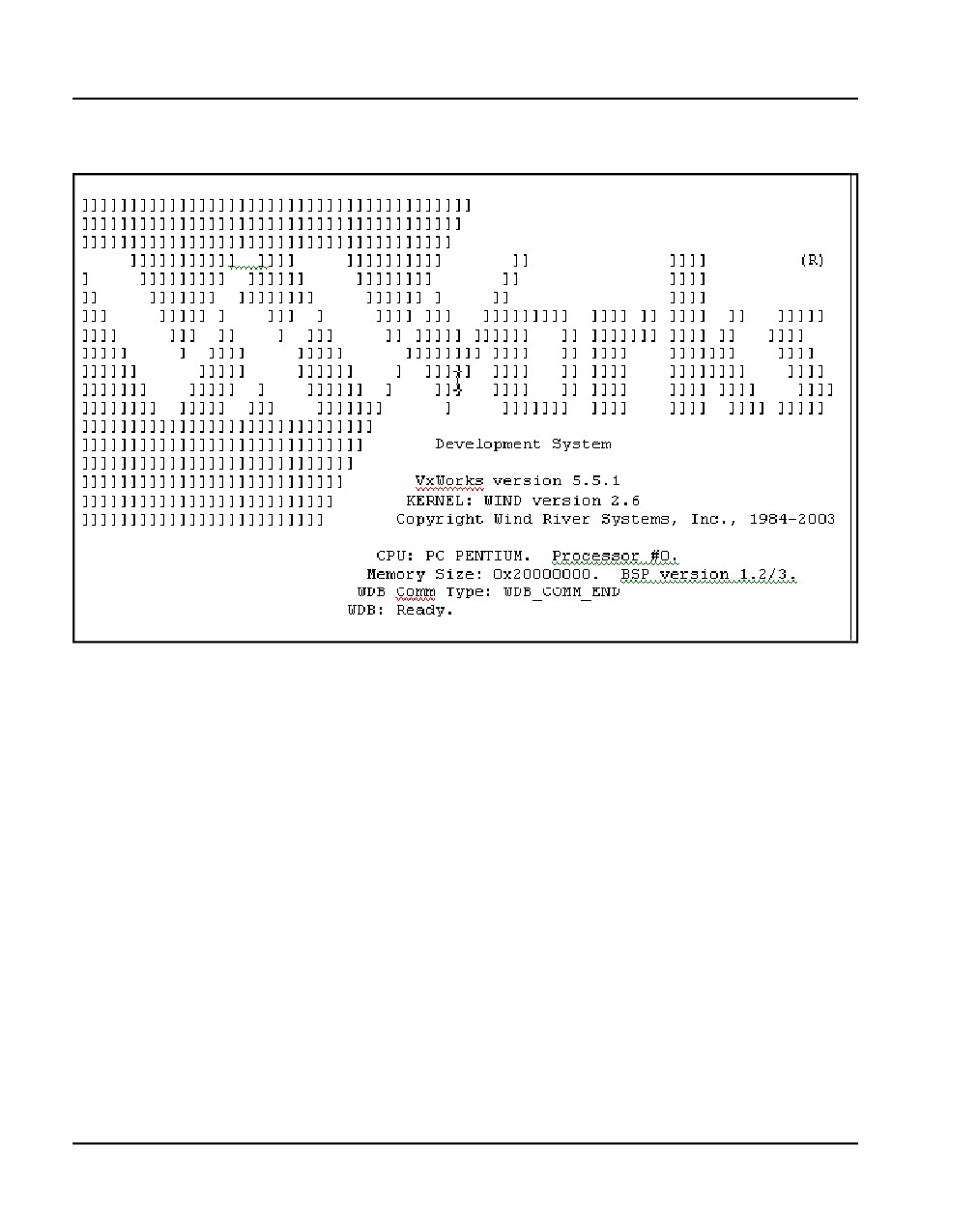
Page 192 of 466
Installing a Signaling Server
Figure 62
VxWorks system banner
When the Install Tool banner appears (Figure 63), press <CR> to perform
system checks and begin software installation.
NN43041-310
Standard 01.11
October 2008
Installing a Signaling Server
Page 193 of 466
Figure 63
Install Tool banner screen
CS 1000 Signaling Server Software Install Tool (sse-x.xx.xx)
=====================================================================
#####
#########
########
########`` `#############
########
``
`#############
#######`
######```####
#######
######``
`###
NORTEL NETWORKS
#######
#####``
####
####### #####`
#### Communication Server 1000 Software
`#########`
####`
#######`
#####
Copyright 2002 - 2006
`#######
#####’
##########
`###`
##``##########
#
##
`########################
`#
`########################
###########################``
`````````
````####````
Please press <CR> when ready ...
<CR>
3
Press <CR> to perform system checks. If the system has less than 1
Gbyte of RAM, the following error message appears:
WARNING: Your system has less than 1 GB RAM.
In order to run Rls 5.0 software you must
upgrade RAM to 1 GB and repeat install.
Otherwise serious service problems are likely
Please enter:
<CR> -> <q> - Quit.
<a> - Accept the possible risks and
continue install.
Press <CR> to quit. Upgrade to 1 Gbyte of RAM (see Signaling
Server: Installation and Commissioning (NN43001-312)) and restart
the Signaling Server Install Tool again.
Communication Server 1000E Installation and Commissioning
Page 194 of 466
Installing a Signaling Server
The system verifies the file systems.
•
If the hard drive of the Signaling Server is not partitioned, the file
systems verification process fails. Upon failure, the menu in
Figure 64 appears.
Figure 64
File systems verification failure
CS 1000 Signaling Server Software Install Tool (sse-x.xx.xx)
=====================================================================
The filesystems verification failed! (This is normal for a new
system.)
The hard disk must be (re)partitioned and (re)initialized. This will
erase all data on the hard disk. The system will then reboot and
the Install Tool will restart.
Please enter:
<CR> -> <a> - Partition and initialize the hard disk, then reboot.
Enter Choice> a
a. Enter a to partition and initialize the hard disk, and to reboot the
Signaling Server.
The system displays the messages:
Partitioning hard disk ...
Hard disk partitioning succeeded.
Creating filesystems ...
Filesystems creation succeeded.
Rebooting system ...
b. The Install Tool banner screen (Figure 63 on page 193)
reappears. Go back to beginning of Step 2. If the hard drive of
the Signaling Server is partitioned, the following system
messages appear.
Filesystems verification succeeded.
c. Confirm or enter the date and time (Figure 65 on page 195).
NN43041-310
Standard 01.11
October 2008
Installing a Signaling Server
Page 195 of 466
Figure 65
Date and time
CS 1000 Signaling Server Software Install Tool (sse-x.xx.xx)
====================================================================
You should ensure the system date and time are correct prior to
installation, since all files copied or created during install will
be time-stamped.
You can press <CR> to accept the current values.
Current date is: FRIDAY 01-04-2006
Enter new date (dd mm yyyy): 04 04 2006
Date is set to: MONDAY 04-04-2006
Current time is: 09:47:18
Enter new time (hh mm ss): 08 38 30
Time is set to: 08:38:30
Current date and time is:
MONDAY 04-04-2005, 08:38:30
•
When reinstalling the software on an existing system, the system
verifies the file systems. The disk check reports:
Filesystems verification succeeded.
The system summary appears (Figure 66 on page 196). Enter a to
continue the installation.
Note: For a new installation, the data fields in the system summary
are blank.
Communication Server 1000E Installation and Commissioning
Page 196 of 466
Installing a Signaling Server
Figure 66
System Summary
CS 1000 Signaling Server Software Install Tool (sse-x.xx.xx)
=====================================================================
------------------------------------------
SYSTEM INFORMATION
------------------------------------------
+================================================================+
| Hostname: SS_Node276_Ldr
S/W Ver: x.xx.xx
|
|
|
|
Role: Leader
Set TPS: Disabled
|
|
Node ID:
Vtrk TPS: Disabled
|
|
Node IP:
NRS Config: Alternate SIP
|
| H.323 ID: SS_Node276_Ldr
CS IP:
|
|
|
|
ELAN IP: 192.168.10.20
TLAN IP: 192.168.20.20
|
|
ELAN SM: 255.255.255.0
TLAN SM: 255.255.255.0
|
|
ELAN GW: 192.168.10.1
TLAN GW: 192.168.20.1
|
| ELAN MAC: 00:02:b3:c5:51:c6
TLAN MAC: 00:02:b3:c5:51:c7
|
+================================================================+
Please enter:
<CR> -> <a> - Continue with Install Tool.
<q> - Quit.
Enter Choice>
NN43041-310
Standard 01.11
October 2008
Installing a Signaling Server
Page 197 of 466
Figure 67
Install Tool Main Menu
CS 1000 Signaling Server Software Install Tool (sse-x.xx.xx)
=====================================================================
M A I N
M E N U
The Install Tool will install Signaling Server software and related
files. You will be prompted throughout the installation.
Please enter:
<CR> -> <a> - To perform a complete installation/upgrade (Signaling
Server s/w, IP Phone f/w, Voice Gateway Media
Card l/w, basic Signaling Server configuration).
<b> - To install/upgrade Signaling Server software only.
<c> - To copy IP Phone firmware only.
<d> - To copy Voice Gateway Media Card loadware only.
<e> - To perform basic Signaling Server configuration only.
<t> - To go to the Tools Menu.
<q> - Quit.
Enter Choice>
4
At the Main Menu (Figure 67), enter a to install Signaling Server software.
Option a performs options b, c, d, and e.
The following sample lines display on the screen:
Copying “/cd0/sse37012.p3/disk.sys” to “/u/disk.sys”.
Processing the install control file ...
“/cd0/sse37012.p3/install.dat” parsed.
Communication Server 1000E Installation and Commissioning
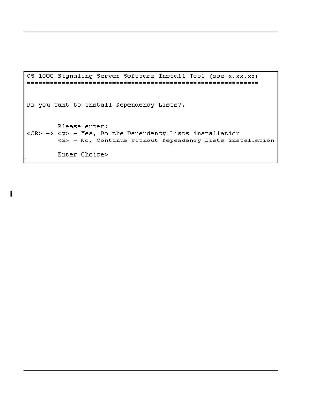
Page 198 of 466
Installing a Signaling Server
The Dependency Lists installation screen appears (Figure 68).
Figure 68
Dependency lists installation
5
Press <CR> or enter y to install the dependency lists. The Installation
Status Summary screen appears:
The Installation status screen appears (Figure 69 on page 199).
NN43041-310
Standard 01.11
October 2008
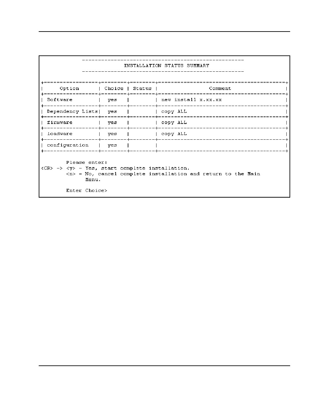
Installing a Signaling Server
Page 199 of 466
Figure 69
Installation Status
6
Enter y to start the installation. The screens shown in Figures 70 to 76,
which start on page 200, appear.
Communication Server 1000E Installation and Commissioning
Page 200 of 466
Installing a Signaling Server
Figure 70
Installation output
CS 1000 Signaling Server Software Install Tool (sse-x.xx.xx)
=====================================================================
You have selected to install version x.xx.xx on the system. As
this is a new install, all necessary directories and files will
be created on the hard disk.
Starting new install of version x.xx.xx.
Initializing protected partition ...
“/p” initialized.
Creating directory ... (many directories are created here) ...
Copying ... (many files are copied here) ...
Boot ROM “/p/load/bootrom.bin” installed.
Figure 71
Software installation success
CS 1000 Signaling Server Software Install Tool (sse-x.xx.xx)
=====================================================================
Software version x.xx.xx was installed successfully.
All files were copied to the hard disk.
NN43041-310
Standard 01.11
October 2008