F-14D. FLIGHT MANUAL (2004) - page 7
NAVAIR 01−F14AAD−1
7. Formation/altitude/airspeed
12. Egress
8. Communications
a. Target area considerations/frag
9. Radar plan
b. Rendezvous/RTF
10. Threat awareness (SAM, AAA, A/A)
13. Abort criteria/procedures
11. DECM/RWR/expendables
14. Safety.
ORIGINAL
6−4
NAVAIR 01−F14AAD−1
CHAPTER 7
Shore−Based Procedures
7.1
CHECKLISTS
have been properly corrected or deferred prior to accepting
the aircraft as ready for flight.
Aircraft checklists are available in two forms, based on
the degree of flightcrew familiarization; since the sequence
7.2.1
Area Around Aircraft
remains the same, the only difference in the forms is the
degree of amplification. As the flightcrew becomes more
En route to the aircraft, attention should be directed to
proficient in type, a more abbreviated form is available to
the maintenance effort going on in the line area. The flightĆ
promote operational efficiency, and safety is not comproĆ
crew should ensure that no hazardous situations exist. The
mised since, in all instances, the thoroughness of checks
entire area should also be generally examined for FOD
remains the same. The placarded takeoff and landing checkĆ
hazards.
lists on the forward cockpit instrument panel is a fundaĆ
The area around the aircraft that may not be visible
mentalăelement in all instances. In the interest of procedural
from the cockpit should be examined. Particular attention
standardization, the shore−based and carrier−based proceĆ
should be paid to support equipment adjacent to the aircraft.
dures are maintained the same, except for the response relaĆ
It should be determined that the wings and flight controls can
tive to the checks. The expanded procedures presented in
be safely moved and that the effect of jet blast during start and
thisăflight manual describe in detail those items that should
taxi will not create a dangerous situation.
be checked on each flight. Adherence to these procedures
will provide the flightcrew with a detailed status of weapons
7.2.2
Foreign Object Damage and
system performance incident to flight. However, it is incumĆ
Leak Inspection
bent on the flightcrew to expand the checks as necessary to
verify the corrective status of previously reported discrepĆ
Engine intakes and adjacent deck area are of prime
ancies. Reference should be made to the functional check
concern since the F110−GE−400 is highly susceptible to FOD
flight procedures
(Chapter 10, paragraph 10.2) for more
damage and the engines are capable of picking up objects
detailed tests that can be performed on the aircraft and
from the deck. AICS ramps, bleed doors, ECS cooling
weapons systems if deemed necessary. The flightcrew
intakes, exhausts, and afterburner ducts are catchalls for
shouldăbe thoroughly familiar with the details of the proceĆ
loose objects. They should be closely inspected for security
dures outlined herein so that the abbreviated checklist forms
and foreign objects. Inspect all panels for security and loose
of the procedures may be safely employed. As the first level
fasteners. While inspecting the aircraft for FOD, the flightĆ
of simplification, NAVAIR 01−F14AAD−1B (F−14D Pocket
crew should also be alert for any evidence of oil, hydraulic
Checklist), contains a reprint of the normal procedures, with
fluid, or fuel leaks.
less amplifying information.
7.2.3
Ground Safety Devices and Covers
7.1.1
Tactical Air Reconnaissance Pod System
The following items should be installed:
A [T] preceding the text of a procedural step identifies
items pertaining only to TARPS aircraft.
1. Main landing gear ground safety locks (two)
2. Nose landing gear ground safety pin
7.2
EXTERIOR INSPECTION
3. Tailhook safety pin (ashore)
A proper preflight inspection begins with a thorough
review of aircraft status and past maintenance history. An
4. Wheel chocks
understanding of previous discrepancies, corrective action
and their impact on the flight can best be gained at this time.
5. LAU−7/LAU−138/LAU−92 ground safety pins
The flightcrew should ensure that any and all discrepancies
6. Sidewinder seeker−head covers (if applicable).
7−1
ORIGINAL
NAVAIR 01−F14AAD−1
The following items should be removed:
7.2.7
Movable Surfaces
All movable surfaces (flight controls and high−lift
1. Intake, probe, bleed door, and ECS duct covers
devices) should be inspected for position, clearance, and
obvious damage.
2. Water−intrusion tape
3. Launch abort mechanism lock (if the aircraft is to be
7.2.8
Inspection Areas
towed)
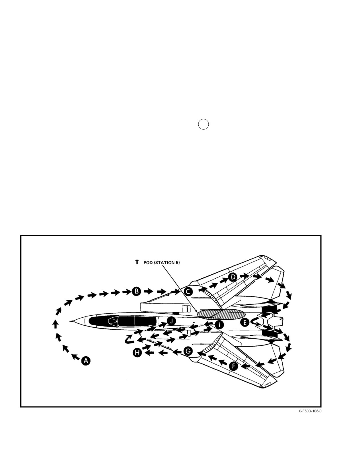
The following exterior inspection is divided into
10ăareas. (See Figure 7−1.) Checks peculiar to only one side
4. Tailhook safety pin (shipboard).
are designated (L) or (R) for the left or right side. Both the
pilot and RIO should preflight the entire aircraft individually.
7.2.4
Surface Condition
7.2.8.1
A Forward Fuselage
All surfaces should be checked for cracks, distortion,
or loose or missing fasteners. All lights and lenses should be
1. Access panel fasteners forward of engine inlets
checked for cracks and cleanliness.
No Loose or Missing Fasteners.
2. Gun Safety Pin Installed in Clearing Sector HoldĆ
7.2.5
Security of Panels
back Assembly, Louvers Clear, cannon plug conĆ
All fasteners should be flush and secure on all panels.
nected, wheelwell armament safety override switch
guard down.
7.2.6
Leaks
3. Probes Secure, Openings Clear, AOA Probe Free
All surfaces, lines, and actuators should be checked for
For Rotation.
oil, fuel, and hydraulic leaks. Particular attention should be
4. Nose wheelwell:
paid to the underside of the fuselage, engine nacelles, and
outer wing panels.
a. Electrical leads Ċ Connected, No Evidence of
Overheating.
Figure 7Ć1.ĄExterior Inspection
ORIGINAL
7−2
NAVAIR 01−F14AAD−1
b. Hydraulic lines No Chafing or Leaks.
7.2.8.2
B Right Inlet
c. Doors and linkages Cotter Pins Installed,
1.
Ramps, metal seals, and rubber seals Ċ Intact, Free
NoĂDistortion.
of Dirt, Grit, and Cracks.
d. Brake accumulators 1,900 Psi Minimum.
2.
IGV Ċ Blades and Stators Free of Nicks and
Cracks.
e. Canopy air bottle gauge Ċ 1,200 Psi Minimum.
Plane captain to verify that all visible damage has
f. Emergency landing gear nitrogen bottle gauge
been blended.
Ċ 3,000 Psi Minimum.
3.
ECS heat exchanger inlet and fan
g. Emergency landing gear air release valve Ċ
Ensure That Valve Is in Closed Position.
a. Fan Ċ Free Rotation.
h. Retract actuator Ċ Piston Clean, No Leaks.
b. Overspeed pin Ċ Recessed.
i. Flight maintenance indicator Ċ Secure.
c. ECS inlet Ċ Free of FOD, Cables Connected
(two).
j. Antiskid control box BIT flags Ċ Not Tripped.
4.
Inlet Ċ Free of Standing Water, Drains Clear.
k. Cabin pressure port screens Ċ Clean.
7.2.8.3
C Right Nacelle and Sponson
l. Master arm override Ċ Cover Closed.
1.
Station 7 and 8 stores
5.
Nose strut Ċ Piston Clean, Free of Cracks and
Scoring, and Uplock Roller Free.
a. Stores Ċ Aligned.
6.
Steering actuator Ċ Secure, No Leaks.
b. Access panels Ċ Secure.
7.
Launch bar and holdback fitting
c. Sidewinder missile launcher
a. Abort Ċ Full Up.
(1) LAU−7 Sidewinder coolant doors Ċ
b. Roller Ċ Free Rotation.
Latched.
c. Uplatch and holdback Ċ Free Movement.
(2) LAU−138 chaff loading and gas bottle safety
handle Ċ Stowed.
8.
Nosewheels and tires Ċ Inflation, No Cuts, Bulges,
Uneven Wear, or Imbedded Objects.
d. Stores safety pins Ċ Installed.
9.
Drag brace Ċ No Leaks, Door Secure.
If external tank/MXU − 611 aboard:
10. Approach lights Ċ Lenses Clean, No Cracks,
d. Ground safety handle Ċ Pulled.
Secure.
11. TV camera Ċ Check, Blue Desiccant.
e. Fuel quantity sight gauge Ċ Ball Float Vertical.
12. Dual chin pod Ċ IRST, TV Cameras (or simulaĆ
f. Sway braces Ċ Tightened Down.
tors), and Anticollision Light Secure.
g. Hook latched indicator Ċ White Vertical Line
13. Radome Ċ Lock Handle Fastened, Rosemont Probe
Visible.
Straight.
h. Inboard and outboard fuel caps Ċ Fastened With
14. OBOGS concentrator vent outlet Ċ No
Butterfly Latch Secured Facing Aft.
Obstructions.
7−3
ORIGINAL
NAVAIR 01−F14AAD−1
2.
Main wheelwell
Note
a. Doors and linkages Ċ Secure.
Engine must be running for an accurate reading.
b. Uplock microrollers Ċ Free.
13. Hook dashpot pressure gauge Ċ 800 ±10 Psi.
c. Uplock hooks Ċ Secure.
14. Ventral Ċ No Damage, IDG Oil Cooler Intake
d. Hydraulic lines Ċ No Chafing or Leaks.
Clear.
3.
Drag brace Ċ Secure, Downlock Safety Pin
Forward.
7.2.8.4
D Right Glove and Wing
4.
Side brace Ċ Seated in Latch.
1.
Slats, flaps, and cove doors Ċ Surfaces and Hinges
Secure.
5.
Main struts Ċ Pistons Clean, Free of Cracks or
Scoring.
2.
Wing cavity seal Ċ Free of Cuts and Chafing.
6.
Brakes Ċ Pucks Safety − Wired; Wear Indicators
3.
Formation and position lights Ċ Intact, Lenses
Visible
(pins at least flush). Lower Torque Arm
Clean.
Swivel; Key and Key Retainer Properly Installed
and Safety Wired.
7.2.8.5
E Aft and Under Fuselage
7.
Hubcap Ċ Secure, Safety−Wired.
1.
Horizontal tails Ċ Leading Edges Free of Damage.
8.
Main wheels and tires
2.
Exhaust nozzles and fairings:
a. Wheels and tires Ċ Inflation, Cuts, Bulges,
Uneven Wear, Imbedded Objects (look behind
a. Nozzles and fairings Ċ No Cracked or Missing
chocks)
Flaps or Seals.
b. Fairing cable Ċ Properly Tensioned (pull on
b. Uplock Hooks Ċ Secure.
cable, fairing flaps should not move).
9.
Gear down microrollers Ċ Contact Made.
c. Bottom surface Ċ No Scrapes or Cracks.
10. Engine compartment (if applicable)
d. Spray bars and flameholder Ċ Intact.
a. Integrated drive generator − transmission fluid Ċ
e. Turbine blades Ċ No Evidence of Overheating.
Fluid Visible, Filter Pins (two) Flush.
3.
Fuel vent Ċ No Leakage or FOD.
b. Engine oil servicing caps Ċ Check.
4.
Tailhook
c. Bilges Ċ No FOD, Evidence of Overheating, or
Leakage.
a. Hook point Ċ Smooth.
d. Fuel, oil, and hydraulic lines Ċ Free of chafing
b. Nut and cotter pin Ċ Installed.
or Leaks.
c. Safety pin Ċ Remove if Hook Is Securely
e. Bleed air lines Ċ No Heat Discoloration or
Latched Up.
Damage.
5.
Backup flight control module Ċ No Leaks (feel aft
f. AB fuel pump filter Ċ Pin Flush.
of inspection doors), Filter Pins Flush, Close Both
Access Doors.
g. Lube and scavenge bypass filter Ċ Pin Flush.
6.
Fuel dump Ċ No Leakage From Mast, Free of FOD.
h. Oil nozzle filter Ċ Pin Flush.
7.
Stations 3 through 6 stores
11. Flight hydraulic reservoir Ċ 1,800 Psi Minimum,
a. Stores Ċ Aligned.
Filter Pins Flush.
b. Access panels Ċ Secure.
12. Flight hydraulic system tape gauge Ċ Minimum of
c. Stores safety pins Ċ Installed.
Seven on Tape.
ORIGINAL
7−4
NAVAIR 01−F14AAD−1
8.
Fuel cavity drains Ċ No Leakage.
2.
Main wheelwell
9.
[T] Pod Ċ Check for Security.
a. Doors and linkages Ċ Secure.
10. [T] Protective window covers Ċ Removed.
b. Uplock microrollers Ċ Free.
11. [T] Camera windows Ċ Clean.
c. Uplock hooks Ċ Secure.
12. [T] Camera sensor control Ċ As Briefed.
d. Hydraulic lines Ċ No Chafing or Leaks.
13. [T] Light meter Ċ Facing Outboard.
3.
Drag brace Ċ Secure, Down Lock Safety Pin
Forward.
14. [T] Lens filter Ċ As Briefed.
4.
Side brace Ċ Seated in Latch.
7.2.8.6
F Left Glove and Wing
5.
Main struts Ċ Pistons Clean, Free of Cracks or
Scoring.
1.
Slats, flaps, and cove doors Ċ Surfaces and Hinges
Secure.
6.
Brakes Pucks Safety−Wired; Wear Indicators
Visible
(pins at least flush). Lower Torque Arm
2.
Wing cavity seal Ċ Free of Cuts and Chafing.
Swivel; Key and Key Retainer Properly Installed
and Safety−Wired.
3.
Formation and position lights Ċ Intact, Lenses
Clean.
7.
Hubcap Ċ Secure, Safety−Wired.
8.
Main wheels and tires
7.2.8.7
G Left Nacelle and Sponson
a. Wheels and tires Ċ Inflation, Cuts, Bulges,
1.
Station 1 and 2 racks and stores
Uneven Wear, Imbedded Objects (look behind
chocks).
a. Racks and stores Ċ Aligned.
b. Uplock hooks Ċ Secure.
b. Access panels Ċ Secure.
9.
Gear−up microrollers Ċ Contact Not Made.
c. Sidewinder missile launcher
10. Engine compartment (if applicable)
(1) LAU−7 Sidewinder coolant doors Ċ
Latched.
a. IDG Ċ Fluid Visible (two) Pins Flush.
(2) LAU−138 chaff loading and gas bottle safety
b. Engine oil servicing caps Ċ Check.
handles Ċ Stowed.
c. Bilges Ċ No FOD, Evidence of Overheating, or
d. Stores safety pins Ċ Installed.
Leakage.
If external tanks aboard:
d. Fuel, oil, and hydraulic lines Ċ Free of Chafing
or Leaks.
e. Ground safety handle Ċ Pulled.
e. Bleed air lines Ċ No Heat Discoloration or
f. Fuel quantity sight gauge Ċ Ball Float Vertical.
Damage.
g. Sway braces Ċ Tightened Down.
f. Afterburner fuel filter Ċ Pin Flush.
h. Hook latch indicator Ċ White Vertical Line
g. Lube and scavenge bypass filter Ċ Pin Flush.
Visible.
h. Oil nozzle filter Ċ Pin Flush.
i. Inboard and outboard fuel caps Ċ Fastened With
Butterfly Latch Secured Facing Aft.
7−5
ORIGINAL
NAVAIR 01−F14AAD−1
11. Combined hydraulic reservoir Ċ 1,800 Psi Mini−
6. Speedbrake Ċ No Distortion or Leaks.
mum, Filter Pins Flush.
7. Vertical tails and rudders Ċ No Distortion, Lights
12. Combined hydraulic system tape gauge Ċ MiniĆ
Intact.
mum of Seven on Tape.
7.2.8.10
J
Canopy
Note
Engine must be running for an accurate reading.
1. Canopy lanyard Ċ Connected, Yellow Flag
Attached at Both Ends.
13. Airstart door Ċ Ground Hydraulic and Electric
Covers Tight.
2. Auxiliary canopy bottle Ċ Cable Taut.
14. Ventral Ċ No Damage, IDG Oil Cooler Intake
3. Canopy hooks and seal Ċ Secure, Seal Intact.
Clear.
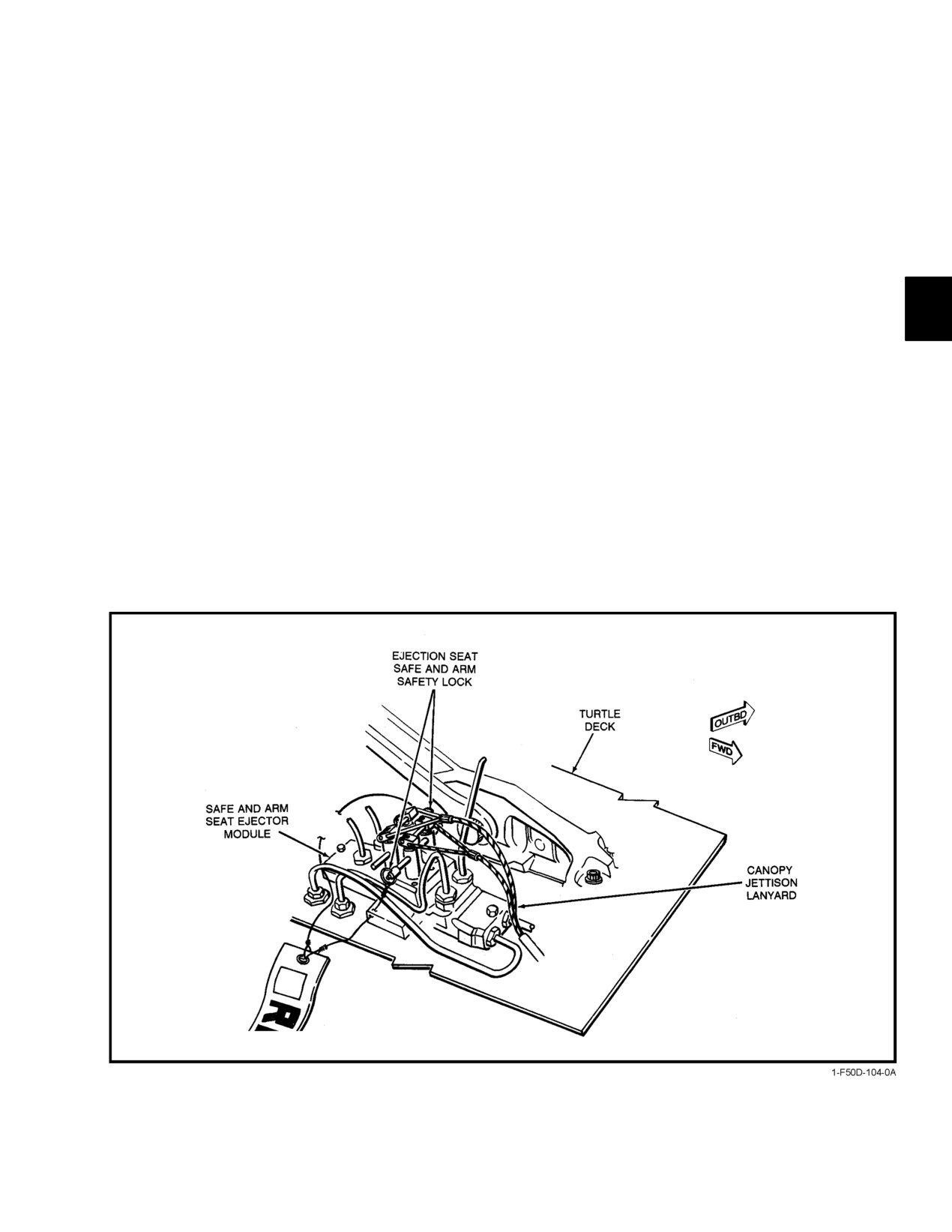
4. Ejection seat safe−and−arm device safety pins
(see Figure 7−2 ) Ċ Pulled.
7.2.8.8
H Left Inlet
5. Auxiliary canopy bottle gauge Ċ
800 psi
1.
Ramps, metal seals, and rubber seals Ċ Intact, Free
Minimum.
of Dirt, Grit, and Cracks.
6. Blade antennas Ċ Intact.
2.
IGV Ċ Blades and Stators IGV Free of Nicks and
Cracks.
7. Canopy Ċ Clean, Free of Cracks and Deep
Scratches.
Plane captain to verify that all visible damage has
been blended.
7.3
EJECTION SEAT INSPECTION
3.
Ice detector (L) Ċ Secure.
The pilot and RIO shall perform the following checks
on their respective ejection seats prior to flight. The ground
4.
ECS heat exchanger inlet and fan
safety pin in the seat firing handle is the only ground safety
device. It must be removed and stowed before flight. AbbreĆ
a. Fan Ċ Free Rotation.
viated preflight checklists for the ejection seat are provided
in the pocket checklist and on the ejection seat headbox.
b. Overspeed pin Ċ Recessed.
1. SAFE/ARMED handle Ċ SAFE.
c. Inlet Free of FOD, Cables Connected (two).
2. Manual override handle Ċ Full Down and Locked.
5.
Outboard spoiler module temperature indicator
and servicing Ċ No Leaks, Fluid Indicator Rod
3. Catapult manifold valve Ċ Secure, Hoses
Protruding.
Connected.
6.
Inlet Ċ Free of Standing Water, Drains Clear.
Check that retaining pin is installed.
4. Top latch mechanism Ċ Latched.
7.2.8.9
I
Fuselage Top Deck and Wings
Check that indicator plunger is flush with end of top
latch plunger.
1.
Bleed exit doors Ċ Free of FOD, Hardware Intact.
2.
ECS heat exchanger exhausts Ċ Free of FOD and
Cracks.
3.
Antennas Ċ Check.
If the top latch mechanism is not latched, the seat
4.
Overwing fairings Ċ No Cracked or Bent Fingers.
could rise up the catapult rails during aircraft
maneuvers.
5.
Eyebrow doors Ċ Intact.
ORIGINAL
7−6
NAVAIR 01−F14AAD−1
5.
Parachute withdrawal line Ċ Connected.
b. Emergency oxygen manual actuator Ċ ConĆ
nected and Stowed.
Check that parachute withdrawal line is correctly
secured to parachute deployment rocket stirrup.
c. Emergency oxygen and locator beacon lanyards
Ċ Connected to Deck.
6.
Left pitot head Ċ Stowed.
13. Oxygen/communications and anti−g lines Ċ ConĆ
7.
Thermal batteries Ċ Not Expended.
nected to Aircraft Connections.
Check that battery−expended indicator on electronic
14. Personnel services disconnect block Ċ Secured to
Seat Bucket, Lanyard Attached to Deck.
sequencer is not activated.
8.
Left trombone tubes Ċ Connected, Retaining Pin
15. Lapbelts Ċ Secure.
Installed.
Pull up on each lapbelt to ensure that lugs are secure
9.
Leg restraint lines Ċ Secured to Deck, Not Twisted,
in seat bucket locks.
End Fittings Secured in Seat Bucket Locks.
16. Right trombone tubes Ċ Connected, Retaining Pin
10. Seat firing initiators Ċ Firing Linkage Connected
Installed.
to Sears.
17. Right pitot head Ċ Stowed.
11. Pyrotechnic quick disconnects Ċ Connected, Red
Bands Not Visible.
18. Parachute container lid Ċ Secure, Sealed.
12. Survival kit Ċ Check.
Check environmental seal indicator for correct
indication.
a. Oxygen pressure gauge Ċ In the Black.
Figure 7Ć2.ĄEjection Seat Safe−and−Arm Module
7−7
ORIGINAL
NAVAIR 01−F14AAD−1
19. Parachute risers Ċ Properly Routed.
4. ICS panel
Check that risers are routed down forward face of
a. VOL knob Ċ As Desired.
parachute container and behind retention strap.
b. Amplifier Ċ NORM.
20. Ejection seat and canopy pins Ċ Stowed.
c. Function switch Ċ COLD MIC.
7.4
PILOT PROCEDURES
5. Radio VOLUME panel.
The interior inspection provides a systematic coverage
a. JTIDS SEL switch Ċ Set.
of all cockpit controls to ensure proper setup prior to the
b. VOLUME knobs Ċ As Desired.
application of external power, assuming no external air−conĆ
ditioning source will be used prior to engine start. These
6. TACAN mode switch Ċ OFF.
checks correspond to the condition that the plane captain
should set up in the cockpit as part of the preflight. Each
a. Channel Ċ Set.
cockpit setup consists of a sequential sweep of controls on the
left console, instrument panel, and right console.
b. VOL knob Ċ Counterclockwise.
7. STAB AUG switches Ċ OFF.
7.4.1
Interior Inspection Pilot
8. U/VHF Ċ OFF.
NATOPS prohibits the attaching or stowing of
unauthorized equipment on or above the canopy
The emergency wingsweep handle can be moved
independent of the wings and wingsweep indicaĆ
rails during CV launch and arrestment, due to the
tors when no hydraulic power and/or electrical
potential for missile hazard.
power are on the aircraft. Care must be taken to
1.
Harnessing Ċ Fasten.
accurately determine the position of the emerĆ
gency wingsweep handle prior to application of
a. Leg restraint lines and garters Ċ Connect.
hydraulic power. Inadvertent wingsweep to the
Ensure that leg lines are not twisted or looped.
position selected by the emergency wingsweep
handle may occur, resulting in potential damage
b. Lapbelt Ċ Connect and Adjust.
to the aircraft. When positioning the wings durĆ
Connect lapbelt straps and adjust snug so as to
ing ground operation other than pilot poststart or
provide secure lap restraint in flight and seat kit
postlanding checklist procedures, use the emerĆ
suspension for ground egress or ejection.
gency wingsweep handle to minimize the possiĆ
bility of moving the wings inadvertently.
c. Parachute release fittings Ċ Attach to Harness
Buckles.
9. Wing−sweep switch Ċ MAN.
d. Anti−g and oxygen/communication leads Ċ
10. Emergency wingsweep handle Ċ Corresponding.
Attach.
11. Left and right throttles Ċ OFF.
When connecting the oxygen/communication
fitting, avoid twisting the hard hose.
12. Exterior lights master switch Ċ Set.
e. Inertia reel Ċ Check.
Position switch in accordance with standard proceĆ
dures for day or night and field or carrier operations.
Position shoulder harness lock lever forward to
lock position. Check that both shoulder straps
13. FLAP handle Ċ CORRESPONDING.
lock evenly and securely. Move lever aft to
14. Throttle friction leverOFF (aft).
unlock harness.
15. ASYM LIMITER switch Ċ ON (guard down).
Attach composite fitting without causing unnecĆ
essary twisting of hard hose.
16. L and R ENG mode switches Ċ PRI.
17. BACK UP IGNITION switch Ċ OFF.
2.
OBOGS master switch Ċ OFF.
18. THROTTLE TEMP switch Ċ NORM.
3.
TONE VOLUME controls Ċ Set.
ORIGINAL
7−8
NAVAIR 01−F14AAD−1
19. THROTTLE MODE switch Ċ BOOST.
35. Circuit breakers Ċ Checked.
20. L and R INLET RAMPS switches Ċ AUTO.
36. HYD HAND PUMP Ċ Check.
21. ANTI SKID SPOILER BK switch Ċ OFF.
Extend handpump handle and stroke to check
firmness of pumping action and an indication of
22. FUEL panel
pressure buildup on the brake pressure gauge. Stow
handpump handle in a convenient position for ready
a. WING/EXT TRANS switch Ċ AUTO.
access.
b. REFUEL PROBE switch Ċ RET.
37. HOOK handle Ċ Corresponding.
c. DUMP switch Ċ OFF.
38. GUN ROUNDS panel Ċ Set.
d. FEED switch Ċ NORM (guard down).
39. DISPLAYS panel
23. LDG GEAR handle Ċ DN.
a. HUD MODE switch Ċ Set.
Check HYD ISOL switch in TO/LDG.
b. HUD DECLUTTER switch Ċ Set.
24. NOSE STRUT switch Ċ OFF.
c. HUD FORMAT switch Ċ Set.
25. Parking brake Ċ Pull.
d. HUD/VDI ALT switch Ċ BARO.
26. Altimeter Ċ Set.
e. HUD PWR switch Ċ OFF.
Set field or carrier elevation as applicable.
f. ECM switch Ċ Set.
27. Radar altimeter Ċ OFF.
g. TCS FOV switch Ċ Set.
28. Standby attitude gyro Ċ Caged.
40. ELEV LEAD knob Ċ Set.
29. Left and right FUEL SHUT OFF handles Ċ In.
41. SW COOL switch Ċ Set.
30. MA ARM switch Ċ OFF (guard down).
42. L and R generator switches Ċ NORM.
31. ACM switch Ċ OFF (guard down).
32. Multifunction display mode switches Ċ OFF.
Note
Ground engine operation without electrical powĆ
er supplied by either the generators or external
Visually check for security of cockpit equipment,
power may cause 20−mm ammunition detonation
particularly the multifunction displays, HUD,
because of excessive heat in the gun ammunition
and instrument panel gauges.
drum.
33. Clock Ċ Wind and Set.
43. EMERG generator switch Ċ NORM (guard down).
34. Fuel BINGO Ċ Set.
44. Air−condition controls
Set total fuel remaining value for initial activation
a. TEMP mode select switch Ċ AUTO.
of fuel BINGO caution reminder consistent with
mission profile to be flown.
b. TEMP thumbwheel control Ċ As Desired
(5 to 7 midrange).
7−9
ORIGINAL
NAVAIR 01−F14AAD−1
c. CABIN PRESS switch Ċ NORM.
d. AIR SOURCE Ċ OFF.
45. WSHLD AIR switch Ċ OFF.
Wings will move to emergency handle position
46. ANTI−ICE switch Ċ AUTO/OFF.
regardless of wing−sweep cb position.
47. ARA−63 panel
Note
a. CHANNEL selector Set.
b. POWER switch Ċ OFF.
If wings are in OV SW, do not extend handle.
48. MASTER LIGHT panel controls Ċ As Required.
3.
ICS Ċ Check.
Set external and interior lighting controls consistent
4.
Landing gear indicator and transition light
with day or night and field or carrier operating
Check.
conditions.
Check gear position indication down and transition
49. MASTER TEST switch Ċ OFF.
light off.
50. EMERG FLT HYD switch Ċ AUTO (guard down).
5.
MASTER TEST switch Ċ Check.
51. HYD TRANSFER PUMP switch Ċ SHUTOFF
Coordinate with RIO.
(guard up).
a.
LTS.
52. CANOPY air diffuser lever Ċ CABIN AIR.
Check that all warning, caution, and advisory
53. VIDEO CONTROL switch Ċ OFF.
lights illuminate. The brightness of the indexer
lights should be set during the test.
54. Storage case Ċ Inspect.
b.
FIRE DET/EXT.
Check adequacy of flight planning documents and
storage of loose gear.
L and R FIRE lights illuminate to verify
continuity of respective system. The GO light
7.4.2
Prestart Ċ Pilot
will illuminate verifying continuity through the
four squib lines, that
28 Vdc is available at
1.
External electrical power Ċ ON.
the left and right fire switches, and that the fire
extinguisher containers are pressurized.
2.
If wings are not in OV SW:
c.
INST
a. WING SWEEP DRIVE NO. 1 and WG SWP DR
NO. 2/MANUV FLAP cb’s Ċ Pull (LD1, LE1).
Check for the following responses after 5 seconds:
b. Emergency WING SWEEP handle Ċ Extend
(1) RPM Ċ 96 percent.
and Match Captain Bars With Wing Position
Tape.
(2) EGT 950 ± 10_C.
Initiates engine overtemperature alarm.
(3) FF Ċ 10,500 Pph.
(4) AOA (units) Ċ 18 ± .5
Reference and indication.
(5) Wing sweep Ċ 45 ± 2.5_.
Program, command, and position.
ORIGINAL
7−10
NAVAIR 01−F14AAD−1
(6) FUEL QTY Ċ 2,000 ± 200 Pounds (both
7.4.3
Engine Start Ċ Pilot
cockpits).
Prior to engine start, the pilot and plane captain should
ascertain that the turnup area is clear of FOD hazards, adeĆ
(7) Backup oxygen pressure Ċ 1,800 to 2,100
quate fire−suppression equipment is readily available, and
Psi.
engine intakes and exhausts are clear. Although the engines
(8) L and R FUEL LOW lights Ċ Illuminated
cannot be started simultaneously, either can be started first.
(both cockpits).
The following procedure establishes starting the right engine
first. Whenever possible the aircraft should be positioned so
d. MASTER TEST switch Ċ OFF.
as to avoid tailwinds, which can increase the probability of
hot starts.
6. Ejection seat SAFE/ARMED handles ARMED.
Verify seat armed with RIO.
7. CANOPY Ċ Clear RIO To Close.
Coordinate movement of any external surfaces
and equipment with the plane captain or director.
Flightcrews shall ensure that hands and foreign
objects are clear of front cockpit handholds and
top of ejection seats and canopy sills to prevent
personal injury and/or structural damage during
D If engine chugs and/or rpm hangup is encounĆ
canopy opening or closing sequence. Only miniĆ
tered with one engine turning during normal
mum clearance is afforded when canopy is tranĆ
ground start, monitor EGT for possible hot
sitioning fore and aft.
start. AIR SOURCE pushbutton should be set
for the operating engine until rpm stabilizes at
Note
idle; then set to BOTH ENG.
D To prevent possible engine overtemperature
If CLOSE does not close the canopy, depress the
during crossbleed start attempts, select the opĆ
grip latch, release and push handle outboard and
erating engine for air source and return to
forward into BOOST. If it is necessary to use
BOTH ENG after rpm stabilizes at idle or
BOOST, the handle shall be returned to CLOSE
above.
to avoid bleed−off of pneumatic pressure.
1.
ENG CRANK switch Ċ L (left engine).
8. LAD/CANOPY light Ċ OFF.
2.
ENG CRANK switch OFF.
Plane captain shall stow boarding ladder and steps.
3.
ENG CRANK SWITCH R (right engine).
9. Inform RIO Ċ Ready To Start.
4.
ENG CRANK SWITCH Ċ OFF.
10. Starter air Ċ ON.
5.
EMERG FLT HYD switch Ċ LOW−HIGH−AUTO
(LOW).
a. EMERG FLT HYD switch Ċ LOW.
The ECS air source shall remain off during
Check that ON flag is displayed in EMER FLT
engine start until external air is disconnected in
LOW hydraulic pressure window. Verify control
order to reduce the possibility of bleed air duct
over horizontal tail and rudder control surfaces as
contamination.
viewed on surface position indicator.
7−11
ORIGINAL
NAVAIR 01−F14AAD−1
b. EMERG FLT HYD switch Ċ HIGH.
D If the START/VALVE caution light illumiĆ
nates after the ENG CRANK switch is off, seĆ
Check that ON flag is displayed in EMER FLT HI
lect AIR SOURCE to OFF to prevent starter
hydraulic pressure window. Verify control over
overspeed.
empennage flight control surfaces and higher
D When attempting a crossbleed or normal
surface deflection rate.
ground start, do not attempt to reengage the
ENG CRANK switch if the engine is spooling
c. EMERG FLT HYD switch Ċ AUTO (LOW).
down and rpm is greater than 46 percent. BeĆ
tween
30 and
46−percent rpm, the ENG
Check that OFF flags are displayed in both
CRANK switch may not stay engaged beĆ
EMER FLT HI and LOW hydraulic pressure
cause of normal variations in starter cutout
windows.
speed.
Note
During cold starts, oil pressure may exceed 65
psi. This pressure limit should not be exceeded
for more than 1 minute.
Combined and brake accumulators should be
charged prior to backup module checks. Checks
7. Right throttle Ċ IDLE at 20−Percent Rpm.
should be made slowly enough to ensure conĆ
tinuous ON indication in the hydraulic pressure
indicator and to prevent damage to the pump or
motor.
Note
If an idle crossbleed start is attempted with high−
Ensure combined and flight hydraulic pressures
residual engine EGT and/or throttles are adĆ
are zero prior to testing emergency flight hydrauĆ
vanced from OFF to IDLE prior to 20−percent
lic system to allow proper check of
300−psi
rpm, higher than normal EGT readings may
priority valve.
occur. If the EGT appears to be rising abnormalĆ
ly, increasing the supply engine to 80−percent
6. ENG CRANK switch Ċ R (right engine).
rpm may yield a normal start temperature.
Place the crank switch to the R position where the
Note
switch is solenoid held until automatically released
to the neutral (OFF) position at the starter cutout
D Advancing the R throttle from OFF to IDLE
speed of approximately
49 to
51−percent rpm.
automatically actuates the ignition system.
Manual deselect of the switch to OFF will interrupt
An immediate indication of fuel flow (300
the crank mode at any point in the start cycle. Oil
to 350 pph) will be exhibited and light−off
pressure and flight hydraulic pressure rise will
(EGT rise) should be achieved within 5 to
become evident at 20−percent rpm.
15 seconds. Peak starting temperatures will be
achieved in the 40 to 50−percent rpm range.
After a slight hesitation, the EGT will return
to normal. Exceeding 890_C constitutes a
hot start. During the initial starting phase,
the nozzle should expand to a full−open
(100 percent) position.
D If no oil pressure or hydraulic pressure is indiĆ
D Loss of electrical power may result in smoke
cated, start shall be aborted by setting ENG
entering the cockpit via the ECS.
CRANK switch to OFF.
D If the ENG CRANK switch does not automatiĆ
cally return to the OFF position by 50−percent
rpm during start, ensure that the ENG
CRANK switch is off prior to 60−percent rpm
to prevent starter overspeed.
ORIGINAL
7−12
NAVAIR 01−F14AAD−1
8.
R GEN light OUT.
15. Repeat steps 6 through 10 for left engine.
The right generator should automatically pick up
16. Starter air Ċ Disconnect.
the load on the left and right main ac buses as
indicated by the R GEN light going out at approxiĆ
17. AIR SOURCE Ċ L ENG, R ENG, then BOTH ENG.
mately 59−percent rpm.
Verify cockpit airflow in each position.
9.
R FUEL PRESS light Ċ OUT.
The fuel−pressure lights should go off by the time
the engine achieves idle rpm.
10. Idle engine instrument readings Ċ Check.
Ensure ECS service air is available to OBOGS
a. RPM 62 to 78 Percent.
prior to selecting the OBOGS master switch ON.
b. EGT Ċ 350 to 650_C (nominal).
18. OBOGS master switch Ċ ON.
c. FF Ċ 950 to 1,400 Pph (nominal).
d. NOZ position Ċ 100 Percent.
19. HYD TRANSFER PUMP switch Ċ NORMAL.
e. OIL Ċ 25 to 35 Psi (nominal) (15 psi minimum).
20. Ground safety pins Ċ Remove and Stow.
f. FLT HYD PRESS Ċ 3,000 Psi.
Plane captain should remove landing gear pins and
11. External power Ċ Disconnect.
tailhook safety pin (ashore) and stow them.
7.4.4
Poststart Ċ Pilot
1.
STAB AUG switches Ċ All ON.
2.
MASTER TEST switch Ċ EMERG GEN.
Ground engine operation without electrical powĆ
er supplied by either the generators or external
power may cause 20−mm ammunition detonation
The resultant power interruption should cause the
DFCS flight control computers to self−isolate,
because of excessive heat in the gun ammunition
drum.
activating the lights listed below. With a good
emergency generator check,
(green
‘GO’ light)
12. ENG CRANK switch Ċ L (left engine).
ensure that all lights clear with a MASTER RESET
prior to deselecting the emergency generator. DFCS
When combined hydraulic pressure reaches 3,000
voltage monitoring should result in illumination of
psi, return switch to neutral (center position).
all lights when emergency generator is deselected.
Lights will remain on when normal voltage is
13. HYD TRANSFER PUMP switch Ċ NORMAL
regained, requiring a MASTER RESET to
Hydraulic transfer pump will operate from flight
re−engage DFCS flight control computers. STAB
side to maintain the combined side between 2,400
AUG switches should remain engaged.
to 2,600 psi.
DFCS caution/advisory lights:
PITCH SAS, ROLL DGR, YAW DGR, FCS CAUĆ
TION, ARI DGR, ARI/SAS OUT, HZ TAIL AUTH,
RUDDER AUTH, SPOILERS, AUTO PILOT, &
MACH TRIM.
If the transfer pump does not pressurize the comĆ
bined system within 5 seconds, immediately set
HYD TRANSFER PUMP switch to SHUTOFF.
14. HYD TRANSFER PUMP switch Ċ SHUTOFF.
7−13
ORIGINAL
NAVAIR 01−F14AAD−1
3. MASTER RESET pushbutton Ċ Depress.
9. Emergency WING SWEEP handle Ċ OV SW.
Verify DFCS caution lights extinguished.
Note
An FCS CAUTION at this point probably indiĆ
cates a PQVM fault due to a lack of pitch and roll
If the over" flag is not displayed in the wing−
attitude inputs from the IMU (DCP FAIL group
sweep indicator with the wings in oversweep, the
will indicate IMU).
stick should remain centered.
If wings are not in oversweep, move the wings to
4.
MASTER TEST switch Ċ OFF.
68_ using wing sweep emergency handle in
5.
MASTER RESET pushbutton Ċ Depress.
raised position. Then raise handle to full extenĆ
sion and hold until HZ TAIL AUTH caution light
Verify DFCS caution lights extinguished. STAB
goes out and OVER flag appears on wing−sweep
AUG switches should not disengage.
indicator. Move handle to full aft OV SW and
6.
Advise RIO that test and checks are completed.
stow.
7.
Controls and displays Ċ ON.
10. WING−SWEEP MODE switch Ċ AUTO.
8.
AFTCĊCheck.
11. WING SWEEP DRIVE NO. 1 and WG SW DR
a. L ENG MODE SELECT switch Ċ SEC.
NO. 2/MANUV FLAP cb’s Ċ IN (LD1, LE1).
L ENG SEC light illuminates; left NOZ indicator
12. WING/EXT TRANS switch Ċ OFF.
pointer below zero.
13. OXYGEN SUPPLY valve Ċ ON.
b. L ENG MODE SELECT switch Ċ PRI.
Turn OXYGEN SUPPLY valve ON, place mask to
L ENG SEC light goes out, left NOZ indicator to
face and check for normal breathing, regulator, and
100 percent.
mask operation. Turn OXYGEN SUPPLY valve
c. R ENG MODE SELECT switch Ċ SEC.
OFF, check no breathing.
14. COMM/NAV/GEAR/DISPLAYS Ċ ON.
R ENG SEC light illuminates, right NOZ
indicator pointer below zero.
a. V/UHF RADIO MODE switch Ċ
d. R ENG MODE SELECT switch Ċ PRI.
T/R or T/R & G.
R ENG SEC light goes out, right NOZ indicator
b. TACAN function selector Ċ T/R.
to 100 percent.
c. MFDs Ċ ON.
d. ARA−63 POWER switch Ċ ON.
e. HUD PWR switch−ON.
Selecting secondary (SEC) mode closes exhaust
f. Radar altimeter Ċ ON.
nozzles increasing exhaust nozzle jet−wake
hazard.
g. VIDEO control switch Ċ ON.
Note
15. Trim Ċ Set 000.
D Performing AFTC check during OBC inhibits
16. Standby gyro Ċ Erect.
AICS ramps from programming. Ramps
must be reset before another OBC can be
17. MASTER RESET pushbutton Ċ Depress.
performed.
D Operating engines in secondary mode inhibits
the engine monitoring system portion of
FEMS until primary mode is reselected.
ORIGINAL
7−14
NAVAIR 01−F14AAD−1
18. DCP Ċ Verify codes (FAIL, FLT, IBIT).
b.
AUTO THROTTLE.
This test is a computer self−test with output
Note
commands inhibited to prevent throttle
movement.
An FCS CAUTION at this point probably indiĆ
cates a PQVM fault due to a lack of pitch and roll
c.
Verify DFCS IBIT operation by flashing A/P
attitude inputs from the IMU (DCP FAIL group
REF and ACLS advisories. During the course of
will indicate IMU). This fault will not affect
the test, the DFCS caution lights remain illumiĆ
DFCS IBIT results and can be cleared with a
nated until the test is satisfactorily completed.
MASTER RESET before or after, but not during
All lights should be off at termination of test.
OBC.
Observe following:
19. MASTER TEST switch Ċ OBC.
D DFCS caution and advisory lights
20. AUTOPILOT switch Ċ ENGAGE.
D Pitch trim check
(slow longitudinal
stick motion)
D Pitch parallel actuator (rapid longitudiĆ
nal stick motion)
D Individual spoiler operation
(only if
OBC commencement with autopilot engaged
wings 20° and flaps down)
and nose down trim may result in a force link disĆ
D Stab actuator tests (horizontal tail and
connect when the stick hits the forward stick stop
rudder movement)
during the pitch parallel actuator checks.
D Autopilot disengage
21. Failure History File Ċ Clear.
D Rudder pedal shaker
22. MFD OBC TEST Ċ Select.
D DCP display LED check
(Coordinate with RIO and plane captain.)
d.
Check for PASS" in DCP. If faults are displayed,
record FCS fault codes using INC/DEC pushĆ
buttons. Ensure FAIL and FLT codes are cleared
prior to takeoff.
23. Speedbrake switch Ċ EXT, then RET.
D Increased suction around intakes during inlet
ramp programming and the automatic moveĆ
Cycle speedbrake switch to EXT; release and check
ment of the horizontal stabilizers presents a
for partial extension. Select EXT again, checking
FOD hazard and a potential for injury to
indicator for transition for full extension. Select
ground personnel not clear of these areas.
RET and check indicator for an indication of full
retraction. Check for stabilizer position fluctuation
The following systems are automatically exercised
during speedbrake extension and retraction to verify
during the 1½ minutes required to complete the
integrated trim operation.
OBC tests. Failures are displayed on the TID
display.
24. REFUEL PROBE switch Ċ ALL EXT, then RET.
Cycle the probe to the extend position, noting
a. The AICS self−test turns on hydraulic power and
illumination of the probe transition light with
exercises the ramps through full cycle: STOW−
switch−probe position disparity. Check probe nozzle
EXTND−STOW. During the test, the respective
head for condition. Retract probe and again check
RAMP light illuminates until the ramps return to
that transition light goes out when fully retracted
the fully stowed position and the hydraulics are
and doors closed.
shut off. A failure is indicated by an INLET light
and/or OBC readout.
7−15
ORIGINAL
NAVAIR 01−F14AAD−1
25. WSHLD AIR switch Ċ Cycle.
33. Flight controls Ċ Cycle.
26. MASTER TEST switch Ċ OFF.
Complete full cycle sweep of longitudinal, lateral,
directional, and combined longitudinal−lateral conĆ
If engaged, verify that autopilot disengages
trols while checking for full authority on surface
automatically.
position indicator. Check that all spoilers extend at
the same rate with slow lateral stick deflections and
27. WING/EXT TRANS switch Ċ OFF.
extend to full up position.
28. Trim Ċ Checked and set 000.
Observe the following:
a. Pitch control Ċ 36_ TEU to 9_ TED horizontal
tail (33° to 12° without ITS).
b. Lateral control Ċ 24_ total differential tail.
Ensure adequate clearance before moving wings.
Sweep times from 68° to 20° in excess of 9 secĆ
c. Directional control Ċ ± 30_ rudder.
onds may be indicative of an impending wing
d. Longitudinal/Lateral combined Ċ
35_ TEU,
sweep motor failure and should be further
15_ TED horizontal tail.
investigated.
e. Spoilers Ċ 55°.
Note
For CV operations, omit steps 29 through 55.
Note
A stabilizer vibration may occur when the conĆ
29. EMERGENCY WING SWEEP handle Ċ 20_.
trol system linkage is held in contact with the tail
stops fully engaged during stick cycling checks.
Move the emergency WING SWEEP handle to 20_
This vibration is acceptable, provided it damps
(full forward) and engage the spider detent. Stow
when the control stick is moved to clear the stop
handle and guard. HZ TAIL AUTH light illuminates
in contact. Clearance from the stop can best be
coming out of OVSW. Light goes off when OVSW
verified by movement of the matching stabilizer
stops removed.
indicator needle away from its maximum travel
position.
30. MASTER RESET pushbutton Ċ Depress.
34. DLC Ċ Check.
The WING SWEEP warning and advisory lights go
Verify horizontal tail shift with DLC input.
out and the AUTO and MAN modes are enabled.
35. ANTI SKID SPOILER BK switch Ċ SPOILER
31. External lights Ċ Check (prior to night/IMC flight).
BK.
36. Spoilers and throttles Ċ Check.
37. ANTI SKID SPOILER BK switch Ċ OFF.
38. DCP Ċ Verify codes (FAIL, FLT, IBIT).
During night operations, aircraft with inoperable
tail and aft anticollision lights will not be visible
from the rear quadrant even under optimum meĆ
teorological conditions, thus increasing midair
potential.
Aircraft shall be considered down with PFCC,
RFCC, or YFCC codes in the DCP FAIL group
32. Flaps and slats Ċ DN.
or with an inoperative DCP display. Initiation of
OBC/IBIT with this condition will result in
Check for full deflection of the flaps and slats to
invalid IBIT indications.
the down position and automatic activation of the
outboard spoiler module. Check for
3_ TEU
stabilizer position.
ORIGINAL
7−16
NAVAIR 01−F14AAD−1
39. MASTER TEST switch Ċ DFCS BIT(IBIT ARM).
display 0 feet; warning tone signal (both cockpits)
(Coordinate with RIO and plane captain.)
and ALT LOW light illuminated momentarily.
40. AUTOPILOT switch Ċ ENGAGE.
57. Displays/SMS Ċ Check.
41. MASTER TEST switch Ċ DFCS BIT (IBIT RUN).
Note
(Coordinate with RIO and plane captain.)
If tanks are not ID’d on the SMS page, the possi-
bility exists that they will jettison with weight off
42. DCP Ċ Verify & record codes (FAIL, FLT, IBIT).
wheels or fail to jettison if selected airborne.
Check for PASS" in DCP. If faults are displayed,
58. TACAN Ċ BIT.
record FCS fault codes using INC/DEC push-
buttons.
59. ARA−63 Ċ BIT.
43. DCP Ċ Clear codes (FAIL & FLT).
60. HUD−VIDEO Ċ BIT.
Ensure FAIL and FLT codes are cleared prior to
61. Altimeter Ċ Set.
takeoff.
Barometric setting and error determined.
44. Flaps and slats Ċ UP.
62. Compass Ċ CHECK.
45. Maneuver flaps Ċ DN.
Validate inertial navigation system desired heading
on the display by cross−checking with the SAHRS
46. WING−SWEEP MODE switch Ċ MAN 50°.
derived heading on the BDHI. Cross−checking can
also be accomplished by cycling the navigation
system between INS and SAHRS.
63. SAHRS attitude reference Ċ Check.
If wing−sweep commanded position indicator
With parking brake in, check SAHRS attitude
(captain bars) does not stop at 50_, immediately
reference by boxing, then unboxing SAHRS on the
select AUTO with WING−SWEEP switch.
MFD OWN A/C format. HUD attitude should not
47. Maneuver flaps Ċ Crack up.
change.
Note
48. WING−SWEEP MODE switch Ċ BOMB.
Do not perform this check by boxing SAHRS,
Check maneuver flap retraction.
then boxing INS. This will manually select INS,
49. EMERGENCY WING SWEEP handle Ċ 68_.
preventing an automatic change to SAHRS in the
event of INS failure.
50. EMERGENCY WING SWEEP handle Ċ OV SW.
64. Flight instruments Check.
51. WING−SWEEP MODE switch Ċ AUTO.
65. Oxygen monitor Ċ Test.
52. MASTER RESET pushbutton Ċ Depress.
7.4.4.1
Final Checker (Ashore)
53. ANTI SKID SPOILER BK switch Ċ BOTH.
1. NOSE STRUT switch Ċ KNEEL; Check Launch
54. ANTI SKID Ċ BIT.
Bar DN.
Ensure coarse alignment is completed before releas-
ing parking brake.
55. ANTI SKID SPOILER BK switch Ċ OFF.
Ensure all tiedowns have been removed before
Note
selecting KNEEL.
CV checklist resumes.
2. Hook Ċ DN; Check RATS Advisory Light On,
56. Radar altimeter Ċ BIT.
Then Up.
Depress SET knob; check that radar altitude
3. LAUNCH BAR switch Cycle.
displays
100 feet and indicator green light is
4. NOSE STRUT switch EXTD.
illuminated. Release knob and pointer should
7−17
CHANGE 2
NAVAIR 01−F14AAD−1
7.4.4.2
Final Checker Aboard CV
D To prevent overheating, do not ride the wheelĆ
brakes.
1. Hook Ċ Down On Director’s Signal; Check RATS
Advisory Light On, Then Up.
Note
When shutting down one engine during taxiing,
only the right engine should be shut down so that
normal braking is maintained.
7.4.5.2
Taxi Interval
Carrier operations with an inoperative RATS
will increase CV wind−over−deck requirements.
The taxi interval should be sufficient to avoid taxiing
Failure to notify CV OPS may result in damage
through another aircraft’s jet wash, which presents additional
to the ship’s arresting gear and aircraft tailhook
FOD potential. Although the antiskid system is armed at
assembly structure. Consult applicable recovery
speeds less than 15 knots, the antiskid system is not operative.
bulletins.
The nosewheel steering can remain engaged throughout the
taxi phase. Application of wheelbrakes in conjunction with
2. Nosewheel steering Ċ Cycle OFF, Then ON.
nosewheel steering should be performed symmetrically to
minimize nose tire side loads. In minimum radius turns
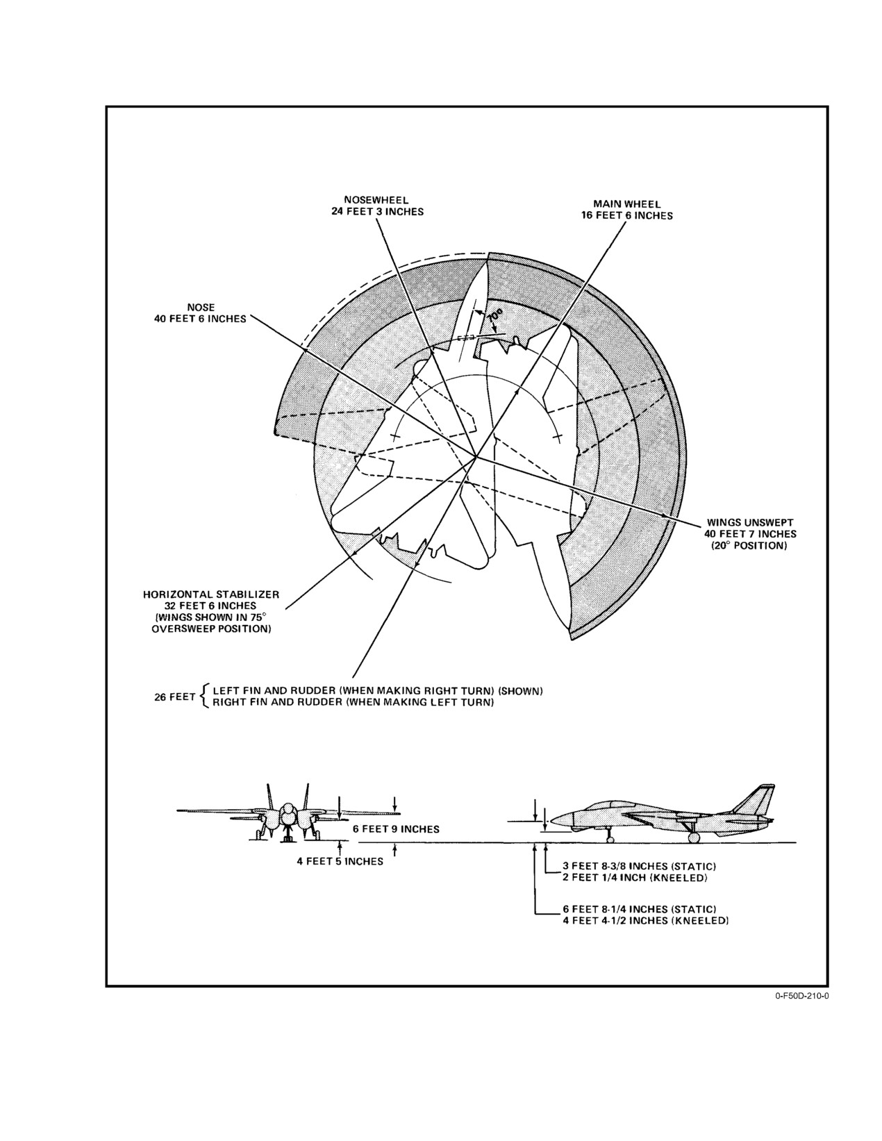
(Figure 7−3) using nosewheel steering, the inboard wheel
rolls backwards as the axis of rotation is between the main
gear. Because of the distance from the cockpit to the main
Failure to cycle nosewheel steering following
landing gear, the pilot should make allowance for such to
hook check will permit nosewheel steering cenĆ
prevent turning too soon and cutting corners short.
tering to remain engaged and can cause misposiĆ
7.4.5.3
Crew Comfort
tioning of the launch bar during catapult hookup.
This may result in launch bar disengaging from
Crew comfort during taxi operations is affected by the
shuttle during catapult stroke.
nose strut air curve characteristics, that maintains the strut in
the fully extended (stiff strut) position except during decelĆ
7.4.5
Taxiing
eration. Because of the wide stance of the main gear, differenĆ
tial application of wheelbrakes is effective for turning the
To set the aircraft in motion starting from a static posiĆ
aircraft without the use of nosewheel steering. Subsequent to
tion requires advancing the throttles slightly. While departĆ
flight, while returning to the line at light gross weights, one
ing the line area, flightcrew should clear the extremities of
engine may be shut down to prevent excessive taxi speeds at
the aircraft and the wings should remain at 68_ or in OV SW
IDLE thrust.
to minimize the span clearance. Once in motion, IDLE thrust
is normally sufficient to sustain taxi speeds and full noseĆ
wheel steering authority may be realized.
7.4.5.1
Taxi Speed
Taxi speed should be maintained at a reasonable rate
D On−deck engine operations for extended periĆ
consistent with traffic, lighting, and surface conditions.
ods can result in an unacceptable buildup in
Subsequent to flight, while returning to the line at light
fluid (hydraulic, engine oil, and IDG oil) temĆ
gross weights, the right engine may be shut down to prevent
peratures by taxing heat exchanger capacities.
excessive taxi speeds at IDLE thrust.
Since the left IDG supplies the majority of the
electrical power, it is more susceptible to
overheating than the right. Tail winds or large
power demand, or both, at high ambient air
temperatures, increase the chance of fluid
overtemperature.
D Before taxiing aircraft with wings in overĆ
D Since the outboard spoiler module is automatĆ
sweep and full wing fuel tanks, trim stabilizer
ically energized with the flap handle down
to zero to prevent wingtip and stabilizer interĆ
and weight on wheels, it is necessary to reĆ
ference.
strict the amount of flaps down operation on
D When taxiing across obstacles ensure noseĆ
the deck to prevent module fluid overheating,
wheel is centered to preclude launch bar from
or pull outboard spoiler module circuit
impacting nose wheelwell doors.
breaker.
ORIGINAL
7−18
NAVAIR 01−F14AAD−1
Figure 7Ć3.ĄTaxi Turn Radii (Maximum Nosewheel Steering 70_)
7−19
ORIGINAL
NAVAIR 01−F14AAD−1
7.4.6
Taxi Ċ Pilot
Hold in position for takeoff using the toe pedal brakes
with nosewheel steering engaged. Perform engine checks at
85 to 90−percent rpm. Select MIL on the roll and monitor
engine performance.
Taxiing with the left engine secured is not authoĆ
rized. Normal braking and nosewheel steering
control will be lost if the hydraulic transfer pump
Takeoffs with the HUD uncaged can produce
(BI−DI) fails while taxiing with the left engine
HUD symbology that is difficult to interpret durĆ
secured.
ing turning or asymmetric flight conditions. If
takeoff is anticipated following an uncaged landĆ
1. Parking brake Ċ Release.
ing, selecting the cage/seam switch on the inĆ
board throttle will ensure the HUD returns to the
2. Nosewheel steering Ċ Check.
caged format.
NWS ENGA light illuminates upon engagement.
Note
Check control and polarity in static position before
commencing to taxi.
D Do not use the parking brake to restrain the
Note
aircraft under the high−power conditions since
tire skid might result.
If nosewheel steering is inoperative, the emerĆ
D If static engine runup greater than 90−percent
gency gear extension air release valve may be
rpm is required, runup should be performed
tripped, which will prevent gear retraction.
one engine at a time.
3. Brakes Ċ Check.
7.4.7.1
Afterburner Takeoff
Check for proper operation by applying left or right
brake individually and observing brake pressure
Afterburner takeoffs are limited to single−engine, miniĆ
recovery to the fully charged condition.
mum afterburner takeoffs, waveoffs, bolters, or catapult
launches. Dual−engine afterburner and single−engine maxiĆ
4. Turn−and−slip indicator Ċ Check.
mum afterburner takeoffs, waveoffs, bolters, or catapult
launches are prohibited. Refer to Chapters 4 and 11.
5. Ordnance Ċ Safe.
Perform the following functions at prescribed
7.4.7.2
Brake Release
location prior to takeoff in accordance with base
After takeoff power checks are completed and at a safe
operating procedures:
interval behind the preceding aircraft, release the toe pedal
brakes. Nosewheel steering should be used for directional
a. Missile seeker and tuning Ċ Check.
control during the initial takeoff roll. Although the rudder
b. Gun and external stores Ground Safety Pins
becomes effective at 40 to 60 knots, to ensure adequate direcĆ
Removed and Armed.
tional control in the event of an engine failure, nosewheel
steering should remain engaged until 100 KCAS. Refer to
7.4.7
Takeoff
NAVAIR 01−F14AAP−1.1 for nosewheel steering on and off
abort data.
The aircraft takeoff checklist should be completed
prior to calling for takeoff clearance, and all annunciator
Note
lights should be off, except NWS ENGA. Full flaps and slats
D Takeoffs performed with standing water on
are optional for all takeoff regardless of thrust or gross weight
the runway may result in unstable engine opĆ
conditions. Flightcrew should be operating in HOT MIC durĆ
eration because of water ingestion.
ing this phase of flight to enhance communications in event
of emergency. Upon tower clearance and after visually clearĆ
D The nose strut should return to the fully exĆ
ing the approach zone, the pilot should taxi onto the runway
tended position (+1.5° pitch attitude) upon
(take downwind side if another aircraft to follow) and roll
brake release; failure to do so will increase the
straight ahead to align the nosewheel and to check compass
takeoff ground roll. Use of differential brakĆ
alignment.
ing to control directional alignment should be
avoided because of its attendant effect on
ground roll distance.
ORIGINAL
7−20
NAVAIR 01-F14AAD-1
7.4.7.3
Takeoff Roll/Lift-Off
wings-level flight or effecting gradual turns with symmetric
thrust. Before reaching the flap (225 KCAS for 10_ flaps) and
Minimum ground roll takeoff procedures do not differ
gear (280 KCAS) limit speeds, the pilot should ascertain that
from the normal procedures. Maintain the control stick at the
all devices are properly configured for higher speed flight.
trimmed condition during the prerotation ground roll phase
The combined hydraulic system nonflight essential compo-
to minimize aircraft drag. After the pre-computed rotation
nents (landing gear, brakes, and nosewheel steering) may be
speed (refer to NAVAIR 01-F14AAP-1.1), smoothly pull the
isolated by selecting FLT on the hydraulic isolate switch. A
control stick aft to position the HUD waterline at a 7_ to 10_
gradual climbout pitch attitude should be maintained until
pitch attitude until safely airborne. With the flaps down, the
intercepting the optimum climb speed. A recheck of engine
aircraftseemstoballoonfrom therunwayina near-levelnose
instruments and configuration status should be performed
attitude with a more docile transition toflight thancharacter-
after cleanup during the climbout phase.
istic of swept-wing aircraft.
7.4.8
Flaps-Up Takeoff
Note
Before the takeoff roll, the procedures for flaps-up
takeoff are identical to flaps down, except that the flaps re-
D The use of excessive back stick on takeoff
main retracted and only inboard spoiler brakes are available.
may cause the tail surfaces to stall, delaying
During the prerotation ground roll phase, maintain the con-
aircraft rotation and extending takeoff
trol stick at the trimmed condition to minimize aircraft drag.
distance.
At the pre-computed rotation speed, smoothly pull the con-
D Although on-deck pitch attitude rotation in
trol stick aft to position the HUD waterline at a 7_ to 10_ pitch
excess of 10_ provides marginal tail-ground
attitude until safely airborne.
clearance, the aircraft is airborne well before
such a phenomenon becomes a limiting
Do not exceed 10_ of pitch attitude until well clear of
factor.
the runway, as excessive noseup attitudes will cause the verti-
cal fins and tailpipes to contact the runway surface.
7.4.7.4
After Lift-Off
After lift-off, relax the aft stick force as the aircraft
accelerates toward an in-trim condition. Raise the landing
gear control handle after ensuring that the aircraft is definite-
ly airborne. Pitching moments associated with gear retrac-
Because of increased longitudinal control effec-
tion are negligible and a gear-up indication should be
tiveness with the flaps retracted, overcontrol of
achieved about 15 seconds after initiation.
pitch attitude during takeoff is possible. Large or
abrupt longitudinal control inputs should be
avoided until well clear of the runway.
Transition to flight will occur smoothly as compared to
the ballooning effect in flaps-down takeoffs. After main gear
Illumination of indexer lights is not a positive in-
lift-off, relax the aft stick force as the aircraft accelerates.
dication that the main landing gear are clear of
the runway. Raising the gear before a positive
Because of the smooth, flat transition to flight, care
rate of climb is established will result in blown
should be taken to avoid premature landing gear retraction
main tires.
and resulting blown tires. Raise the landing gear control
handle only after ensuring that the aircraft is airborne.
At approximately 180 KCAS (depending on longitudi-
nal acceleration) and at a minimum of 200 feet AGL, the
Note
FLAP handle can be placed in the UP position. A moderate
noseup pitching moment occurs during the flap and slat re-
D During flaps-up takeoffs, all flap/wing elec-
traction phase, which takes approximately 8 seconds. Imme-
tromechanical interlocks are removed from
diately after liftoff, do not attempt to counter a lateral drift
the CADC and wing-sweep control box,
caused by a crosswind condition. The use of large lateral
allowing possible inadvertent wing sweep in
control deflection should be avoided to keep from breaking
the event of a CADC failure.
out the wing spoilers, which have a negative effect on lift and
drag. Differential tail authority within the spoiler deadband
D Outboard spoilers are inoperative with weight
(½-inch lateral stick deflection) is adequate for maintaining
on wheels.
7-21
CHANGE 1
NAVAIR 01−F14AAD−1
7.4.8.1
Maneuvering Flaps Takeoff
Maneuvering flaps provide improved takeoff perforĆ
mance when compared to the flaps−up configuration and
eliminate the pitching moment associated with main flap and
In the event of an aborted takeoff, the aborting
slat retraction after takeoff. Slow−speed handling characterĆ
aircraft must immediately notify the other airĆ
istics are superior to the flaps−up configuration. Additionally,
craft and the tower. The aircraft not aborting
possible automatic maneuvering flap/slat extension during
should ensure positive wingtip separation is
rotation/transition to flight can be avoided by extending maĆ
maintained and select full military power to acĆ
neuvering flaps before takeoff.
celerate ahead of the aborting aircraft. This will
allow the aborting aircraft to move to the center
7.4.9
Formation Takeoff
of the runway and engage the available arresting
Formation takeoffs are permitted in the flaps−up/ maĆ
gear, if required.
neuvering flaps−down configurations for section only. HowĆ
ever, they shall not be permitted at night with: crosswind
component in excess of 10 knots; standing water on the runĆ
way; runways less than 8,000 feet long and 200 feet wide; or
with dissimilar aircraft. All aspects of the takeoff must be
briefed by the flight leader. Briefing should include flap setĆ
It is imperative that the wingman be alert for the
ting, power settings, use of nosewheel steering, abort proceĆ
overrunning situation and take timely action to
dures, and signals for power and configuration changes.
preclude this occurrence. Should an overrunning
situation develop after becoming airborne, the
7.4.9.1
Military Lead
wingman should immediately increase lateral
separation from the leader to maintain wing
With the completion of the takeoff checks, the lead
position. Safe flight of both aircraft must not be
aircraft will take position on the downwind side of the runĆ
jeopardized in an attempt to maintain position.
way with the wingman on a normal parade bearing with no
wing overlap. Upon signal from the leader, the engines will
7.4.10
Takeoff Aborted
be advanced to 90−percent power. When ready for flight, the
pilots shall exchange a thumbs−up signal. On signal from the
See Chapter 13, paragraph 13.1.
leader, brakes are released, MIL is selected, and the leader
then reduces power by 2 percent. Directional control is then
7.4.11
Takeoff Checklist
maintained with nosewheel steering until rudder becomes
Prior to takeoff, the checklist will be completed by the
effective. During takeoff roll, the leader should make only
challenge (RIO) and reply (pilot) method via the ICS on HOT
one power correction to enhance the wingman position. If
MIC as a double−check of the aircraft configuration status.
optimum position cannot be obtained, relative position
should be maintained until the flight is safely airborne. At the
For CV operations, steps 1 through 9 may be completed
precomputed rotation speed, the leader should rotate the airĆ
while tied down. For field operations, steps 1 through 14
craft 7_ to 10_ noseup on the HUD or MFD and maintain this
should be completed in the warmup area.
attitude until the flight is airborne. Turns into the wingman
RIO CHALLENGE
PILOT RESPONSE
should not be made at altitudes less than 500 feet above
ground level.
"CHECK OK, ACCUMULAĆ
1.
"BRAKES"
TOR PRESSURE UP"
7.4.9.2
Wingman
2.
FUEL TOTAL
"NORMAL FEED, AUTO
The wingman should strive to match the leader’s attiĆ
________lb"
TRANSFER, DUMP OFF,
tude as well as maintain parade bearing with wingtip separaĆ
TRANSFER CHECKED
tion. When both aircraft are safely airborne, the gear is reĆ
(If AUX tanks carried),
tracted on signal from the leader.
TOTAL ________
WINGS, EXT (If app.)
AFT AND LEFT ________
FORWARD AND
RIGHT ________
FEED TANKS FULL
BINGO SET
"
ORIGINAL
7−22
NAVAIR 01−F14AAD−1
RIO CHALLENGE
PILOT RESPONSE
7.4.12
Ascent Checklist
3.
CANOPY CLOSED,
CLOSED, LOCKS EN-
LOCKS ENGAGED,
GAGED, LIGHT OUT, SEAL
At level−off or 15,000 feet (whichever occurs first):
LIGHT OUT, STRIPES
INFLATED, HANDLE IN
ALIGNED, HANDLE IN
CLOSE POSITION"
1. Cabin pressurization Ċ Check.
CLOSE POSITION"
4.
SEAT . . . ARMED,
ARMED, STRAPPED IN
2. Fuel transfer Ċ Check.
STRAPPED IN EIGHT
EIGHT WAYS, PILOT/MCO
WAYS COMMAND
IN WINDOW" (as indicated)
3. Oxygen monitoring system Ċ Test.
EJECT" (as briefed)
5.
STAB AUG"
ALL ON"
6.
ATLS"
ON"
7.
ALL CIRCUIT
ALL IN"
BREAKERS SET"
Subsequent failure of the oxygen monitor system
8.
MASTER TEST
OFF"
will not be evident to the aircrew resulting in OB-
SWITCH"
OGS output of unknown quality.
9.
BI−DIRECTIONAL"
NORMAL"
10. COMPASS, STANDBY
COMPASS SYNCHRO-
Note
GYRO, TURN NEEDLE
NIZED, STANDBY GYRO
AND ALTIMETER"
ERECT, GOOD TURN
Pilot should ensure oxygen monitor test button is
NEEDLE, AND ALTIMETER
released as soon a possible after illumination of
SET (local settings)"
the OBOGS caution light to preclude unneces-
CV Ċ APPROACHING
sary depletion of the backup oxygen system.
CAT ON DIRECTOR’S SIGNAL
11.
OXYGEN"
OBOGS ON, MONITOR
7.4.13
In−Flight BIT
CHECKS GOOD"
If desired or required IBIT check should be run.
12.
WINGS (visually
"20", AUTO, NO WING−SWEEP
checked)"
CAWs"
1.
OBC disabled on pilot MASTER TEST PANEL Ċ
13.
FLAPS AND SLATS"
AS REQUIRED.
Check.
(visually checked)
2.
Verify MA ARM Ċ OFF.
14.
SPOILERS AND
"SPOILER MODULE ON,
ANTI−SKID"
SPOILER BRAKES
SELECTED" (field) "SPOILER
3.
Multifunction display.
MODULE ON, SPOILER
BRAKES OFF" (CV).
a. Select OBC basic format.
15.
TRIM"
0.0.0," (field) AS
b. Depress desired test.
REQUIRED (CV)
16.
SAHRS ATTITUDE
GOOD SAHRS ATTITUDE"
This initiates the in−flight BIT.
REFERENCE"
17.
DISPLAYS"
SET FOR TAKEOFF,
7.4.14
Preland and Descent
HUD CAGED"
1.
HOOK/HOOK BYPASS Ċ As Desired.
18.
HARNESS LOCKED"
LOCKED"
19.
CONTROLS"
"FREE, 33° AFT STICK, FULL
2.
Exterior lights Ċ As Desired.
(RIO visually check for
SPOILER DEFLECTION LEFT
full spoiler deflection)
AND RIGHT, HYDRAULICS
3,000 PSI"
3.
Displayed heading/BDHI Ċ Check With MAG
20.
ALL WARNING AND
"ALL WARNING AND
Compass.
CAUTIONS OUT"
CAUTIONS OUT"
4.
Wing−sweep switch Ċ As Desired.
ASHORE Ċ IN TAKEOFF POSITION
21.
ANTI−SKID/SPOILER
BOTH" (if operable)
5.
ANTI SKID SPOILER BK switch Ċ BOTH
BRAKES"
(If operable, CV−OFF).
6.
Altimeter Ċ Set.
7−23
CHANGE 2
NAVAIR 01-F14AAD-1
7. Radar altimeter — ON/BIT Check.
7.4.15
Pattern Entry
8. Fuel quantity and distribution — Check.
Entry to the field traffic pattern will be at the speed and
altitude prescribed by local course rules. When approaching
9. Armament — Safe.
the initial for the break, wings may be positioned manually
full aft to facilitate multiplane entry and break deceleration.
10. CANOPY DEFOG/CABIN AIR lever — DEFOG.
Break procedures shall comply with squadron, field, and/or
CV standard operating guidelines.
11. ANTI-ICE switch — AUTO/OFF.
7.4.16
Landing
12. Display mode — TLN.
13. Steering — AWL.
7.4.16.1
Approach
14. ARA-63/ACLS — ON/BIT Check.
At the abeam position for landing, the aircraft should
be at the prescribed altitude, trimmed up to 15 units AOA
15. RADAR WARNING RCVR PWR switch — OFF.
with the Landing Checklist completed.
16. ASPJ SYS switch — STBY.
Indicated airspeed should be cross-checked with gross
weight in wings-level flight to verify AOA accuracy. Direct
17. AN/ALE-47 DCDU, MODE/PWR switch — OFF.
lift control and the approach power compensator should be
18. RDR switch — STBY OR XMIT (pulse).
engaged as desired and checked for proper operation. The
turnoff from the 180_ position should be made based on
surface wind conditions and interval traffic (type, pattern,
touch-and-go or final landing, etc.) so as to allow sufficient
straightaway on final prior to touchdown.
The RIO should place RDR switch to STBY or
The quality of the approach and touchdown is
XMIT (pulse) on final approach to prevent un-
enhanced by starting from on-speed and on-altitude. The low
necessary exposure of flight deck personnel to
thrust required in the landing approach leaves little margin
RF radiation hazard.
for corrections from a high, fast position. Therefore, the pilot
must control these parameters precisely from the onset of the
19. [T] Resolution run — Complete.
approach to touchdown. Inertia and tail movement in con-
junction with engine thrust response characteristics dictate
Note
the use of small, precise corrections on the glideslope for the
most effective control technique.
Before reconnaissance system shutdown, run
film leader to protect target imagery from
The landing should be planned for the downwind side
inadvertent exposure during film download.
of the runway with traffic behind, or opposite, the nearest
traffic on landing rollout, or on the turnoff side of the runway.
20. [T] FRAME switch — OFF.
When surface wind is not a factor, pilots should practice
flying on the field optical landing aid system whenever pos-
21. [T] PAN switch — OFF.
sible. Fly the aircraft down to the deck without flaring so as
to accurately establish a touchdown point and achieve initial
22. [T] FILM switch — OFF.
compression of main gear struts to arm the spoiler brakes.
Note
Landing with DLC engaged will reduce the
amount of aft stick deflection available. DLC
Before selecting system switch to OFF, delay
should be deselected when established on land-
15 seconds for sensor shutdown, and mount to
ing rollout.
drive to vertical.
23. [T] TARPS control panel SYSTEM switch — OFF.
CHANGE 1
7-24
NAVAIR 01−F14AAD−1
7.4.16.2
Touchdown
Follow the Postlanding Checklist for proper configuraĆ
tion cleanup procedures. Clear the area behind before turning
To avoid tail−ground clearance problems, pitch attitude
off across the runway. The right engine may be shut down to
should not exceed 15 units AOA. At touchdown, immediateĆ
reduce residual thrust during low−gross−weight taxiing.
ly retard throttles to IDLE and confirm spoiler brake deployĆ
ment. Expeditiously lower the nosegear to the deck and,
7.4.16.4
Touch and Go
without allowing the nose to come up, smoothly program the
stick full aft.
For touch−and−go landings, MIL thrust is applied after
touchdown while thumbing speedbrakes in manually to conĆ
7.4.16.3
Rollout
figure the aircraft for a go−around. Automatic retraction of
The braking technique to be utilized with or without
speedbrakes occurs upon application of MIL thrust as a safety
antiskid selected is essentially the same; a single, smooth
backup mode of retraction. Control for rotation is greater
application of brakes with constantly increasing pedal presĆ
than experienced on takeoff, although the aircraft has the
sure. Do not pump the brakes. Directional control during
same basic lift−off characteristics. Fuel required per pass is
rollout may require some differential braking.
normally 300 pounds, contingent on traffic pattern.
Nosewheel steering may be used during rollout but it
7.4.16.5
Minimum Descent Rate Landings
must be engaged with the rudder pedals centered to avoid a
directional swerve upon engagement. Restrict the use of
Minimum descent rate landings are required for heavy
nosewheel steering during rollout until or unless required for
weight and landing gear emergency landings. Aircraft pitch
directional control. Under conditions of normal braking
attitude at touchdown is critical.
(antiskid selected), the antiskid system is passive and has no
effect on wheelbrake operation. However, if maximum
deceleration is desired, commence braking as the nose is
lowered and smoothly apply sufficient pressure to activate
the antiskid system. When an impending skid is sensed,
antiskid operation will result in a series of short wheel−
brake releases and a surging deceleration. Constant pedal
Do not exceed 10_ pitch attitude (on the waterĆ
pressure should be maintained. Approaching taxi speed
line) and 14 units AOA at touchdown to prevent
(about 15 knots), ease brake pressure and deselect antiskid.
speedbrake, exhaust nozzle, and/or ventral fin
damage.
After touchdown, throttles should be immediately
placed at the idle stops. The nosewheel should be lowered to
the ground, fully compressing the main landing gear struts.
Delaying either action will delay the deployment of ground
D If brakes are lost, release brake pedals and
roll braking spoilers and may increase landing rollout. AddiĆ
secure antiskid.
tionally, until ground roll braking spoilers are deployed,
lateral control remains responsive and pilot−induced lateral
D If antiskid is not deselected before 15 knots,
oscillation is possible. Aerodynamic braking should not be
continued hard braking could result in blown
used as speedbrakes, exhaust nozzle, and/or ventral fin damĆ
tires.
age may occur.
D Ensure feet are off brakes before crossing
field arresting gear.
The Fresnel lens may be used for precise glideslope
D If nosewheel steering hardover is suspected
control until arresting the approach rate of descent. Do not
upon engagement of NWS, deselecting NWS,
attempt to recenter a high ball in close. The approach should
lowering the hook, and/or differential braking
be flown on−speed at 15 units AOA. At approximately 30 feet
may be required to regain directional control.
AGL (2 to 3 seconds prior to touchdown), arrest the rate of
descent by a slight addition of power. Maintain approach
Note
attitude until touchdown. If the Fresnel lens is not available
or runway length is critical, fly a shallow approach to touchĆ
If maximum−effort braking or antiskid is not reĆ
down in the first 1,000 feet of runway. If runway length is
quired, or antiskid is not selected, delaying brake
critical, consideration should be given to reducing touchĆ
application until the aircraft aerodynamically
down speed by flying a no DLC approach.
decelerates below 80 knots greatly reduces the
possibility of blown tires and overheated brakes.
7−25
ORIGINAL
NAVAIR 01−F14AAD−1
7.4.16.6
Crosswind Landings
4. If a rollout landing is desired, touch down on centerĆ
line within the first 500 feet of runway. Landing rolĆ
Crosswind landings may be accomplished using either
lout procedures are the same as in a normal landing.
the sideslipped or crabbed technique, up to the crosswind
When directional control is clearly established, utiĆ
limit (20 knots). The roll rate command function and revised
lize normal braking. During the high−speed portion
spoiler gearing of the DFCS affect crosswind landing flight
of the landing roll, little or no deceleration may be
characteristics. During a sideslipped approach the DFCS
felt. Do not allow the aircraft to deviate from a
spoiler gearing schedule results in nearly immediate spoiler
straight track down the runway. If a skid develops,
breakout with lateral stick deflection from trim. This spoiler
release the brakes, and use rudders or nose−wheel
breakout may result in an overly sensitive roll response durĆ
steering for directional control. Reapply the brakes
ing lineup corrections. Because crabbed approaches are
cautiously. If the skid continues and adequate runĆ
flown without this offset lateral stick input and do not exhibit
way remains, select power as required and fly away.
this characteristic, pilots may find this technique easier for
If conditions do not permit flyaway, use the long
DFCS equipped aircraft.
field overrun gear if required. If the aircraft is leavĆ
ing the runway to an unprepared surface, secure
If a landing must be made in crosswind conditions in
both engines.
excess of the limits, the techniques must be changed. At some
crosswind component, the upwind wing will be raised excesĆ
Note
sively and, as a result, directional control will be marginal.
A blown tire on landing rollout may result in
It is estimated that this will occur with a greater than 25−knot
directional control difficulties, particularly at
crosswind component. If after touchdown the wing is raised
high speeds. Refer to Chapter 15, Landing EmerĆ
excessively, the spoiler brakes should be turned off and laterĆ
gencies, for blown−tire emergency procedures.
al stick applied to maintain a wings level attitude. If the
crosswind component is greater than 25 knots, do not arm the
7.4.17
Landing Checklist
spoiler brakes for landing and again maintain a wings level
attitude with lateral stick. It must be realized that antiskid
will not be available.
The placarded Landing Checklist should be completed
in sequence prior to arriving at 180_ abeam the touchdown
point. All checklist items are essential elements to be
7.4.16.7
Landing On Wet Runways
checked prior to each landing. With the ICS on HOT MIC,
the pilot shall call out the accomplishment of each step so that
If operable, antiskid shall be used on wet runways to
the RIO can double−check that all items have been
minimize the possibility of skidding or blowing tires. StandĆ
performed.
ing water greatly decreases braking effectiveness and may
cause total hydroplaning in certain conditions. (Refer to
1. Wing−sweep mode switch Ċ 20_ AUTO.
Chapter
18, Extreme Weather Operations.) Intermittent
puddles may cause wheels to lock while braking with antiskid
Check wings in AUTO sweep control mode and
not engaged. As the locked wheel leaves the puddle and
verify at 20_.
encounters a good braking surface, it will skid and blow
unless brake pressure is released. The following procedures
2. Wheels Ċ THREE DN.
are recommended when landing on a wet runway:
Check for wheels−down indication on all three gear,
1. Determine field condition before approach (braking
LAUNCH BAR light, and that gear transition light
action, crosswind component, arresting gear status).
is out. Check that brake accumulator pressure is
fully charged.
2. If adverse wind and runway conditions exist, make
a short−field arrested landing. In the event that the
During aircraft carrier (CV) qualifications and other
arresting gear is not engaged, execute a waveoff or
bolter as appropriate.
operations when the landing gear are not raised after
catapult launch, the pilot shall check the LAUNCH
3. Consideration should be given to reducing touchĆ
BAR advisory light is off prior to each landing.
down speed by flying a no−DLC approach. Plan the
3. SAS Ċ ON.
pattern to be well established on final in a wings−
level attitude (crab, if required) on speed. Land on
runway centerline, using normal FCLP landing
techniques.
ORIGINAL
7−26
NAVAIR 01−F14AAD−1
4.
Flaps Ċ Full DN.
7.
DCP Ċ Verify & record codes (FAIL, FLT, IBIT).
Check for flap and slat full−down indication and no
8.
Right throttle Ċ OFF.
FLAP light.
Note
5.
DLC Ċ Checked.
D Care should be taken when shutting down the
6.
Hook Ċ As Desired.
right throttle (with the left throttle at IDLE) to
Transition light should be out.
prevent inadvertent contact with the left
throttle, moving it aft to the cutoff position.
7.
Harness Ċ Locked.
D Run both engines at idle for 5 minutes before
8.
Speedbrakes Ċ EXT (out).
shutdown, especially if they have been run at
Check indicator for full speedbrake extension.
high power.
9.
Brakes Ċ Check.
9.
OBOGS master switch Ċ OFF (alert RIO).
10. Fuel Ċ Check.
10. OXYGEN SUPPLY valve Ċ OFF.
7.4.18
Postlanding Ċ Pilot
11. HYD TRANSFER PUMP switch Ċ SHUTOFF.
1.
Speedbrake switch Ċ RET.
(after BI−DI check)
2.
ANTISKID SPOILER BK switch Ċ OFF.
3.
Flaps and slats Ċ UP.
Check hydraulic transfer pump operation in the
combined−flight direction with the HYD PRESS,
Move FLAP handle UP and check for complete
OIL PRESS, R GEN, and R FUEL PRESS caution
retraction of main flaps and slats and auxiliary flaps
lights illuminated.
(flaps indicator Ċ 0_ and no FLAP caution light).
Check automatic deactivation of the outboard
12. Ejection seats Ċ Safe (coordinate with RIO).
spoiler module. As soon as the auxiliary flaps are
13. Ordnance Ċ Dearm (field).
retracted
(8 seconds) the wings will sweep aft if
commanded.
Dearm and safety ordnance in accordance with local
operating procedures.
4.
Wing−sweep mode switch Ċ BOMB.
14. Wheels Ċ Chocked.
15. Parking brake Ċ Pull.
Ensure that emergency WING SWEEP handle
and wings move to 55_.
Do not pull parking brake subsequent to a field
5. Emergency WING SWEEP handle Ċ OV SW.
landing if the brakes have been used extensively.
Raise handle and move aft to 68_. Raise handle to
16. V/UHF RADIO MODE switch Ċ OFF.
full−up extension and hold. When HZ TAIL AUTH
caution light goes out and the OVER flag appears,
17. Standby attitude gyro Ċ Cage.
move EMERGENCY WING SWEEP handle full
aft (75_ sweep position) and stow. Rotate handle
18. Left throttle Ċ OFF (alert RIO).
guard to stowed position.
Alert RIO and upon signal from plane captain,
6. Avionics Ċ OFF.
secure left engine. Check emergency generator
Turn off all avionics (data link, radar altimeter,
automatic operation upon shutdown.
displays, TACAN, ARA−63) except V/UHF radio.
19. EMERG generator switch Ċ OFF.
20. Lights Ċ OFF.
Turn off internal and external light switches.
7−27
ORIGINAL
NAVAIR 01−F14AAD−1
21. EJECT CMD indicator Ċ Verify PILOT.
7. SENSOR control panel
22. CANOPY handle Ċ Clear RIO To Open.
a. TCS FOV Ċ WIDE.
23. Flightcrew Ċ Egress.
b. TCS trim Ċ As Set.
7.5
RIO PROCEDURES
c. MVR source Ċ As Briefed.
7.5.1
Interior Inspection Ċ RIO
d. MVR RECORD Ċ OFF.
8. TACAN mode switch Ċ OFF.
9. JTIDS
a. MODE switch Ċ STBY.
NATOPS prohibits the attaching or stowing of
unauthorized equipment on or above the canopy
Note
rails during CV launch and arrestment, due to the
potential for missile hazard.
If the primary link system for the mission is
JTIDS, ensure the JTIDS MODE switch is in
1.
Circuit breakers Ċ Set.
STBY position. STBY provides the backup
battery power required to hold the crypto variĆ
2.
Left and right foot pedals Ċ Adjust.
ables and initialization data required for JTIDS
missions.
3.
Harnessing Ċ Fasten.
10. KY MODE/TACAN/CMD panel Ċ As Desired.
a. Leg restraint lines and garters Ċ Connect
11. KY−58
Ensure that leg lines are not twisted or looped.
a. PLAIN switch Ċ PLAIN.
b. Lapbelt Ċ Connect and Adjust.
Connect lapbelt straps and adjust snug so as to
b. Power switch Ċ OFF.
provide secure lap restraint in flight and seat kit
suspension for ground egress or ejection.
c. MODE Ċ As Desired.
c. Parachute release fittings Ċ Attach to Harness
d. FILL switch Ċ As Set.
Buckles.
12. V/UHF radio MODE switch Ċ OFF.
d. Anti−g and oxygen/communication leads Ċ
ATTACH.
13. RADAR COOLING switch Ċ OFF.
When connecting the oxygen/communication
14. EJECT CMD lever Ċ Set.
fitting, avoid twisting the hard hose.
Determined by squadron policy.
e. Inertia reel Ċ Check.
15. Data storage unit Ċ Secure.
Position shoulder harness lock lever forward to
lock position. Check that both shoulder straps
16. ARMAMENT control panel
lock evenly and securely. Move lever aft to
a. SEL JETT switch Ċ SAFE.
unlock harness.
b. MSL PREP switch Ċ OFF.
4.
ANT SEL panel Ċ As Desired.
c. MSL SPD GATE knob Ċ Per SOP.
5.
[T] TARPS control panel switches Ċ OFF.
d. MSL OPT switch Ċ NORM.
6.
ICS panel
e. JETTISON STA SEL switch Ċ OFF.
a. VOL knob Ċ Set.
17. Radio frequency control indicator Ċ As Desired.
b. Amplifier Ċ NORM.
c. Function selector Ċ COLD MIC.
ORIGINAL
7−28
NAVAIR 01-F14AAD-1
18. Standby attitude gyro
Caged, Turn Needle/Ball
Note
Centered.
The data-link MODE switch must be set to the
19. Clock — Set and Wind.
required link system
(JTIDS or TAC) for
appropriate MFD display processing.
20. Sensor hand control panel.
f. ADDRESS — Set.
a. RDR switch — OFF.
33. APX-76 — OFF.
b. FIRST switch — OFF.
c. TCS switch — OFF.
34. IFF MASTER knob — OFF.
35. MODE 4 switch — OUT.
21. Programmable tactical information display — As
Desired.
36. IFF ANT switch — DIV.
37. INTERIOR LIGHTS panel — As Desired.
Note
38. RADAR BEACON switch — OFF.
PTID NAV MODE and DEST switches are
inoperative.
39. RADAR BEACON MODE switch — As Desired.
22. DD power switch — OFF.
40. GND CLG switch — OFF.
41. SYS TEST-SYS PWR ground check panel —
23. MFD 3 power — OFF.
Closed.
24. ECM switch — OFF.
42. POWER SYS TEST switch — OFF.
25. NAV MODE switch — OFF.
7.5.2
Prestart — RIO
26. Data entry unit power — OFF
The following checks are performed by the RIO after
starting air and electrical power are applied prior to starting
27. RADAR WARNING RCVR
engines.
a. PWR switch — OFF.
b. DISPLAY TYPE switch — As Desired.
28. ASPJ
a. SYS switch — OFF.
D Starting air, which provides full ECS capabili-
b. BIT switch — OFF.
ty, must be connected to the aircraft with elec-
trical power to cool temperature-critical
c. TAC switch — NORM.
avionics.
29. MFA priority switch — NORM.
D If starting air is not available, a forced-air
ground cooling unit and servo air must be con-
30. AN/ALE-47 DCDU, MODE/PWR switch — OFF.
nected before turning on avionics equipment.
31. AN/ALE-47
Ground Test/Dimmer PNL
—
D If electrical power is not connected with spare
GUARD DOWN
starting air, the ECS will drive to full hot.
D To prevent overheating the outboard spoiler
32. Data-link panels
module, pull the OUTBD SPOILER PUMP
a. TEST/NORM/AJ switch — NORM.
circuit breaker (2B3) anytime external power
is connected and the flaps are extended.
b. FREQ selector — Set.
D Failure of the COOLING AIR light to illumi-
c. Power switch — OFF.
nate on external electrical power indicates a
miswired or failed sensor. The COOLING
d. REPLY switch — NORM.
AIR light will not be available to indicate a
e. MODE switch — TAC/JTIDS (as required).
subsequent ECS turbine failure.
7-29
CHANGE 1
NAVAIR 01−F14AAD−1
1.
Seat, ICS, and U/VHF foot switches Ċ Adjust.
mum clearance is afforded when canopy is tranĆ
siting fore and aft.
Adjust seat height so helmet is beneath the canopy
breaker. Adjust ICS and UHF foot pedal fore−aft
Note
position for sitting comfort.
If CLOSE does not close the canopy, depress the
2.
External power and air Ċ ON.
grip latch and release and push handle outboard
3.
ICS Ċ Check.
and forward into BOOST. If it is necessary to use
BOOST, the handle shall be returned to CLOSE
Verify two−way communications between flight
to avoid bleed off of pneumatic pressure.
crewmembers and adjust volume to a comfortable
level.
10. Acknowledge Ċ Ready To Start.
4.
DL, JTIDS, TACAN, and U/VHF Ċ Set.
7.5.3
Engine Start Ċ RIO
Set communications/TACAN/command control in
accordance with mission and flightcrew operating
The RIO must monitor pilot procedures and plane capĆ
procedures.
tain signals to ensure maximum safety during the engine start
sequence.
5.
Fuel quantity Ċ Check.
7.5.4
Poststart Ċ RIO
6.
Lights Ċ Check.
Check for illumination of console and instrument
1.
NAV MODE switch Ċ Align.
lighting.
2.
DD power switch Ċ ON.
7.
LTS test Ċ Check.
Failure to turn DD power on prior to RDR switch
Check that all caution and advisory lights and ECM
causes a false DD power fault indication in ORT.
lights illuminate.
3.
RDR switch Ċ XMIT.
Note
Verify that the SENSOR COND advisory light
During pilot INST test, the RIO should observe
illuminates.
fuel counter decrease to
2,000 pounds and
MASTER CAUTION and FUEL LOW lights
4.
RADAR COOLING switch Ċ ON.
illuminate.
Verify that the SENSOR COND advisory light goes
out.
8. Ejection seats Ċ ARMED.
Arm ejection seat by releasing catch and rotating
5.
MFD 3
SAFE/ARMED handle down to ARMED.
a. Power switch Ċ DAY/NIGHT/AUTO.
9. CANOPY handle Ċ CLOSE.
b. BRIGHTNESS and CONTRAST Ċ Set.
RIO will normally close canopy. Ensure verbal
6.
DEU Ċ On.
clearance from pilot. Check that CANOPY light
goes out with full forward transition of canopy into
7.
MSL PREP switch Ċ As Required.
the sill locks. Check that SEAT UNARMED light
does not illuminate.
8.
TCS switch Ċ ON.
9.
Align coordinates Ċ Verify/Update.
10. OXYGEN SUPPLY valve Ċ ON.
Flightcrews shall ensure that hands and foreign
objects are clear of front cockpit handholds, top
Turn OXYGEN SUPPLY valve ON, place mask to
of ejection seats, and canopy sills to prevent perĆ
face, and check for normal breathing and regulator
sonal injury and/or structural damage during
and mask operation. Turn OXYGEN SUPPLY valve
canopy opening or closing sequence. Only miniĆ
OFF; ensure oxygen flow has stopped.
ORIGINAL
7−30
NAVAIR 01-F14AAD-1
11. [T] TARPS control panel SYSTEM switch — RDY.
l. RANGE scale — As Required.
Observe DATA/MAN/Vg/H light illuminated.
m.THLD — As Required.
12. TACAN mode switch — T/R.
n. CLSN — OFF.
13. IFF MASTER knob — STBY.
o. BRIGHT control — Set.
a. Set CODE knob — As Required.
p. CONTRAST — Set.
b. IFF panel — Test.
20. Hand control — Set.
(1) MC switch — Out.
21. ASPJ SYS switch — STBY.
(2) Ml, M2, M3 — Test.
22. RADAR WARNING RCVR panel — Set.
a. Display type switch — NORM.
Select NORM and observe that TEST light
illuminates.
b. PWR switch — ON.
(3) MC — Test.
c. TEST switch — SPL.
Observe that TEST light illuminates.
d. MODE button — LMT.
c. IFF ANT switch — As Desired.
23. DATA LINK power — As Required.
14. JTIDS MODE switch — As Required.
24. D/L reply — As Required.
15. Communications — ON/Set.
25. AAI control panel — Set.
16. KY-58 — As Required.
a. TEST/CHAL CC switch — Test.
17. Standby attitude gyro — Erect.
Check DD display.
18. DD — Set.
26. AN/ALE-47
DCDU, MODE/PWR switch
—
STBY.
19. PTID controls — Set.
a. POWER — As Required.
Note
b. SYM ELEM — ON.
Ensure correct mission loadout is displayed in
LED window.
c. DATA LINK — As Required.
d. NON ATTK — As Required.
27. CANOPY DEFOG-CABIN AIR lever — CABIN
AIR.
e. RU — As Required.
28. Indicator lights — Test.
f. EXP — As Required.
g. LAUNCH ZONE — As Required.
29. [T] V/H check
a. Manual V/H thumbwheels set — 360 Knots/
h. JAM strobe — As Required.
200 Feet.
i. TCS — As Required.
b. V/H switch — Test.
j. RIDD — OFF.
c. Observe MAN V/H light is out.
k. PTID Display Mode — As Required.
d. V/H switch — MANUAL.
7-31
CHANGE 1
NAVAIR 01−F14AAD−1
30. [T] Vertical frame check
After INS ALIGN COMPLETE computer message or when
ready for takeoff:
a. Manual V/H thumbwheels set Ċ 350 Knots/
1,800 Feet
33. NAV mode switch Ċ INS.
b. FRAME switch Ċ VERT.
Observe MFD transition from align format. Wait
5 seconds.
c. FILM switch Ċ RUN.
34. NAV mode switch Ċ IFA.
Observe exposure interval of 1.0 second, frame
35. DEST data Ċ Verify.
camera green light illuminated, and check
camera frame counter for proper operation.
36. BRG/DIST to destination Ċ Check.
d. FILM switch Ċ OFF.
37. OWN A/C groundspeed Ċ Check.
38. MAG VAR Ċ Check.
e. FRAME switch Ċ VERT.
39. Notify pilot Ċ Ready To Taxi.
31. [T] PAN autocycle check.
7.5.5
Taxi Ċ RIO
a. PAN switch Ċ CTR.
b. FILM switch Ċ RUN.
The RIO primary responsibility during taxiing is to act
as copilot/safety observer. BIT checks may be performed
Observe exposure interval of 1.0 second, green
while taxiing, provided that RIO attention is not diverted
PAN light illuminated, and check camera frame
from copilot/safety observer duties.
counter for proper operation.
1. Record ORT/IBIT and maintenance display results
on BER form.
c. PAN switch Ċ LEFT or RIGHT.
2. OWN A/C groundspeed Ċ Check.
Observe exposure interval of 2.0 seconds, PAN
Own−aircraft groundspeed when stopped should be
go light illuminated, and check camera frame
less than 3 knots.
counter for proper operation.
3. [T] OWN A/C altitude Ċ CHECK.
d. FILM switch Ċ OFF.
7.5.6
In−Flight Reconnaissance System
Check Ċ RIO
En route to target area:
1. [T] FRAME switch Ċ VERT.
Do not run PAN BIT (it may cause film jams).
2. [T] PAN switch Ċ CTR.
32. [T] PAN pulse mode check.
3. [T] FILM switch Ċ RUN.
a. Manual V/H thumbwheel set Ċ 350 Knots/
13,500 Feet.
Run only long enough to check operation and
observe FRAME, and PAN green lights illuminated
b. PAN switch Ċ CTR.
and check frame and foot counters.
c. FILM switch Ċ RUN.
4. [T] FILM switch Ċ OFF.
5. [T] PAN switch Ċ LEFT or RIGHT.
Observe exposure interval of 5.0 seconds, green
PAN light illuminated, and check camera frame
6. [T] FRAME switch Ċ FWD.
counter for proper operation.
Note
d. FILM switch Ċ OFF.
Prior to selecting FILM switch to RUN, delay
15 seconds for camera positioning.
e. PAN switch Ċ OFF.
ORIGINAL
7−32
NAVAIR 01−F14AAD−1
7. [T] FILM switch Ċ RUN.
If not corrected:
Run only long enough to check operation and
2.
[T] FRAME switch Ċ OFF.
observe FRAME and PAN green lights illuminated
and check for proper film counter operation.
8. [T] FILM switch Ċ OFF.
9. [T] FRAME switch Ċ OFF.
D Initiate corrective action only one time.
10. [T] PAN switch Ċ OFF.
D If mount light does not go off, secure sensor
Note
and wait 5 minutes to try again.
Keep manual V/H thumbwheels matched with
7.5.7.3
Panoramic Camera Failure
actual altitude and airspeed to avert possible
degraded imagery if an automatic shift to the
1.
[T] FILM switch Ċ Cycle OFF/RUN.
manual mode occurs.
2.
[T] FILM switch Ċ OFF.
7.5.7
TARPS Degraded Mode Procedures
3.
[T] PAN switch Ċ Cycle OFF/CTR.
4.
[T] FILM switch Ċ RUN.
If not corrected:
Prior to initiating corrective action on malfuncĆ
5.
[T] FILM switch Ċ OFF.
tioning sensors, ensure that other sensors are
either in OFF or STBY.
6.
[T] PAN selector Ċ LEFT or RIGHT.
7.5.7.1
Serial Frame Camera Failure
7.
[T] FILM switch Ċ RUN.
1. [T] SYSTEM switch Ċ Cycle OFF/RDY.
If not corrected:
2. [T] FILM switch Ċ Cycle OFF/ RUN/OFF.
8.
[T] FILM switch Ċ OFF.
3. [T] FRAME switch Ċ Cycle OFF/VERT or FWD.
9.
[T] PAN selector−−OFF.
4. [T] FILM switch Ċ RUN.
5. [T] FILM switch Ċ OFF.
6. [T] V/H Ċ MANUAL.
7. [T] Thumbwheels Ċ Set High Vg/H Value.
Do not initiate BIT.
8. [T] FILM switch Ċ RUN.
7.5.7.4
Manual V/H Failure
If not corrected:
1.
[T] Thumbwheels Ċ 350 Knots/200 Feet.
9. [T] FILM switch Ċ OFF.
2.
[T] V/H switch Ċ Test.
10. [T] FRAME switch Ċ OFF.
3.
[T] MAN V/H light out Ċ Good Test.
7.5.7.2
Mount Failure
4.
[T] MAN V/H light on Ċ Thumbwheel Failure.
1. [T] FRAME switch−Cycle to Opposite Position.
7−33
ORIGINAL
NAVAIR 01−F14AAD−1
7.5.8
Postlanding Ċ RIO
17. Standby attitude gyro Ċ CAGE.
18. OXYGEN supply valve Ċ OFF.
Note
Before shutdown, run IBIT. Note results on BER
19. V/UHF radio MODE switch Ċ OFF.
card.
20. [T] TARPS control panel switches Ċ OFF.
1.
Ejection seat Ċ SAFE (coordinate with pilot).
21. DEU Ċ OFF.
2.
EJECT CMD lever Ċ PILOT.
22. MFD Ċ OFF.
3.
Harnessing Ċ Unstrap.
23. Report Ċ Ready for Shutdown.
4.
Radar beacon Ċ OFF.
After shutdown of both engines:
5.
IFF Ċ MODE 4 HOLD, Then OFF.
24. CANOPY handle Ċ OPEN (alert pilot).
6.
Data link Ċ OFF.
25. Flightcrew Ċ Egress.
7.
ASPJ SYS switch Ċ OFF.
7.6
HOT REFUELING PROCEDURES
8.
INS Ċ VIS FIX.
Before commencing ground hot refueling operations,
9.
NAV MODE switch Ċ OFF.
a qualified groundcrew shall inspect the exterior of the airĆ
craft for any discrepancies that might be hazardous to refuelĆ
10. RECORD switch Ċ OFF.
ing or further flight operations. One groundcrew shall remain
in a position on the right side of the aircraft within view of
Requires at least
20 seconds to allow tape
to
both the pilot and refueling crew. Any hazardous condition
unthread prior to removal of electrical power.
requires the immediate termination of refueling operations.
11. IRST switch Ċ OFF.
After refueling, the flightcrew should refer to approĆ
12. RDR switch Ċ OFF.
priate checklists to configure the aircraft for takeoff, dependĆ
ing on intentions.
13. DD power switch Ċ OFF.
1. Fire extinguishing equipment Ċ Available.
14. RADAR COOLING switch Ċ OFF.
2. All emitters Ċ STBY or OFF.
15. TACAN mode switch Ċ OFF.
3. Right throttle Ċ OFF.
16. JTIDS MODE switch Ċ STBY/OFF.
4. Wheels Ċ Chocked.
Note
5. Parking brake Ċ Pull.
If network operations are anticipated within
24 hours, select STBY; otherwise, select OFF. Do
not leave the system in DATA SILENT or NORM
for more than 90 seconds without electrical powĆ
er or the battery will be depleted.
ORIGINAL
7−34
NAVAIR 01−F14AAD−1
4.
Left engine Ċ IDLE.
5.
Right engine Ċ IDLE.
6.
Displays Ċ ON.
If heavy braking is used during landing or taxing
followed by application of the parking brake,
7.
OBC Ċ Select.
normal brake operation may not be available
following release of the parking brake if the
8.
SW COOL Ċ NORM.
brakes are still hot. Check for normal brake
9.
OBC Ċ Deselect.
operation after releasing the parking brake and
before commencing taxiing.
10. Hook operation Ċ Check.
6. REFUEL PROBE switch Ċ FUS EXTD/ALL
11. Takeoff Checklist.
EXTD (as desired).
7. WING/EXT TRANS switch Ċ As Desired.
12. Ordnance crew Ċ Arm.
Note
7.7.2
RIO Procedures
D If external tanks or wings accept fuel in
1.
NAV MODE switch Ċ CV ALIGN.
FUS EXTD, select ORIDE on WING/EXT
TRANS switch.
2.
CAINS/WPT Ċ Select.
D If wings or external tanks do not accept fuel
3.
MFD 3 Ċ ON.
in ALL EXTD, select FUS EXTD and turn
WING/EXT TRANS switch OFF.
4.
Alignment coordinates Ċ Verify/Update.
8. REFUEL PROBE switch Ċ RET.
5.
Seat Ċ Arm.
6.
RDR switch Ċ XMIT.
9. WING/EXT TRANS switch Ċ OFF.
7.
TCS switch Ċ ON.
7.7
DECK−LAUNCHED INTERCEPT
8.
IRST switch Ċ ON.
PROCEDURES
9.
MSL PREP switch Ċ NORM.
Note
10. [T] TARPS control panel SYSTEM switch Ċ RDY.
These procedures assume that a quick reaction,
full−mission−capable launch is essential. Prestart
11. Takeoff Checklist (complete non−OBC functions).
procedures and cockpit configuration may vary
in accordance with airwing policy and specific
When ALIGN QUALITY ≤2.0:
EMCON conditions. All CNI equipment as apĆ
12. NAV MODE Ċ INS.
plicable, should be placed in ON or STBY, all
SAS switches on, and the HYD TRANSFER
13. Wait for IFA AVAILABLE." NAV MODE Ċ IFA.
PUMP switch should be in NORMAL before
application of electrical power. The LTS, INST,
14. Ordnance crew Ċ Arm.
EMERG GEN, and DFCS IBIT tests on
MASTER TEST panel should be conducted and
Note
verified during periodic aircraft turnups. ComĆ
pliance with the Takeoff Checklist is mandatory
D Sparrow tune occurs after CW is enabled and
to ensure proper aircraft configuration before
can complete after transmitter timeout.
launch.
D PH attack capability is present after launch
7.7.1
Pilot Procedures
and Sparrow tune occurs automatically whenĆ
ever CW is enabled.
1. External electrical power Ċ ON.
2. Seat Ċ ARM.
3. Fire detect Ċ Check.
7−35
ORIGINAL
NAVAIR 01−F14AAD−1
7.8
HOT SWITCH PROCEDURES
11. THROTTLE MODE switch Ċ MAN.
12. Throttle friction lever Ċ Increase.
7.8.1
On−Deck, Maintenance Troubleshooting
13. Ejection seats Ċ SAFE.
14. Flightcrew Ċ Unstrap.
15. Cockpit Ċ Check for FOD.
16. CANOPY handle−OPEN.
To ensure a safe in−cockpit maintenance troubleĆ
17. Flightcrews Ċ Switch.
shooting evolution, the following procedures
should be used.
18. Flightcrew Ċ Strap In.
1. Parking brake Ċ Pull.
19. Ejection seats Ċ Armed.
20. CANOPY handle Ċ CLOSE.
2. THROTTLE MODE switch Ċ MAN.
21. FIRE DET/TEST Ċ TEST.
3. Throttle friction lever Ċ INC.
22. THROTTLE MODE switch Ċ BOOST.
4. Ejection seats Ċ SAFED, CMD − PILOT.
23. Throttle friction lever Ċ As Desired.
5. Flightcrew Ċ Remain strapped in.
24. Left engine Ċ Start.
25. RDR switch Ċ STBY.
7.8.2
Hot Switch Procedures
26. TCS switch Ċ STBY.
Increased potential hazards exist in hot switch operaĆ
27. IRST switch Ċ STBY.
tions when an engine is running with canopy open and front
seat unoccupied. To minimize this potential hazard, miniĆ
mum time should be spent in this condition. Pilot switch
should be expedited and crew unstrap should be done with
canopy closed. Pilot−to−pilot brief should be accomplished
with a pilot in the aircraft.
Ensure TARPS maintenance personnel have
loaded sensors and cleared aircraft before iniĆ
Note
tiating power to TARPS pod.
The RIO will vacate the aircraft first. When the
RIO is on the ground, flight deck, or hangar deck,
28. [T] TARPS control panel SYSTEM switch Ċ RDY.
the pilot will exit. This is particularly important
during shipboard operations.
Note
1. Parking brake Ċ Pull.
The Poststart Checklist shall be completed with
respect to aircraft configuration and switch posiĆ
2. HYD TRANSFER PUMP switch Ċ NORMAL.
tions prior to taxi.
3. RDR switch Ċ OFF.
7.9
FIELD CARRIER LANDING PRACTICE
4. IRST switch Ċ OFF.
5. TCS switch Ċ OFF.
7.9.1
Preflight Inspection
6. RECORD switch Ċ OFF.
A normal preflight inspection will be conducted with
7. [T] TARPS control panel SYSTEM switch Ċ OFF.
specific attention directed to tire condition, nosestrut extenĆ
sion, AOA probe conditions, and windshield cleanliness.
8. Left throttle Ċ OFF.
Check that the hook bypass switch is in FIELD.
9. ASYM LIMITER switch Ċ ON (guard down).
10. ENG MODE SELECT Ċ PRI.
ORIGINAL
7−36
NAVAIR 01−F14AAD−1
7.9.2
Takeoff
tion (see Figure 7−4). The length of the groove should be
adjusted to give a wings−level descent on the glideslope of 15
The takeoff will be individual.
to 18 seconds (approximately ¾ mile). For maximum gross
weight at touchdown, refer to Chapter 4, Operating LimitaĆ
7.9.3
Radio Procedures and Pattern Entry
tions. The turn to the downwind leg should be commenced
after climbing to pattern altitude (600 feet AGL) utilizing
A radio check with Paddles is advisable before pattern
30_ angle of bank and 150 KCAS. Turning from the 180_,
power should be adjusted to maintain optimum angle of atĆ
entry to confirm Charlie time. Approaches to the field for
break will be controlled by the tower and then switched to
tack. A gradual descent may be commenced at this position
with a minimum altitude of 450 feet AGL at the 90_ position
Paddles for FCLP pattern control. At no time will an aircraft
remain in the pattern without a UHF receiver. On each
and 350 feet AGL as a minimum until the pilot is receiving
succeeding pass, the following voice report will be made at
glideslope information. At approximately 45_, the meatball
appears on the Fresnel lens. Fly a rate of descent such that
normal meatball acquisition positions:
the ball is centered as the aircraft arrives wings−level in the
1. Side number
groove. For manual, automatic, and DLC approach techĆ
niques, refer to Carrier−Based Procedures, Chapter 8.
2. TOMCAT
7.9.5
Night FCLP
3. Ball/Clara
All provisions that apply to day FCLP also apply to
4. Fuel state
night FCLP, plus the following items:
5. Type of approach, if appropriate
(automatic,
1. External lights Ċ BRIGHT and STEADY.
degraded, etc.).
2. Hook bypass switch Ċ FIELD.
7.9.4
Pattern
When comfortably situated in the pattern, instruments
The pattern should be a racetrack with the
180_
should be flown as much as possible up to the 45_ position.
approximately 1¼ miles abeam at 600 feet above field elevaĆ
7−37
ORIGINAL
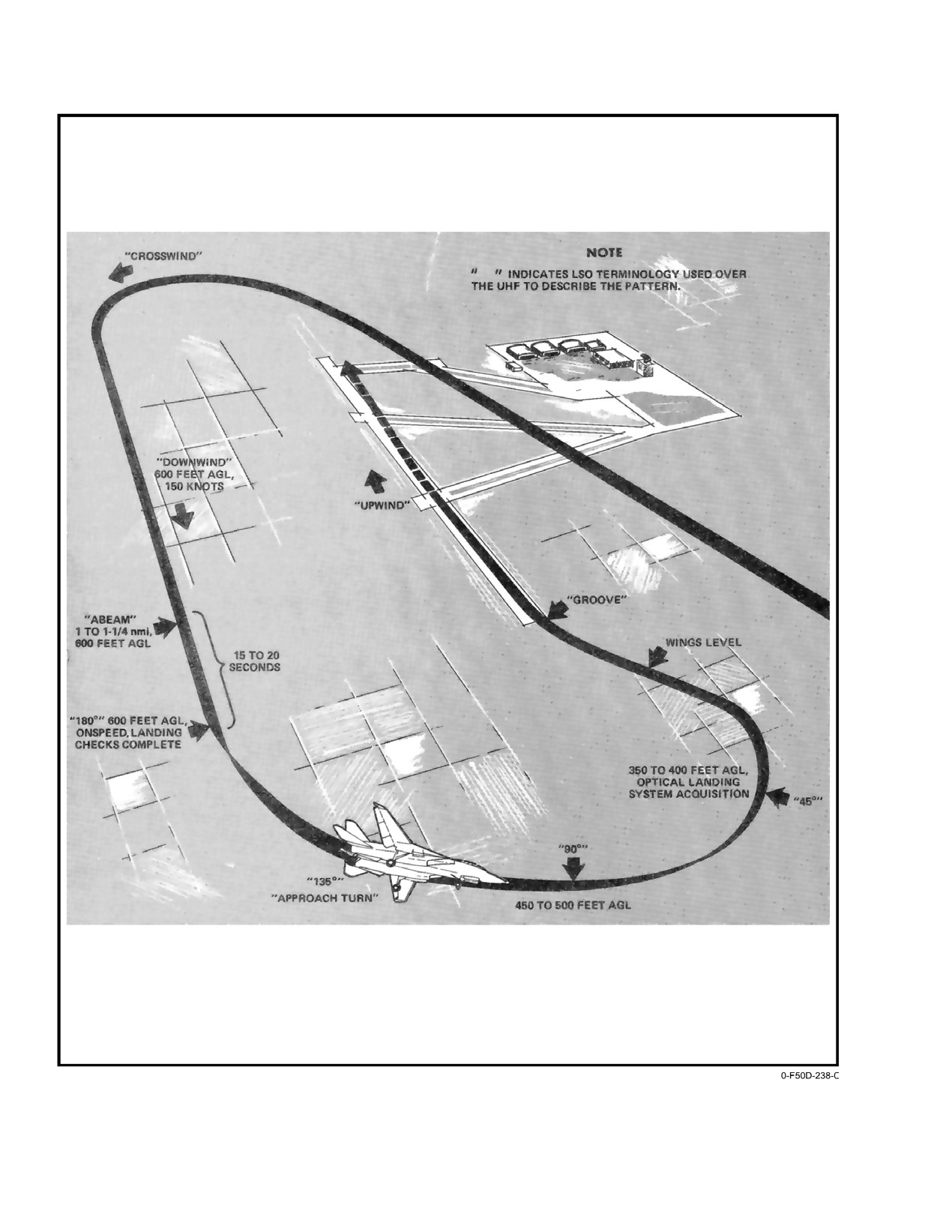
NAVAIR 01−F14AAD−1
Figure 7Ć4.ĄField Carrier Landing Practice
ORIGINAL
7−38
NAVAIR 01−F14AAD−1
CHAPTER 8
Carrier−Based Procedures
8.1
CARRIER PREFLIGHT
8.2
START AND POSTSTART
8.1.1
Launch
Shipboard start and poststart procedure abbreviations
of the shore−based checklists are as delineated for the
Applicable aircraft launching bulletins, the CV and
poststart−pilot procedures. Certain steps are omitted because
LSO NATOPS Manuals and the pertinent CV air operations
aircraft are spotted too close together to allow the wings to
manual shall be read by all flight crewmembers prior to
be swept forward while tied down. Cranking the left engine
carrier qualification. In addition, the predeployment lecture
prior to starting the right, as outlined in the shore−based
syllabus contained in Chapter 1 of the CV NATOPS Manual
procedures, will ensure that auxiliary brake pressure is
shall be completed.
available and will ensure that backup flight control module
8.1.2
Briefing
is full of hydraulic fluid prior to cycling.
A thorough briefing shall be accomplished by the flight
8.2.1
Carrier Alignment
leader prior to launch. This briefing should call particular
Carrier alignment of the INS and SAHRS concurrently
attention to current BINGO fields, emergency procedures
or of the INS alone can be accomplished using SINS data
peculiar to carrier operations, operating area NOTAMs, fuel
or manually entered ship’s position, speed, and heading.
management, and ship NAVAID status. Aircraft configuraĆ
A stored heading SINS alignment is also available.
tion, gross weight, expected WOD, and applicable launch
trim settings will be verified prior to man−up.
8.2.1.1
Concurrent SINS Alignment
8.1.3
Preflight
For either data−link or deck−edge−cable transmission of
SINS data:
Preflight inspection should be accomplished with
particular attention given to nosestrut, main landing gear
1. DATA LINK power switch ON.
tires, hook, and underside of the fuselage. Note carefully the
2. DATA LINK MODE switch CAINS/WPT.
actual wing sweep, the lateral spacing between parked
aircraft, and the general direction of engine exhaust. Do not
3. Verify parking brake is set.
preflight the aircraft topside aft of the bleed air doors if
Note
spotted with the tail outboard of the safety nets. In the
cockpit, particular attention should be given to the flightcrew
Application of SAHRS power prior to selecting
displays to ensure that they are properly secured and that the
CV ALIGN will not allow SAHRS to properly
retaining devices have been installed. Ensure that the WING
align.
SWEEP handle is secure in the oversweep position when
4. NAV MODE switch CV ALIGN.
applicable. If the wings are not in oversweep, ensure that
the emergency WING SWEEP handle position corresponds
5. Select OWN A/C MFD format by depressing DATA
with the actual wing position. Leave the emergency
pushbutton on MFD MENU1 display. The CV SINS
WING SWEEP handle guard up, extend the emergency
DATA format will appear.
WING SWEEP handle, and pull WING SWEEP DRIVE
6. Verify that SHDG is not boxed. If it is, depress the
NO. 1 and WG SW DR NO. 2/ MANUV FLAP circuit
SHDG pushbutton to unbox it.
breakers
(LD1, LE1). Crossbleed starts should not be
performed unless the area aft of the aircraft is clear. Tiedowns
7. Monitor the progress of alignment by observing the
should not be removed and engines should not be started
QUAL and TIME acronyms and the align scale on
unless the auxiliary brake air pressure gauge indicates a full
the MFD OWN A/C format. The SINS (ship) latiĆ
charge.
tude, longitude, and INS north and east velocities
can be evaluated on the MFD OWN A/C format. An
INS ALIGN COMPLETE message will normally
occur in 7 minutes. At this time the align quality
should be below 1 nm per hour.
8−1
ORIGINAL
NAVAIR 01−F14AAD−1
Note
1. Repeat steps
1 through
7 of concurrent SINS
alignment.
Do not select SAHRS during CV ALIGN to
check alignment progress. Wait until INS alignĆ
2. Verify that SHDG is boxed on CV SINS DATA MFD
ment is complete and INS has been selected on
format.
the NAV MODE switch before selecting
3. Repeat steps 9 and 10 of concurrent SINS alignĆ
SAHRS.
ment.
8.
SAHRS alignment progress may be monitored at
this time by selecting the NAV page.
8.2.1.3
Concurrent Manual Carrier Alignment
Note
The INS and SAHRS will initiate ground alignments if
there is no SINS data. The CV MANUAL format will be
D The SAHRS alignment process will initiate
after the INS determines a valid true heading
displayed after the ship’s data is entered.
(approximately at INS quality value of 5).
1. Repeat steps 1 through 8 of concurrent SINS carrier
SAHRS quality value should reinitiate to
align.
approximately 31.2 at that time.
Note
D If power has been applied to the aircraft for an
extended period of time prior to INS CV align
If the SINS or data link is not operating or if a
being initiated, the SAHRS may complete a
manual carrier alignment is desired, skip steps 2
ground align (NORM) and a SAHRS comĆ
and 3.
plete message appears on the MFD. After the
2.
Enter best knowledge of ship’s latitude, longitude,
INS CV align is initiated, the SAHRS will iniĆ
speed, and heading via the DEU or DD. When
tiate a concurrent CV align normally, but
the DATA pushbutton on the MFD is depressed, the
another SAHRS align complete message may
CV MANUAL DATA format appears.
not appear.
9.
It is advisable to continue alignment after appearĆ
Note
ance of the INS ALIGN COMPLETE message if
D If SINS is restored, MAN must be unboxed on
time permits. When ready to take the alignment, the
the CV DATA format in order to return to a CV
inertial navigation mode may be selected by setting
RF alignment.
the NAV MODE switch to INS, waiting for 5 secĆ
onds, then setting it to IFA. The RIO may take the
D Entry of VLA is never required for manual
alignment anytime the QUAL reaches 1.0 nm per
carrier alignment.
hour. The NAV Mode switch should be rotated to the
D When using the DEU, data entry is made via
INS position for a few seconds then rotated to the
the DEU CV ALIGN format, using the LAT,
IFA position. This places the navigation system in
LONG, CSPD and CHDG pushtiles, and the
the INS/GPS mode of operation.
appropriate quadrant and numerals.
Note
D Data entry using the DD requires selection of
Although SINS alignment normally requires no
the NAV category from the MFK pushtile and
entry of data, if a SINS alignment takes place at
the boxing of the OWN A/C acronym prior to
any carrier location other than the flight deck,
entering the carrier latitude and longitude via
then it is advisable to enter the correct vertical
the DD LAT, LONG, quadrant and numeral
lever arm via the DEU. This is the height in feet
pushtiles. Entry of carrier speed and heading
of the aircraft INS above the carrier SINS locaĆ
via the DD requires the boxing of the WIND
tion. This entry can be made only via the DEU by
acronym prior to using the DD SPD, HDG and
calling up the DEU CV ALIGN page and deĆ
numeric pushtiles.
pressing the VLA option key.
3.
Repeat steps 9 through 11 for concurrent SINS
8.2.1.2
Concurrent SINS Stored Heading Carrier
carrier align.
Alignment
Note
Perform a reference alignment by following the SINS
carrier align procedure in paragraph 8.2.1.1. When the INS
In concurrent manual carrier align, the INS
ALIGN COMPLETE message appears on the HUD/VDI
ALIGN COMPLETE computer message may
formats, return the NAV MODE switch to OFF.
take 15 minutes or longer to appear. The navigaĆ
tion quality at this time may not be better than
3 nm per hour. Because of the extensive alignĆ
ORIGINAL
8−2
NAVAIR 01−F14AAD−1
ment time, it may be necessary to launch prior
Note
to the receipt of the INS ALIGN COMPLETE
INS alignment to GPS data via the INS/GPS
computer message.
mode is not always optimum from a cold start. It
8.2.2
SAHRS Standalone Carrier Alignment
may require up to 10 minutes (plus up to 2 minĆ
utes for MAGR initialization), compared to only
The SAHRS standalone CV alignment mode is manuĆ
5 minutes for a normal carrier (CV) alignment. If
ally selected via the SAHRS ALIGN MFD format by
movement of the aircraft during alignment is not
depressing the SAHR and then CV pushbutton. There are two
anticipated, a normal concurrent CV alignment
SAHRS standalone align modes. Which mode obtained
followed by placing the NAV MODE switch to
depends on when CV is selected. If CV is selected prior to the
INS momentarily, then selecting IFA (In−Flight
INS determining true heading (approximately INS quality of
Alignment) may be more expeditious and will
5) and initiating the SAHRS CV concurrent align, a SAHRS
yield the same system accuracy.
standalone align is commanded when the SAHRS has no
heading information.
Global Positioning System satellite acquisition norĆ
mally takes from 90 seconds to 3 minutes, depending on
Note
location and LOS (line−of−sight) blockage by other aircraft
Currently there is no indication on the MFD disĆ
and carrier island, etc.
plays that the SAHRS has gone into the standaĆ
To get an IFA Alignment on deck, perform the
lone mode except the SAHRS quality value will
following steps:
remain 10.0, the timer will be 00, SAHRS conĆ
current CV align will not initiate, and there will
1. Place the NAV MODE switch in IFA at application
of aircraft power.
be no attitude information available from the
SAHRS for up to 6 minutes or more. Reinitiating
2. Verify OWN A/C position is correct. Verify correct
the INS alignment will allow a concurrent alignĆ
date and time on the GPS Status page. If satellites
ment to occur.
have been acquired, the OWN A/C data page will
show own aircraft position based on GPS, if GPS is
The SAHRS has no true standalone carrier align mode
boxed.
like the INS. During concurrent INS/SAHRS carrier align
modes, the SAHRS depends on the INS to provide an initial
Note
input of true heading. Since this is not available in SAHRS
If GPS data is lost during alignment, the navigaĆ
standalone carrier alignment, when the SAHRS CV pushĆ
tion system will go to align hold.
button is depressed in SAHRS standalone operation, it
3. Monitor the GPS Status page to ensure satellites are
is commanded to a DG mode. Once the parking brake is
acquired within a few minutes of placing the NAV
released a DG heading can be entered via the DEU. When the
MODE switch out of the OFF position to IFA. IFA
aircraft is airborne, the slaved mode can be selected or if a
alignment will not commence until satellites are
system velocity source is present, in−flight restart can be
acquired. If satellites are not acquired after a few
selected to bring the SAHRS to a normal operational mode.
minutes, transition to a normal CV alignment (on
If CV is selected after the INS has initiated the SAHRS
NAV Mode Switch select OFF then CV).
CV concurrent alignment, the SAHRS alignment proceeds
4. The alignment will progress on its own. When the
but is no longer receiving updated position and velocity
QUAL gets to 1.0, the system will automatically
information from the INS. The alignment will be considerĆ
take the alignment and display the INS ALGN
ably slower than concurrent alignment. The SAHRS is
CMPLT message. You can taxi and even take off
commanded to NORM mode. An in−flight restart may or may
without disrupting the align process.
not be required depending on the SAHRS alignment quality.
Note
SAHRS cannot be commanded to a CV mode unless
The pilot will not have an FPM (Flight Path
the INS is in CV. If the INS is unavailable, the SAHRS will
Marker) until the alignment is complete.
attempt a normal ground align.
5. If the system loses GPS quality at any time during
8.2.3
GPS On−Deck IFA Alignment
flight or while on the CV deck due to satellite drop
This method of alignment will take about 5 minutes
outs or antenna blanking, the system will continue
longer than a normal carrier
(CV) alignment, but only
in INS mode until FOM is ≤ 4 and will use GPS data.
requires you to place the NAV MODE switch in IFA and leave
Note
it there. Another advantage of GPS IFA Alignment is that you
can taxi while aligning in this mode, but the satellites must
The NAV MODE switch must remain in the IFA
be acquired before alignment begins.
position to remain in the primary navigation
8−3
ORIGINAL
NAVAIR 01−F14AAD−1
mode, INS/GPS. This mode can also be obtained
tering to remain engaged and can cause misposiĆ
by conducting a normal CV alignment, followed
tioning of the launch bar during catapult hookup.
by moving the NAV MODE switch from CV to
This may result in launch bar disengaging from
INS to IFA. GPS FOM ≤ 4 to be effective.
shuttle during catapult stroke.
8.3
TAXIING
8.4
CATAPULT HOOKUP (DAY)
Shipboard taxi operations differ slightly from the field.
Set the attitude displays to show level flight at normal
Taxiing aboard ship requires higher power settings and must
strut extension. Proper positioning on the catapult is easily
be conducted under positive control of a plane director. Any
accomplished if the entry is made with only enough power to
signal from the plane director above the waist is intended
maintain forward motion and if the plane director signals are
for the pilot and any signal below the waist is intended for
followed explicitly.
deck−handling personnel.
8.3.1
Nosewheel Steering
The nosewheel steering system characteristics are
excellent and enable extremely tight cornering capability. At
full nosewheel steering deflection (70°), the inside mainĆ
D All functional checks shall be performed beĆ
mount wheel backs down and turn radius will be restricted if
fore taxiing onto the catapult. Ensure that the
the inside brake is locked. For a minimum radius turn,
Takeoff Checklist is complete and that the
momentarily depress the brake on the inside wheel and then
proper trim is set for launch before entering
allow the inside wheel to roll freely while controlling the turn
the nosetow approach ramp.
rate by braking the outside wheel. For normal turns,
D All catapult launches shall be conducted with
symmetric brake applications should be applied to control
the HUD in the caged mode. If approaching
aircraft forward motion. Forward motion should be initiated
the catapult after an uncaged HUD landing,
before effecting a tight radius turn to reduce power requireĆ
cycle the TLN display mode button to ensure
ments.
the HUD defaults to the caged format.
8.3.2
Taxi Speed
The catapult director will direct the pilot to approach
Taxi speed should be kept under control at all times,
the catapult track, using nosegear steering and brakes. Upon
especially on wet decks and approaching the catapult area.
signal from the plane director and when positioned immediĆ
Be prepared to use the parking brake should normal braking
ately behind the mount of the lead−in track, kneel the aircraft.
fail. While taxiing, both ejection seats should be armed. The
If the launch bar is to be lowered from the cockpit, upon
parking brake is an excellent feature that may be used to
signal from the plane director, deflect the nosewheel to lower
prevent leg fatigue during taxi delays. However, it should not
the launch bar, center the nosewheel, and disengage noseĆ
be used once forward of the jet−blast deflector.
wheel steering. If the launch bar is to be lowered by the deck
8.3.3
Final Checker Aboard CV
crew, no pilot action is required. After the hold−back bar has
been attached to the aircraft and checked by squadron
1. Hook Ċ Down On Director Signal; Check RATS
maintenance personnel, the catapult director will direct the
Advisory Light On, Then Up.
aircraft forward until the holdback bar is snug against the
catapult buffer unit. The aircraft will be stopped in position
for shuttle tension up. The attitude displays will show 2° to
3° nosedown with the aircraft in the kneeled position.
Carrier operations with an inoperative RATS
will increase CV wind−over−deck requirements.
Failure to notify CV OPS may result in damage
to the ship’s arresting gear and aircraft tailhook
Nosewheel centering can contribute to launch
assembly structure. Consult applicable recovery
bar misalignment in the catapult shuttle, which
bulletins.
could result in premature launch bar separation
during launch. The nosewheel centering latching
2. Nosewheel steering Ċ Cycle OFF, Then ON.
relay must be deactivated by depressing the noseĆ
wheel steering button after the hook check and
before entering the catapult. It will also deactiĆ
vate the nosewheel steering automatic disenĆ
Failure to cycle nosewheel steering following
gagement function; nosewheel steering must be
hook check will enable nosewheel steering cenĆ
manually disengaged when entering the catapult.
ORIGINAL
8−4
NAVAIR 01−F14AAD−1
8.4.2
Catapult Launch
Aircraft launch gross weight will be cross−checked and
verified by signal with the flight deck personnel prior to
kneel. If the aircraft is to be catapulted with a partial fuel
D If the LAUNCH BAR light illuminates immeĆ
load, the pilot should ensure that longitudinal trim settings
diately upon selecting KNEEL with the
are adjusted if necessary (Figure 8−1). Upon receipt of the
NOSE STRUT switch, a malfunction in the
tension−up and release brakes" signal, release the brakes,
system has occurred and the landing gear will
ensure the parking brake is off, and advance the throttles to
not retract following the catapult launch.
MIL. Ensure nosewheel steering is disengaged prior to
performing control wipeout. When a turnup signal is
D Nosewheel steering is designed to disengage
received from the catapult officer, grip the throttles firmly,
and the NWS ENGA light goes off when deck
check engine instruments, ensure that the caution and
personnel lower the launch bar on the cataĆ
advisory panel is clear, and the RIO is ready. When satisfied
pult. The arresting hook must have been
that the aircraft is functioning properly, salute the catapult
cycled on deck and the throttles set at IDLE
officer. Normally, a 3 to 5−second delay will occur before the
to enable the system. This feature prevents
catapult fires. Optimum launch technique is to maintain a
the pilot from inadvertently damaging the
loose grip on the control stick while allowing it to move aft
launch bar during control checks after final
during the catapult stroke.
tensioning.
8.4.1
Catapult Trim Requirements
The following requirements are applicable to clean
aircraft or any combination of air−to−air store, external tank,
gross weight combinations, and launch cg locations between
7.0−percent and 18.5−percent MAC.
D Failure to allow the control stick to move aft
during the catapult stroke will result in
Note
degraded pitch rate and excessive sink rate
To determine center of gravity for a particular
off the bow.
aircraft, refer to NAVAIR 01−1B−4, Handbook of
D Catapult launch with a partially filled external
Weight and Balance.
tank is not authorized.
Figure 8−1 lists recommended catapult launch longituĆ
Initial catapult firing results in a short−term vertical
dinal trim settings.
acceleration of 15 to 20gs caused by full compression of the
stored−energy nosestrut. Firmly restrain the throttles to
prevent their aft travel during the catapult stroke.
Anticipated
Longitudinal Trim (degrees)
End
Trailing Edge Up
The F−14 must be flown off the catapult by the pilot. At
Airspeed
shuttle release, the energy stored in the nose strut is released,
Above
Cg
Cg
Cg
rotating the aircraft to the initial flyaway attitude of
Minimum
between
between
between
approximately 12−15 degrees nose−up on the VDI and HUD.
(Knots)
The aircrew should plan for the standard excess endspeed of
7.0% and
11% and
16% and
11% MAC
16% MAC
18.5% MAC
15 knots, unless notified otherwise. Lower excess endspeed
than anticipated or a lower pitch trim setting than recomĆ
0 to 9
9
6
3
mended will require the pilot to use backstick at the end of
the catapult stroke to capture and maintain the desired
10 to 20
8
5
2
climbout pitch attitude of 10 degrees. Higher endspeed than
expected or a higher pitch trim setting than recommended
21 to 50
7
4
0
will require the pilot to stop the rotation at 10 degrees with
slight forward stick. While rotating to the flyaway attitude,
Figure 8Ć1.ĄCatapult Launch Trim Requirements
the flightcrew will feel the aircraft settle approximately 5 feet
before commencing a climb. For catapult launches with
excess endspeed less than 15 knots, the AOA will rise
abruptly to 17 units and then gradually decrease as airspeed
increases during the flyaway.
8−5
ORIGINAL
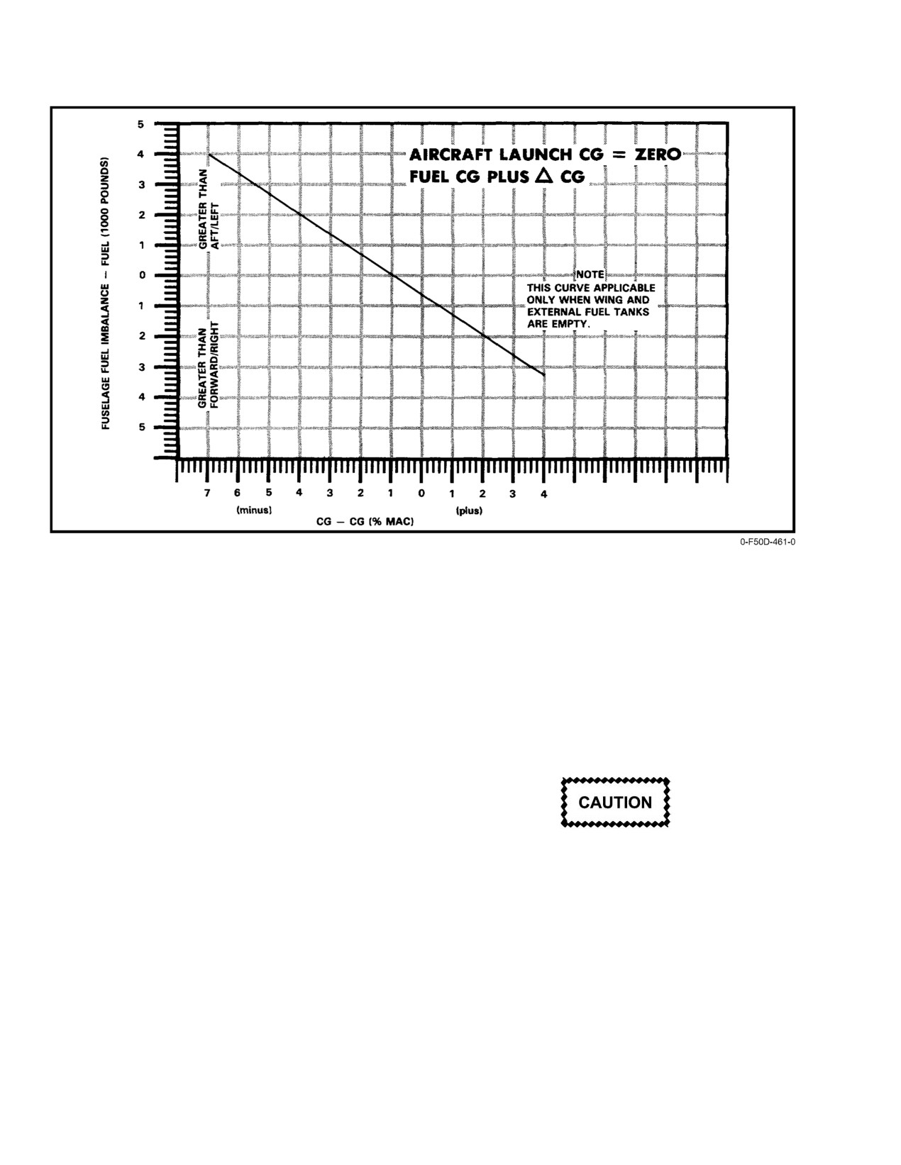
NAVAIR 01−F14AAD−1
Figure 8Ć2.ĄCenter−of−Gravity Variation With Fuel Loading
Aircrew coordination is particularly critical in this
shaking his head from side to side. Never raise the hand into
regime, since the aircrew must ensure that initial flyaway
view or make any motion that might be construed as a salute.
parameters are maintained while remaining alert for any
After the catapult officer observes the pilot’s no−go signal, he
abnormal launch characteristics and engine malfunctions.
will cross his forearms over his head, and then give the
High endspeed and/or single−engine flyaway with trim
standard release tension signal. When the catapult is
settings above 2 degrees may require significant forward
untensioned, the catapult officer will signal the pilot to raise
stick pressure. In all configurations, the use of afterburner
the launch bar. The pilot shall ensure that the throttles are
and/or level rapid acceleration will require reduced nose trim
seated in the catapult detent and will raise the launch bar with
settings. The RIO shall scan a repeat of the pilot’s heads up
the LAUNCH BAR ABORT switch.
display and associated standby flight instruments to ensure
the correct flyaway conditions are met (airspeed, altitude and
attitude).
Additional considerations exist for night/IFR catapult
launches. Aircraft acceleration and the lack of external visual
To avoid damage to the launch bar retract mechaĆ
cues will cause the aircrew to sense that the nose is higher
nism, do not actuate the LAUNCH BAR ABORT
than actual and can result in spatial disorientation. Under
switch with the nosewheel deflected off center.
these conditions, a vigilant instrument scan is required to
ensure that the proper attitude is maintained throughout the
When the launch bar is clear of the shuttle, the catapult
launch and subsequent climbout.
officer will move the shuttle forward of the aircraft launch
bar. At this point the aircraft is no longer in danger of being
8.4.3
Catapult Abort Procedures (Day)
launched. The catapult officer will signal the pilot to lower
If after turnup on the catapult, the pilot determines that
the launch bar and then step in front of the aircraft and signal
the aircraft is down, the pilot gives the no−go signal by
the pilot to throttle back.
ORIGINAL
8−6
NAVAIR 01−F14AAD−1
D If the aircraft is down prior to it being pushed
D The LSO and tower must be informed if the
or pulled back for release from the holdback
landing is to be made in any wing or flap conĆ
fitting and when directed by the catapult offiĆ
figuration other than 20° wing sweep, flaps
cer, the launch bar shall be raised by the
and slats down, or RATS inoperative, to
LAUNCH BAR ABORT switch.
ensure wind−over−deck requirements are met.
D Unkneeling the nosegear while the launch bar
D Do not attempt shipboard landing with
is in the catapult track or shuttle will damage
inoperative ROLL SAS and store asym−
the launch bar linkage and bungees. The pilot
metry greater than
170,000 inch−pounds
should unkneel the aircraft only when he is
because of lateral pilot−induced oscillation
sure that the launch bar is free to rise and
in the approach unless field divert is not
upon signal from the catapult officer or taxi
possible. (Example: weapon rail at station 6
director.
and AIM−54 missile at station
8 equals
170,000 inch−pounds.)
If the aircraft is down after the go signal is given,
transmit the words Suspend, Suspend"; however, the
Note
flightcrew should be prepared for the catapult stroke and to
With the hook down, airspeed in excess of
perform emergency procedures if required.
300 knots may cause the hook transition light to
8.5
LANDING
illuminate.
8.5.1
Carrier Landing Pattern (VFR)
8.5.2
Manual Approach Technique
The VFR carrier landing pattern (Figure 8−3) shall be
The rapid engine response characteristics allow the
in accordance with the CV NATOPS manual. The pattern
pilot to make timely, small amplitude power changes to make
starts with the level break at 800 feet and 300 to 350 knots.
glideslope corrections. Because of the rapid engine response
The break interval will be approximately one−half of the
and high−throttle sensitivity, the pilot must avoid overĆ
desired ramp interval time
(15 to
17 seconds normal
controlling power. DLC should be engaged for all apĆ
interval). When established wings level on the downwind
proaches. Approaches flown without DLC will degrade
leg, descend to and fly the pattern at 600 feet MSL. Engage
flying qualities resulting in significant glideslope and lineup
DLC upon completion of flap extension.
deviations. Pitch compensation for DLC inputs is optimized
for approach airspeeds. Activation of DLC at higher
Note
airspeeds will result in inducing noticeable changes in pitch
Selection of DLC during the flap extension cycle
attitude. DLC may be employed by vernier or bang−bang
can generate excessive pitch rates. DLC is to be
control depending on the extent of the correction required.
selected only upon completion of the flap cycle.
DLC is most effective in correcting for glideslope deviations
DLC must be deselected prior to flap retraction
caused by gusty conditions or ship burble. Caution should be
to avoid excessive pitch trim change with autoĆ
taken not to use DLC to compensate for a major overpowered
matic DLC stowage during the flap retraction
or underpowered condition.
cycle.
Slow to 15 units AOA or computed on−speed (whichĆ
ever is faster) and verify airspeed/AOA correlation, engage
APC if desired, check for proper DLC operation, and
complete the Landing Checklist prior to reaching the 180°
position. The 180° turn is commenced 1 to 1.2 nm abeam the
Caution must be taken to avoid sustained full−
LSO platform to arrive at the 90° position at approximately
down DLC commands for a high condition at the
450 feet MSL. The nominal bank angle throughout the turn
ramp as this will result in excessive sink rates and
should be
25° to
27°. Glideslope meatball acquisition
subsequent hard landings.
will occur at approximately 0.6 nm. Do not descend below
300 feet prior to acquiring the ball. On rollout to final,
slightly overshoot the ship’s wake. Optimum time on
glideslope is approximately 15 to 18 seconds.
8−7
ORIGINAL
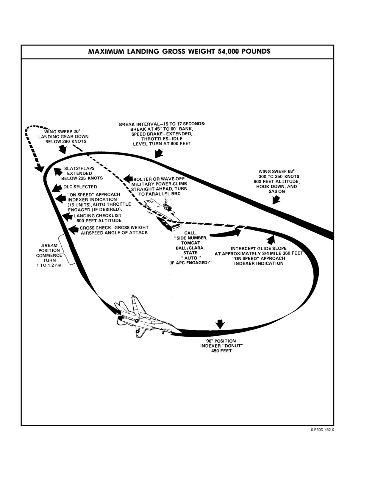
NAVAIR 01−F14AAD−1
Figure 8Ć3.ĄCarrier Landing Pattern
ORIGINAL
8−8
NAVAIR 01−F14AAD−1
Once established on glideslope, keep the scan going,
8.5.4
Waveoff Technique
cross−checking meatball, lineup, and AOA. Be alert for a
A waveoff will be initiated immediately upon a signal
waveoff. With rough seas and pitching decks, some erratic
or voice call from the LSO. MIL power should be used for all
meatball movements may be encountered. If this is the case,
dual−engine waveoffs. Maintain the landing attitude until a
average out the ball movement to maintain smooth and safe
positive rate of climb is established. Do not over rotate the
rate of descent. To avoid being cocked up," arrest a come
aircraft in close as this significantly increases the chance of
down in close" with power and up DLC. Attempts to arrest
in−flight engagement.
high sink rates with nose attitude alone could result in landing
damage to the ventral fins and afterburner. Also, avoid
dropping the nose prior to touchdown as this significantly
increases the chances of a hook skip bolter. Upon touchdown,
add full MIL power, manually retract speedbrakes, and
maintain aft stick pressure to minimize chances of a hook
Dual engine afterburner waveoffs are prohibited.
Inadvertent arrestment or in−flight engagement
skip bolter. Selection of MIL power will automatically
disengage DLC and retract the speedbrake.
in dual afterburner would result in catastrophic
damage to the aircraft and/or arresting gear.
A good start is imperative to minimizing lineup
corrections while on the glideslope and will prevent the
Normally, waveoffs will be taken straight ahead,
especially when close in. When using APC, waveoff
tendency to chase lineup. Small, coordinated rudder inputs
should be used to reduce the nose yaw that is easily generated
technique is the same as for manual approaches except that
a force of approximately 8 pounds is required to disengage
by lateral stick inputs.
the throttle torque switches. Disengagement of the APC by
8.5.3
Approach Power Compensator Technique
overriding the throttle forces results in the throttle MODE
switch automatically returning to BOOST and illuminates
Practice is required to develop the proper control habits
the AUTO THROT light on the pilot left−hand ladder light
necessary to use the APC. For the APC to perform
assembly. A time delay relay holds the AUTO THROT light
satisfactorily, smooth attitude control is essential. Large,
on for 10 seconds following APC disengagement.
abrupt attitude changes result in excessive power changes.
APC use is not recommended in gusty conditions. The APC
will overcontrol AOA fluctuations resulting in large airspeed
and/or glideslope deviations. The APC system was designed
to be used with the engines operating in the primary mode and
is not recommended with either one or both of the engines in
If a force in excess of 14 pounds is applied to
secondary mode.
break the throttles out of the automatic mode, the
throttle MODE switch will return to BOOST but
As the initial turn from the 180° position is made,
the throttle mode will revert to manual. The
the aircraft will momentarily indicate up to 2 units slow. The
switch must be cycled to MAN and back to
APC will adjust power to correct back to onspeed condition
BOOST to regain the BOOST mode.
throughout the remainder of the turn. Upon rollout on
glideslope, the pilot must override the tendency for the nose
8.5.5
Bolter Technique
to pitch up by maintaining slight forward stick. The aircraft
The bolter maneuver is effected by selecting MIL and
will indicate 1 to 2 units fast, which will slow to onspeed
slight aft control stick until the desired flyaway attitude is
within 5 seconds. The use of DLC in conjunction with small
established.
attitude changes to maintain glideslope will minimize AOA
deviations and result in optimal APC performance. Timely
use of DLC can also be used to more rapidly correct from a
fast or slow condition. Close−in corrections are very critical.
If a high in−close situation develops, the recommended
procedure is to stop the meatball motion and not attempt to
The use of excessive backstick on a bolter may
recenter it. A low in−close condition is difficult to correct
cause the tail surface to stall, delaying aircraft
with APC and often results in an over−the−top bolter. It may
rotation and causing the aircraft to settle off the
be necessary to disengage or manually override APC in order
angle.
to safely recover from a low in−close situation. Throughout
8.5.6
Bingo Fuel
the approach, the pilot should keep his hand on the throttles
in the event APC disengages inadvertently. A smooth throttle
Fuel reserves should be programmed depending on
transition from AUTO to BOOST mode can be achieved
distance of the field from the CV, aircraft configuration, and
by depressing the CAGE/SEAM button on the inboard
en route weather. This bingo fuel quantity should be set
throttle grip.
before takeoff.
8−9
ORIGINAL
NAVAIR 01−F14AAD−1
8.5.7
Arrested Landing and Exit From the
2. Accomplish final changes to radio and IFF upon
Landing Area
departing marshal or earlier. After these changes are
made, the pilot should make no further changes
As the aircraft touches down, advance throttles to MIL.
except under emergency conditions.
Upon completion of landing rollout, reduce power to IDLE.
Raise the hook and flaps and select wing−sweep BOMB while
3. When commencing penetration, initiate a standard
allowing the aircraft to roll aft. Apply brakes on signal. Flaps
descent:
250 knots,
4,000 fpm, speedbrakes as
retraction requires approximately 7 seconds. When the flaps
required.
are fully retracted the wings will sweep aft. Engage
nosewheel steering and taxi forward on the come−ahead
signal. If the wings sweep aft to 55_, auxiliary and main flap
retraction has been verified and full−aft wing sweep may be
selected using the emergency handle. The RIO should
If a gear and/or flaps down penetration is reĆ
monitor wing−sweep position while taxiing. Oversweep
quired, ensure that the wings are programmed
should be selected prior to final spot and shutdown. The
forward of 22° prior to lowering flaps. If flaps are
engines should remain running until the cut signal is given by
lowered with wings swept aft of 22_, auxiliary
the plane director. If at any time during this phase of
flap extension will be inhibited resulting in rapid
operations a brake failure occurs, pull the parking brake. If
nosedown pitch rates.
the aircraft continues to roll, drop the hook, advise the tower,
4. Radar and barometric altimeters shall be cross−
and signal for chocks to be installed. Use nosewheel steering
checked continuously when below 5,000 feet.
to ensure that the aircraft remains on the deck. Do not
unstrap, dearm the ejection seat, or leave the cockpit until
8.5.10
Platform
tiedowns have been installed.
At 20 miles passing through 5,000 feet, aircraft descent
Note
shall be slowed to 2,000 fpm. At this point, a mandatory,
unacknowledged voice report will be broadcast by each pilot.
Aircrew shall inform tower in the event of RATS
The aircraft side number will be given and platform" will be
failure on landing.
reported. Continue descent to 1,200 feet.
8.5.8
Carrier−Controlled Approaches
8.5.11
Ten−Mile DME Fix
Should these procedures conflict with the applicable
CV Air Operations manual, the latter shall govern. Detailed
1. Commence transition to landing configuration,
pilot−controller voice procedures must be established in
unless otherwise directed by CCA, maintaining
accordance with each ship’s CCA doctrine. Figure 8Ć4 shows
1,200 feet.
a typical carrier−controlled approach. Mode I, mode IA, and
2. Gear and flaps shall be down by 8 miles.
mode II ACLS approaches are described in Chapter 17,
Automatic Carrier Landing System. Aircrew should have a
3. Complete the landing checklist. Check anti−ice,
thorough understanding of this chapter and the DFCS and
lights, and rain removal, as required.
APC portions of Chapter 2 prior to attempting a coupled
ACLS approach.
8.5.12
Six−Mile DME Fix
8.5.9
Hold Phase
For a precision radar approach, maintain 1,200 feet
at approach speed until intercepting the glidepath at 3 to
Five minutes before penetration, defogging shall be
3.25 miles, unless otherwise directed.
actuated and maximum comfortable interior temperature
will be maintained to prevent possible fogging or icing on the
For an air surveillance radar approach, a gradual
windshield and canopy.
descent of 600 fpm can be commenced departing the 6−mile
DME fix. Maintain 600 feet until the aircraft intercepts the
Note
center of the glideslope at 1¼ to 1½ miles on a 3.5° slope.
Commence a descent of 500 to 700 fpm, using the following
Fuel dump is accomplished by gravity flow and
checkpoints:
its effectiveness is reduced during the peneĆ
tration descent. Fuel dump, if required, should be
1. 1 mile 460 feet.
planned accordingly for the level leg.
2. ¾ mile 360 feet.
1. Before descent, check shoulder harness handle
3. ½ mile 260 feet.
locked, set lights as directed by existing weather,
and lower arresting hook.
ORIGINAL
8−10
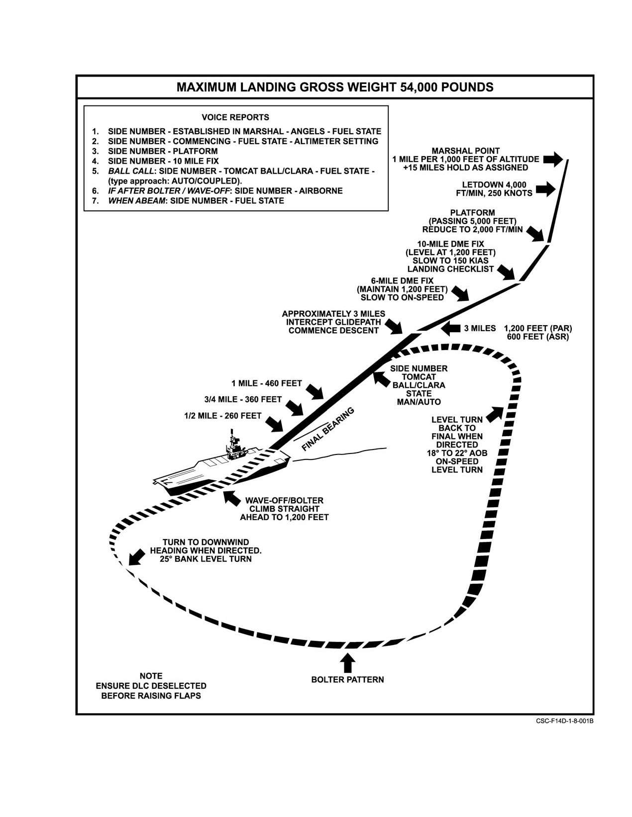
NAVAIR 01−F14AAD−1
Figure 8Ć4.ĄCarrier−Controlled Approach (Typical)
8−11
ORIGINAL
NAVAIR 01−F14AAD−1
8.5.13
Meatball Contact
8.7
NIGHT FLYING
When transitioning to a visual approach (at approxiĆ
Night carrier operations will have a much slower
mately ¾ of a mile), make a report call with the following
tempo than daylight operations and it is the pilot’s responsiĆ
information: side number, TOMCAT, meatball or Clara (no
bility to maintain this tempo. Normal day carrier operations
meatball), fuel state, and type pass. The LSO will acknowlĆ
shall be used except as modified below.
edge, and instructions from the final controller will cease.
8.7.1
Briefing
Pilots are cautioned against premature contact reports and
transition to visual glideslope during night recoveries when
Before initial night flight operations, all pilots should
visibility permits sighting the ship beyond 2 to 3 miles. The
receive an additional briefing from the following persons:
height and dimension of the entire lens or mirror optical beam
1. Flight deck officer
at 1¼ miles is over 200 feet and the true center cannot be
distinguished. This, coupled with the relatively short length
2. Catapult officer
of the runway lights, will give the pilot the illusion of being
3. Arresting gear officer
high when, in fact, the aircraft may be well below optimum
glideslope. An additional advantage of delaying the meatball
4. LSO
report
(even though the ball is in sight) is that the final
5. CATCC.
controller will continue lineup instructions that can greatly
assist the pilot in establishing satisfactory lineup. Use the
Individual flight briefings will include all applicable
vertical velocity indicator to set up a rate of descent of 500
items outlined above, with particular emphasis on weather
to 700 fpm. The AN/ARA−63 instrument landing system
and bingo fuel.
(ILS) is an excellent aid during the approach and should be
8.7.2
Preflight
used whenever possible. ILS glideslope azimuth and elevaĆ
tion signals are provided as command fly to" indications and
In addition to normal cockpit preflight, ensure that
are displayed via the VDI and/or the HUD in the TLN mode.
external light switches are properly positioned for poststart
8.6
WAVEOFF AND BOLTER
light check. Install night filters on applicable cockpit
displays.
In the event of a waveoff or bolter, climb straight ahead
8.7.3
Poststart
to 1,200 feet and maintain 150 knots. When directed by CCA,
initiate a level turn to the downwind leg reporting abeam with
Adjust cockpit light to desired brightness. When ready
fuel state. (If no instructions are received within 2 minutes or
for taxi, indicate with appropriate signal.
4 miles DME, attempt radio contact; if unable, assume
communications failure and initiate the downwind turn to the
8.7.4
Taxi
reciprocal of final bearing reporting abeam with fuel state.
Night deck−handling operations are of necessity slower
If no acknowledgment is received, start a turn at 4 miles
than those used during the day. When a doubt arises as to the
or 2 minutes to intercept final bearing.) A 20° bank angle at
meaning of a signal from a taxi director, stop.
150 knots on the upwind turn establishes the aircraft at the
desired 2 miles abeam on the downwind leg.
8.7.5
Catapult Hookup (Night)
CATCC clears the aircraft to turn inbound to intercept
Procedures for aircraft catapult hookup at night are
final bearing. A level, on−speed approach turn of 18° to 22°
identical to those used during day operations. However, it is
bank angle from the normal downwind position allows the
difficult to determine your speed or degree of motion over
aircraft to properly intercept final bearings at a minimum of
the deck. The pilot must rely upon, and follow closely, the
3 miles aft of the ship. Traffic spacing ahead may require that
plane director’s signals.
the aircraft continue on downwind leg well past the normal
8.7.6
Catapult Launch
abeam position before being directed to turn to final bearing.
No attempt should be made to establish visual contact with
On turnup signal from the catapult officer ensure
the ship when executing a CCA until the final approach turn
throttles in MIL and check all instruments. When ready for
has been executed.
launch, place external light master switch ON (bright and
steady). After launch, establish an 8° to 10_ pitch attitude,
Note
cross−checking instruments to ensure a positive rate of climb.
The radar beacon
(AN/APN−154) should be
Retract the landing gear. An altitude of 500 feet is considered
turned off as soon as practicable after landing to
to be minimum altitude for retraction of flaps.
avoid causing interference with AN/SPN−42
control of other aircraft in the pattern.
ORIGINAL
8−12
NAVAIR 01−F14AAD−1
When well established in a climb, switch lights to flashing or
as applicable for an instrument climbout. The standby
indicator should be used in the event of a primary display(s)
malfunction.
If the aircraft is down after the go signal is given,
transmit the words Suspend, Suspend"; howĆ
ever, the flightcrew should be prepared for
the catapult stroke and to perform emergency
procedures if required.
If wings sweep back inadvertently, close attenĆ
tion should be paid to maintaining positive rates
of climb. The loss of lift incurred by premature
wing sweep aft can result in significantly deĆ
creased rates of climb, with very little change in
pitch attitude and trim requirements.
D If the aircraft is down prior to it being pushed
8.7.7
Catapult Abort Procedures (Night)
or pulled back for release from the holdback
fitting and when directed by the catapult
The pilot no−go signal for night launches will be to not
launching officer, the launch bar shall be
turn on the exterior lights, and to transmit on the land/launch
raised by the LAUNCH BAR ABORT switch.
frequency the aircraft side number, the catapult the aircraft
is on, and the words Suspend, Suspend." After the catapult
D Unkneeling the nosegear while the launch bar
is untensioned, the catapult officer will signal to raise the
is in the catapult track or shuttle will damage
launch bar. The pilot shall ensure that the throttles are seated
the launch bar linkage and bungees. The pilot
in the catapult detent or throttle friction is full forward before
should unkneel the aircraft only when sure
raising the launch bar with the LAUNCH BAR ABORT
that the launch bar is free to rise and upon sigĆ
switch. When the launch bar is clear of the shuttle, the
nal from the catapult officer or taxi director.
catapult officer will move the shuttle forward of the aircraft
8.7.8
Arrested Landing and Exit From
launch bar. At this point the aircraft is no longer in danger of
Landing Area (Night)
being launched. The catapult officer will signal the pilot to
lower the launch bar and then step in front of the aircraft and
During approach, all lights shall be on bright and
signal the pilot to throttle back.
steady. At the end of arrestment rollout, turn off external
lights and follow the director’s signals while effecting the
normal aircraft cleanup procedures.
8−13 (Reverse Blank)
ORIGINAL
NAVAIR 01−F14AAD−1
CHAPTER 9
Special Procedures
9.1
IN−FLIGHT REFUELING PROCEDURES
5. REFUEL PROBE switch As Desired (transition
light OFF).
Note
6. Wing−sweep switch MAN/wing−sweep angle
Before commencing in−flight refueling operaĆ
As Desired.
tions, each flight crewmember shall become
familiar with the NATOPS Air Refueling Manual,
7. Visors Recommended Down.
NAVAIR 00−80T−110, and in−flight refueling sysĆ
tem description.
9.1.1
In−Flight Refueling Controls
Regardless of fuel management panel switch positionĆ
To prevent fuel fumes from entering the cockpit
ing, at low fuel states the initial resupply of fuel is discharged
through the environmental control system (ECS)
into the left− and right−wing box tanks. Thereafter distribuĆ
because of possible fuel spills during in−flight reĆ
tion of the fuel to the forward, aft, wing, and external tanks
fueling, select AIR SOURCE pushbutton L ENG.
is controlled by the WING/EXT TRANS switch position.
The split refueling system to the left and right engine feed
9.1.3
In−Flight Refueling Techniques
group provides for a relatively balanced center of gravity
Note
condition during refueling. Selective refueling of the fuseĆ
lage or all fuel tanks is provided on the REFUEL PROBE
The following procedures, as applied to tanker
switch with the probe extended. In the FUS/EXTD position,
operation, refer to single−drogue tanker only.
normal fuel transfer and feed is unaltered. This position is
used for practice plugins, fuselage only refueling, or return
Refueling altitudes and airspeeds are dictated by
flight with a damaged air−refueling probe. The ALL/EXTD
receiver and/or tanker characteristics and operational needs,
shuts off wing and external tank transfer to permit the
consistent with the tanker’s performance and refueling capaĆ
refueling of all tanks. The REFUELING PROBE switch
bilities. This covers a practical spectrum from the deck to
circuit uses essential dc No. 2 power to control operation of
35,000 feet, 170 to 300 knots, and wing−sweep angles of
the probe actuator through redundant−extend solenoids and
20° to 68°. Optimum airspeed and wing−sweep position is
a single−retract solenoid.
240 knots and approximately 40° wing−sweep. This configuĆ
ration increases aircraft angle of attack enough to lower the
9.1.2
In−Flight Refueling Checklist
receiver’s vertical tails below the tanker’s jetwash and
decreases bow wave effect. SAS−off tanking can most easily
The in−flight refueling checklist shall be completed
be performed at 200 KCAS with 40° of wing−sweep.
before plug−in.
9.1.3.1
Approach
1. RDR switch STBY.
Once cleared to commence an approach and with refuelĆ
2. Arming switches SAFE.
ing checklists completed, assume a position 5 to 10 feet in trail
of the drogue with the refueling probe in line in both the horiĆ
3. DUMP switch OFF.
zontal and vertical reference planes. Trim the aircraft in this
4. AIR SOURCE pushbutton L ENG.
9−1
ORIGINAL
NAVAIR 01−F14AAD−1
stabilized approach position and ensure that the tanker’s
evident in the refueling hose. The tanker’s drogue and hose
(amber) ready light is illuminated before attempting an
must be pushed forward 3 to 5 feet by the receiver probe
approach. Select a reference point on the tanker as a primary
before fuel transfer can be effected. This advanced position
alignment guide during the approach phase; secondarily, rely
is evident by the tanker’s amber ready light going out and the
on peripheral vision of the drogue and hose and supplementaĆ
green fuel transfer light coming on. While plugged in, merely
ry remarks by the RIO. Increase power to establish an
fly a close tail−chase formation on the tanker. Although this
optimum 3 to 5−knot closure rate on the drogue. It must be
tucked−in condition restricts the tanker’s maneuverability,
emphasized that an excessive closure rate will cause a violent
gradual changes involving heading, altitude, and/or airspeed
hose whip following contact and/or will increase the danger
may be made. The precise flying imposed on both the tanker
of structural damage to the aircraft; too slow a closure rate
and receiver pilots requires a lot of heads down" time, yet
results in the pilot fencing with the drogue as it oscillates in
a sharp lookout doctrine must be maintained. This is the
close proximity to the aircraft nose. During the final phase of
receiver RIO’s primary responsibility.
the approach, the drogue has a tendency to move slightly
upward and to the right as it passes the nose of the receiver
9.1.3.4
Disengagement
aircraft because of the aircraft−drogue airstream interaction.
Disengagement from a successful contact is accomĆ
Small corrections in the approach phase are acceptable.
plished by reducing power and backing out at a 3 to 5−knot
However, if alignment is off in the final phase, it is best to
separation rate. Care should be taken to maintain the same
immediately return to the initial approach position and
relative alignment on the tanker as upon engagement. The
commence another approach, compensating for previous
receiver probe will separate from the drogue coupling when
misalignments by adjusting the reference point selected on
the hose reaches full extension.
the tanker. Small lateral corrections with a shoulder probe"
are made with the rudder, and vertical corrections with the
When clear of the drogue:
horizontal stabilizer. Avoid any corrections about the
1. REFUEL PROBE switch RET.
longitudinal axis since they cause probe displacement in both
the lateral and vertical reference planes.
2. Probe transition light Check Out.
3. AIR SOURCE pushbutton BOTH ENG.
9.1.3.2
Missed Approach
4. Wing−sweep switch AUTO.
If the receiver probe passes forward of the drogue
basket without making contact, a missed approach should be
Resume normal flight operations.
initiated immediately. Also, if the probe impinges on the
canopy−lined rim of the basket and tips it, a missed approach
9.2
FORMATION FLIGHT
should be initiated. Realization of this situation can be
The following formation descriptions are recomĆ
readily ascertained through the RIO. A missed approach is
mended guidelines for F−14 multiplane positioning.
executed by reducing power and backing to the rear at an
opening rate commensurate with the optimum 3 to 5−knot
closure rate made on an approach. By continuing an approach
past the basket, a pilot might hook the probe over the hose
and/or permit the drogue to contact the receiver aircraft
fuselage. Either of the two aforementioned hazards require
Parade formation IFR/VFR and loose cruise
more skill to calmly unravel the hose and drogue without
flight shall not be performed with the flight lead
causing further damage than to make another approach. If the
utilizing autopilot ground−track destination
initial approach position is correctly in line with the drogue,
steering because of the midair collision potential
the chance of hooking the hose is diminished as the need for
associated with inadvertent way−point steering
last−minute corrections is minimized. After executing a
selection and rapid aircraft AOB changes.
missed approach, analyze previous misalignment problems
and apply positive corrections to preclude a hazardous
9.2.1
Parade Formation
tendency to blindly stab at the drogue.
The basic parade position is either left or right echelon,
9.1.3.3
Contact
or a combination of both, as in fingertip three−plane
formation. The parade formation is used primarily for
When the receiver probe engages the basket, it will seat
multiplane maneuvering at night, in IMC, or during entry into
itself into the drogue coupling and a slight ripple will be
or exit from an airport traffic area.
ORIGINAL
9−2
NAVAIR 01−F14AAD−1
Wing sweep: 20_
2. Wingtip separation is determined by a position on
Configuration: Clean or dirty.
the bearing line where the trailing edges of the lead
aircraft’s ventral fins are aligned. At this position,
1. Line of bearing is determined by placing the upper
the trailing edge of the exhaust nozzles should apĆ
leading edge of the lead aircraft’s intake on the exĆ
pear in line to the RIO.
plosive seat warning triangle below the RIO cockpit.
3. Stepdown is determined by allowing approximately
2. Wingtip separation is determined by a position on
6 inches of the lead’s opposite engine nacelle to
the bearing line where the leading edges of the lead
show below the near engine nacelle.
aircraft’s ventral fins are aligned.
This position should provide the wingman with
approximately 12 feet of wingtip separation and 12 feet of
3. Stepdown is determined by aligning the lead’s
stepdown.
opposite engine nacelle just under the near engine
nacelle.
Slot (dash−4)
This positioning should provide the wingman with
1. Line of bearing is determined by lining up on the
approximately 5 feet of wingtip separation and 10 feet of
lead aircraft’s centerline.
stepdown.
2. Approximately
20 feet of nose−to−tail separation
9.2.2
Break Formation
can be established by placing the wingman’s canopy
bow on the lead aircraft’s exhaust nozzles.
The basic break formation is either left or right
3. Approximately 25 feet of stepdown should be used.
echelon, or a combination of both as in a fingertip three−plane
This position may be cross−referenced by placing
formation. This formation is used primarily for multiplane
entry into the overhead break pattern.
the upper leading edge of dash−2’s or dash−3’s
intake on the pilot’s helmet.
Wing sweep: 68°
Configuration: Clean.
9.2.4
Cruise Formation
1. Line of bearing is determined by placing the upper
Cruise is the basic formation used for multiplane transit
leading edge of the lead aircraft’s intake on the exĆ
to or from an operating area where increased maneuverĆ
plosive seat warning triangle below the RIO cockpit.
ability is desired.
2. Wingtip separation is determined by a position on
Wing sweep: 20°
the bearing line where approximately 1 foot of the
Configuration: Clean.
forward edge of the lead’s opposite ventral fin
shows in front of the near ventral fin.
1. Line of bearing is determined by placing the upper
leading edge of the lead aircraft’s intake on the
3. Stepdown is determined by aligning the lead’s
RIO’s canopy bow.
opposite engine nacelle just under the near engine
nacelle.
2. A second line of bearing is determined by placing
the lead aircraft’s wingtip light on the forward upper
This position should provide the wingman with
UHF antenna.
approximately 15 feet of wingtip separation and 10 feet of
stepdown.
3. Wingtip separation is determined by allowing
approximately 1 foot of the lead’s opposite exhaust
9.2.3
Diamond Four−Plane Formation
nozzle to show behind the near exhaust nozzle.
The diamond is the basic four−plane formation used for
This position should provide the wingman with
entry into the overhead break or for aerial fly−bys.
approximately 64 feet of wingtip separation and 10 feet of
nose−to−tail separation.
Wing sweep: 68_
Configuration: Clean.
Right and left echelon (dash−2 and dash−3, respectively)
1. Line of bearing is determined by placing the upper
leading edge of the lead aircraft’s intake on the
pilot’s helmet.
9−3
ORIGINAL
NAVAIR 01−F14AAD−1
9.2.5
Aircraft Lighting During Night
deck personnel. Tow aircraft holds this position
Formation Flight
until released by catapult director.
The lead aircraft anticollision lights will normally be
2.
When signaled to do so, banner crew lays banner on
off during night formation flight in parade. However the
flight deck
45 feet starboard of waist catapult
possibility exists that the wing aircraft can inadvertently
centerline and 10 feet aft of unit horizontal stabilaĆ
stray into a position aft of the normal bearing where only a
tor, with banner bar perpendicular to the catapult
single white tail light on lead is visible. In this position,
centerline.
serious misjudgment of separation and closure rate can occur.
To prevent this, lead aircraft anticollision lights should be on
3.
Banner crew sequentially positions nylon towline
when the wing aircraft is not in normal parade and mission
bundle lengthwise and parallel to catapult track in
requirements permit.
position in front of banner. Nylon towline, with preĆ
pared end facing banner buckle, is attached to banĆ
9.3
BANNER TOWING
ner using swivel and connecting link. Steel cable
leader (75 feet of 3/16−inch diameter) is attached to
9.3.1
Ground Procedures
forward end of nylon towline bundle using connectĆ
The following procedures are provided for guidance.
ing link.
Local course rules may dictate modification of these steps:
4.
Banner crew then unrolls leader forward, down
1.
When tower clearance onto the duty runway has
angle deck and parallel to catapult track to prevent
been received, tow aircraft taxis to position as diĆ
entanglement and kinks. The forward end of leader
rected by tow hookup crew. Tow aircraft holds this
is brought back and laid on deck near the aircraft’s
position until released by tow hookup crew. Escort
right main landing gear. Forward end of leader has
aircraft maintains position on taxiway at approach
Mk 8 Mod 0 target release ring attached to it.
end of runway.
5.
Upon clearance from catapult officer, banner crewĆ
2.
When signaled to do so by tow hookup crew, tow airĆ
member crawls underneath aircraft with leader in
craft proceeds to taxi down runway.
hand, just aft of right ventral fin, and attaches Mk 8
3.
Upon receipt of visual taxi signal from tow hookup
Mod 0 target release ring to banner tow adapter.
crew to slow down, escort aircraft relays this signal
Upon appropriate signals from the flight deck direcĆ
to tow aircraft via UHF radio.
tor, the pilot lowers hook to assure proper detachĆ
ment of target release ring and then raises the hook.
4.
Upon receipt of visual taxi signal from tow hookup
The banner crewmember will then reattach target
crew to stop, escort aircraft relays this signal to tow
release ring.
aircraft via UHF radio.
5.
Upon receipt of signal from tow hookup crew that
6.
After hookup, the banner crewmember exits from
tow hookup is complete, escort aircraft requests tow
beneath aircraft at same place he entered. He then
aircraft to take up slack.
walks toward island and gives thumbs up signal to
catapult officer. The banner, towline, and leader are
6.
Tow aircraft proceeds to taxi down the runway.
now ready for launch.
7.
When banner moves forward onto runway, escort
9.3.3
Flight Procedures
aircraft transmits, Tow aircraft hold, good banner,"
and taxis onto runway abeam banner for takeoff.
Flight tests have demonstrated no significant degradaĆ
tion of aircraft performance and handling characteristics
8.
When ready, tow aircraft transmits, Tower, Lizard
when towing a banner.
616 for banner takeoff, escort to follow banner."
9.
After banner becomes airborne, escort aircraft comĆ
mences takeoff roll.
9.3.2
Shipboard Procedures
Angle of bank should be limited to 30_ or less to
preclude contact between the tow cable and
The following procedures are provided for guidance.
afterburner nozzle.
Local rules may dictate modification of these steps:
1. When clearance has been received, tow aircraft taxĆ
is to the catapult shuttle in use as directed by flight
ORIGINAL
9−4
NAVAIR 01−F14AAD−1
Note
9.3.3.2
Cruise/Pattern
Depending on the airspeed of the tow aircraft, the
No special pilot techniques are required when towing
banner will normally hang 200 to 400 feet below
a banner. En route cruising speeds of 180 to 220 KIAS will
the tow aircraft’s altitude.
provide adequate energy for mild maneuvering while
minimizing banner fray. If a low−pattern airspeed is desired,
Refer to Chapter 4 for banner towing restrictions.
extend flaps/slats if necessary to maintain AOA at or below
9.3.3.1
Takeoff
12 units. The tow aircraft must call all turns to allow the chase
aircraft to position itself on the outside of the turn.
Normal takeoff procedures, including rotation speeds
and techniques, are suitable for takeoff with the banner.
If the banner is shot off or falls off in flight, the
remaining cable should be dropped in the gunnery area or in
D Takeoff ground roll with banner can be estiĆ
a confirmed clear area. After the cable is released, a chase
mated by adding a factor of 10 percent to basic
aircraft should join to verify that the cable has been dropped.
aircraft takeoff performance. If aircraft lift−
off will not occur prior to crossing the long−
field arresting gear, the gear must be removed
to preclude the banner being torn off.
D If the crosswind component is in excess of
Without the banner, any remaining cable will
10 knots, the takeoff roll should be made on
the upwind side of the runway to prevent the
flail unpredictably. The chase should approach
the tow aircraft from abeam, avoiding a cone−
banner from striking the runway lights on
the downwind side of the runway.
shaped area defined by the tow’s 4− to 8−o’clock
positions.
Note
9.3.3.3
Descent
Adequate clearance exists to prevent contact beĆ
Airspeeds of 160 to 220 KIAS should be used for
tween the tow cable and speedbrakes during
descent. Flaps and slats may be utilized to increase the rate
ground operation. If takeoff is aborted, basic
of descent as desired.
emergency procedures are applicable. The tow
cable will be released when the tailhook is
lowered.
After lift−off, continue rotation to 15° (maximum of
20_), while raising the landing gear. Do not exceed 17 units
AOA. Climb out at 180 to 200 KIAS until the flaps are up,
Speedbrakes should not be used while towing
then continue climb at 200 to 220 KIAS.
since limited clearance exists between the cable
and speedbrakes during extension and retraction
Note
in flight.
D Avoid use of afterburner to prevent damage to
9.3.3.4
Banner Drop
tow cable.
The tow aircraft should extend its flaps and reduce
D Tow airspeeds in excess of 220 KIAS will reĆ
airspeed (140 to 160 KIAS, 12 units AOA maximum) for the
sult in excessive banner fraying.
drop. The banner should be dropped in wings−level flight at
a minimum aircraft altitude of 1,000 feet AGL. The chase
For shipboard operations, after lift−off, rotate to 15°
aircraft should ensure adequate clearance exists between the
(20° maximum) not to exceed 17 units AOA while raising
banner and ground obstacles during approach to the drop
the gear and flaps. Prior clearance must be received from the
zone and provide calls to assist in lineup. Release is normally
tower for an unrestricted climb. Maintain heading until the
called by the tower when the banner is over the center of the
banner is well clear of ship. Climb out at 180 to 200 KIAS until
drop zone. Release is accomplished by lowering the tailhook.
flaps are up, then continue to climb out at 200 to 220 KIAS.
In most cases, the banner will hit down range of the release
point. However high−wind conditions may require the tow
Note
aircraft to adjust the release point to avoid downwind travel
The maximum aircraft gross weight for a shipĆ
of the banner. Following banner release, the tailhook should
board banner launch is 67,000 pounds.
be raised.
9−5
ORIGINAL
NAVAIR 01−F14AAD−1
9.3.3.5
Shipboard Banner Drop
Have escort pilot confirm that banner breaks off on
ground collision, and determine length of remaining
The tow aircraft should extend its flaps and reduce
tow cable.
airspeed (140 to 160 KIAS, 12 units AOA maximum) for the
drop. The banner should be dropped in a clear area in
wings−level flight at a minimum altitude of 1,000 feet MSL.
If a clear area is not available, the banner should be dropped
approximately
1 nm abeam the port side of the carrier.
Release is called by the air officer when the banner is over
The escort pilot must remain well clear of
the drop zone. Banner release is accomplished by lowering
the remaining cable. The last 25 percent of the
the tailhook.
remaining cable will flail unpredictably.
2.
If 100 feet or greater of remaining tow cable length is
confirmed by escort pilot, plan to touch down 1,000 to
1,500 feet long, runway length permitting.
When the tailhook is lowered for banner release,
ensure that the balance ball is centered or slightly
right (left yaw). If any right yaw is present, tow
cable/tailhook entanglement is possible.
Every effort must be made by the tow pilot not to
9.3.3.6
Banner Release Failure
drag the remaining tow cable across lines,
fences, or other obstacles because of property
If the arresting hook fails to extend, the banner cannot
damage that will result.
be released. In this case, the following procedure is
recommended:
Note
1. In gunnery range (or other cleared area) descend to
The long touchdown should be carefully planned
low altitude, extend flaps, slow to 140 to 160 KIAS,
because long−field arrestment is impossible.
12 units AOA maximum and descend to 100 to 200 feet
AGL. This will drag banner off on ground (or water).
ORIGINAL
9−6
NAVAIR 01−F14AAD−1
9.4
FUEL MANAGEMENT SYSTEM OPERATIONAL CHECK
The following fuel management system operational check can be used by flightcrews to perform a check of the fuel
transfer system, including FUEL FEED switch, WING/EXT TRANS switch, sump tank interconnect valve, fuselage motive
flow isolation valves, low−level thermistors, and box−beam vent valves. In addition, the procedure tests for proper functioning
of the automatic electrical controls in the fuel feed system. The final four procedures (steps 5 through 8) can best be performed
in a shore−based environment where minimum fuel on deck requirements are not as restrictive.
PROCEDURES
COMMENTS
Initial conditions:
Ensure 4,500 pounds on tapes for operation of
FEED switch.
FWD/R & AFT/L 3,000 pounds (approximately)
L & R FEED 1,500 to 1,750 pounds (full)
L/R WINGS Empty (0 to 200 pounds)
TOTAL 6,000 pounds (approximately)
1.
WING/EXT TRANS switch OFF.
1.
Switch should not move until automatic inter−
connect occurs. Verifies proper automatic electrical
operation.
2.
FUEL FEED switch FWD/R
2.
Verifies sump tank interconnect valve open via
Monitor 500−pound split, AFT/L high.
manual operation and aft fuselage motive flow
valve shut off.
3.
FUEL FEED switch AFT/L
3.
Same as step 2 except forward fuselage motive
Monitor 500−pound split, FWD/R high.
flow valve shut off.
4.
FUEL FEED switch NORM
4.
Verifies system returns to isolated mode with
Verify FWD/R high split remains constant.
no leaks.
5.
Monitor WING/EXT TRANS switch returns to AUTO.
5.
Verifies cell No. 2 or 5 low−level thermistor’s proper
AFT/L 1,700 ± 200 pounds, or
operation to trigger automatic interconnect function.
FWD/R 2,100 ± 200 pounds.
6.
Monitor tapes/feeds for system balancing.
6.
Verifies sump tank interconnect valve opens via
automatic operation and L/R box−beam vent
Note
valves open. Verifies proper operation of
Balancing normally begins 6 to 9 minutes
FWD/AFT motive systems.
after WING/EXT TRANS switch returns to
AUTO.
7.
After landing, run both engines with matched throttles
7.
Verifies proper operation of cell Nos. 2 and 5,
until R and L FUEL LOW lights Illuminate. Verify:
and left box−beam and right box−beam
low−level thermistors.
R FUEL LOW at L FEED 1,000 ± 200 pounds,
L FUEL LOW at R FEED 1,000 ± 200 pounds.
8.
Shut down left engine and pull L FUEL SHUTOFF
8.
Verifies sump tank interconnect valve remains
handle. Continue to run right engine to verify continued
open via right side motive flow pressure.
L FEED quantity decrease. Then shut down right
This verifies proper operation of motive flow
engine.
isolation valve.
9−7 (Reverse Blank)
CHANGE 1
NAVAIR 01−F14AAD−1
CHAPTER 10
Functional Checkflight Procedures
10.1 FUNCTIONAL CHECKFLIGHTS
Functional checkflights will be performed when
directed by, and in accordance with, OPNAVINST 4790.2
series and the directions of NAVAIRSYSCOM type comĆ
manders, or other appropriate authority. Functional checkĆ
flight requirements and applicable minimums are described
below. Functional checkflight checklists are promulgated
separately.
10.2 CHECKFLIGHT PROCEDURES
A flight profile has been established for each checkĆ
flight condition and is identified by the letter corresponding
to the purpose for which the checkflight is being flown (A,
B, C, as shown in Figure 10−1). The applicable letter identifyĆ
ing the profile precedes each item in the functional checkĆ
flight checklist
(NAVAIR 01−F14AAD−1F). PostmainteĆ
nance checkflight procedures are specific and are to be
performed in conjunction with normal NATOPS operating
procedures (Part III). Checkflight personnel shall familiarize
themselves with the profile requirements before each flight.
A daily inspection is required before each checkflight. An
aircraft is considered high gross weight for profile purposes
if over 56,000 pounds total weight. Aircrew shall be cogniĆ
zant of the aircraft’s configuration and the cumulative negaĆ
tive effects of weapons rails and external stores on aircraft
stability.
Figure 10Ć1.ĄFlight Profile
Note
valuable service to the maintenance department by carrying
Shipboard constraints can preclude completion
out this function. The quality of service provided by check
of some items on the applicable flight profile
crews reflects directly in the quality of maintenance and
checklist.
subsequently enhances flight operations. The commanding
officer shall ensure that thoroughness, professionalism, and
10.2.1
General Conduct
safety are observed throughout the checkflight evolution and
that check crews strictly adhere to the profile checklist.
Thorough, professional checkflights are a vital part of
Safety is a primary consideration during all checkflights.
the squadron maintenance effort. Check crews perform a
longwordwithnobreak.
10−1
ORIGINAL
NAVAIR 01−F14AAD−1
PROFILE
10.3
FUNCTIONAL CHECKFLIGHT PROCEDURES (PILOT)
10.3.1
Prestart
ABC
1. Fuel quantity and distribution. Check for proper fuel quantities in each system. Left tape 6,200
pounds maximum, right tape 6,600 pounds maximum, wings approximately 2,000 pounds
each, and the external tanks approximately 1,800 pounds. Check total quantity.
Left
Right
FEED
FUS
WING
EXT
TOTAL
A
2.
ICS.
a. Normal.
b. Backup.
c. Emergency.
A
3.
Refuel probe.
a. Extend (with handpump).
b. Retract (with handpump).
A
4.
OXYGEN SUPPLY valve Ċ ON.
A
5.
Backup oxygen Ċ Check.
A
6.
Seat adjustment Ċ Check.
A
7.
Canopy rigging.
a. Both cockpit handles in same position during operation.
b. BOOST not required to close.
10.3.2
Start
ABC
8.
ENG CRANK switch Ċ L (left engine).
a. Observe AUX and PARK brake pressure rise. Observe combined hydraulic system pressure
rise.
b. Press left rudder pedal fully forward until rudder stop is contacted. Rudder display pointer L
and R shall read 30 deg +/− 3.5 deg and be within 2 deg of each other.
c. Verify proper rudder operation through at least five cycles and confirm both rudders return to
neutral when commanded.
If hydraulic lines are crossed, the rudder will remain hardover.
ORIGINAL
10−2
NAVAIR 01−F14AAD−1
PROFILE
ABC
9. ENG CRANK switch Ċ OFF.
ABC
10. ENG CRANK switch Ċ R (right engine).
a. Observe flight hydraulic system pressure rise.
b. Press right rudder pedal fully forward until rudder stop is contacted. Rudder display pointer L
and R shall read 30 deg +/− 3.5 deg and be within 2 deg of each other.
c. Verify proper rudder operation through at least five cycles and confirm both rudders return to
neutral when commanded.
If hydraulic lines are crossed, the rudder will remain hardover.
ABC
11. ENG CRANK switch Ċ OFF.
Note
Plane captain will bleed FLT and COMB HYD
systems during steps 8 and 10.
ABC
12. EMERG FLT HYD switch Ċ CYCLE.
a. EMERG FLT HYD switch Ċ LOW.
Check that ON flag is displayed in EMER FLT LOW hydraulic pressure window. Verify control
over horizontal tail and rudder control surfaces as viewed on flight control surface position
indicator.
b. EMERG FLT HYD switch Ċ HIGH.
Check that ON flag is displayed in EMER FLT HI hydraulic pressure window. Verify control
over horizontal tail and rudder control surfaces and higher surface deflection rate as viewed on
flight control surface position indicator.
c. EMERG FLT HYD switch Ċ AUTO (LOW).
Check that OFF flags are displayed in both EMER FLT HI and LOW hydraulic pressure
windows.
Combined and brake accumulators should be charged
prior to backup module checks. Checks should be
made slowly enough to ensure continuous ON indicaĆ
tion in the hydraulic pressure indicator.
ABC
13. BACKUP IGNITION Ċ ON.
Note
With weight on wheels and BACK UP IGNITION
switch ON, main high−energy ignition is disabled.
ABC
14. ENG CRANK switch Ċ R (Right engine).
Place the crank switch to the R position where the switch is solenoid held until automatically
released to the neutral (OFF) position at the starter cutout speed of 45−percent rpm. Manual
deselect of the switch to the OFF position will interrupt the crank mode at any point in the start
cycle. Oil pressure and flight hydraulic pressure rise will become evident at 10−percent rpm.
10−3
ORIGINAL
NAVAIR 01−F14AAD−1
PROFILE
Note
When using wells system air for engine start, manual
deselection of starter crank switch may be required.
ABC
15. Right throttle Ċ IDLE (20−percent rpm)
D
Attempting a ground start at lower engine rotor speeds
will aggravate hot−start tendencies. Exceeding 890_C
EGT constitutes a hot start. Advance the throttle from
OFF to IDLE when the rotor speed exceeds 20 percent
rpm; this action automatically actuates the ignition
system. An immediate indication of fuel flow (300 to
350 pph) will be exhibited and light−off (EGT rise)
should be achieved within 5 seconds, but no more than
20 seconds. The rapid rise in EGT should be carefully
monitored for overtemperature tendencies. Peak startĆ
ing temperatures will be achieved in the 40 to 50 perĆ
cent rpm range when, after a slight hesitation, a reducĆ
tion will return the EGT to the nominal 350 to 650_C
level. During the initial starting phase, the nozzle
should expand to a full−open position indication of
100%.
D
If an idle crossbleed start is attempted with high residĆ
ual EGT (after hot start) and/or throttle is advanced
from OFF to IDLE prior to 20 percent rpm, higher than
normal EGT readings may occur. If the EGT appears
to be rising abnormally, increasing the supply engine
to 80 percent rpm may yield a normal start temperature.
Note
D
If the engine has been shut down within the past
60Ăminutes, monitor it closely for a hot/hung start. If
the start is aborted because of a hot start (EGT above
890_ C), motor the engine until the EGT is less than
250_ C.
D
Loss of electrical power may result in smoke entering
the cockpit via the ECS.
ABC
16.
Right engine instrument readings.
a. RPM Ċ 62 to 78−percent.
b. EGT Ċ 350 to 650_C (nominal).
c. FF Ċ 950 to 1,400 pph (nominal).
d. NOZ position Ċ 100% (open).
e. OIL Ċ 25 to 35 psi (nominal) (15 psi minimum, 65 psi maximum for one minute on a cold day
start).
f. FLT HYD Ċ 3,000 psi.
ORIGINAL
10−4
NAVAIR 01−F14AAD−1
PROFILE
ABC
17. External power Ċ Disconnect.
Removal of ground electrical power causes the right generator to supply power to the right and
left main electrical buses.
A
18. Tailhook Ċ EMERG DOWN.
Check the mechanical release of the tailhook uplock without combined hydraulic power.
ABC
19. ENG CRANK switch Ċ L (left engine).
When combined hydraulic pressure reaches 3,000 psi, return switch to neutral (center) position.
ABC
20. HYD TRANSFER PUMP switch Ċ NORMAL.
Hydraulic transfer pump will operate from flight side to maintain the combined side between 2,400
to 2,600 psi.
If the transfer pump does not pressurize the combined
system within
5 seconds, immediately set HYD
TRANSFER PUMP switch to SHUTOFF.
ABC
21.
ENG CRANK switch Ċ OFF and check BI−DI.
Verify hydraulic transfer pump pressure operation with slight rudder inputs.
ABC
22.
HYD TRANSFER PUMP switch Ċ SHUT OFF.
ABC
23.
Repeat steps 14, 15, and 16 for left engine.
ABC
24.
BACK UP IGNITION switch Ċ OFF.
ABC
25.
Starter air Ċ Disconnect
ABC
26.
ECS
a. AIR SOURCE pushbuttons Ċ L ENG, R ENG, OFF, BOTH ENG. There should be no excessive
interruption in cockpit airflow with single−engine air source changes. Selection of OFF should
stop airflow and BOTH ENG should provide greatest airflow.
b. TEMP mode selector switch Ċ Check MAN−AUTO. Cockpit temperature control and flow
should be checked in both MAN and AUTO modes to ensure proper temperature control.
ABC
27.
Right throttle Ċ OFF then immediately to IDLE.
Observe rpm decrease, then rise to IDLE rpm.
Note
Failure of the engine to relight above 59−percent rpm
indicates a failure of the N2 deceleration auto−relight
logic.
ABC
28.
Left throttle Ċ OFF, then immediately to IDLE.
Observe rpm decrease, then rise to idle rpm.
Note
Failure of the engine to relight above 59−percent rpm
indicates a failure of the N2 deceleration auto−relight
logic.
10−5
ORIGINAL
NAVAIR 01−F14AAD−1
PROFILE
ABC
29. HYD TRANSFER PUMP switch Ċ NORMAL.
ABC
30. Restore normal tailhook and raise.
ABC
31. Ground safety pins Ċ Remove and stow.
ABC
32. Idle engine instrument readings.
Left
Right
Nominal
NOZ position
100% open
OIL (psi)
25 to 65 (15 minimum)
RPM (%)
62 to 78
EGT (_C)
350 to 650
FF (pph)
950 to 1,400
ABC
33. OBOGS MASTER switch Ċ ON.
Ensure ECS service air is available to OBOGS prior to
selecting the OBOGS MASTER switch ON.
10.3.3
Poststart
ABC
34.
MASTER TEST switch Ċ EMERG GEN.
The DFCS caution/advisory lights may be illuminated prior to selection of EMERG GEN on the
MASTER TEST panel. These lights should extinguish with a MASTER RESET with the possible
exception of the FCS CAUTION light due to IMU/INS alignment (PQVM fault). Subsequent
selection of EMERG GEN with the MASTER TEST switch may or may not illuminate DFCS
caution lights. Following a good emergency generator check, (green ‘GO’ light) ensure that all
lights clear with a MASTER RESET prior to deselecting the emergency generator. When the
emergency generator is deselected, the resultant power interruption should cause the DFCS flight
control computers to self−isolate due to voltage monitoring resulting in illumination of all the
DFCS caution/advisory lights listed below. These lights will remain on when normal voltage is
regained, requiring a MASTER RESET to re−engage the DFCS flight control computers. The
STAB AUG switches are mechanically held and should remain engaged during this test.
DFCS caution/advisory lights:
a. PITCH SAS
b. ROLL DGR
c. YAW DGR
d. FCS CAUTION
e. ARI DGR
f. ARI/SAS OUT
g. HZ TAIL AUTH
h. RUDDER AUTH
i. SPOILERS
j. AUTO PILOT
k. MACH TRIM.
CHANGE 2
10−6
NAVAIR 01−F14AAD−1
PROFILE
ABC
35. AFTC Ċ Check.
a. L ENG MODE switch Ċ SEC.
L ENG SEC light illuminates; left NOZ position indicator pointer is below zero.
b. L ENG MODE switch Ċ PRI.
L ENG SEC light goes out; NOZ position indicator to 100 percent.
c. R ENG select switch Ċ SEC.
R ENG SEC light illuminates; right NOZ position indicator pointer is below zero.
d. R ENG select switch Ċ PRI.
R ENG SEC light goes out; NOZ position indicator to 100−percent.
Selecting secondary
(SEC) mode closes exhaust
nozzles, increasing exhaust nozzle jet wake hazard.
Note
D Performing AFTC check during OBC inhibits AICS
ramps from programming. Ramps must be reset before
another OBC can be performed.
D NOZ position indication is lost in SEC mode.
ABC
36.
MASTER TEST switch Ċ WG SWP.
Wing−sweep mode switch must be in AUTO.
Wing−sweep program index moves from 20_ to 44_ and back to 20_. The following lights
illuminate at start of test and are out at test completion (approximately 25 seconds): WING
SWEEP, FLAP, CADC, and REDUCE SPEED.
Note
D During the wing−sweep preflight test, both altimeters
may fluctuate momentarily.
D The WING SWEEP advisory light illuminates 3 secĆ
onds after the test starts, then goes out and illuminates
again 8 seconds into the test.
D The WING SWEEP, FLAP, CADC, and REDUCE
SPEED lights are out at the end of the test. The
RUDDER AUTH, HZ TAIL AUTH, and MACH
TRIM lights illuminate for the entire test and remain
illuminated at the end of the test.
A
37.
UHF/VHF/JTIDS/ICS Ċ Check.
Check complete operation of throttle communications switch Ċ UHF 1, UHF 2, JTIDS, ICS.
10−7
ORIGINAL
NAVAIR 01−F14AAD−1
PROFILE
ABC
38. MASTER TEST switch Ċ OBC (AUTOPILOT switch Ċ ENGAGE).
Run at least one OBC or IBIT with the WINGS Ċ AUTO 20°, FLAPS Ċ DOWN,
ANTISKID/SPL BRK Ċ OFF, AUTOPILOT Ċ ON to fully test the system. Also run MAN DFCS
BIT via the MASTER TEST panel. Running OBC by selection of OBC via the MASTER TEST
switch will automatically run DFCS IBIT in addition to the standard OBC. Selection of DFCS BIT
via the MASTER TEST switch will run only the DFCS IBIT. When the MASTER TEST switch
is rotated to the OBC or DFCS BIT position, an IBIT ARM acronym will flash in the DCP display
indicating that a DFCS IBIT may be executed upon depression of the switch. In the IBIT ARM
mode, the AUTOPILOT switch may be engaged ON. If the INC/DEC pushbuttons are depressed
during this period, the IBIT ARM display will be removed even though the system is still in IBIT
ARM mode. When the MASTER TEST switch is depressed the display will indicate IBIT RUN
and the DFCS BIT will commence as the AFC acronym begins to flash. After the DFCS IBIT has
commenced, the AUTOPILOT switch cannot be ENGAGED ON and therefore will not be tested.
OBC commencement with nose down trim may result
in a force link disconnect when the stick hits forward
stick stop during the pitch parallel actuator checks.
Note
D An FCS CAUTION light at this point probably indiĆ
cates a PQVM fault due to a lack of pitch and roll attiĆ
tude inputs from the IMU. This fault will not affect
DFCS IBIT results and can be extinguished with a
MASTER RESET either before or after, but not during
OBC.
D At least one IBIT must be performed with the wings
at 20°, flaps extended and the autopilot engaged to
fully exercise spoiler test logic and autopilot/ACLS.
a. Pull ALPHA COMP cb RB1.
Verify LDG2 displayed in DCP under FAIL. Pulling the ALPHA COMP cb removes power
from the landing gear handle position switch #2 relay resulting in a LDG2 FAIL code.
b. OBC Ċ Initiate (coordinate with RIO and plane captain).
ORIGINAL
10−8
NAVAIR 01−F14AAD−1
PROFILE
c.
After ramps are extended − Select RAMPS to STOW.
d.
Verify RAMP lights go out and INLET lights illuminate.
e.
When OBC is completed:
(1) Verify FCS CAUTION light illuminated; AOAC and AC28 displayed in DCP under IBIT.
AOAC and AC28 are detected as a result of the ALPHA COMP cb being pulled.
(2) Reset ALPHA COMP cb, both AICS cb’s, and check INLET RAMPS switches Ċ AUTO.
(3) Reinitiate complete normal OBC (AUTOPILOT switch Ċ ENGAGE). Verify DFCS IBIT
operation by flashing A/P REF legend and ACLS lights. Observe the following:
(a)
10 DFCS caution/advisory lights.
(b) Pitch trim check (slow longitudinal stick motion).
(c) Pitch parallel actuator check (rapid longitudinal stick motion).
(d) Individual spoiler operation (check in mirrors).
(e) Stab & rudder actuator check (horizontal tail and rudder movement).
(f) Autopilot disengage check.
(g) Rudder pedal shaker check.
(h) DCP display LED check.
The standard DFCS IBIT will check the following in order. All DFCS caution/advisory
lights will illuminate and the ACLS and A/P REF advisories will flash upon commencement
of the test. This will be followed by slow fwd/aft motion of the stick and stab (pitch trim)
followed quick fwd/aft motion of the stab SAS actuators (no stick movement), and then rapid
fwd/aft motion of the stick and stab (pitch parallel actuator). Following the rapid stick and
stab motion the spoilers will extend individually in the order SP4R, SP3R, SP2R, SP1R,
SP1L, SP2L, SP3L, and SP4L. Pilot should verify spoiler position indicator corresponds
with spoiler deployment and note any discrepancies. This will be followed by rapid left/right
motion of the differential stabilizer SAS actuators and left/right rudder SAS actuator checks.
This will then be followed by AUTOPILOT switch disengagement, rudder pedal shakers,
and the DCP display LED check.
f.
Attempt MASTER TEST switch Ċ DFCS BIT with ROLL SAS switch deselected.
Verify IBIT does not run.
IBIT should not run with any STAB AUG switch deselected. Deselection of the ROLL and/or
YAW SAS should result in an ARI/SAS OUT caution light. Deselection of the PITCH SAS
should not illuminate any caution lights.
g.
Check DCP fault codes using INC/DEC pushbuttons. Record IBIT fault codes and clear FAIL
and FLT fault codes prior to takeoff.
Check the DCP fault codes FAIL/FLT/IBIT using INC/DEC pushbuttons. IBIT fault codes can
only be cleared by running another IBIT. The FAIL codes can only be cleared by resolving the
problem and depressing MASTER RESET. The FLT codes can only be cleared by simultaneous
depression of the INC/DEC buttons for 6−7 seconds and is confirmed by a single line in the DCP
display. These codes will not clear with the MASTER TEST switch in the IBIT ARM or IBIT
RUN position.
10−9
ORIGINAL