HELICOPTER, ATTACK, AH-64D LONGBOW APACHE. TECHNICAL MANUAL (2002) - page 16
TM 1-1520-251-10
(4) ENG OIL PRESS - Monitor.
* 9. STORES JETTISON Panel - Check.
(5) TGT - Monitor.
10. NVS MODE switch - OFF.
(6) NG - Monitor.
11. EMERGENCY Panel - Check:
(7) MSTR WARN, MSTR CAUT, and UFD/
a. EMER HYD - OFF
EUFD - Monitor.
b. ZEROIZE - Check in aft position.
* 12. CANOPY JETTISON pin removed and stowed -
CAUTION
Check.
Sufficient IPAS air is required for a suc-
13. KU, MPD, and UFD/EUFD knobs - As desired.
cessful 2nd engine start. Ensure the
APU, external air source, or opposite en-
14. MASTER ZEROIZE switch - Guard down and
gine at 95% NG is supplying sufficient
lockwired (0.020 copper).
IPAS air.
15. ORT RHG LT switch - OFF.
L 6. Second Engine - Start.
16. WIPER control - OFF.
a. Same as first - Start.
17. COMM panel switches - As desired.
b. Cross engine start.
18. Processor Control Panel switch - As required.
(1) ENG page - Select.
* 19. HDU - Check and adjust as required.
(2) Collective - Increase to attain 95% NG
* 8.21
BEFORE STARTING APU - COPILOT/GUNNER
on the engine supplying the IPAS air.
1. Utility light - As desired.
(3) Cold or Warm engine start - Perform.
2. EXT LT/INTR LT panel PRESS-TO-TEST but-
(4) Collective
- Reduce to flat pitch after
ton illuminates all signal lights - Check.
starter dropout.
3. MSTR WARN, MSTR CAUT, and UFD/EUFD -
7. RTR BRK switch - OFF.
Check.
8. POWER levers - Advance both POWER levers
4. FIRE DET/EXTG panel TEST switch - Test as
smoothly to FLY and ensure that both TORQUE
follows:
indications increase simultaneously.
a. Position 1:
- MSTR WARN, ENG 1, APU,
9. NP and NR - Verify 101%.
and ENG 2 FIRE buttons are illuminated and
10. MSTR WARN, MSTR CAUT, and UFD/EUFD -
voice warning system is activated.
Monitor.
[ The
BLK 1
UFD will display DECK FIRE]
[ The
BLK 2
EUFD will display AFT DECK
11. APU - Off.
FIRE].
8.20 INTERIOR CHECK - COPILOT/GUNNER
b. Position 2: - MSTR WARN, ENG 1, APU, and
0.1.
[
BLK 2
ELT - Remove shorting plug, and stow
ENG 2 FIRE and DISCH buttons are illumi-
lanyard.]
nated and voice warning system is activated.
[ The
BLK 1
UFD will display DECK FIRE ]
* 1. Canopy door - Check, then as desired.
[ The
BLK 2
EUFD will display AFT DECK
* 2. Loose equipment - Secured.
FIRE].
3. Seat adjusted to design eye position - Check.
* 8.22
AFTER STARTING APU - COPILOT/GUNNER
* 4. Restraint harness - Fasten and adjust.
1. Canopy door - Closed.
5. Inertia reel lock - Check.
2. INTR LT panel - As desired.
6. Pedals - Adjust and check.
3. KU, MPD, and UFD/EUFD knobs - As desired.
7. Collective switches - As required.
4. ECS system - Verify air flow and set tempera-
8. CHOP button - Guard down.
ture as desired.
Use or disclosure of this information is subject to the restriction(s) on the title page of this document.
Change 2
8-11
TM 1-1520-251-10
5. DMS Menu page - Systems configuration - As
NOTE
required for mission.
When conducting AUTO HIT checks, data is
automatically taken by the system as fol-
a. Mission subsystem pages - Configure.
lows:
b. Aircraft subsystem pages - Configure.
• FAT, Pressure ALT, and TGT values are
c. Communications subsystem pages - Con-
constantly read when the Calculate HIT
figure.
button is pushed and are averaged over a
2 second time period.
d. Boresight values - Verify.
•
TGT margin values are computed auto-
NOTE
matically.
Steps 6 through 10 may be performed in any
L 3. HIT/ANTI-ICE checks - This step may be per-
order.
formed at any time prior to the first flight of the
day. Perform the following performance checks:
L 6. IHADSS boresight - Perform.
a. Position helicopter into prevailing wind.
L 7. NVS Operational Check - As required.
NOTE
L 8. TADS Operational checks - As required.
If ECS is in the heating mode, select A/C
L 9. TADS boresight - As required.
UTIL page and deselect BLEED AIR 1 and
L 10. FCR
Operational check (may be
2.
performed by pilot) - As required.
b. Set engine ANTI-ICE to OFF.
L 11. Weapons Operational Checks - As required.
c. POWER levers - Set to FLY. Verify NP/NR is
L 12. ASE Operational Checks - As required.
101%.
* 8.23 BEFORE TAXI CHECK
d. Retard POWER lever on engine not being
checked to IDLE.
1. Armament and pylon safety pins - Removed.
e. Increase collective pitch to 60% TORQUE
2. Chocks and external ICS cords - Removed.
and hold for at least 30 seconds.
Use or disclosure of this information is subject to the restriction(s) on the title page of this document.
8-12
TM 1-1520-251-10
NOTE
(5) POWER lever, non-test engine - FLY.
Verify torque matching.
If conducting AUTO HIT check perform step
f. If conducting manual HIT check perform
(6) If TGT margin is within acceptance lim-
step g.
its engine performance is satisfactory. If
margin is 5° C or less from the limit,
f.
AUTO HIT check:
make appropriate entry in remarks sec-
tion of DA form 2408-13-1.
(1)
A/C PERF page - Select HIT.
(7) Repeat step g. for ENG 2.
(2)
ENG 1 button - Select. Check TORQUE
60%, NP/NR RPM 101% and TGT stabi-
lized.
h. If TGT margin is out of limits, repeat check.
Ensure that all procedures are followed.
(3)
CALCULATE HIT button - Select.
i. If TGT margin is still out of limits, do not fly
(4)
MPD - Note PASS/FAIL.
the helicopter. Make appropriate entry in re-
marks section of DA form 2408-13-1.
(5)
Aircraft HIT log - Record as necessary.
4.
Bleed Air - ON.
(6)
A/C UTIL Page - Select.
CAUTION
(7)
ANTI-ICE INLET - ON. Note TGT in-
crease of at least 50° C.
• To prevent damage to the engines, the
engine anti-ice system shall be manu-
(8)
ANTI-ICE INLET - OFF. Note TGT de-
ally activated when the aircraft is
creases to approximate initial value.
flown in visible moisture and Free Air
Temperature (FAT) is less than +41° F /
(9)
POWER lever, non-test engine - FLY.
+5° C.
Verify torque matching.
• When operating at high power set-
(10)
Repeat step f. for ENG 2.
tings, ensure anti - ice is in the manual
mode. Failure of the anti - ice/detector
g. Manual HIT check.
during high power settings could re-
sult in severe NP/NR droop.
NOTE
5.
Anti-Ice - As required.
When using TGT reference table, FAT must
be rounded up and pressure altitude must
be rounded off to the nearest value.
6.
EXT LT panel - As required.
(1) Record date, A/C hours, FAT, pressure
7.
Searchlight - As required.
altitude, and TGT on HIT log sheet in
helicopter logbook. Manually calculate
8.
PARK BRAKE - Release.
and record HIT check TGT margin.
NOTE
(2) A/C UTIL Page - Select.
If the UNLOCK pushbutton fails to illumi-
(3) ANTI-ICE INLET - ON. Note TGT in-
nate, taxi forward a short distance while
crease of at least 50° C.
making light pedal inputs.
(4) ANTI-ICE INLET - OFF. Note TGT de-
9. TAIL WHEEL button - UNLOCK (note that
creases to approximate initial value.
UNLOCK pushbutton illuminates).
Use or disclosure of this information is subject to the restriction(s) on the title page of this document.
8-13
TM 1-1520-251-10
* 8.24 TAXI CHECK
b. Fuel quantity - Check.
c. UFD/EUFD - Note cautions/advisories -
1. Wheel brakes - Check.
Check.
2. ENG page - Check.
d. Engine and flight instrumentation -
Check.
3. FLT page - Check.
e. ASE - As required.
4. Pilot standby instruments - Check.
f. XPNDR - as desired.
8.25 TAXI
NOTE
Anytime the load or environmental condi-
CAUTION
tions increase significantly (1,000 pounds
• Excessive cyclic displacement with
gross weight, 5° C, or 1,000 feet PA), the air-
low power settings will result in droop
crew will perform additional power checks.
stop pounding.
6. Power check - Perform (Validate PERF page).
• If forward cyclic inputs appear exces-
sive while taxiing, increase collective
8.27 STABILATOR OPERATION
as necessary. Appropriate collective
setting is a function of cyclic displace-
The stabilator is normally operated in the automatic mode.
ment and surface conditions.
However, the following additional modes are available to
the pilot that can improve helicopter flight characteristics
• Excessive forward cyclic displace-
during certain maneuvers:
ment with low power settings will re-
sult in high strap pack loads.
8.27.1 NOE/A Mode. Should the pilot desire to improve
over-the-nose visibility for landings or during NOE flight,
* 8.26
BEFORE TAKEOFF CHECK
the NOE/A mode may be engaged at any time. However,
stabilator will not schedule until TAS t
80 kts.
1. Weapons subsystem - Check the following:
8.27.2 Manual Mode. The manual mode is used for
a. A/S button - SAFE.
positioning the stabilator to help minimize airframe vibra-
tions when hovering in crosswinds or tail winds.
b. GND ORIDE button - OFF.
8.28 BEFORE LANDING CHECK
1. Weapons systems - Safe.
c. Weapons not actioned - Verify.
a. A/S button - SAFE.
2. TAIL WHEEL button - Lock.
b. GND ORIDE button - OFF.
3. PARK BRAKE - As desired.
c. Weapons not actioned - Verify.
4. POWER Levers - to FLY.
2. ASE - As required.
5. Systems - Check as follows:
3. TAIL WHEEL button - Lock.
a. Fuel page options - as desired.
4. PARK BRAKE - As required.
Use or disclosure of this information is subject to the restriction(s) on the title page of this document.
8-14
Change 2
TM 1-1520-251-10
8.29 SLOPE/ROUGH TERRAIN LANDING
3. PARK BRAKE - Set.
For slope landings and all ground operations, avoid using
CAUTION
combinations of excessive cyclic and low collective set-
tings. Where minimum collective is used, maintain cyclic
If an engine is shut down from above idle
near neutral position and avoid abrupt cyclic inputs. If cy-
without being cooled for two minutes at
clic pitch is required, increase collective slightly to avoid
IDLE and it is necessary to restart the en-
hitting the droop stops and possible rotor blade to fuse-
gine, the restart should be accomplished
lage contact.
within five minutes after shutdown. If the
restart cannot be accomplished within
CAUTION
five minutes, the engine shall be allowed
to cool for four hours before attempting
Care shall be exercised when operating
an engine restart.
the helicopter on rough terrain to pre-
vent damage to the underside antennae.
4.
POWER levers - IDLE.
NOTE
4a.
[
BLK 2
ELT check - Perform.]
Prior to landing, external stores may be
5.
XPNDR page MODE 4 HOLD - as desired.
placed in the ground stow position by select-
ing the GROUND STOW button on the WPN
6.
DMS FAULT page - Check for exceedences.
UTIL page.
7.
Standby attitude indicator - Cage.
8.30
AFTER LANDING CHECK
8.
NVS MODE switch - OFF.
1. TAIL WHEEL button - As required.
9.
ACM switch - OFF.
2. Exterior lights - As required.
10.
PNVS button - OFF.
3. Avionics - As required.
11.
POWER levers - OFF. (After engines
8.31
ENGINE SHUTDOWN (APU) - PILOT
have cooled at idle for 2 minutes.)
NOTE
12.
TGT - Monitor.
APU may be started at any time when the
13.
RTR BRK switch - BRK. (Below 50% NR .)
aircraft is on the ground.
14.
Stabilator - Set to ZERO.
1. APU - Start as follows:
15.
Searchlight - OFF.
CAUTION
16.
RTR BRK switch - OFF. (When rotor stops.)
If the APU is inoperative go to ENGINE
17.
EXT LT/INTR LT panel switches - OFF.
SHUTDOWN (EXT PWR) PILOT/CPG.
Failure to comply will result in loss of
18.
DTC - Remove and secure door.
operating systems displays and indicat-
ing systems during shutdown.
19.
APU button - OFF.
a. APU button - press ON.
20.
MSTR IGN switch - OFF.
b. UFD/EUFD - Monitor for APU advisories.
21.
MSTR IGN key - Remove.
2. TAIL WHEEL button - Lock.
22.
CANOPY JETTISON pin - Install.
Use or disclosure of this information is subject to the restriction(s) on the title page of this document.
Change 2
8-15
TM 1-1520-251-10
8.32 ENGINE SHUTDOWN (APU) - COPILOT/
16.
[
BLK 2
ELT check - Perform.]
GUNNER
17.
DMS FAULT page - Check for exceedences.
1. NVS MODE switch - OFF.
18.
Standby attitude indicator - Cage.
2. ACM switch - OFF.
19.
POWER levers - OFF. (After engines
3. TADS button - OFF.
have cooled at idle for 2 minutes.)
4. FCR button
- OFF.
20.
TGT - Monitor.
5.
[
BLK 1
VCR button - OFF]
21.
RTR BRK switch - BRK. (Below 50% NR.)
[
BLK 2
VCR button - STBY.]
22.
Stabilator - Set to ZERO.
6.
[
BLK 2
MASTER SHUTDOWN - Select.]
23.
Searchlight - OFF.
7. INTR LT panel switch - OFF.
24.
RTR BRK switch - OFF. (When rotor stops.)
8. CANOPY JETTISON pin - Install.
25.
EXT LT/INTR LT panel switches - OFF.
8.33
ENGINE SHUTDOWN (EXT PWR) - PILOT/CPG
26.
DTC - Remove and secure door.
1.
NVS MODE switch - OFF.
27.
MSTR IGN switch - OFF.
2.
ACM switch - OFF.
28.
MSTR IGN key - Remove.
3.
TADS button - OFF.
29.
CANOPY JETTISON pin - Install (both
4.
FCR button
- OFF.
crewstations).
8.34 BEFORE LEAVING THE HELICOPTER
5.
VCR button - STBY.
1.
[
BLK 2
ELT Install shorting plug.]
6.
[
BLK 2
MASTER SHUTDOWN - Select.]
2. External canopy jettison, armament and pylon
7.
PNVS button - OFF.
safety pins - Installed.
3. Chocks - Installed.
8.
TAIL WHEEL button - Lock.
4. Post-flight inspection - Completed.
9.
PARK BRAKE - Set.
NOTE
10.
External Air and Electrical power sources - Con-
If any of the following flight conditions are
nected.
experienced, an entry in DA Form
2408 - 13 - 1 is required:
11.
External power advisory - Displayed.
• Flown in loose grass environment.
12.
MSTR IGN switch - OFF for 2 seconds, then to
• Operated within 10 nm of salt water.
EXT position.
• Exposed to radioactivity.
13.
GEN 1 button - OFF.
• Operated within 200 nm of volcanic area.
14.
GEN 2 button - OFF.
5. Aircraft forms and records - Completed.
15.
POWER levers - IDLE.
6. Secure helicopter - As required.
Use or disclosure of this information is subject to the restriction(s) on the title page of this document.
8-16
Change 2
TM 1-1520-251-10
Section III. INSTRUMENT FLIGHT
8.35 INSTRUMENT METEOROLOGICAL
8.36 INSTRUMENT FLIGHT PROCEDURES
CONDITIONS
This helicopter is not qualified for flight in instrument mete-
orological conditions.
Refer to FLIP, AR 95 - 1, FAR Part 91 and FM 1 - 240.
Section IV. FLIGHT CHARACTERISTICS
8.37 FLIGHT CHARACTERISTICS - GENERAL
coordinate lateral cyclic applications with apporpriate col-
lective application to prevent exceeding aircraft limita-
tions, For example: With a rapid application of either left
lateral cyclic or left pedal, a rapid torque increase will oc-
The safe maximum operating airspeed range is described
cur, followed by a decrease in torque. With a rapid ap-
in Chapter 5, Section V.
plication of either right lateral cyclic or right pedal, a torque
decrease will occur followed by an even greater increase
in torque when left lateral cyclic/left pedal is rapidly ap-
8.37.1 Transient Torque. The AH - 64 exhibits a phe-
plied from the right roll/yaw condition.
nomenon, (Transient Torque), that is most evident in ma-
neuvering flight. This is a result of the change in coeffi-
Uncompensated rapid cyclic application could result in
cient of lift and drag between the advancing and retreating
any of the following:
half of the rotor system being applied by the pilot during
• Dual or single engine overtorque
maninipulation of the cyclic flight controls. In powered
flight, engine torque changes manifested by the rotor sys-
• Low Rotor
tem are evidenced through the ECU/DEC response of di-
• Np droop
recting the HMU to provide either more or less fuel as ap-
propriate in order to maintain NR. As airspeed, gross
• Loss of altitude
weight and DA are increased, the the evidence of tran-
sient torque becomes more pronounced. Pilots should
Section V. ADVERSE ENVIRONMENTAL CONDITIONS
8.38 ADVERSE ENVIRONMENTAL CONDITIONS
8.38A TADS/PNVS ADVERSE WEATHER
OPERATIONS
This section covers special precautions and procedures
to be followed during the various weather and climatic
CAUTION
conditions that may be encountered. This material is addi-
tional to that already covered in other chapters regarding
During aircraft power up the TADS/PNVS
the operation of various helicopter systems.
components are susceptible to damage
when either heat or cold soaked at tempera-
tures below 40° F (4.4° C) or above 85° F
NOTE
(29.4° C). After electrical power is applied to
the aircraft it is necessary to override the au-
HIT/A-ICE checks while operating in ad-
tomatic TADS/PNVS power up sequence to
verse conditions (e.g., dust, desert, coastal
lessen the probability of system degradation
beach area, dry river bed) may be deferred
from occurring.
(5 flight hours maximum) at the discretion of
the pilot in command until a suitable location
When operating in adverse environmental conditions, the
is reached.
following procedure is recommended:
Use or disclosure of this information is subject to the restriction(s) on the title page of this document.
Change 2
8-17
TM 1-1520-251-10
1. Automatic TADS/PNVS power up sequence -
CAUTION
Override (after APU start).
If a crew member must change the cockpit
2. ECS cockpit temperature above 44° F
set temperature, change the temperature in
(4.4° C) - Set.
one cockpit at a time. To prevent the possi-
bility of both cockpit transparencies fogging
3. Cockpit temperatures between 40° F (4.4° C)
at the same time, do not change both cock-
and 85° F (29.4° C) for ten minutes - Stabilize.
pits simultaneously.
4. TADS and then PNVS power up sequence - Re-
Should fogging occur, lower the cockpit set temperature
initiate.
below indicated return temperature to enable the cooling
mode. Keep the cockpit set temperature at the new setting
8.39 COLD WEATHER OPERATIONS
until the flight is complete.
Helicopter operation in cold weather or an arctic environ-
1. Ensure the CANOPY ANTI-ICE is ON.
memt presents no unusual problems if the flight crew is
aware of various changes that occur in low temperature
conditions.
2. Select DEFOG ON. If canopy fogging is not visi-
bly reduces, turn DEFOG OFF.
8.39.1 Cockpit Fogging.
8.40 COLD WEATHER PREFLIGHT
8.40.1 Ice or Snow. If ice or snow is found in engine in-
Cockpit fogging has been encountered on the ground and
lets and exhaust, remove as much as possible by hand
in flight when heating is commanded.
and thaw engine out with hot air before attempting to start.
Actuate POWER levers for freedom of movement before
starting main engine.
WARNING
The fogging of the canopy and all other
CAUTION
glass surfaces in the cockpit can create pos-
sible simultaneous loss of outside visibility
Fuel draining from the affected compo-
and electro - optical sensors during all flight
nent after several minutes of heat appli-
conditions. This condition can result in crew
cation does not necessarily indicate that
disorientation, loss of control, and/or ob-
all ice has melted. Ice may still remain in
stacle impact.
the unit and it could be a serious hazard
to flight operations. Heat should be
applied for a short time after fuel begins
The following procedures should be used during all flight
to flow from the drain and the drainage
modes and ground operations when environmental condi-
should be checked frequently until it is
tions when temperatures are between 40° F and 70° F
evident that all water has been removed.
(4.5° C and 21° C) and greater than 70 percent relative
humidity.
8.40.2
Free Flowing Fuel. If fuel flows freely from
drains in the tanks, it can be assumed that the system is
1. Set the cockpit temperature to 60° F (16° C) and
free of ice. Any indication that flow is restricted is cause for
select DEFOG OFF.
application of heat.
8.40.3 Frozen Water in Sumps. If water collected in
2. Select CANOPY ANTI-ICE ON for the remain-
sumps has frozen (indicated by a lack of flow from drain),
der of the flight.
apply heat liberally and open drain frequently. Catch fuel
and check for globules of water in the fuel. Continue sam-
pling until fuel is free of all water globules.
Use or disclosure of this information is subject to the restriction(s) on the title page of this document.
8-18
Change 2
TM 1-1520-251-10
rotor speed of 101% NR,
flat pitch, maintain neutral cyclic
CAUTION
position for 1 minute. Then move the cyclic forward 1/2 in.
(0.500) and hold for 1 minute. Move the cyclic forward ad-
Ice removal shall never be done by
ditional 1/2 in. (0.500) and hold for 1 minute. Return flight
scraping or chipping. Remove ice by ap-
controls to centered, neutral position. The total procedure
plying heat or de - ice liquid.
requires 3 minutes after reaching normal rotor RPM and
can be accomplished simultaneously with the engine
8.40.4 Ice and Snow Removal. In addition to doing a
warm-up procedures.
normal preflight in Section II, the rotor head, main rotor
blade, tail rotor, and flight controls should be free of all ice
8.42 ENGINE OIL SYSTEM CHARACTERISTICS
and snow. Failure to remove snow and ice accumulations
while on the ground can result in serious aerodynamic and
8.42.1 Initial Oil Pressure During Cold Weather. It is
structural effects in flight. Check that all fuel tank vents,
normal for engine oil pressure to be high during initial
static ports, pitot tubes, engine inlets, APU air inlet, ECS
starts when oil is cold. Run engine at idle until oil pressure
air inlet, and heat exchangers are free of snow and ice;
is within normal operating limits. Oil pressure should re-
and that tires, landing gear struts, and the hydraulic accu-
turn to the normal range within 5 minutes. During these 5
mulator are properly serviced.
minutes, do not accelerate above ground idle speed until
oil pressure can be held to maximum limit throughout ac-
celeration. However, time required for warm-up will de-
CAUTION
pend on temperature of the engine and lubrication sys-
tem.
It is recommended that the tail rotor tee-
8.42.2 Cold Weather Start Characteristics. During
tering bearings warm-up procedure be
starts in extremely cold weather near -54° C (-65° F), the
accomplished as the last item of the ex-
following oil pressure characteristics are typical:
terior check during the flight crew pre-
flight inspection. Between -20° C (-4° F)
a. Oil pressure may remain at zero from 20 to 30 sec-
and - 32° C (-26° F) the helicopter must be
onds after initiating the start. Abort start if oil pressure
started and the tail rotor must be turning
does not register within 1 minute of initiating start.
within 5 minutes of teeter bearing warm-
up. Below -32° C (-26° F), elapsed time is
b. Once oil pressure begins to indicate on the MPD, it
reduced to 2 minutes. At a temperature
will increase rapidly and go over 120 psig limit. The pres-
of -32° C (-26° F) or below, the tail rotor
sure will decrease as oil temperature rises. This condition
must be cycled by an applied force no
is considered normal. The time for oil pressure to de-
greater than 75 lb.
crease to 120 psig or below will depend on the severity of
the ambient temperature.
8.40.5 Tail Rotor Teetering Bearings. The tail rotor
teetering bearings are made of elastomeric material which
8.42.3 Oil Filter Bypass. The system monitors for oil
require special warm-up procedures prior to operation in
filter bypass when a positive engine run status is received.
cold weather flights. One member of the crew should ap-
An engine (1 or 2) oil filter bypass advisory occurs when
ply a teetering motion by manually pushing back and forth
the system processor receives a positive bypass indica-
at the tip of the tail rotor blade until the blade has reached
tion. The UFD/EUFD advisory normally occurs when
its teetering stops. When the blade can be pushed to the
starting an engine with oil below normal operating temper-
stop, the bearing has been sufficiently warmed up. At -20°
atures because of the relatively high oil viscosity and/or
C (-4° F), a final applied force of less than 75 lb is ex-
the amount of contamination in the oil filter. The UFD/
pected to reach the stops. Based on achieving a final ap-
EUFD advisory reads OIL (1 or 2) BYP. When oil tempera-
plied force of 75 lb to reach the stops, the blades must be
ture reaches about 38° C (100° F) during engine warm-up,
cycled 1 time at -32° C (-26° F), 5 times at -42° C (-44° F)
the advisory should go off.
and 10 times at -54° C (-65° F).
8.43 ENGINE WARM-UP
8.41 CONTROL EXERCISE
To eliminate droop stop wear (in the event the main rotor
At temperatures between -17° C (1° F) and -43° C
blades move through a pitch change while resting on the
(-45° F), warm up engines during engine run-up for 3 min-
droop stop), the flight crew should observe the following:
utes at IDLE. The power levers should reman at IDLE until
At a temperature of -42° C (-44° F) or below and with a
the NGB temperatures indicate 20° C or above.
Use or disclosure of this information is subject to the restriction(s) on the title page of this document.
Change 2
8-19
TM 1-1520-251-10
8.44 LIGHTNING STRIKES
4. PARKING BRAKE - Set.
8.44.1 Lightning Strikes - Possible Results. Light-
5. Stabilator - AUTO.
ning strikes may result in loss of the engine Digital Elec-
tronic Control (DEC) and helicopter electrical power. The
6. Cyclic and Collective - Adjust as required.
high voltages passing through the helicopter wiring can
produce secondary effects causing degradation to the
8.46 TURBULENCE OPERATIONS
mission equipment.
The following procedure is recommended:
8.44.2 Lightning Strike Causes Loss of Power. If a
lightning strike occurs where all helicopter electrical pow-
1. Airspeed - Adjust as follows:
er and engine ECU
/DEC
are lost, both engines
will go immediately to maximum power output, as if in
2. For moderate turbulence, airspeed should be
LOCKOUT. The flight crew shall have to react immediate-
less than 150 KTAS.
ly to retard the POWER levers to IDLE and enter autorota-
tion. The pilot could then advance the POWER levers, re-
8.47 ICING OPERATIONS
storing power. Because of the high probability that all
engine instruments will be inoperative, the pilot will rely
8.47.1 Preflight/Run-up. Prior to flight in below freez-
solely on rotor and engine sounds and general helicopter
ing temperatures, special care should be taken to insure
handling.
that all necessary anti-ice systems are operational.
8.45 GROUND OPERATIONS DURING HIGH WINDS
NOTE
• Anti-ice systems should be activated
WARNING
prior to flight in potential icing conditions.
• Prolonged operation of the anti-ice sys-
The maximum wind velocity for rotor
tems while on the ground may result in
start or stops is 45 kts from any direc-
damage.
tion. Ground operation of the aircraft in
winds greater than 45 kts may cause the
main rotor blades to contact the fuselage
a. Anti-Ice. The system monitors for automatic anti-
or the aircraft to roll over.
ice operation and for manual operation through an MPD
input.
8.45.1
Surface Winds Above 45 Knots Antici-
8.47.2 Anti-Ice Cautions and Advisories. The follow-
pated. If surface winds above 45 kts are anticipated,
ing UFD/EUFD cautions and advisories are provided to in-
ground operations should cease and the helicopter should
dicate icing conditions and anti-ice system status:
be hangared or moored in accordance with
TM1-1520-Longbow/Apache. If the helicopter cannot be
a. Engine Anti-Ice Fail. The system begins moni-
hangared or moored and sufficient time exists to shut the
toring for anti-ice failure when a positive engine run status
aircraft down prior to winds exceeding 45 kts, then do so.
is received by the system processor. When the system
Ensure rotor blades are positioned to the 45° point dis-
processor detects an anti-ice system failure, the UFD/
placement and lock the rotor brake prior to shutting down
EUFD caution will read ENG (1 or 2) A-ICE.
the APU.
b. Severe Icing Conditions. The system begins
8.45.2 Surface Winds Above 45 Knots Inadvertently
monitoring for severe icing when generator power is ap-
Encountered. If surface winds above 45 kts are inad-
plied. When the system processor detects severe icing
vertently encountered during ground operations, the fol-
conditions, the UFD/EUFD caution will read ICE SE-
lowing procedure is recommended:
VERE.
1. Aircraft - Head into the wind.
c. Canopy Anti-Ice Fail. The system begins moni-
toring for canopy anti-ice failure when generator power is
2. NP/NR - 101%.
applied. When the system processor detects canopy anti-
ice failure, the UFD/EUFD caution will read CANOPY A-
3. TAIL WHEEL button - LOCK.
ICE.
Use or disclosure of this information is subject to the restriction(s) on the title page of this document.
8-20
Change 2
TM 1-1520-251-10
d. Ice Detect Fail. The system begins monitoring
of the ice accumulation are unknown. Asymmetric shed-
for ice detection failure when generator power is applied.
ding of ice from the main rotor will increase helicopter
When the system processor detects ice detection failure,
vibrations.
the UFD/EUFD caution will read ICING DETECT.
8.48 DESERT AND HOT WEATHER OPERATIONS
8.47.3 Effects of Icing on Aircraft Performance. The
main and tail rotor blades will accumulate ice. The effects
Refer to FM 1-202, Environmental Flight.
Use or disclosure of this information is subject to the restriction(s) on the title page of this document.
Change 2
8-21/(8-22 blank)
TM 1-1520-251-10
CHAPTER 9
EMERGENCY PROCEDURES
Section I. HELICOPTER SYSTEMS
9.1 HELICOPTER SYSTEMS
time permits, during response to emergen-
cy situations, the crew must consider trans-
This section describes the helicopter system emergencies
mitting a Mayday call, selecting XPNDR
that may reasonably be expected to occur and presents
button on emergency panel and locking
the procedures to be followed. Emergency operation of
shoulder harness.
mission equipment is contained in this chapter, insofar as
its use affects safety of flight. Emergency messages are
WARNING
provided by Up Front Display (UFD)/Enhanced Up Front
Display (EUFD) format and Master Warning (MSTR
WARN) and Master Caution (MSTR CAUT) illuminated
In the event of a procedural difference
pushbuttons. Emergency procedures are given in Multi-
between the written and displayed
purpose Display (MPD) format and checklist form when
checklists, the steps in this chapter shall
applicable. A condensed version checklist of these proce-
take precedence.
dures is contained in the condensed checklist,
Those steps that must be performed immediately in an emer-
TM 1-1520-251-CL.
gency situation are underlined. These steps must be per-
9.2
IMMEDIATE ACTION EMERGENCY STEPS
formed without reference to the checklist. When the situation
permits, confirm steps accomplished and complete non-criti-
NOTE
cal steps from the displayed or written checklist. If the ENG
• The urgency of certain emergencies re-
page is displayed on either MPD, and the DTC checklist pro-
quires immediate and instinctive action by
cedures are loaded, emergency procedures will automatically
the pilot. The most important single consid-
be displayed. If neither MPD has the ENG page displayed,
eration is helicopter control. All procedures
the system will automatically page to the ENG page in re-
are subordinate to this requirement.
sponse to all aircraft warning messages that have voice mes-
• When continued flight is in question, due to
sage capability.
a loss of rotor RPM or reduction of available
power (as a result of equipment malfunc-
9.3 DEFINITION OF EMERGENCY TERMS
tions or environmental conditions), the im-
9.3.1 Land Without Delay. The term LAND WITHOUT
mediate corrective action should be to ad-
DELAY is defined as a landing in which the primary consider-
just collective to maintain Nr within limits
ation is continued control of the aircraft and survival of the oc-
and jettisoning of the aircraft wing stores.
cupants. It is meant to be more urgent than Land As Soon As
This should be done as the immediate
Possible. The situation may not permit the aircrew to continue
means of reducing power requirement by
to maneuver the aircraft to a suitable landing area (e.g., open
approximately 1% torque per 200 lbs. of
field). If maneuvering to an open area is not practical, then
weight reduction.
the crew must make the decision to land in an area that will
• The Master Warning and Master Caution
have the least amount of negative impact on crew survivabil-
(MSTR WARN and MSTR CAUT) illumi-
ity. (e.g. Over dense forest, select an area with the smallest
nated buttons should be reset after each
trees, in a mountainous area, choose an area with the least
malfunction to allow systems to respond to
amount of slope).
subsequent malfunctions. It is always possi-
ble that a caution light will unnecessarily illu-
9.3.2 Land as Soon as Possible. The term LAND AS
minate. Whenever possible, check the cau-
SOON AS POSSIBLE is defined as landing at the nearest
tion or advisory message against the A/C
suitable landing area (e.g., open field) without delay. The
SYS page or DMS FAULT page to verify
primary consideration is to ensure the survival of occu-
that a malfunction has actually occurred. If
pants.
Use or disclosure of this information is subject to the restriction(s) on the title page of this document.
Change 2
9-1
TM 1-1520-251-10
9.3.3 Land As Soon As Practicable. The term LAND
Section of DA Form 2408-13-1 describing the malfunc-
AS SOON AS PRACTICABLE is defined as landing at a
tion. Ground and flight operations will be discontinued un-
suitable landing area. The primary consideration is the ur-
til corrective action has been taken.
gency of the emergency.
9.3.4 Autorotate. The term AUTOROTATE is defined
9.5
EMERGENCY EXIT AND ENTRANCE
as adjusting the flight controls as necessary to establish
an autorotational descent and landing.
9.3.5 Emergency Engine Shutdown.
WARNING
CAUTION
•
Activation of the canopy removal sys-
tem when combustible fuel/vapors are
• When shutting down an engine that
present in the cockpit can result in an
has malfunctioned in flight, it is impor-
explosion/fire. An explosion/fire can
tant to identify the malfunctioning en-
also occur if the aircraft has rolled on
gine to avoid shutting down the wrong
its side and fuel vapors have gathered
engine.
on the ground adjacent to the canopy
• Monitor TGT after shutdown. If TGT
side panels. The crewmembers sur-
rises above 540 °C, or there is evi-
vival knife may be used to fracture the
dence of combustion as indicated by a
canopy side panel as an alternate
rapid rise in TGT, place the engine
means of egress.
START switch in IGN OVRD position
• Continuing to twist the canopy jetti-
and motor engine until TGT decreases
son handle while trying to push may
below 540 °C.
cause the actuator to jam and thereby
prevent operation of the canopy sev-
The term EMER ENG SHUTDOWN is defined as engine
erance system. If the canopy jettison
shutdown without delay. Engine shutdown in flight is usu-
ally not an immediate action item unless a fire exists. Be-
does not occur on the first attempt,
fore attempting an engine shutdown, identify the affected
ensure the handle is in the 90° posi-
engine by checking engine-out warning messages on the
tion, and push again. A push force of
UFD/EUFD and observe the MPD ENG instrument page
140 - 150 lb may be required to over-
for TGT, NP, NG, TORQUE
come the jam and initiate canopy jetti-
%, and engine oil pressure
(OIL PSI) indicators.
son.
• In the event that canopy jettison does
POWER lever (affected engine) - OFF.
not occur when the canopy removal
system is actuated, the personal sur-
9.3.6 Wing Stores Jettison. The term WING STORES
vival knife should be used to fracture
JETTISON is defined as jettisoning any or all of the wing
the canopy panel and permit egress.
stores as appropriate using one of three methods listed in
para. 9.26.1. The method to be used will be determined by
• In all cases of canopy jettison, remain
the aircrew depending on the situation at the time of the
clear of canopy side panels to avoid
emergency.
high velocity canopy fragments.
• If emergency egress is required be-
9.4 AFTER EMERGENCY ACTION
fore the rotor blades have stopped,
After a malfunction of equipment has occurred, appropri-
ensure MSTR IGN - BATT and cyclic
ate emergency actions have been taken and the helicop-
remains centered to prevent rotors
ter is on the ground, an entry will be made in the Remarks
from striking personnel/ground.
Use or disclosure of this information is subject to the restriction(s) on the title page of this document.
9-2
Change 2
TM 1-1520-251-10
6
SAFE
TURN
CANOPY
90º
JETTISON
PUSH
SAFE
1
1
2
3
3
4
4
FIRE EXTINGUISHER
7
INSIDE
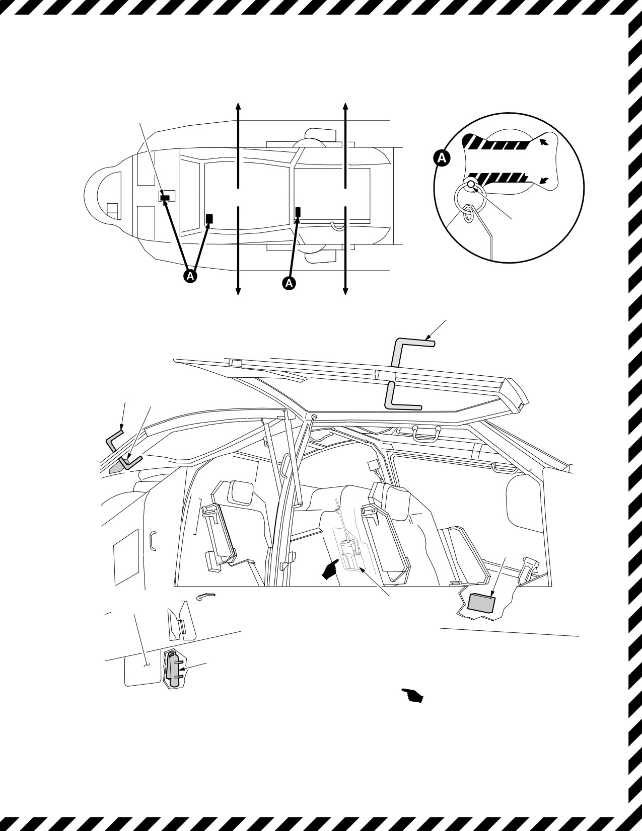
1. EMERGENCY EGRESS
2. INTERNAL CANOPY JETTISON HANDLES
3. MANUAL CANOPY OPENING HANDLES
4. FIRST AID KITS
5
5. PORTABLE FIRE EXTINGUISHER
6. EXTERNAL CANOPY JETTISON HANDLE LOCATION
7. EMERGENCY LOCATOR TRANSMITTER
LBA0083
Figure 9-1. Emergency Equipment and Emergency Exits
Use or disclosure of this information is subject to the restriction(s) on the title page of this document.
Change 2
9-3
TM 1-1520-251-10
9.5.1 Emergency Egress. Emergency exits and equip-
by a rapid drop in NG, NP
, torque, TGT, oil pressure and the
ment (fig 9-1) permit emergency egress by the pilot and
symbolic torque value on the MPD/HMD displays flashing.
CPG from the helicopter. If possible, use the manual
Performance limiting will continue to display normal Ng and
canopy opening handles to open the canopy and exit the
oil pressure indications; as power demand increases, Np and
aircraft. The transparent portion of the four canopy side
NR will collectively decay and the TGT will remain at the en-
panels can be jettisoned by turning any one of three CAN-
gine limiter setting; torque indications will vary as a result of
OPY JETTISON handles 90° and pushing . This will initi-
collective manipulation. Engine failure is annunciated by a
ate canopy side panel jettison. If emergency egress be-
voice message ENGINE 1 (or) 2 out as applicable,
comes necessary, proceed as follows:
[
BLK 1
ENG1 OUT/ENG2 OUT (UFD)] [
BLK 2
EN-
GINE 1 OUT/ENGINE 2 OUT (EUFD] messages, MPD mes-
1. Helmet visors - Down.
sage ENGINE 1 (or) 2 OUT, and flashing MSTR WARN
lighted push button. The MPD will autopage to the ENG Page
2. Area around helicopter - Clear of personnel.
if not already displayed.
3. CANOPY JETTISON handle - Turn 90°, re-
lease, then push to jettison canopy.
A partial engine power loss may follow certain mechanical
failures, such as an ECU/DEC malfunction, or an operator
9.6 ENGINE POWER LOSS - PARTIAL OR
may make a power demand that exceeds an engine’s perfor-
COMPLETE ENGINE MALFUNCTION OR
mance capability. An engine’s performance may be environ-
POWER - LIMITING
mentally limited (high temp, high-pressure altitude/high gross
weight) as a result of TGT, fuel flow and NG/MACH. When a
loss of rotor RPM/performance limitation is encountered, the
WARNING
pilot on the controls should immediately adjust the collective
to maintain NR
within limits; and as conditions warrant, jetti-
Prior to movement of either POWER le-
son the aircraft wing stores. The jettisoning of wing stores will
ver, it is imperative that the malfunction-
immediately reduce the aircraft’s gross weight and corre-
ing engine and the corresponding POW-
spondingly reduce power requirements. Additionally, at low
ER lever be identified.
speeds the pilot on the controls should coordinate flight into
the prevailing wind. When practical, consideration may be
9.6.1 Flight Characteristics. The flight characteristics and
given to making a right banking turn or a right pedal turn to
the required crewmember control response after a dual en-
aid in reducing the immediate power requirements.
gine failure are similar to those during a normal power-on de-
scent. Full control of the helicopter can be maintained during
A left banking turn or left pedal turn will require more power.
autorotational descent. When one engine has failed, com-
Proper use and understanding of the PERF page and the ap-
pletely or partially, the helicopter can often maintain altitude
plication of PERF calculations will significantly reduce the po-
and airspeed until a suitable landing site can be selected.
tential for engine performance limiting. Caution must be exer-
Whether or not this is possible becomes a function of such
cised when operating close to an engine performance limit.
combined variables as aircraft weight, density altitude, and
For example, when operating near the dual engine TGT limit-
airspeed at the time of the engine failure. The jettisoning of
er setting, a gust of wind from aircraft’s rear or left, or an ac-
wingstores will immediately reduce an aircraft’s gross weight
tivation of the engine anti-ice could result in a reduction of
and correspondingly reduce power requirements. Crewmem-
available engine power. The aircrew should not engage any
ber response time and control technique may be additional
hold modes when operating near the dual engine limiter set-
factors.
ting.
9.6.2 Engine Failure and Engine Power Loss: Gener-
al. The various conditions under which an engine may fail
The reduction required in collective after engine failure will
or experience a power loss, prevent a standard procedure for
vary with the altitude and airspeed at the time of failure. For
all cases. A thorough knowledge of both emergency proce-
example, the collective should not be reduced when an en-
dures and flight characteristics will enable the pilot to respond
gine fails while the helicopter is hovering below 15 ft. During
correctly and automatically in an emergency. Engines may
cruise flight, when altitude and airspeed permit a significant
fail partially or performance limit. The degree of the failure/
reduction in collective pitch, NR can be restored to 101% be-
amount of power loss is factored into crewmember response.
fore landing. During single-engine flight or during autorotation,
The engine instruments often provide ample warning of an
airspeed should be kept at the optimum (fig 9-2). Engine fail-
impending failure by deviating from normal indications. An
ure accompanied by an explosion or loud noise would indi-
impending engine TGT limiter activation will not provide any
cate engine damage, and there is a possibility that an attempt
cues prior to functioning. Engine failure is normally indicated
to restart the engine would result in a fire.
Use or disclosure of this information is subject to the restriction(s) on the title page of this document.
9-4
Change 2
TM 1-1520-251-10
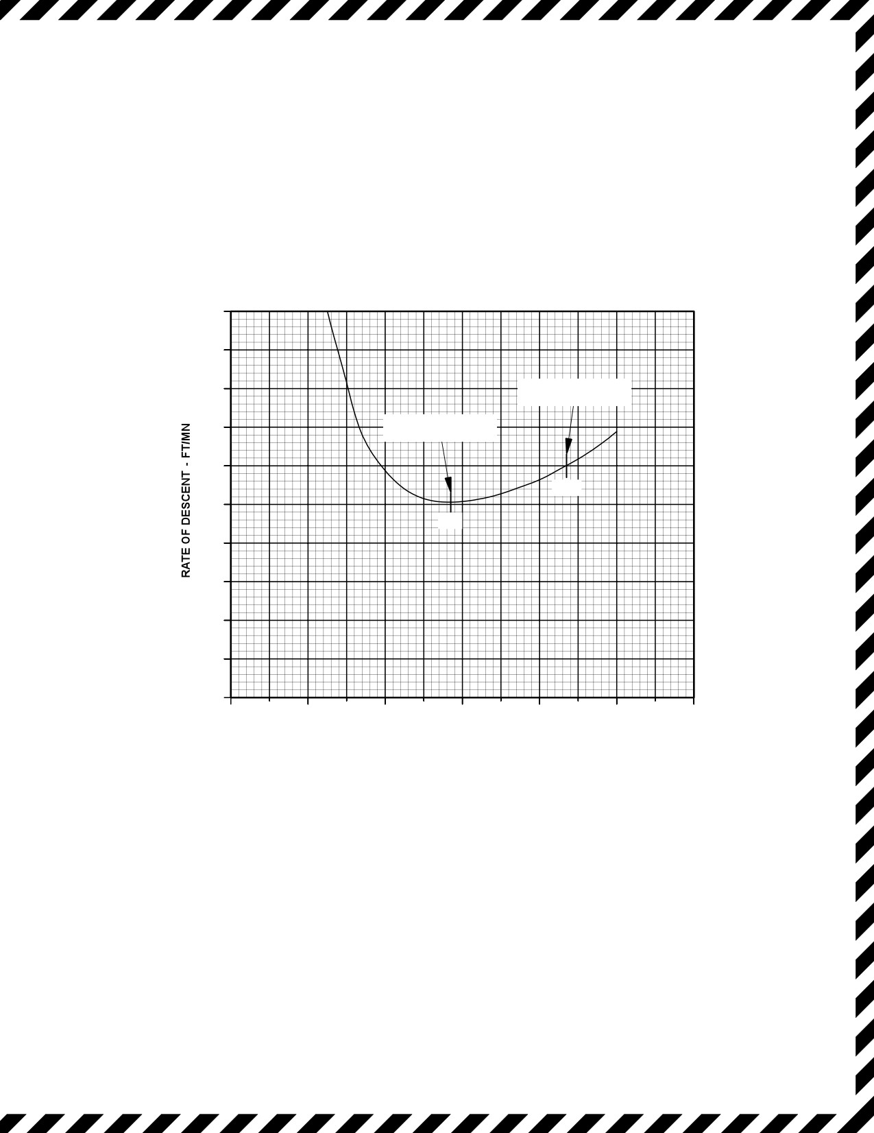
AUTOROTATIONAL DESCENT
POWER OFF, N
R = 101%
SEA LEVEL STD
5000
4500
MAXIMUM
GLIDE
4000
DISTANCE
AIRSPEED
3500
MINIMUM RATE OF
DESCENT AIRSPEED
3000
107
2500
77
2000
1500
1000
500
0
20
40
60
80
100
120
140
TRUE AIRSPEED - KNOTS
LBA1144
Figure 9-2. Autorotative Glide Chart
Use or disclosure of this information is subject to the restriction(s) on the title page of this document.
Change 2
9-5
TM 1-1520-251-10
9.6.3
Single-Engine Failure: General. Proper re-
9.7 SINGLE ENGINE FAILURE - LOW
sponse to an engine failure depends on various factors:
ALTITUDE/LOW AIRSPEED AND CRUISE
density altitude, airspeed, aircraft weight, single-engine
performance, and environmental conditions. The un-
A voice message will announce ENGINE 1 OUT (or) EN-
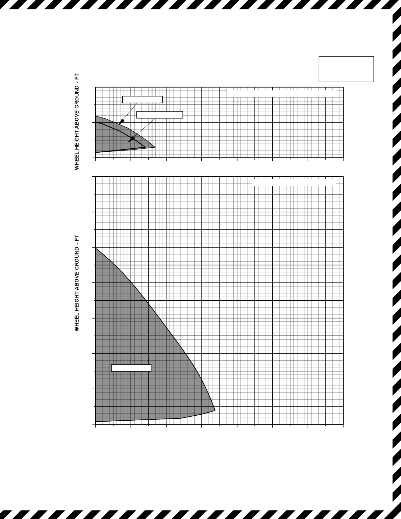
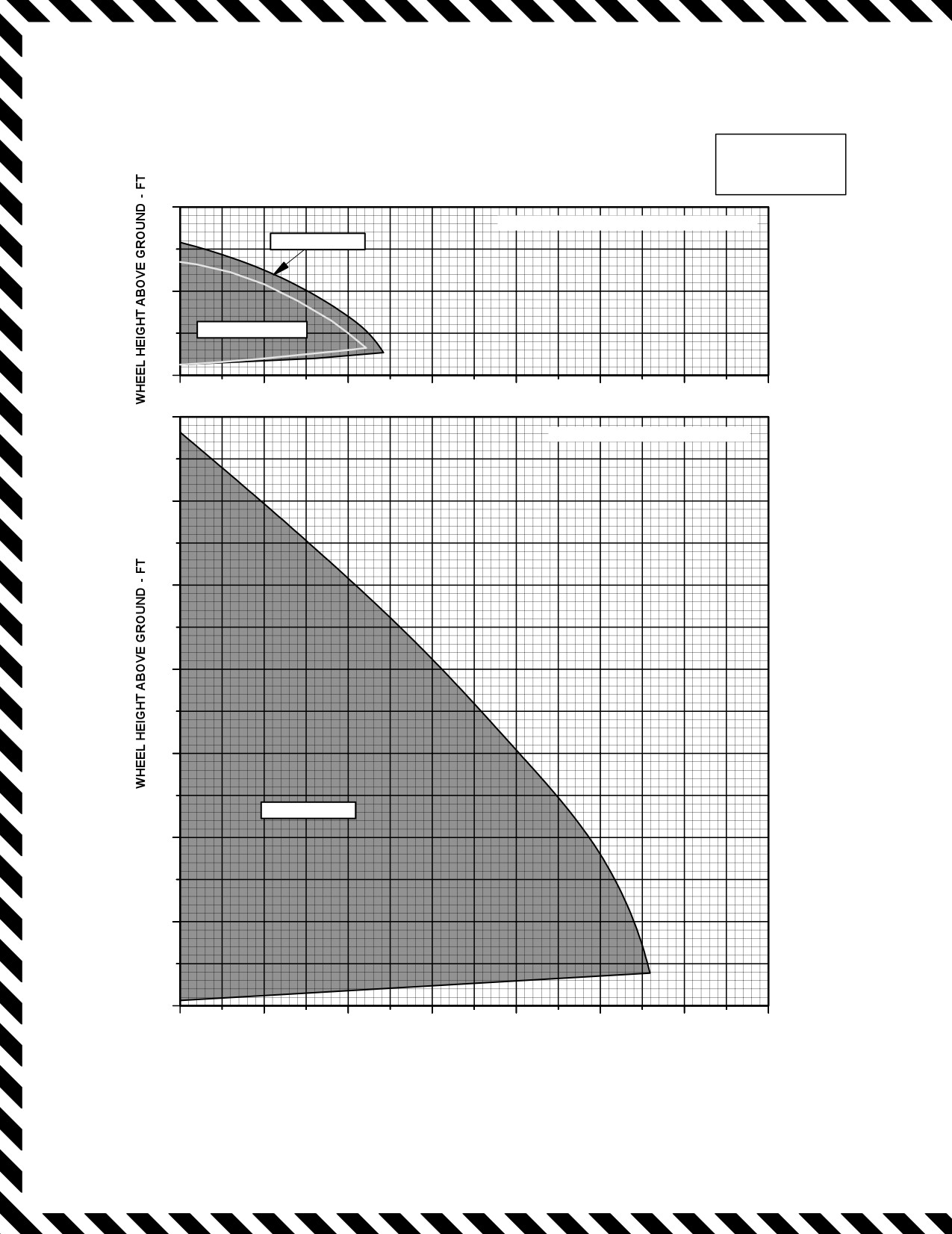
shaded region in the height velocity diagrams (figs 9-3)
GINE 2 OUT. The [
BLK 1
UFD will display ENG1 OUT/
represent the air speed and wheel height combinations
ENG2 OUT ]. The [
BLK 2
EUFD will display ENGINE 1
that will permit a safe landing in event of an engine failure
OUT/ENGINE 2 OUT.]
with average pilot alertness, skill, and reaction time. The
avoid, shaded, region represents hazardous airspeed and
1. WING STORES JETTISON - As appropriate.
wheel - height combinations from which a single engine
landing would be extremely difficult without some degree
2. LAND AS SOON AS PRACTICABLE.
of aircraft damage or crewmember injury. Crewmember
alertness, correct recognition and subsequent actions are
9.8
ENGINE RESTART DURING FLIGHT
essential to perform a single engine landing. Crewmem-
ber actions should be based on the following general
WARNING
guidelines:
• A failed engine should not be re-
• At low density altitude and low airspeed, it may be
started unless it can be determined
necessary to lower the collective only enough to
that it is reasonably safe to do so.
maintain NR in the normal range.
•
When attempting to restart ENG1 fol-
lowing a single engine failure, a mal-
• At higher density altitude the collective may be
functioning crossfeed valve could
lowered significantly to increase Nr to the normal
cause the remaining engine (ENG2) to
range.
fail.
NOTE
• When hovering in ground effect, the collective
should be used only as required to cushion the
• After an engine failure in flight, an engine
landing, primary consideration is in maintaining a
restart may be attempted.
level attitude.
•
Inflight restarts do not need to utilize a
warm start procedure.
• In forward flight at low altitude (as in takeoff or
landing), when a single-engine capability to main-
9.9
DUAL ENGINE FAILURE: GENERAL
tain altitude does not exist, a decelerating attitude
will initially be required to prepare for landing.
WARNING
• If airspeed is low and altitude above the obstacles
In the event of an inadvertent activation
is sufficient, the helicopter should be placed in an
of the engine chop switch, initial indica-
accelerating attitude to gain sufficient airspeed for
tions from NP and NR could be inter-
single-engine fly-away to a selected landing site.
preted as a dual engine failure. Engine
chop is annunciated by a voice message
• When the power available during single-engine
ENGINE CHOP, UFD/EUFD, and MPD
operation will not support continued flight, the crew
messages ENG CHOP/ENGINE CHOP
should jettison external wing stores as an immedi-
and engine idle indications for NG, TGT,
ate means of reducing power requirements.
and NP .
Use or disclosure of this information is subject to the restriction(s) on the title page of this document.
9-6
Change 3
TM 1-1520-251-10
9.9.1 Both Engines Fail. If both engines fail, immedi-
9.9.2 Momentary RPM Increase. Main rotor rpm will
ate action is required to make a safe autorotation descent.
increase momentarily when the cyclic is moved aft with no
The altitude and airspeed at which a two-engine failure
change in collective pitch setting. An autorotation rpm of
occurs will dictate the action to be taken. After the failure,
approximately 101% provides for a good rate of descent.
main rotor rpm will decay rapidly and the aircraft will yaw
NR above 101% may result in a higher than desired rate of
to the left. Unless a two-engine failure occurs near the
descent. At 75 to 125 ft AGL, use aft cyclic to decelerate.
ground, it is mandatory that autorotation be established
This reduces airspeed and rate of descent and causes an
immediately. During cruise at airspeeds to VNE, reduce
increase in NR. The degree of increase depends upon the
collective immediately to regain NR and then adjust as re-
amount and rate of deceleration. Ground contact should
quired to maintain rpm. The cyclic should be adjusted as
be made with some forward speed. If a rough landing area
necessary to attain and maintain the desired airspeed of
is selected, a more pronounced deceleration is necessary
77 to 107 KTAS. In autorotation, as airspeed increases
and touchdown speed should approach zero. It is possible
above 70 - 80 KTAS, the rate of descent and glide dis-
that during the autorotative approach, the situation may
tance increase significantly. Below 70 KTAS, the rate of
require additional deceleration. In that case, it is neces-
descent will also increase, but glide distance decreases.
sary to assume a landing attitude at a higher altitude than
Autorotation during an out of trim condition will increase
normal. Should both engines fail at low airspeed, initial
the rate of descent and decrease the glide distance. A
collective reduction may be necessary to maintain NR
landing area must be selected immediately after both en-
within normal range. In some instances at low altitude or
gines fail, and control inputs must be made to fly to the in-
low airspeed, settling may be so rapid that little can be
tended site. Throughout the descent, adjust collective as
done to avoid a hard-impact landing. In that case, it is criti-
necessary to maintain NR within normal range. At high
cal to maintain a level landing attitude. Cushion the land-
gross weights, the rotor may tend to overspeed and the
ing with remaining collective as helicopter settles to the
collective must be used to maintain the desired rotor rpm.
ground.
NR should be maintained at or slightly above 101% to al-
low ample rpm before touchdown, and heading main-
tained by pedals.
Use or disclosure of this information is subject to the restriction(s) on the title page of this document.
Change 2
9-7
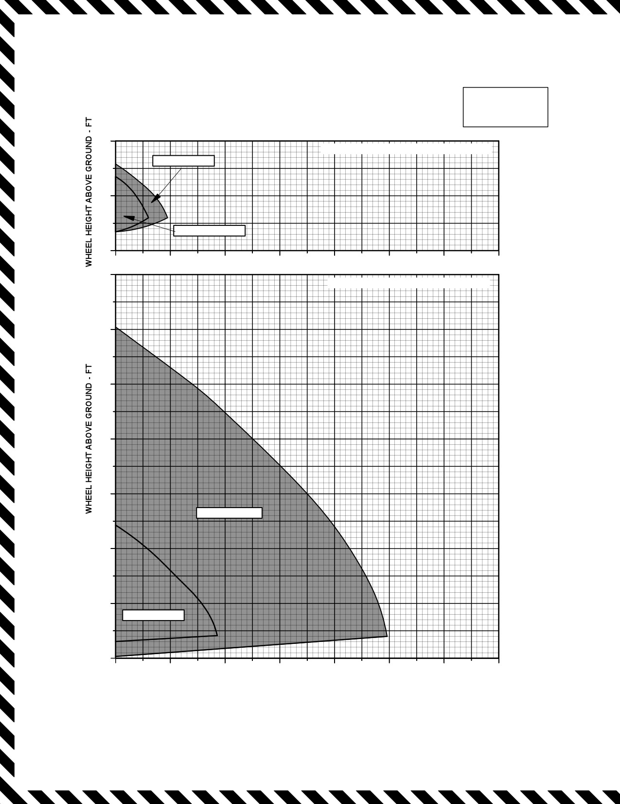
TM 1-1520-251-10
HEIGHT - VELOCITY
SINGLE - ENGINE FAILURE
HEIGHT - VELOCITY
STD TEMP, ZERO WIND
AH - 64D
GROSS WEIGHT = 16,500 LB OR LESS
200
PRESSURE ALTITUDE = SEA LEVEL AND 2500 FT
2,500 FT AVOID
100
SEA LEVEL AVOID
0
0
10
20
30
40
50
60
70
AIRSPEED - KTAS
700
PRESSURE ALTITUDE = 6,000 AND 10,000 FT
600
500
400
300
10,000 FT AVOID
200
100
6,000 FT AVOID
0
0
10
20
30
40
50
60
70
DATA BASIS: ESTIMATED WITH HELICOPTER DYNAMIC
AIRSPEED - KTAS
PERFORMANCE (HDP) PROGRAM
LBA1145
Figure 9-3. Height Velocity Plots (Sheet 1 of 3)
Use or disclosure of this information is subject to the restriction(s) on the title page of this document.
9-8
Change 2
TM 1-1520-251-10
HEIGHT - VELOCITY
SINGLE - ENGINE FAILURE
HEIGHT - VELOCITY
STD TEMP, ZERO WIND
AH - 64D
GROSS WEIGHT = 18,280 LB
400
PRESSURE ALTITUDE = SEA LEVEL AND 2500 FT
2,500 FT AVOID
SEA LEVEL AVOID
200
0
0
10
20
30
40
50
60
70
AIRSPEED - KTAS
700
PRESSURE ALTITUDE = 6,000 FT
600
500
400
300
200
6,000 FT AVOID
100
0
0
10
20
30
40
50
60
70
DATA BASIS: ESTIMATED WITH HELICOPTER DYNAMIC
AIRSPEED - KTAS
PERFORMANCE (HDP) PROGRAM
LBA2536
Figure 9-3. Height Velocity Plots (Sheet 2 of 3)
Use or disclosure of this information is subject to the restriction(s) on the title page of this document.
Change 2
9-9
TM 1-1520-251-10
HEIGHT - VELOCITY
SINGLE - ENGINE FAILURE
HEIGHT - VELOCITY
STD TEMP, ZERO WIND
AH - 64D
GROSS WEIGHT = 20,260 LB
400
PRESSURE ALTITUDE = SEA LEVEL AND 2500 FT
2,500 FT AVOID
200
SEA LEVEL AVOID
0
0
10
20
30
40
50
60
70
AIRSPEED - KTAS
700
PRESSURE ALTITUDE = 6,000 FT
600
500
400
300
6,000 FT AVOID
200
100
0
0
10
20
30
40
50
60
70
DATA BASIS: ESTIMATED WITH HELICOPTER DYNAMIC
AIRSPEED - KTAS
PERFORMANCE (HDP) PROGRAM
LBA2537
Figure 9-3. Height Velocity Plots (Sheet 3 of 3)
Use or disclosure of this information is subject to the restriction(s) on the title page of this document.
9-10
Change 2

TM 1-1520-251-10
9.10 DUAL ENGINE FAILURE - LOW ALTITUDE/LOW
9.12 ENGINE ALTERNATOR MALFUNCTION
AIRSPEED AND CRUISE
CAUTION
A voice message will announce ENGINE 1 OUT and EN-
GINE 2 OUT. The [
BLK 1
UFD will display ENG1 OUT
•
- Complete failure of the alternator
and ENG2 OUT.] The [
BLK 2
EUFD will display EN-
or of the winding providing NG speed
GINE 1 OUT and ENGINE 2 OUT.]
signal will activate the MSTR WARN
light and engine 1 out or engine 2 out
voice message and UFD/EUFD mes-
sages. The pilot shall check the NR
on
CAUTION
ENG page and be prepared to carry
out the actions for a high side failure.
Thereafter, refer to TGT and engine oil
With the POWER levers in FLY, resetting
PSI, along with engine fuel PSI and
the CHOP button will cause an erro-
nose gearbox oil PSI messages.
neous engine 1 out and engine 2 out
warning to be activated.
•
- Following a complete failure of
an alternator, operation of the corre-
sponding engine and all indications
1. AUTOROTATE.
from engine instruments will be nor-
mal, except that NG indications will be
lost and will activate the MSTR WARN
2. CHOP button - Reset only if an engine chop
light and engine 1 out or engine 2 out
warning message is present.
voice message and UFD/EUFD mes-
sages.
3. WING STORES JETTISON - As appropriate.
The engine alternator has three windings, providing pow-
er for engine ignition, aircraft NG speed indication, and
9.11 ENGINE 1 OR 2 OVERSPEED - NP FAILED HIGH
electrical control system operation. A failure of the ignition
winding would result in loss of electrical power to the igni-
tion circuitry which would be detected by inability to start
A voice message will announce ENGINE 1 OVERSPEED
the engine. A failure of the winding providing NG speed in-
or ENGINE 2 OVERSPEED. The [
BLK 1
UFD will dis-
dication signal would not affect actual engine operation;
play ENG1 OVSP or ENG2 OVSP.] The [
BLK 2
EUFD
however, the pilot would have no NG indication. A failure
will display ENGINE 1 OVERSPEED or ENGINE 2 OVER-
of the winding providing electrical power to the engine
SPEED.]
ECU
is the most severe and requires immediate ac-
tion by the pilot. The immediate indication to the pilot may
be the affected engine accelerating to maximum power.
1. Collective - Adjust to maintain NR within limits.
There will also be a loss of Np and torque indication. If this
failure is due to a complete loss of the alternator, then no
NG indication will be present either. The engine TGT will
If condition persists:
still be indicating because it is not acted upon by the ECU
; however, TGT limiting will no longer be available. Np
2. POWER lever (affected engine) - Retard to
overspeed protection will be present because aircraft
equalize torque.
power is supplied for that function. If an alternator failure is
suspected and the affected engine accelerates to maxi-
mum power, proceed as in ENGINE 1 or 2 OVERSPEED
3. LAND AS SOON AS PRACTICABLE.
- Np FAILED HIGH.
Use or disclosure of this information is subject to the restriction(s) on the title page of this document.
Change 2
9-11
TM 1-1520-251-10
9.13 LOW RPM ROTOR - NP FAILED LOW
1. Collective - Reduce.
NOTE
If condition persists:
Advancing the POWER lever of the engine
2. POWER lever (affected engine) - Retard.
with low torque and TGT to LOCKOUT dis-
ables the automatic temperature limiting for
If TGT decreases and there is no further evi-
that engine. The engine must be controlled
dence of a stall;
manually to ensure that it does not exceed
operating limits.
3. POWER lever (affected engine) - FLY.
LOW ROTOR RPM indications may be the
If stall condition recurs:
result of one or both 701 or 701C engines
having entered a performance-limiting
4. POWER lever (affected engine) - IDLE.
condition. Refer to paragraph 9.6.2 Engine
Failure and Engine Power Loss for proce-
5. LAND AS SOON AS PRACTICABLE.
dural information.
A voice message will announce ROTOR RPM LOW. The
9.15 ROTORS, TRANSMISSIONS, AND DRIVE
[
BLK 1
UFD will display LOW RTR.] The [
BLK 2
SYSTEMS
EUFD will display LOW ROTOR RPM.]
1. Collective - Adjust to maintain NR within limits.
WARNING
If condition persists:
Pilot situational awareness is critical in
the successful accomplishment of these
2. POWER lever (affected engine) - LOCKOUT
procedures. The low inertia rotor sys-
and then retard to equalize torque output of both
tem, coupled with high rates of descent
engines.
during vertical autorotation, may not
provide the pilot with adequate reaction
If manual control is not possible:
time and cushioning pitch. Activation of
3. POWER lever (affected engine) - IDLE.
the CHOP button or reduction of the
POWER levers prior to reduction of the
4. LAND AS SOON AS PRACTICABLE.
collective will result in a rapid decay of
rotor rpm. Successful completion of an
If continued flight is not possible, proceed as in paragraph
out-of-ground effect hovering autorota-
9.7 SINGLE ENGINE FAILURE.
tion is doubtful.
9.14 ENGINE COMPRESSOR STALL
CAUTION
An engine compressor stall is normally recognized by a
noticeable bang or popping noise and possible aircraft
If engine chop is used to minimize main
yaw. These responses are normally accompanied by a
rotor torque, increasing collective pitch
rapid increase in TGT and fluctuations in NG, TORQUE,
without first retarding POWER levers to
and NP readings for the affected engine. In the event of a
IDLE may cause engine acceleration and
compressor stall:
uncommanded yaw.
Use or disclosure of this information is subject to the restriction(s) on the title page of this document.
9-12
Change 2

TM 1-1520-251-10
9.15.1
Tail Rotor Malfunctions. These procedures
direction. Care should be taken to use minimum collective
represent a best estimate of helicopter reactions and crew
pitch to cushion the landing during touchdown. After
procedures. The most critical consideration in responding
touchdown, the wheel brakes should be used to maintain
to any tail rotor malfunction is that the crewmember cor-
heading and the collective should be lowered to minimize
rectly interprets the nature and extent of the problem. Tail
torque effect
wheel shall be locked during all landings.
1. Airspeed - 90 KTAS minimum (until 10 to 20 ft
above touchdown).
9.15.2 Loss of Tail Rotor Thrust - General. Loss of
tail rotor thrust occurs when there is a break in the drive
2. WING STORES JETTISON - As appropriate.
system; for example, a severed drive shaft. The nose of
3. POWER levers - Retard as necessary (5 to 10 ft
the helicopter will turn to the right. If the helicopter is in for-
above touchdown).
ward flight, there will be a right roll of the fuselage along
the longitudinal axis, and the nose of the helicopter may
b. Continued Flight Not Possible. If powered
pitch downward. This downward pitch will be more pro-
flight is not possible at an airspeed sufficient to maintain
nounced if a tail rotor component has been separated
helicopter control, enter autorotation, and power levers
from the helicopter. In some cases, depending on the se-
off. In autorotation, the sideslip and roll angles can be sig-
verity of the right rotation, powered flight to an acceptable
nificantly reduced by maintaining a sufficient high air-
landing site may be accomplished by maintaining or in-
speed to allow the fuselage to streamline. A roll-on land-
creasing airspeed. The degree of sideslip and amount of
ing during touchdown will minimize the required pitch
roll may be varied by changing airspeed and by varying
application and should be used if terrain permits.
collective pitch. Neither, however, can be completely elim-
inated.
1. AUTOROTATE.
9.15.3 Loss of Tail Rotor Thrust in Cruise Flight.
2. POWER levers - OFF (prior to touchdown).
3. WING STORES JETTISON - As appropriate.
WARNING
9.15.4 Loss of Tail Rotor Thrust at Low Airspeed/Hov-
er. Loss of tail rotor thrust at slow speed may result in
extreme yaw angles and uncontrolled rotation to the right.
If airspeed is allowed to approach effec-
Immediate collective pitch reduction should be initiated to
tive translational lift, the sideslip angle
reduce the yaw and begin a controlled rate of descent. If
may become quite severe and helicopter
the helicopter is high enough above the ground, an at-
control may be lost.
tempt should be made to increase airspeed to streamline
the helicopter. This may permit continued flight with a sta-
bilized and manageable yaw angle. If this increase does
a. Continued Flight Possible. At cruise airspeeds,
reduce yaw, proceed as outlined for Loss of Tail Rotor
it may be possible that level flight at some stabilized yaw
angle can be maintained. The degree of sideslip will de-
Thrust in Cruise Flight - Continued Flight Possible. If the
pend on the airspeed and power required to maintain
aircraft cannot be accelerated into forward flight, initiate a
flight. Some left cyclic should be used to stop the slow
power-on descent. Collective should be adjusted so that
right turn induced by the loss of thrust. Care should be tak-
an acceptable compromise between rate of turn and rate
en to avoid slowing the helicopter. The airspeed indicator
of descent is maintained. At approximately 5 to 10 ft
may not provide useful information once the sideslip is es-
above touchdown, perform a hovering autorotation by
tablished, but true airspeed, yaw angle, engine torque,
POWER levers - OFF.
and rate of climb or descent should provide cues neces-
NOTE
sary to maintain flight. If yaw angle becomes excessive,
reduce power and lower the nose to retain adequate air-
Continuous right rotation during descent
speed. A minimum of 90 KTAS during a shallow approach
and touchdown can be expected.
to a roll on landing should be maintained until approxi-
mately 10 to 20 ft above the touchdown point. Begin a
1. Collective - Reduce.
gradual deceleration to arrive at approximately 5 to 10 ft
above touchdown as the yaw angle begins to increase (to
the right). At this point, retard the POWER levers as nec-
2. POWER levers - OFF (5 to 10 ft above touch-
essary to align the helicopter fuselage with the landing
down).
Use or disclosure of this information is subject to the restriction(s) on the title page of this document.
Change 2
9-13
TM 1-1520-251-10
9.15.5 Tail Rotor Fixed Pitch Malfunction. A fixed
9.15.6 Main Transmission Input Drive Clutch Failure.
pitch failure may be evidenced by slow, intermittent, or no
An input drive clutch malfunction is most likely to occur
response to pedal input or no pedal movement. A left or
during engine start or when an engine POWER lever is
right yaw may be apparent.
advanced. Indications may include:
• Erratic torque indication on affected engine.
• Complete loss of torque indication on affected
a. In-Ground Effect. If a failure occurs during in-
engine.
ground-effect hover, reaction may vary from adjusting col-
lective and POWER levers during a left rotation to activat-
• NP of affected engine exceeding NR.
ing the CHOP button to stop a right rotation. In any case,
the primary concern should be to land the aircraft with as
If the failure is a sudden disengagement, the torque of the
little yaw rate as possible.
opposite engine will double as it attempts to carry the
load. A sudden high torque input drive clutch engagement
• If the aircraft has an uncontrolled turn to the left, a
may cause severe engine and/or drive train damage. A
reduction in the POWER levers coordinated with
sudden engagement is indicated by a loud noise and/or
an increase in collective may slow or stop the
sudden increase in engine torque. Should an input drive
rotation so that a controlled power on descent to
clutch malfunction occur, perform the following:
landing can be accomplished.
CAUTION
• If the aircraft is not turning, a slight reduction in
collective pitch will begin a descent. During the
• When a clutch fails to disengage,
descent, a slight rotation to the left may be present;
damage to the affected engine will re-
increasing collective just prior to touchdown
sult (due to lack of oil pressure) if both
should stop the rotation.
engines are not shutdown simulta-
neously.
• If the aircraft has an uncontrolled turn to the right,
reduce collective to begin descent. At approxi-
• When a clutch fails to engage, do not
shut down both engines simulta-
mately
5 to
10 ft AGL, perform a hovering
neously. Damage may result if there is
autorotation by CHOP button - Press or POWER
sudden engagement.
Levers - OFF.
a. In Flight.
b. Out-of-Ground Effect.
1. POWER lever (affected engine) - IDLE.
• If little or no right rotation or if left rotation is
If NP (affected engine) is below NR (indicating the clutch is
experienced and control can be maintained, the
disengaged).
aircraft should be accelerated into forward flight
and perform approach and landing appropriate to
2. EMER ENG SHUTDOWN (affected engine).
power setting and condition of flight at time of
failure.
3. LAND AS SOON AS PRACTICABLE.
• If the aircraft cannot be accelerated into forward
If NP (affected engine) does not drop below NR (indicating
flight, initiate a power-on descent. Collective
the clutch has failed to disengage).
should be adjusted so that an acceptable compro-
mise between rate of turn and rate of descent is
4. LAND AS SOON AS POSSIBLE.
maintained. At approximately 5 to 10 ft above
touchdown, perform a hovering autorotation by
5. EMER ENG(S) SHUTDOWN (both engines si-
CHOP button - Press or POWER levers OFF.
multaneously).
Use or disclosure of this information is subject to the restriction(s) on the title page of this document.
9-14
Change 2
TM 1-1520-251-10
b. On Ground.
(with indications that a clutch has
permits, a MAYDAY radio call should be made before
failed to engage).
electrical power is OFF to expedite assistance from fire
fighting equipment and personnel. If airborne, the most
1. EMER ENG SHUTDOWN (affected engine
important single action that can be taken by the crew is to
only).
land the helicopter. If time permits, a radio call should be
made to expedite assistance from fire fighting personnel.
2. Check NG is less then 10% (affected engine).
Consideration should be given to jettisoning external
stores prior to landing.
3. Normal engine shutdown - Perform.
WARNING
c. On Ground.
(with indications that a clutch has
failed to disengage).
Prior to moving PWR lever or pressing
EMER ENG(S) SHUTDOWN (both engines si-
any ENG FIRE button, either achieve a
multaneously).
safe single engine airspeed or prepare
for a single engine landing.
9.16
FIRES
9.16.1 Engine Fire - In Flight. If an ENG1 or ENG2
NOTE
FIRE push button on the FIRE DET/EXT panel illumi-
nates, a voice message will announce ENGINE 1 (or) EN-
• The FIRE switches will remain illumi-
GINE 2 ON FIRE. When the fire is confirmed:
nated until the sensors no longer detect a
fire. For a crewstation to discharge or re-
1. EMER ENG SHUTDOWN (affected engine) -
set the system, that crewstation FIRE
when conditions permit.
pushbutton must be armed/dearmed.
• Signals sent from the Signal Processor
2. Illuminated ENG FIRE button - Press and RDY
(SP) will automatically turn off the Air Par-
light illuminates.
ticle Separator (APS) blower under ALL
fire detection conditions. ”AFT DECK
3. FIRE DISCH button(s) - Press.
FIRE”, ”ENGINE 1 (or) 2 FIRE”, and
”APU FIRE” preventing smoke ingestion
4. LAND AS SOON AS POSSIBLE.
into the ECS fresh air system via the APS
blower inlet.
9.16.2 APU Compartment Fire. If fire is observed in
APU compartment, a voice message will announce
• The PRI bottle should be selected first; in
APU FIRE.
the event of a malfunction or failure to ex-
tinguish the fire, select RES.
a. On Ground:
• If APU is running, accomplish an APU
shutdown prior to evacuating the aircraft.
1. APU - OFF..
The safety of the helicopter occupants is the primary con-
2. Illuminated APU FIRE button - Press and RDY
sideration when a fire occurs. On the ground, it is essen-
light illuminates.
tial that the engine(s) be shut down, the crew eva-
cuated, and fire fighting begin immediately. If time
3. FIRE DISCH button(s) - Press.
Use or disclosure of this information is subject to the restriction(s) on the title page of this document.
Change 4
9-15
TM 1-1520-251-10
b. In Flight:
9.16.6 Electrical Fire In Flight. Prior to shutting off all
electrical power, the pilot must consider the equipment
that is essential to a particular flight environment which
1. Illuminated APU FIRE button - Press and RDY
will be affected; e.g., flight instruments, flight controls, etc.
light illuminates.
With electrical power off, engine anti-ice is automatically
ON. If an immediate landing cannot be made, the defec-
2. FIRE DISCH button(s) - Press.
tive circuit may be isolated by selectively turning off elec-
trical equipment.
3. LAND AS SOON AS POSSIBLE.
1. GEN1 and GEN2 - OFF (SYS page).
9.16.3 Deck Fire. If fire is observed in the deck area or
if the AFT DECK FIRE warning is annunciated which will
2. LAND AS SOON AS POSSIBLE.
activate an AFT DECK FIRE voice message. The UFD/
EUFD will display an aft deck fire message.
9.16.7 Smoke and Fume Elimination.
LAND AS SOON AS POSSIBLE.
1. Airspeed - Slow to 20 KTAS maximum.
2. Canopy door (affected crewstation) - Open to
9.16.4 Engine Fire On Ground. If an engine fire is de-
intermediate position.
tected while aircraft is on the ground, a voice message will
announce ENGINE 1 or 2 FIRE and pushbuttons illumi-
3. LAND AS SOON AS POSSIBLE.
nate. When fire is confirmed:
9.16.8 Aborting Engine Start.
1. EMER ENG(S) SHUTDOWN.
WARNING
2. Illuminated ENG FIRE button - Press and RDY
light illuminates.
Aborted engine starts may cause
fuel to collect in the engine nacelle. Sub-
3. FIRE DISCH button(s) - Press.
sequent engine starts may be attempted
only after the nacelle door/work platform
9.16.5 Fuselage Fire On Ground. If a fuselage fire is
is opened and the nacelle inspected for
observed and a fire warning has not been annunciated:
fuel. If during the initial start an abnormal
TGT rise was evident, or fuel is evident in
1. EMER ENG(S) SHUTDOWN.
the nacelle, the ignition system shall be
checked IAW standard maintenance pro-
2. APU - OFF (If applicable).
cedures.
Use or disclosure of this information is subject to the restriction(s) on the title page of this document.
9-16
Change 4

TM 1-1520-251-10
9.17
ELECTRICAL SYSTEM MALFUNCTIONS
CAUTION
NOTE
• In the event of an In - Flight electrical sys-
Abort start for any of the following rea-
tem malfunction, the power interrupt
sons:
protection may cause blanking of one or
more MPDs for as long as 6 seconds.
When on the ground during an electrical
• If it becomes apparent that TGT will
system malfunction, MPD blanking may
exceed 869° C
or 851° C
be-
occur up to 12 seconds in duration due to
fore NG idle speed (63% or more) is at-
increased BIT cycle.
tained.
• Failure or reset of the number two (2)
generator may result in BUCS FAIL cau-
• If TGT does not increase within 45 se-
tion and FMC DISENGAGE and a loss of
one or more channels of SAS. After com-
conds after moving POWER lever to
pleting the Generator Fail emergency
IDLE.
procedure (GEN RESET), reset the
BUCS FAIL and the FMC DISENGAGE
• If no NP within 45 seconds after mov-
by re-engaging the affected SAS chan-
ing POWER lever to IDLE (unless rotor
nels. If the BUCS FAIL is not associated
with the GEN FAIL or the reset, the pilot
is locked).
should assume other problems have oc-
curred and complete the BUCS FAIL
• If positive oil pressure indication does
emergency procedure.
not occur within 45 seconds after
• A battery charged to 80% will normally
moving POWER lever to IDLE.
supply the battery busses for approxi-
mately 12 minutes at 25° C. Time will de-
• If engine 1 or 2 start advisory is re-
crease accordingly if the temperature is
moved prior to attaining 52% NG.
increased or decreased from 25° C.
9.17.1 Both Generators Fail/Complete Loss Of Elec-
ABORT START PROCEDURES are as follows:
trical Power.
1. POWER lever - OFF.
1. GEN1 and GEN2 - Reset Pilot GEN RST panel.
If condition persists:
2. ENG START switch - IGN ORIDE for 30
seconds or until TGT is below 540° C.
2. LAND AS SOON AS POSSIBLE.
Use or disclosure of this information is subject to the restriction(s) on the title page of this document.
Change 2
9-17
TM 1-1520-251-10
9.17.2 Single Generator and Single RTRU Failure.
9.18
HYDRAULIC SYSTEM MALFUNCTIONS
1. Affected GEN1 or GEN2 - Reset Pilot GEN RST
panel.
WARNING
If condition persists:
• Immediate emergency action must fol-
low failure of both hydraulic systems.
2. LAND AS SOON AS PRACTICABLE.
Any hesitation could result in loss of
helicopter control.
9.17.3 Dual TRU Failure (Transformer Rectifier 1 and
Transformer Rectifier 2).
• With emergency hydraulic power in
use, flight control inputs and elevated
When a dual TRU failure occurs, a number of Cautions
G loading must be kept to an absolute
and Advisories will be displayed on the UFD. These may
minimum.
include BUCS FAIL and FMC FAIL. Conduct Emergency
• Hydraulic power availability is a func-
Procedures for the displayed UFD Cautions in order of im-
tion of the frequency and magnitude
portance. All DC services will be lost, except those pro-
of the control inputs and G loading
vided by the battery. Charging of the battery will no longer
placed on the aircraft. In static condi-
be conducted. The aircrew can expect the following:
tions the hydraulics will bleed down in
a. TADS/PNVS and HDU’s will be inoperative.
approximately 6 minutes. If the con-
trols are moved continuously at an
b. All navigational functions will be lost.
approximate 1hz rate this may be as
little as 30 to 41 seconds.
c. Some primary flight information will be lost (altitude,
heading and airspeed).
• The amount of control movement may
be reduced to zero depending on the
d. FMC functions will be lost.
severity and location of hydraulic fluid
e. Stabilator control will be lost.
loss within the utility hydraulic sys-
tem.
f. Primary crewstation lighting will be lost.
•
Once the EMERG HYD pushbutton is
g. Engine Anti - Ice will activate.
pressed ON, it must remain ON. Flight
control loss will occur when emergen-
h. The Keyboard Unit will be inoperative.
cy accumulator pressure drops to
i. The crew will be able to transmit and receive on the pre
approximately 1650 psi.
set radio frequencies but will not be able to input new
• Failure of both primary and secondary
frequencies with the Keyboard Unit.
drives to the accessory gearbox
j. WP’s will be inoperative and weapons systems will not
would result in the complete loss of all
be functional.
AC power and the failure of both the
Primary Hydraulic System and the
k. The ECS will be inoperative.
Utility Hydraulic System. All electrical
systems, sights, communications,
l. The ice detector will be inoperative.
and lighting equipment not powered
m.The left and right pitot heater will be inoperative.
by the emergency bus would be lost.
The crew must activate the Emergen-
LAND AS SOON AS PRACTICABLE.
cy Hydraulics and land without delay.
Use or disclosure of this information is subject to the restriction(s) on the title page of this document.
9-18
Change 4
TM 1-1520-251-10
9.18.1 Primary Hydraulic Pressure Low and Utility
9.20
DITCHING (POWER ON)
Hydraulic Pressure Low. The UFD/EUFD will display
hydraulic fail message.
WARNING
1. EMERG HYD button -- Press ON.
• Activation of the canopy jettison sys-
tem with the cockpit partially full or
2. LAND WITHOUT DELAY..
submerged full of water will generate a
pressure wave that may result in crew
3. EMER ENG(S) SHUTDOWN.
injury and/or death.
• If the canopy jettison system has not
9.18.2 Primary Hydraulic Pressure Low and Utility
been activated prior to ditching in wa-
Hydraulic Level Low. In the event of a PRI HYD PSI
ter, the external water pressure may
failure and UTIL HYD LVL condition, hydraulic power to
cause the canopies to implode (col-
the Tail Rotor (T/R) servo may be lost. This may require a
lapse inward) as the aircraft sinks be-
landing in accordance with T/R FIXED PITCH MAL-
yond 2 - 3 meters. The cockpit will
FUNCTION. The UFD/EUFD will display TAIL RTR/TAIL
flood almost immediately and the air-
ROTOR HYD.
craft will begin to descend rapidly in
an uncontrolled manner; canopy sec-
LAND AS SOON AS POSSIBLE.
tions may also block the egress route.
9.19 EMERGENCY LANDING IN WOODED AREAS
CAUTION
(POWER OFF)
If the canopy jettison system is operated
AUTOROTATE -- Apply full collective to decay
underwater, the canopies are likely to im-
rotor rpm as helicopter settles.
plode (collapse inward) due to the external
water pressure. This may hinder egress
and/or block escape routes.
The decision to ditch the helicopter will be made by the pi-
lot when an emergency makes further flight unsafe.
1. Approach to hover.
2. Canopies -- JETTISON prior to entering water.
3. Pilot shoulder harness -- Lock.
4. CPG -- Exit helicopter.
5. Hover downwind to a safe distance.
6. POWER levers -- OFF.
7. Perform hovering autorotation -- Apply full col-
lective to decay rpm as helicopter settles.
8. Cyclic -- Position in direction of roll.
9. Exit when main rotor has stopped.
Use or disclosure of this information is subject to the restriction(s) on the title page of this document.
Change 5
9-19
TM 1-1520-251-10
9.21 DITCHING (POWER OFF)
2. APU ON.
3. EMER ENG(S) SHUTDOWN.
If autorotational landing over water becomes necessary:
9.22.4 Main Rotor Components.
1. AUTOROTATE -- Apply full collective to decay
rotor rpm as helicopter settles.
WARNING
2. Canopies -- JETTISON prior to entering water.
Danger exists that the main rotor system
3. Cyclic -- Position in direction of roll.
could collapse or separate from the air-
craft after landing. A decision must be
4. Exit when main rotor has stopped.
made whether occupant egress occurs
before or after the rotor has stopped.
9.22 FLIGHT CONTROL MALFUNCTIONS
Imminent failure of the main rotor components may be in-
dicated by a sudden increase in main rotor vibration and/
9.22.1 Failure of Components. Failure of components
or unusual noise. Severe changes in lift characteristics
within the flight control system may be indicated through
and/or balance condition can occur due to blade strikes,
varying degrees of feedback, binding, resistance, sloppi-
skin separation, shift or loss of balance weights or other
ness or abnormal control responses. These conditions
material. Malfunction may result in severe main rotor flap-
should not be mistaken for the malfunction of the stabiliza-
ping. If the main rotor system malfunctions, proceed as
tion equipment.
follows:
9.22.2 BUCS FAIL.
1. LAND AS SOON AS POSSIBLE.
2. EMER ENG(S) SHUTDOWN.
WARNING
During ground operations any abnormal control inputs re-
• Activation of one of the BUCS FAIL
quired to maintain desired fuselage attitude may be indic-
cautions in--flight shall signal a flight
ative of a problem. If this condition occurs, complete a nor-
control emergency. It can mean either
mal engine shutdown.
a failure within the system or a mis-
9.22.5 EGI IN--FLIGHT MISALIGNMENT.
track between the crewstation con-
trols. The CPG should only activate
the BUCS trigger select if the pilot is
CAUTION
incapable of maintaining control of
the aircraft.
In flight, depending on airspeed, an un-
commanded scheduling down of the sta-
• If BUCS has been activated, attempt to
bilator can generate significant aircraft
land as far away from any known
pitch changes and decelerative forces.
transmitters as practical.
The instinctive aft cyclic input applied
will begin to slow the aircraft. However, a
1. LAND AS SOON AS POSSIBLE.
reduction in collective generates an
additional pitch down moment which ag-
2. APU ON.
gravates the situation and should be
avoided.
3. EMER ENG(S) SHUTDOWN.
NOTE
9.22.3 BUCS ON. Activation of the BUCS ON caution
• Dual in--flight EGI alignments are prohib-
informs the crew that the BUCS system is now in use to
ited.
control one or more flight control axes. The system is a
non--redundant fly--by--wire system and long duration
• Single in--flight alignments are authorized
flights should not be attempted.
on the secondary EGI, however, level un-
accelerated flight with a constant heading
1. LAND AS SOON AS POSSIBLE.
must be maintained.
Use or disclosure of this information is subject to the restriction(s) on the title page of this document.
9-20
Change 5
TM 1-1520-251-10
Section II.
MISSION EQUIPMENT
9.26 MISSION EQUIPMENT FAILURE
a. PNVS Failure.
CAUTION
NOTE
Do not jettison Hellfire missile if a hangfire is
Switch over to the TADS WFOV FLIR image
in progress.
should occur in about 3 seconds. TADS
slew rates noticeably slower in azimuth than
9.26.1 Wing Stores Jettison.
PNVS. Some gain and level adjustment is
usually necessary for optimum image.
a. Selected Armament Wing Stores.
1. Airspeed - 130 KTAS maximum.
NVS select switch (Pilot) - TADS.
2. Selected STORES JETTISON
buttons - Press to ARM.
b. IHADSS/HDU Failure or [
BLK 2
IHADSS
3. JETT button - Press.
STALE]. If necessary, the following procedure will en-
able the flight crew to fly an MPD fixed panel mounted dis-
b. All Armament Wing Stores:
play.
1. Airspeed - 130 KTAS maximum.
2. Collective JETT button - Press.
1. NVS MODE switch - FIXED.
c. External Fuel Wing Stores:
2. NVS select switch - TADS or PNVS.
1. Airspeed - 100 KTAS maximum.
2. Selected STORES JETTISON
buttons - Press to ARM.
3. MPD VID - PLT or CPG HMD (as necessary).
3. JETT button - Press.
9.26.3 TADS TEU Failure. When the TEU fails, the
9.26.2 PNVS/IHADSS.
PNVS is commanded to direct mode by the weapons
processor. If the TEU completely fails, operation of the
TADS is severely limited. The TADS cannot be selected
WARNING
as a sight or a NVS sensor. Laser ranging is inhibited by
TADS. The LINK function is not available. Some partial
If night NOE, reaction to the following
TEU failures will allow the TADS to continue in the current-
malfunctions must be immediate. Exit
ly selected mode, but will not allow changes to the TADS
the NOE environment immediately.
modes of operation. The AND may blank, depending on
the particular failure and whether the TADS is in the OIP
NOTE
configuration. If the PNVS is ON, it will be commanded to
During rolling maneuvers, a phenomena
the Direct mode and PNVS DIRECT will be displayed on
known as AC coupling may degrade the
the HAD. In this mode, the PNVS turret movement is con-
PNVS imagery. Generally, this image degra-
trolled by IHADSS and the PNVS Electronics Unit (PEU).
dation will worsen as the bank angle is in-
Direct mode limits the azimuth movement of the PNVS to
creased. To reduce the adverse effects of
+/ - 75° and the accuracy is degraded. In PNVS direct, the
AC coupling the pilot should reduce the
PNVS turret cannot be commanded to fixed forward using
amount of sky visible within the PNVS field
the pilot/CPG NVS MODE switch. When shutting down
of view by viewing the terrain below the hori-
the aircraft, the PNVS turret will not stow properly until the
zon.
TEU is repaired.
Use or disclosure of this information is subject to the restriction(s) on the title page of this document.
Change 3
9-21
TM 1-1520-251-10
9.26.4 IHADSS Single DP Operation.
b. KUs non-operational.
c. HDUs non-operational.
WARNING
d. Center display non-operational.
• Do not perform targeting operations
with HMD as the selected sight when
LAND AS SOON AS POSSIBLE.
your HMD presents information for the
opposite crewmember.
9.26.6 Single SP Failure. If the failed SP is primary,
and the PROCESSOR SELECT switch is in AUTO, the
• While conducting IHADSS operations
other SP will automatically assume the role of primary SP.
during single DP failure, the possibil-
If the PROCESSOR SELECT switch is in any position oth-
ity of IHADSS video going stale in-
er than AUTO, the CPG must manually select the oppo-
creases. If the IHADSS video goes
site SP if an SP failure has occurred. If the PROCESSOR
stale, refer to paragraph 9.26.2 PNVS/
SELECT switch is in AUTO and there are symptoms of an
IHADSS.
unsuccessful automatic switchover, the CPG must manu-
ally select an SP (select the last known secondary SP, or
During single DP operation both crewstations share com-
SP2 if not known). If the symptoms do not clear, the CPG
mon symbology and imagery on their HMDs. Symbology
must manually select the other SP. Symptoms of an un-
brightness is controlled by the crewmember whose
successful switchover include the following:
symbology and imagery is presented on both HMDs. Con-
trol of the HMD presentation is as follows: If the NVS
a. The SP1 and SP2 lights on the PROCESSOR SE-
MODE switch is OFF in both crewstations the pilot’s
LECT panel are both ON.
symbology and imagery will be presented on both HMDs.
If only one crewmember’s NVS MODE switch is NORM or
b. Several different types of dynamic data is dis-
FIXED, that crewmember’s symbology and imagery will
played on the MPD and/or UFD/EUFD displays (e.g., time
be presented on both HMDs. If both crewmember’s NVS
of day, engine performance data, etc.) are frozen.
MODE switches are NORM or FIXED, the symbology and
imagery of the pilot will be displayed.
c. The MPD and/or UFD/EUFD displays become er-
ratic or blank.
[
BLK 2
During single DP operations, if the active DP is de-
9.26.7 Dual SP Failure. Following a dual System Pro-
tected of having stale data, a caution will be displayed and
cessor failure, the aircrew can expect the following:
the DP will not be allowed to reset until the other DP is suc-
cessfully reset and back online. LEFT or RIGHT MPD
a. Primary flight controls will operate as an indepen-
STALE, or IHADSS/ORT STALE cautions will be displayed
dent hydraulic/mechanical system. FMC disengages and
on the UFD/EUFD to inform the crew of any possible stale
stabilator reverts to MAN mode. Force trim will remain in
data displayed.]
last set ON/OFF state. Manual stabilator controls will be
fully functional without position symbology.
If, during single DP operation, the IHADSS video and for-
b. All hydraulic systems will continue to operate, in-
mat of the crewmember on the controls changes to the
cluding the emergency function.
video and format of the crewmember not on the controls.
c. Both engines will continue to operate with full con-
1. NVS SELECT Switch - Reselect (PNVS or
trol capability.
TADS).
d. Fire Detection/Extinguishing panel status and con-
trols (including fuel shutoff and engine shutdown) are fully
or
operational.
2. Crewmember (not on controls) - Assume con-
e. All backup (standby) instruments are fully function-
trol.
al.
f. All interior and exterior lighting controls (including
9.26.5 Dual DP Failure. Following a dual Display Pro-
searchlight) are fully operational.
cessor failure, the aircraft will continue to function normal-
g. Stores jettison capability is fully operational.
ly except for displayed items as follows:
h. Canopy de-fog and Windshield wipers are fully op-
a. MPDs non-operational.
erational.
Use or disclosure of this information is subject to the restriction(s) on the title page of this document.
9-22
Change 3

TM 1-1520-251-10
i. ICS remains fully functional. Radios remain opera-
l. If TADS /PNVS were operating in NVS NORM at
tional at last selected state. Radios can be RTS’d but crew
the time of failure, they will continue to function and pro-
cannot tell by visual cues for proper radio selection.
vide imagery without flight symbology. HDUs will continue
Transponder will continue to operate in last set state, but
to function but without flight symbology. ORT will display
Mode C altitude reporting is not updated. EMERGENCY
video in the last commanded state. NVS will remain in the
GUARD and XPNDR remain in last set state.
last commanded state.
j. Aircraft ARM/SAFE state remains in last comman-
m. MPDs function in a degraded mode due to no data
ded selection. Actioned and ARMED weapons remain in
update, missing data, or lack of control functions (paging
last selected state; Crew must de-WAS weapon to safe
is available).
weapons. Weapons degradation is severe (no inhibits
available) and firing is not recommended.
n. Except for fire warning lights, loss of all
W/C/A notification including voice messages.
k. Fuel system, ECS system, Anti-Ice systems and
o. KUs and UFD/EUFDs non-operational.
IPAS bleed valves will continue to operate but will remain
at last commanded state.
p. ARC - 164 and IDM cannot be zeroized.
NOTE
q. CHAFF dispenser is not available.
Attempting to change NVS MODE will result
in extreme NVS system degradation.
LAND AS SOON AS POSSIBLE.
Use or disclosure of this information is subject to the restriction(s) on the title page of this document.
Change 2
9-23
TM 1-1520-251-10
Section III. WARNING/CAUTION/ADVISORY MESSAGES
9.27 WARNING CONDITION INDICATIONS
NOTE
Most warning conditions are indicated by a flashing illumi-
nated MSTR WARN pushbutton and messages on the
• During maneuvering flight, a momentary
UFD/EUFD and MPD. Other warning conditions are indi-
reduction of oil pressure may occur in the
cated by lighted push buttons on Fire Detection panel. All
main transmission and engine nose gear-
Warnings, are accompanied by a voice message given
boxes causing a low oil pressure caution
through the aircrew headset. Tables 9-1 and 9-2 outline
indication. As long as the caution condi-
the WARNING conditions, MPD and UFD/EUFD displays,
tion is cleared within 10 seconds after re-
and voice messages, as applicable, that have been de-
turning to stable flight, no action is re-
fined for the aircraft. Table 9-3 contains CAUTION condi-
quired.
tion indications and appropriate corrective actions. Table
9-4 contains ADVISORY condition indications and ap-
propriate corrective actions.
• During approaches, maneuvering flight
and other areas of 4/rev vibration, the
GRBX VIB/GEARBOX VIBRATION cau-
tion condition may be indicated. As long
CAUTION
as the caution condition is cleared within
10 seconds after exiting the 4/rev envi-
Delays of up to three seconds could be
ronment, no action is required.
encountered between the onset of a Mas-
ter Caution/Warning and autopage oc-
curring. Instant flight page access is
• HIGH RTR, ENG CHOP, emergency pro-
available by pushing down on the CY-
cedures are not displayed on the ENG
CLIC SYMBOLOGY MODE SELECT
page. All other WARNING, emergency
switch. Aircraft control remains the high-
procedures are displayed on the ENG
est priority in the conduct of any emer-
page.
gency procedure.
Table 9-1. UFD/EUFD Warnings, MPD Warnings, and Voice Messages
UFD WARNING
MPD WARNING
VOICE MESSAGE
EUFD WARNING
[
BLK 1
DECK FIRE]
AFT DECK FIRE
AFT DECK FIRE
[
BLK 2
AFT DECK FIRE]
[
BLK 1
ENG CHOP]
[
BLK 1
ENG CHOP]
ENGINE CHOP
[
BLK 2
ENGINE CHOP]
[
BLK 2
ENGINE CHOP]
[
BLK 1
ENG1 OUT]
[
BLK 1
ENG1 OUT]
ENGINE 1 OUT
[
BLK 2
ENGINE 1 OUT]
[
BLK 2
ENGINE 1 OUT]
[
BLK 1
ENG2 OUT]
[
BLK 1
ENG2 OUT]
ENGINE 2 OUT
[
BLK 2
ENGINE 2 OUT]
[
BLK 2
ENGINE 2 OUT]
[
BLK 1
ENG1 OVSP]
[
BLK 1
ENG1 OVSP]
ENGINE 1 OVERSPEED
[
BLK 2
ENGINE 1
[
BLK 2
ENGINE 1
OVERSPEED]
OVERSPEED]
[
BLK 1
ENG2 OVSP]
[
BLK 1
ENG2 OVSP]
ENGINE 2 OVERSPEED
[
BLK 2
ENGINE 2
[
BLK 2
ENGINE 2
OVERSPEED]
OVERSPEED]
Use or disclosure of this information is subject to the restriction(s) on the title page of this document.
9-24
Change 2
TM 1-1520-251-10
Table 9-1. UFD/EUFD Warnings, MPD Warnings, and Voice Messages - continued
UFD WARNING
MPD WARNING
VOICE MESSAGE
EUFD WARNING
[
BLK 1
HIGH RTR]
HIGH ROTOR RPM
ROTOR RPM HIGH
[
BLK 2
HIGH ROTOR
RPM]
[
BLK 1
HYD FAIL]
[
BLK 1
HYD FAILURE]
HYDRAULIC FAILURE
[
BLK 2
HYDRAULIC
[
BLK 2
HYDRAULIC FAIL]
FAIL]
[
BLK 1
LOW RTR]
LOW ROTOR RPM
ROTOR RPM LOW
[
BLK 2
LOW ROTOR
RPM]
[
BLK 1
TAIL RTR]
TAIL ROTOR HYD
TAIL ROTOR HYDRAULIC FAILURE
[
BLK 2
TAIL ROTOR
HYD]
Table 9-2. Dedicated Warning Lights, MPD Warning, and Voice Messages
FIRE WARNING LIGHT
MPD WARNING
VOICE MESSAGE
APU “FIRE”
APU FIRE
APU FIRE
ENG 1 “FIRE”
ENGINE 1 FIRE
ENGINE 1 FIRE
ENG 2 “FIRE”
ENGINE 2 FIRE
ENGINE 2 FIRE
9.28 CAUTION CONDITION INDICATIONS
corrected. Table 9-3 outlines the caution condition mes-
sages and corrective action for each that have been de-
fined for the aircraft.
Cautions are indicated by illumination of the MSTR CAUT
NOTE
push button, messages displayed on the UFD/EUFD and
A caution/warning that is Information/Sys-
MPD, and a set of alternating tones. The alternating tone
tem status shows condition of that system
pattern will be repeated every 10 seconds until the caution
component. Mission accomplishment may
has been acknowledged by actioning the MSTR CAUT
be degraded. Mission requirements will dic-
push button, or until the cause of the caution has been
tate further actions.
Table 9-3. UFD/EUFD Cautions, MPD Cautions, and Corrective Actions
UFD CAUTION
MPD CAUTION
CORRECTIVE ACTION
EUFD CAUTION
[
BLK 1
ACC OIL PSI]
ACC OIL PSI LOW
APU only: Shutdown as soon as possible.
[
BLK 2
ACC OIL PSI
In flight: LAND AS SOON AS PRACTICABLE.
LOW]
AFT FUEL LOW
AFT FUEL LOW
LAND AS SOON AS PRACTICABLE.
APU ON
APU ON
APU button - Press.
[
BLK 2
AUTO/MAN STAB
[
BLK 2
AUTO/MAN STAB
LAND AS SOON AS PRACTICABLE
FAIL]
FAIL]
[
BLK 1
BOOST PUMP]
BOOST PUMP FAILURE
Information System Status
[
BLK 2
BOOST PUMP
FAILURE]
Use or disclosure of this information is subject to the restriction(s) on the title page of this document.
Change 2
9-25

TM 1-1520-251-10
Table 9-3. UFD/EUFD Cautions, MPD Cautions, and Corrective Actions - continued
UFD CAUTION
MPD CAUTION
CORRECTIVE ACTION
EUFD CAUTION
BUCS FAIL
BUCS FAIL
Refer to paragraph 9.22.2 BUCS FAIL
[
BLK 1
BUCS FAIL C]
BUCS FAIL COLL
Refer to paragraph 9.22.2 BUCS FAIL
[
BLK 2
BUCS FAIL
COLL]
[
BLK 1
BUCS FAIL P]
BUCS FAIL PITCH
[
BLK 2
BUCS FAIL
PITCH]
[
BLK 1
BUCS FAIL R]
BUCS FAIL ROLL
[
BLK 2
BUCS FAIL
ROLL]
[
BLK 1
BUCS FAIL Y]
BUCS FAIL YAW
[
BLK 2
BUCS FAIL YAW]
[
BLK 2
BUCS ON]
[
BLK 2
BUCS ON]
[
BLK 2
BUCS ON CPG
[
BLK 2
BUCS ON CPG
COLL]
COLL]
[
BLK 2
BUCS ON CPG
[
BLK 2
BUCS ON CPG
PITCH]
PITCH]
[
BLK 2
BUCS ON CPG
[
BLK 2
BUCS ON CPG
ROLL]
ROLL]
[
BLK 2
BUCS ON CPG
[
BLK 2
BUCS ON CPG
YAW]
YAW]
[
BLK 2
BUCS ON PLT
[
BLK 2
BUCS ON PLT
COLL]
COLL]
[
BLK 2
BUCS ON PLT
[
BLK 2
BUCS ON PLT
PITCH]
PITCH]
[
BLK 2
BUCS ON PLT
[
BLK 2
BUCS ON PLT
ROLL]
ROLL]
[
BLK 2
BUCS ON PLT
[
BLK 2
BUCS ON PLT YAW]
YAW]
[
BLK 1
CANOPY A - ICE]
CANOPY A - ICE FAIL
Information System Status
[
BLK 2
CANOPY A - ICE
FAIL]
ECS AFT FAIL
ECS AFT FAIL
Information System Status
ECS FAIL
ECS FAIL
Information System Status
ECS FWD FAIL
ECS FWD FAIL
Information System Status
[
BLK 1
ENG1 A - ICE]
ENG 1 A-ICE FAIL
Information System Status
[
BLK 2
ENG 1 A - ICE
FAIL]
[
BLK 1
ENG2 A - ICE]
ENG 2 A-ICE FAIL
Information System Status
[
BLK 2
ENG 2 A - ICE
FAIL]
Use or disclosure of this information is subject to the restriction(s) on the title page of this document.
9-26
Change 2

TM 1-1520-251-10
Table 9-3. UFD/EUFD Cautions, MPD Cautions, and Corrective Actions - continued
UFD CAUTION
MPD CAUTION
CORRECTIVE ACTION
EUFD CAUTION
[
BLK 1
ENG1 CHIPS]
ENGINE 1 CHIPS
POWER lever - IDLE when conditions permit.
[
BLK 2
ENGINE 1 CHIPS]
LAND AS SOON AS PRACTICABLE.
[
BLK 1
ENG2 CHIPS]
ENGINE 2 CHIPS
POWER lever - IDLE when conditions permit.
[
BLK 2
ENGINE 2 CHIPS]
LAND AS SOON AS PRACTICABLE.
[
BLK 1
ENG1 FUEL PSI]
ENG 1 FUEL PSI LOW
Achieve safe single engine airspeed.
[
BLK 2
ENG 1 FUEL PSI
LAND AS SOON AS PRACTICABLE.
LOW]
[
BLK 1
ENG2 FUEL PSI]
ENG 2 FUEL PSI LOW
Achieve safe single engine airspeed.
[
BLK 2
ENG 2 FUEL PSI
LAND AS SOON AS PRACTICABLE.
LOW]
Both ENG 1 FUEL PSI
Both ENG 1 FUEL PSI
FUEL page, BOOST button - Press ON.
and ENG 2 FUEL PSI
and ENG 2 FUEL PSI
LAND AS SOON AS POSSIBLE.
displayed
displayed
[
BLK 2
ENG 1 OIL
ENG 1 OIL BYPASS
POWER lever - IDLE when conditions permit.
BYPASS]
LAND AS SOON AS PRACTICABLE.
[
BLK 2
ENG 2 OIL
ENG 2 OIL BYPASS
POWER lever - IDLE when conditions permit.
BYPASS]
LAND AS SOON AS PRACTICABLE.
[
BLK 1
ENG1 OIL PSI]
ENG 1 OIL PSI LOW
EMERG ENGINE SHUTDOWN when conditions
[
BLK 2
ENG 1 OIL PSI
permit.
LOW]
LAND AS SOON AS PRACTICABLE.
[
BLK 1
ENG2 OIL PSI]
ENG 2 OIL PSI LOW
EMERG ENGINE SHUTDOWN when conditions
[
BLK 2
ENG 2 OIL PSI
permit.
LOW]
LAND AS SOON AS PRACTICABLE.
[
BLK 1
FUEL XFER]
FUEL XFER FAILURE
Evaluate fuel remaining per fuel cell.
[
BLK 2
FUEL XFER
FAILURE]
[
BLK 1
FUEL 1 BYPASS]
ENG 1 FUEL BYPASS
POWER lever - IDLE when conditions permit.
[
BLK 2
ENG 1 FUEL
LAND AS SOON AS PRACTICABLE.
BYPASS]
[
BLK 1
FUEL 2 BYPASS]
ENG 2 FUEL BYPASS
POWER lever - IDLE when conditions permit.
[
BLK 2
ENG 2 FUEL
LAND AS SOON AS PRACTICABLE.
BYPASS]
[
BLK 1
FMC DISENG]
FMC DISENGAGED
Information System Status
[
BLK 2
FMC
DISENGAGED]
FMC FAIL
FMC FAIL
Information System Status
[
BLK 1
FWD FUEL LOW]
FORWARD FUEL LOW
LAND AS SOON AS PRACTICABLE.
[
BLK 2
FORWARD FUEL
LOW]
[
BLK 1
GEN1 FAIL]
GENERATOR 1 FAIL
GEN RST panel - GEN 1.
[
BLK 2
GENERATOR 1
FAIL]
Use or disclosure of this information is subject to the restriction(s) on the title page of this document.
Change 2
9-27

TM 1-1520-251-10
Table 9-3. UFD/EUFD Cautions, MPD Cautions, and Corrective Actions - continued
UFD CAUTION
MPD CAUTION
CORRECTIVE ACTION
EUFD CAUTION
[
BLK 1
GEN2 FAIL]
GENERATOR 2 FAIL
GEN RST panel - GEN 2.
[
BLK 2
GENERATOR 2
FAIL]
Both [
BLK 1
GEN1
Both GENERATOR 1 FAIL and
FAIL]
GENERATOR 2 FAIL displayed
Refer to Both Generators Fail (para 9.17.1)
[
BLK 2
GENERATOR
1 FAIL] and
[
BLK 1
GEN2 FAIL]
[
BLK 2
GENERATOR
2 FAIL] displayed
[
BLK 1
GRBX TEMP]
GEARBOX TEMP HIGH
LAND AS SOON AS PRACTICABLE.
[
BLK 2
GEARBOX TEMP
HIGH]
[
BLK 1
GRBX VIB]
GEARBOX VIBRATION
LAND AS SOON AS POSSIBLE.
[
BLK 2
GEARBOX
VIBRATION]
[
BLK 1
GRBX1 CHIPS]
GEARBOX 1 CHIPS
POWER lever - IDLE when conditions permit.
[
BLK 2
GEARBOX 1
LAND AS SOON AS PRACTICABLE.
CHIPS]
[
BLK 1
GRBX2 CHIPS]
GEARBOX 2 CHIPS
POWER lever - IDLE when conditions permit.
[
BLK 2
GEARBOX 2
LAND AS SOON AS PRACTICABLE.
CHIPS]
[
BLK 1
GRBX1 OIL HOT]
GEARBOX 1 OIL HOT
POWER lever - IDLE when conditions permit.
[
BLK 2
GEARBOX 1 OIL
LAND AS SOON AS PRACTICABLE.
HOT]
[
BLK 1
GRBX2 OIL HOT]
GEARBOX 2 OIL HOT
POWER lever - IDLE when conditions permit.
[
BLK 2
GEARBOX 2 OIL
LAND AS SOON AS PRACTICABLE.
HOT]
[
BLK 1
GRBX1 OIL PSI]
GRBX 1 OIL PSI LOW
POWER lever - IDLE when conditions permit.
[
BLK 2
GRBX 1 OIL PSI
LAND AS SOON AS PRACTICABLE.
LOW]
[
BLK 1
GRBX2 OIL PSI]
GRBX 2 OIL PSI LOW
POWER lever - IDLE when conditions permit.
[
BLK 2
GRBX 2 OIL PSI
LAND AS SOON AS PRACTICABLE.
LOW]
ICING SEVERE
ICING SEVERE
Verify or turn on anti-ice system.
IRJAM FAIL
IRJAM FAIL
Information System Status
[
BLK 1
MAG TRIM OFF]
MAG FORCE TRIM OFF
Turn Force Trim ON.
[
BLK 2
MAG FORCE
TRIM OFF]
[
BLK 2
MAIN XMSN
MAIN XMSN CHIPS
LAND AS SOON AS POSSIBLE.
CHIPS
MODE4 CAUTION
MODE4 CAUTION
Information System Status
[
BLK 2
MSN DATA IN-
MSN DATA INVALID
Information System Status
VALID
[
BLK 2
LEFT MPD
CIPM1 STALE FAIL
Information System Status
STALE
Use or disclosure of this information is subject to the restriction(s) on the title page of this document.
9-28
Change 4

TM 1-1520-251-10
Table 9-3. UFD/EUFD Cautions, MPD Cautions, and Corrective Actions - continued
UFD CAUTION
MPD CAUTION
CORRECTIVE ACTION
EUFD CAUTION
[
BLK 2
RIGHT MPD
CIPM2 STALE FAIL
Information System Status
STALE ]
[
BLK 2
IHADSS/ORT
MIPM STALE FAIL
Refer to PNVS/IHADSS (para 9.26.2)
STALE
[
BLK 1
OIL 1 BYPASS]
ENG 1 OIL BYPASS
POWER lever - IDLE when conditions permit.
LAND AS SOON AS PRACTICABLE.
[
BLK 1
OIL 2 BYPASS]
ENG 2 OIL BYPASS
POWER lever - IDLE when conditions permit.
LAND AS SOON AS PRACTICABLE.
[
BLK 2
PASSWORD RE
PASSWORD RE ENTER
Manually enter the username/password TI login
ENTER]
on the KU.
PRI HYD BYP
PRI HYD BYP
LAND AS SOON AS PRACTICABLE.
[
BLK 1
PRI HYD LVL]
PRI HYD LEVEL LOW
LAND AS SOON AS PRACTICABLE.
[
BLK 2
PRI HYD LEVEL
LOW]
[
BLK 1
PRI HYD PSI]
PRI HYD PSI LOW
LAND AS SOON AS POSSIBLE.
[
BLK 2
PRI HYD PSI
LOW]
[
BLK 1
REFUEL VALVE]
REFUEL VALVE OPEN
Information System Status
[
BLK 2
REFUEL VALVE
OPEN]
[
BLK 1
RECT1 FAIL]
RECTIFIER 1 FAIL
Information System Status
[
BLK 2
RECTIFIER 1
FAIL]
[
BLK 1
RECT2 FAIL]
RECTIFIER 2 FAIL
Information System Status
[
BLK 2
RECTIFIER 2
FAIL]
Both [
BLK 1
RECT1
Both RECTIFIER 1 FAIL and
FAIL]
RECTIFIER 2 FAIL displayed
LAND AS SOON AS PRACTICABLE.
[
BLK 2
RECTIFIER 1
FAIL] and
[
BLK 1
RECT2 FAIL]
[
BLK 2
RECTIFIER 2
FAIL] displayed
RJAM FAIL
RJAM FAIL
Information System Status
[
BLK 1
RTR BRK ON/LK]
ROTOR BRAKE ON/LK
RTR BRK switch - OFF.
[
BLK 2
ROTOR BRAKE
LAND AS SOON AS POSSIBLE.
ON/LK]
[
BLK 1
STAB FAIL]
[
BLK 1
AUTO/MAN STAB
LAND AS SOON AS PRACTICABLE.
FAIL]
[
BLK 2
TI - IDM DISABLE]
TI - IDM DISABLE
Information System Status
UTIL HYD BYP
UTIL HYD BYP
LAND AS SOON AS PRACTICABLE.
[
BLK 1
UTIL HYD LVL]
UTIL HYD LEVEL LOW
LAND AS SOON AS PRACTICABLE.
[
BLK 2
UTIL HYD LEVEL
LOW]
Use or disclosure of this information is subject to the restriction(s) on the title page of this document.
Change 4
9-29

TM 1-1520-251-10
Table 9-3. UFD/EUFD Cautions, MPD Cautions, and Corrective Actions - continued
UFD CAUTION
MPD CAUTION
CORRECTIVE ACTION
EUFD CAUTION
[
BLK 1
UTIL HYD PSI]
UTIL HYD PSI LOW
LAND AS SOON AS POSSIBLE.
[
BLK 2
UTIL HYD PSI
LOW]
[
BLK 1
XFEED1 VALVE]
XFEED 1 VALVE FAIL
Achieve safe single engine airspeed. If CAUTION
[
BLK 2
XFEED 1 VALVE
message extinguishes, continue mission. If
FAIL]
CAUTION message remains, be prepared for a
single engine flame-out.
LAND AS SOON AS PRACTICABLE.
[
BLK 1
XFEED2 VALVE]
XFEED 2 VALVE FAIL
Achieve safe single engine airspeed. If CAUTION
[
BLK 2
XFEED 2 VALVE
message extinguishes, continue mission. If
FAIL]
CAUTION message remains, be prepared for a
single engine flame-out.
LAND AS SOON AS PRACTICABLE.
[
BLK 1
XMSN CHIPS]
MAIN XMSN CHIPS
LAND AS SOON AS POSSIBLE.
[
BLK 1
XMSN1 OIL HOT]
XMSN 1 OIL HOT
LAND AS SOON AS PRACTICABLE.
[
BLK 2
XMSN 1 OIL
HOT]
[
BLK 1
XMSN2 OIL HOT]
XMSN 2 OIL HOT
LAND AS SOON AS PRACTICABLE.
[
BLK 2
XMSN 2 OIL
HOT]
Both [
BLK 1
XMSN1
Both XMSN 1 OIL HOT
OIL HOT]
and XMSN 2 OIL HOT
LAND AS SOON AS POSSIBLE.
[
BLK 2
XMSN 1 OIL
displayed
HOT] and
[
BLK 1
XMSN2 OIL
HOT]
[
BLK 2
XMSN 2 OIL
HOT] displayed
[
BLK 1
XMSN1 OIL PSI]
XMSN 1 OIL PSI LOW
LAND AS SOON AS PRACTICABLE.
[
BLK 2
XMSN 1 OIL PSI
LOW]
[
BLK 1
XMSN2 OIL PSI]
XMSN 2 OIL PSI LOW
LAND AS SOON AS PRACTICABLE.
[
BLK 2
XMSN 2 OIL PSI
LOW]
Both [
BLK 1
XMSN1
Both XMSN 1 OIL PSI LOW
OIL PSI]
and XMSN 2 OIL PSI LOW
LAND AS SOON AS POSSIBLE.
[
BLK 2
XMSN 1 OIL
displayed
PSI LOW] and
[
BLK 1
XMSN2 OIL
PSI]
[
BLK 2
XMSN 2 OIL
PSI LOW] displayed
Use or disclosure of this information is subject to the restriction(s) on the title page of this document.
9-30
Change 4

TM 1-1520-251-10
9.29 ADVISORY CONDITION INDICATIONS
NOTE
The display of a message that is “Informa-
tion/System status” shows condition of com-
ponents. Mission accomplishment may be
affected. Mission requirements will dictate
further actions. Advisory conditions (table
9-4) that require crew interaction are indi-
cated by messages on the UFD/EUFD and
MPD. Flight control advisories are annun-
ciated with a tone which is given once and
will stop without crewmember interaction.
All other advisories that may be displayed
on the UFD and MPD are for information/
system status only.
Table 9-4. UFD/EUFD Advisory, DMS Advisory, and Corrective Action
UFD ADVISORY
DMS ADVISORY
CORRECTIVE ACTION
EUFD ADVISORY
[
BLK 2
#1 FUEL SNSR
#1 FUEL SNSR FAIL
Information System Status
FAIL]
[
BLK 2
#2 FUEL SNSR
#2 FUEL SNSR FAIL
Information System Status
FAIL]
[
BLK 2
*AIRBORNE
*AIRBORNE FIRE MSN
Information System Status
FIRE MSN]
[
BLK 2
*BDA REPORT]
*BDA REPORT
Information System Status
[
BLK 2
*FCR TGT
*FCR TGT REPORT
Information System Status
REPORT]
[
BLK 2
*FIELD
*FIELD ORDERS
Information System Status
ORDERS]
[
BLK 2
*FREE TEXT]
*FREE TEXT
Information System Status
[
BLK 2
*INFO
*INFO REQUEST
Information System Status
REQUEST]
[
BLK 2
*MSG TO
*MSG TO OBSERVER
Information System Status
OBSERVER]
[
BLK 2
*OBSERVER
*OBSERVER MSN UPDT
Information System Status
MSN UPDT]
[
BLK 2
*PP REPORT]
*PP REPORT
Information System Status
[
BLK 2
*SITREP]
*SITREP
Information System Status
[
BLK 2
*SPOT REPORT]
*SPOT REPORT
Information System Status
[
BLK 1
ACCUM PSI]
ACCUM OIL PRES LO
Information System Status
[
BLK 2
ACCUM OIL
PRES LO]
[
BLK 1
AFT FAB HOT]
AFT LFAB HOT
Information System Status
[
BLK 2
AFT LFAB HOT]
Use or disclosure of this information is subject to the restriction(s) on the title page of this document.
Change 2
9-31

TM 1-1520-251-10
Table 9-4. UFD/EUFD Advisory, DMS Advisory, and Corrective Action - continued
UFD ADVISORY
DMS ADVISORY
CORRECTIVE ACTION
EUFD ADVISORY
[
BLK 1
AFT FAB HOT]
AFT RFAB HOT
Information System Status
[
BLK 2
AFT RFAB HOT]
AICE MAN
AICE MAN
Information System Status
[
BLK 2
AIRBORNE FIRE
AIRBORNE FIRE MSN
Information System Status
MSN]
[
BLK 1
AIR RQST T]
AIR FIRE RQST TAC
Information System Status
[
BLK 2
AIR FIRE RQST
TAC]
[
BLK 1
ALT DRIFT]
ALTITUDE DRIFT
Information System Status
[
BLK 2
ALTITUDE
DRIFT]
ANTI-ICE ON
ANTI-ICE ON
Information System Status
[
BLK 1
APU CMD FAIL]
None
Information System Status
[
BLK 2
APU
COMMAND FAIL]
APU ECU FUEL
None
Information System Status
[
BLK 1
APU ECU IGN]
None
Information System Status
[
BLK 2
APU ECU
IGNITOR]
[
BLK 1
APU ECU PTO]
None
Information System Status
[
BLK 2
APU ECU PTO
CLUTCH]
APU ECU STOP
None
Information System Status
[
BLK 1
APU ECU STRT]
None
Information System Status
[
BLK 2
APU ECU
STARTER]
[
BLK 1
APU EGT]
None
Information System Status
[
BLK 2
APU EGT TEMP]
APU FAIL
[
BLK 1
APU FAILURE]
Information System Status
[
BLK 2
APU FAIL]
[
BLK 1
APU FUEL VLV]
None
Information System Status
[
BLK 2
APU FUEL
VALVE]
[
BLK 1
APU LO OILP]
None
Information System Status
[
BLK 2
APU LO OIL
PRESS]
[
BLK 1
APU NO IGN]
None
Information System Status
[
BLK 2
APU NO
IGNITION]
APU OIL SW
None
Information System Status
APU ON
APU ON
Information System Status
Use or disclosure of this information is subject to the restriction(s) on the title page of this document.
9-32
Change 2

TM 1-1520-251-10
Table 9-4. UFD/EUFD Advisory, DMS Advisory, and Corrective Action - continued
UFD ADVISORY
DMS ADVISORY
CORRECTIVE ACTION
EUFD ADVISORY
[
BLK 1
APU OVRCUR]
None
Information System Status
[
BLK 2
APU
OVERCURRENT]
[
BLK 1
APU OVRSPD]
None
Information System Status
[
BLK 2
APU
OVERSPEED]
[
BLK 1
APU OVRTMP]
None
Information System Status
[
BLK 2
APU
OVERTEMP]
[
BLK 1
APU PWR ON]
APU POWER ON
Information System Status
[
BLK 2
APU POWER
ON]
[
BLK 1
APU RPMDECR]
None
Information System Status
[
BLK 2
APU RPM
DECREASE]
APU START
APU START
Information System Status
APU STOP
APU STOP
Information System Status
[
BLK 1
ARTY INTL T]
[
BLK 1
ARTY INTL T]
Information System Status
[
BLK 2
ARTY
[
BLK 2
ARTY
INTELGRID TAC]
INTELGRID TAC]
[
BLK 1
ARTY RQST T]
ARTY FIRE RQST TAC
Information System Status
[
BLK 2
ARTY FIRE
RQST TAC]
[
BLK 1
ATHS MSG]
[
BLK 1
ATHS]
Information System Status
[
BLK 2
ATHS
[
BLK 2
ATHS
MESSAGE]
MESSAGE]
[
BLK 1
ATHS TABLE]
ATHS TABLE LOW
Information System Status
[
BLK 2
ATHS TABLE
LOW]
ATS1 HANG
ATS1 HANG
Information System Status
ATS2 HANG
ATS2 HANG
Information System Status
[
BLK 1
ATTHLD FAIL]
ATTITUD HOLD FAIL
Information System Status
[
BLK 2
ATTITUD HOLD
FAIL]
[
BLK 1
ATT HOLD]
ATTITUDE HOLD
Information System Status
[
BLK 2
ATTITUDE
HOLD]
[
BLK 1
AUTO STAB]
[
BLK 1
AUTO STAB
RESET button - Press.
[
BLK 2
AUTO STAB
FAILURE]
FAIL]
[
BLK 2
AUTO STAB
FAIL]
[
BLK 1
BARHLD FAIL]
BAR ALT HOLD FAIL
Information System Status
[
BLK 2
BAR ALT HOLD
FAIL]
Use or disclosure of this information is subject to the restriction(s) on the title page of this document.
Change 2
9-33

TM 1-1520-251-10
Table 9-4. UFD/EUFD Advisory, DMS Advisory, and Corrective Action - continued
UFD ADVISORY
DMS ADVISORY
CORRECTIVE ACTION
EUFD ADVISORY
[
BLK 1
BAR HOLD]
BAR ALT HOLD
Information System Status
[
BLK 2
BAR ALT HOLD]
BATTERY
BATTERY
Information System Status
BDA QUERY
BDA QUERY
Information System Status
[
BLK 1
BDA RESPONS]
BDA RESPONSE
Information System Status
[
BLK 2
BDA
RESPONSE]
[
BLK 1
BDA RPT]
BDA REPORT
Information System Status
[
BLK 2
BDA REPORT]
[
BLK 1
BDA RPT T]
BDA REPORT TAC
Information System Status
[
BLK 2
BDA REPORT
TAC]
[
BLK 1
BLD AIR HOT]
BLEED AIR HOT
Identify High TGT Engine and turn OFF affected
[
BLK 2
BLEED AIR
bleed air.
HOT]
[
BLK 1
BLD AIR OFF]
BLEED AIR OFF
Information System Status
[
BLK 2
BLEED AIR OFF]
[
BLK 1
BLD AIR1]
ENG1 BLD AIR FAIL
Information System Status
[
BLK 1
BLD AIR2]
ENG2 BLD AIR FAIL
Information System Status
[
BLK 2
BULK
BULK MESSAGE TAC
Information System Status
MESSAGE TAC]
CANOPY OPEN
CANOPY OPEN
Identify and close appropriate canopy.
CHARGER
CHARGER
Information System Status
[
BLK 2
CIU FALLBACK]
CIU FALLBACK
Information System Status
[
BLK 2
CMDS
CMDS DEGRADED
Information System Status
DEGRADED]
[
BLK 2
CMWS
CMWS DEGRADED
Information System Status
DEGRADED]
[
BLK 2
CPG UFD HOT]
CPG UFD HOT
Information System Status
[
BLK 2
CTR TANK
CTR TANK EMPTY
Information System Status
EMPTY]
[
BLK 2
CTR XFER FAIL]
CTR XFER FAIL
Information System Status
CTRLM
CTRLM
Information System Status
[
BLK 2
DTC WRITE
DTC WRITE COMPLETE
Information System Status
COMPLETE]
[
BLK 2
DTC WRITING]
DTC WRITING
Information System Status
[
BLK 1
ECS DGR]
ECS DEGRADED
Information System Status
[
BLK 2
ECS
DEGRADED]
Use or disclosure of this information is subject to the restriction(s) on the title page of this document.
9-34
Change 2

TM 1-1520-251-10
Table 9-4. UFD/EUFD Advisory, DMS Advisory, and Corrective Action - continued
UFD ADVISORY
DMS ADVISORY
CORRECTIVE ACTION
EUFD ADVISORY
[
BLK 1
ECS DGR AFT]
ECS DEGRADED AFT
Information System Status
[
BLK 2
ECS
DEGRADED AFT]
[
BLK 1
ECS DGR FWD]
ECS DEGRADED FWD
Information System Status
[
BLK 2
ECS
DEGRADED FWD]
ECS OFF
ECS OFF
Information System Status
EFABS HOT
EFABS HOT
Information System Status
[
BLK 1
ELC APU BST]
None
Information System Status
[
BLK 2
ELC APU
BOOST PUMP]
ELC APU ECU
None
Information System Status
[
BLK 1
ELC APU FUEL]
None
Information System Status
[
BLK 2
ELC APU FUEL
VALVE]
ELC APU PTO
None
Information System Status
[
BLK 1
ELC APU STRT]
None
Information System Status
[
BLK 2
ELC APU
STARTER]
[
BLK 2
ENG1 BLD AIR
ENG1 BLD AIR FAIL
Information System Status
FAIL]
[
BLK 2
ENG2 BLD AIR
ENG2 BLD AIR FAIL
Information System Status
FAIL]
[
BLK 1
ENG 1 ORIDE]
ENG1 OVERRIDE
Information System Status
[
BLK 2
ENG1 OVER-
RIDE]
[
BLK 1
ENG 2 ORIDE]
ENG2 OVERRIDE
Information System Status
[
BLK 2
ENG2 OVER-
RIDE]
[
BLK 1
ENG1 PWR]
ENGINE 1 PWR FAIL
Information System Status
[
BLK 2
ENGINE 1 PWR
FAIL]
[
BLK 1
ENG2 PWR]
ENGINE 2 PWR FAIL
Information System Status
[
BLK 2
ENGINE 2 PWR
FAIL]
[
BLK 1
ENG1 PWR OK]
ENGINE 1 POWER OK
Information System Status
[
BLK 2
ENGINE 1
POWER OK]
[
BLK 1
ENG2 PWR OK]
ENGINE 2 POWER OK
Information System Status
[
BLK 2
ENGINE 2
POWER OK]
[
BLK 1
ENG1 START]
ENGINE 1 START
Information System Status
[
BLK 2
ENGINE 1
START]
Use or disclosure of this information is subject to the restriction(s) on the title page of this document.
Change 2
9-35

TM 1-1520-251-10
Table 9-4. UFD/EUFD Advisory, DMS Advisory, and Corrective Action - continued
UFD ADVISORY
DMS ADVISORY
CORRECTIVE ACTION
EUFD ADVISORY
[
BLK 1
ENG2 START]
ENGINE 2 START
Information System Status
[
BLK 2
ENGINE 2
START]
[
BLK 2
ENTR INU 1
ENTR INU 1 BRST
Information System Status
BRST]
[
BLK 2
ENTR INU 2
ENTR INU 2 BRST
Information System Status
BRST]
[
BLK 1
EXT PWR]
EXT PWR DOOR OPEN
Close the external power door.
[
BLK 2
EXT PWR DOOR
OPEN]
[
BLK 1
EXT1 EMPTY]
EXTERNAL 1 EMPTY
Information System Status
[
BLK 2
EXTERNAL 1
EMPTY]
[
BLK 1
EXT2 EMPTY]
EXTERNAL 2 EMPTY
Information System Status
[
BLK 2
EXTERNAL 2
EMPTY]
[
BLK 1
EXT3 EMPTY]
EXTERNAL 3 EMPTY
Information System Status
[
BLK 2
EXTERNAL 3
EMPTY]
[
BLK 1
EXT4 EMPTY]
EXTERNAL 4 EMPTY
Information System Status
[
BLK 2
EXTERNAL 4
EMPTY]
[
BLK 1
FALLBACK]
CIU FALLBACK
Information System Status
FARM QUERY
FARM QUERY
Information System Status
[
BLK 1
FARM RPT]
FARM REPORT
Information System Status
[
BLK 2
FARM REPORT]
[
BLK 1
FARM RPT T]
FARM REPORT TAC
Information System Status
[
BLK 2
FARM REPORT
TAC]
FCR FAULT
FCR FAULT
Information System Status
[
BLK 1
FCR TGT RPT]
[
BLK 1
FCR TGT RPT]
Information System Status
[
BLK 2
FCR TGT
[
BLK 2
FCR TGT
REPORT]
REPORT]
[
BLK 2
FIELD ORDERS]
FIELD ORDERS
Information System Status
FM1 CUE
FM1 CUE
Information System Status
FM2 CUE
FM2 CUE
Information System Status
[
BLK 1
FMC DISENG]
FMC DISENGAGED
Information System Status
[
BLK 2
FMC
DISENGAGED]
[
BLK 1
FREE TEXT T]
FREE TEXT TAC
Information System Status
[
BLK 2
FREE TEXT
TAC]
Use or disclosure of this information is subject to the restriction(s) on the title page of this document.
9-36
Change 2

TM 1-1520-251-10
Table 9-4. UFD/EUFD Advisory, DMS Advisory, and Corrective Action - continued
UFD ADVISORY
DMS ADVISORY
CORRECTIVE ACTION
EUFD ADVISORY
[
BLK 1
FUEL CHECK]
[
BLK 1
FUEL CHECK]
Information System Status
[
BLK 2
FUEL CHK COM-
[
BLK 2
FUEL CHK
PLETE]
COMPLETE]
[
BLK 1
FUEL P SNSR]
#1 FUEL SNSR FAIL
Information System Status
[
BLK 1
FUEL P SNSR]
#2 FUEL SNSR FAIL
Information System Status
[
BLK 1
FWD FAB HOT]
FWD LFAB HOT
Information System Status
[
BLK 2
FWD LFAB HOT]
[
BLK 1
FWD FAB HOT]
FWD RFAB HOT
Information System Status
[
BLK 2
FWD RFAB HOT]
[
BLK 1
GO FALLBACK]
GO CIU FALLBACK
Information System Status
[
BLK 2
GO CIU
FALLBACK]
[
BLK 2
HF KY FAIL]
HF KY FAIL
Information System Status
[
BLK 2
HF KY BYPASS
HF KY BYPASS ENBLD
Information System Status
ENBLD]
HOVER DRIFT
HOVER DRIFT
Information System Status
[
BLK 1
ICING]
ICING DETECTED
Verify or turn on anti-ice system.
[
BLK 2
ICING
DETECTED]
[
BLK 2
IDM FAULT]
IDM FAULT
Information System Status
[
BLK 2
IDM INHIBIT]
IDM INHIBIT
Information System Status
[
BLK 1
IDM MSG]
ALL IDM/SOI
Information System Status
[
BLK 1
IDM MSG]
AREAS FILE
Information System Status
[
BLK 2
IDM MESSAGE]
[
BLK 1
IDM MSG]
SOI AUTH
Information System Status
[
BLK 1
IDM MSG]
SOI C/S & FREQ
Information System Status
[
BLK 1
IDM MSG]
SOI EXPND
Information System Status
[
BLK 1
IDM MSG]
SOI SUFFIX 1/2
Information System Status
[
BLK 1
IDM MSG]
SOI SUFFIX 2/2
Information System Status
[
BLK 1
IDM MSG]
CTRLM FILE
Information System Status
[
BLK 2
IDM MESSAGE]
[
BLK 1
IDM MSG]
CURR MISSION
Information System Status
[
BLK 2
IDM MESSAGE]
[
BLK 1
IDM MSG]
FCR PRI SCHEME
Information System Status
[
BLK 2
IDM MESSAGE]
[
BLK 1
IDM MSG]
FREE TEXT
Information System Status
[
BLK 2
IDM MESSAGE]
[
BLK 1
IDM MSG]
IDM CONFIG 1/3
Information System Status
Use or disclosure of this information is subject to the restriction(s) on the title page of this document.
Change 2
9-37

TM 1-1520-251-10
Table 9-4. UFD/EUFD Advisory, DMS Advisory, and Corrective Action - continued
UFD ADVISORY
DMS ADVISORY
CORRECTIVE ACTION
EUFD ADVISORY
[
BLK 1
IDM MSG]
LASER CODES
Information System Status
[
BLK 2
IDM MESSAGE]
[
BLK 1
IDM MSG]
LINES FILE
Information System Status
[
BLK 2
IDM MESSAGE]
[
BLK 1
IDM MSG]
MISSION 1
Information System Status
[
BLK 2
IDM MESSAGE]
[
BLK 1
IDM MSG]
MISSION 2
Information System Status
[
BLK 2
IDM MESSAGE]
[
BLK 1
IDM MSG]
NET MEMBRS 2/3
Information System Status
[
BLK 1
IDM MSG]
PRESETS 3/3
Information System Status
[
BLK 1
IDM MSG]
ROUTE
Information System Status
[
BLK 2
IDM MESSAGE]
[
BLK 1
IDM MSG]
ROUTE FILE
Information System Status
[
BLK 2
IDM MESSAGE]
[
BLK 1
IDM MSG]
TGT/THRT FILE
Information System Status
[
BLK 2
IDM MESSAGE]
[
BLK 1
IDM MSG]
WPT/HZD FILE
Information System Status
[
BLK 2
IDM MESSAGE]
[
BLK 2
IDM PASSWORD
IDM PASSWORD RESPNS
Information System Status
RESPNS]
[
BLK 2
IDM SECURITY
IDM SECURITY MSG TX
Information System Status
MSG TX]
[
BLK 2
IFF MODE4
[
BLK 2
IFF MODE4
Information System Status
REPLY]
REPLY]
[
BLK 1
IGN1 ON]
[
BLK 1
IGN 1 FAILURE
Perform Abort Start Procedure.
[
BLK 2
IGN 1 FAILED
ON]
ON]
[
BLK 2
IGN 1 FAILED
ON]
[
BLK 1
IGN2 ON]
[
BLK 1
IGN 2 FAILURE
Perform Abort Start Procedure.
[
BLK 2
IGN 2 FAILED
ON]
ON]
[
BLK 2
IGN 2 FAILED
ON]
[
BLK 2
INFO
INFO REQUEST
Information System Status
REQUEST]
[
BLK 1
INU SEA TYP]
INU SEA TYPE
Information System Status
[
BLK 2
INU SEA TYPE]
[
BLK 1
INU 1 BRST]
ENTR INU 1 BRST
Information System Status
[
BLK 1
INU 2 BRST]
ENTR INU 2 BRST
Information System Status
[
BLK 2
IR JAMMER
IR JAMMER DEGRADED
Information System Status
DEGRADED]
[
BLK 1
L EXT XFER]
L EXT XFER FAIL
Information System Status
[
BLK 2
L EXT XFER
FAIL]
[
BLK 1
LIVE ATAM]
TESS LIVE ATA MSL
Information System Status
Use or disclosure of this information is subject to the restriction(s) on the title page of this document.
9-38
Change 4

TM 1-1520-251-10
Table 9-4. UFD/EUFD Advisory, DMS Advisory, and Corrective Action - continued
UFD ADVISORY
DMS ADVISORY
CORRECTIVE ACTION
EUFD ADVISORY
[
BLK 1
LIVE HF MSL]
TESS LIVE HF MSL
Information System Status
[
BLK 1
LIVE ROCKET]
TESS LIVE ROCKET
Information System Status
[
BLK 1
LIVE ROUND]
TESS LIVE ROUND
Information System Status
[
BLK 1
LSR KEYWORD]
LASER KEYWORD FAIL
Information System Status
[
BLK 2
LASER
KEYWORD FAIL]
[
BLK 1
MAN STAB ON]
MANUAL STAB ON
Information System Status
[
BLK 2
MANUAL STAB
ON]
[
BLK 1
MAYDAY T]
MAYDAY REPORT TAC
Information System Status
[
BLK 2
MAYDAY
REPORT TAC]
[
BLK 1
MDR FULL]
MDR MEMORY FULL
Information System Status
[
BLK 2
MDR MEMORY
FULL]
[
BLK 1
MDR MEM LOW]
MDR MEMORY LOW
Information System Status
[
BLK 2
MDR MEMORY
LOW]
[
BLK 1
MODE4 REPLY]
IFF MODE4 REPLY
Information System Status
[
BLK 1
MOVE CMD T]
MOVE COMMAND TAC
Information System Status
[
BLK 2
MOVE
COMMAND TAC]
MPD HOT
MPD HOT
Reduce crewstation ECS temperature; and reduce
MPD brightness as much as practicable.
[
BLK 2
MSG TO
MSG TO OBSERVER
Information System Status
OBSERVER]
[
BLK 1
MSG 2 OBS T]
MSG TO OBSERVER TAC
Information System Status
[
BLK 2
MSG TO
OBSERVER TAC]
NAV FAULT
NAV FAULT
Information System Status
[
BLK 1
NEG SPOT T]
NEG SPOT RPT TAC
Information System Status
[
BLK 2
NEG SPOT RPT
TAC]
[
BLK 2
NET JOIN
NET JOIN REQUIRED
Information System Status
REQUIRED]
NF ZONE
NF ZONE
Information System Status
[
BLK 2
OBSERVER
OBSERVER MSN UPDT
Information System Status
MSN UPDT]
[
BLK 1
OBSRV RDY T]
OBSERVER READY TAC
Information System Status
[
BLK 2
OBSERVER
READY TAC]
PF/NF ZONE
PF/NF ZONE
Information System Status
PF ZONE
PF ZONE
Information System Status
Use or disclosure of this information is subject to the restriction(s) on the title page of this document.
Change 4
9-39

TM 1-1520-251-10
Table 9-4. UFD/EUFD Advisory, DMS Advisory, and Corrective Action - continued
UFD ADVISORY
DMS ADVISORY
CORRECTIVE ACTION
EUFD ADVISORY
PIM FAULT
PIM FAULT
Information System Status
[
BLK 2
PLT UFD HOT]
PLT UFD HOT
Information System Status
PP QUERY
PP QUERY
Information System Status
[
BLK 1
PP QUERY T]
PP QUERY TAC
Information System Status
[
BLK 2
PP QUERY TAC]
PP RESPONSE
PP RESPONSE
Information System Status
[
BLK 1
PP RPT]
PP REPORT
Information System Status
[
BLK 2
PP REPORT]
[
BLK 1
PP RPT T]
PP REPORT TAC
Information System Status
[
BLK 2
PP REPORT
TAC]
[
BLK 1
RADHLD FAIL]
RAD ALT HOLD FAIL
Information System Status
[
BLK 2
RAD ALT HOLD
FAIL]
[
BLK 1
RAD HOLD]
RAD ALT HOLD
Information System Status
[
BLK 2
RAD ALT HOLD]
[
BLK 1
R EXT XFER]
R EXT XFER FAIL
Information System Status
[
BLK 2
R EXT XFER
FAIL]
[
BLK 2
RADAR
RADAR JAMMER ON
Information System Status
JAMMER ON]
RFHO
RFHO
Information System Status
RFI FAULT
RFI FAULT
Information System Status
[
BLK 2
RJAM FAIL]
RJAM FAIL
Information System Status
[
BLK 1
RTR BRK ON]
ROTOR BRAKE ON
Information System Status
[
BLK 2
ROTOR BRAKE
ON]
[
BLK 1
SAS SATURAT]
SAS SATURATED
Re - trim aircraft.
[
BLK 2
SAS
SATURATED]
[
BLK 2
SEEKING TI]
SEEKING TI
Information System Status
[
BLK 1
SIM HIT]
TESS SIM HIT
Information System Status
[
BLK 1
SIM KILL]
TESS SIM KILL
Information System Status
[
BLK 1
SIM MISS]
TESS SIM NEAR MISS
Information System Status
[
BLK 1
SIM RESET]
TESS SIM RESET
Information System Status
[
BLK 1
SIM RESURR]
TESS SIM RESURRECT
Information System Status
[
BLK 2
SITREP]
SITREP
Information System Status
[
BLK 2
SPOT REPORT]
SPOT REPORT
Information System Status
[
BLK 1
SPOT RPT T]
SPOT REPORT TAC
Information System Status
[
BLK 2
SPOT REPORT
TAC]
Use or disclosure of this information is subject to the restriction(s) on the title page of this document.
9-40
Change 4

TM 1-1520-251-10
Table 9-4. UFD/EUFD Advisory, DMS Advisory, and Corrective Action - continued
UFD ADVISORY
DMS ADVISORY
CORRECTIVE ACTION
EUFD ADVISORY
[
BLK 2
TAIL WHEEL
TAIL WHEEL LOCK SEL
Information System Status
LOCK SEL]
[
BLK 2
TAIL WHEEL
TAIL WHEEL UNLK SEL
Information System Status
UNLK SEL]
TESS FAIL
TESS FAIL
Information System Status
TESS FAULT
TESS FAULT
Information System Status
[
BLK 2
TESS LIVE ATA
TESS LIVE ATA MSL
Information System Status
MSL]
[
BLK 2
TESS LIVE GUN
TESS LIVE GUN AMMO
Information System Status
AMMO]
[
BLK 2
TESS LIVE HF
TESS LIVE HF MSL
Information System Status
MSL]
[
BLK 2
TESS LIVE
TESS LIVE ROCKET
Information System Status
ROCKET]
[
BLK 1
TESS NO GPS]
TESS NO GPS TRACK
Information System Status
[
BLK 2
TESS NO GPS
TRACK]
[
BLK 2
TESS SIM HIT]
TESS SIM HIT
Information System Status
[
BLK 2
TESS SIM KILL]
TESS SIM KILL
Information System Status
[
BLK 2
TESS SIM NEAR
TESS SIM NEAR MISS
Information System Status
MISS]
[
BLK 2
TESS SIM
TESS SIM RESURRECT
Information System Status
RESURRECT]
[
BLK 2
TESS SIM
TESS SIM RESET
Information System Status
RESET]
[
BLK 1
TESS STORES]
[
BLK 1
TESS STORES]
Information System Status
[
BLK 2
TESS STORES
[
BLK 2
TESS STORES
ERROR]
ERROR]
TGT/THRT
TGT/THRT
Information System Status
[
BLK 1
TW LOCK SEL]
TAIL WHL LOCK SEL
Information System Status
[
BLK 1
TW UNLK SEL]
TAIL WHL UNLK SEL
Information System Status
[
BLK 1
UPDT HDG]
UPDATE HEADING
Information System Status
[
BLK 2
UPDATE
HEADING]
[
BLK 1
UPDT POSN]
UPDATE POSITION
Information System Status
[
BLK 2
UPDATE
POSITION]
[
BLK 1
WPT APRCH]
WPT APPROACHING
Information System Status
[
BLK 2
WPT
APPROACHING]
Use or disclosure of this information is subject to the restriction(s) on the title page of this document.
Change 2
9-41

TM 1-1520-251-10
Table 9-4. UFD/EUFD Advisory, DMS Advisory, and Corrective Action - continued
UFD ADVISORY
DMS ADVISORY
CORRECTIVE ACTION
EUFD ADVISORY
[
BLK 1
WPT PASSED]
[
BLK 1
WPT PASSED]
Information System Status
[
BLK 2
WAYPOINT
[
BLK 2
WAYPOINT
PASSSED]
PASSSED]
WPT/HZD
WPT/HZD
Information System Status
[
BLK 1
XMIT NAK F1]
XMIT NAK FM1
Information System Status
[
BLK 2
XMIT NAK FM1]
[
BLK 1
XMIT NAK F2]
XMIT NAK FM2
Information System Status
[
BLK 2
XMIT NAK FM2]
[
BLK 1
XMIT NAK UH]
XMIT NAK UHF
Information System Status
[
BLK 2
XMIT NAK UHF]
[
BLK 1
XMIT NAK VH]
XMIT NAK VHF
Information System Status
[
BLK 2
XMIT NAK VHF]
Use or disclosure of this information is subject to the restriction(s) on the title page of this document.
9-42
Change 2
TM 1-1520-251-10
APPENDIX A
REFERENCES
AR 70 - 50
Designating and Naming Defense Equipment Military Aerospace Vehicles
AR 95 - 1
Aviation Flight Regulations
AR 95 - 13
Safety Procedures for Operation and Movement of Army Aircraft on the
Ground
AR 385 - 40
Accident Reporting and Records
AR 385 - 63
Policies and Procedures for Firing Ammunition for Training, Target Practice
and Combat
AR 385 - 95
Army Aviation Accident Prevention
DA PAM 40-501
Hearing Conservation
DA PAM 738-751
Functional Users Manual for the Army Maintenance Management System
- Aviation (TAMMS - A)
FAR Part 91
Federal Air Regulations, General Operating and Flight Rules
FLIP
Flight Information Publication
FM 1 - 202
Environmental Flight
FM 1 - 203
Fundamentals of Flight
FM 1 - 230
Meteorology for Army Aviators
FM 1 - 240
Instrument Flying and Navigation for Army Aviators
FM 1-300
Flight Operations Procedures
FM 1-302
Aviation Life Support Equipment (ALSE) for Army Aircrews
FM 10-68
Aircraft Refueling
FM 10-69
Petroleum Supply Point Equipment and Operations
TB11 - 5895 - 1632 - 10
Improved Data Modem (IDM) MD - 1295/A Operator’s Manual
TB MED 524
Occupational and Environmental Health: Control of Hazards from Laser
Radiation
TM 1-1520-Longbow/Apache
Interactive Electronic Technical Manual (IETM)
TM 1-1520-251-CL
Operators Checklist for Army AH-64D Helicopter
TM 3 - 4240 - 312 - 12&P
Operator’s and Unit Maintenance Manual for Mask, Chemical -
Biological: Aircraft, M43
Use or disclosure of this information is subject to the restriction(s) on the title page of this document.
Change 2
A-1