HELICOPTER, ATTACK, AH-64D LONGBOW APACHE. TECHNICAL MANUAL (2002) - page 3
TM 1-1520-251-10
10. Radar Altitude and Vertical Scale. The radar
14. Waterline. The waterline symbol (fig
2-97)
altitude is presented with a digital readout and analog tape
provides a central status reference of the pitch ladder. It be-
in the center right area of the page. When the radar altitude
comes filled to indicate that the attitude indicator is offset in
HI indicator is presented, the radar altitude digital readout
the pitch axis by selection of the - W - button or by manual
and analog tape are shown YELLOW in color. When the ra-
application of a BIAS.
dar altitude LO indicator is presented, the radar altitude
ATTITUDE INDICATOR AND
digital readout and analog tape are shown RED in color. An
HORIZONTAL LINE PER EGI
audio message is presented when aircraft altitude is equal
to LO set altitude and is less that 10 ft AGL, or is 10% below
the LO set altitude and is between 11 ft and 999 ft AGL, or is
ATTITUDE INDICATOR AND
100 ft below the LO altitude and is between 1000 ft and
HORIZONTAL LINE OFFSET
1428 ft AGL. Radar altitude is displayed as a digital readout
FROM EGI
in 1 ft increments from 0 to 50 ft AGL, and 10 ft increments
LBA0059
from 50 ft AGL to a maximum altitude of 1428 ft AGL. The
radar altitude vertical scale is presented when the aircraft is
Figure 2-97. Waterline Symbol
operating at an altitude between 0 and 200 ft (ascending),
or 10 and 180 ft (descending). The analog scale has tic
15. Turn Rate. The turn rate indicator provides an
marks to the right of the tape in 10 ft increments up to 50 ft,
analog indication of the aircraft current turn rate in degrees
and 50 ft increments from 50 to 200 ft. The radar altitude
per second. The turn rate indicator is displayed on a hori-
digital readout and scale are not presented when the radar
zontal scale in the lower center area of the display just
altitude data is not valid, exceeds 1428 ft, the radar altime-
above the skid/slip ball. It indicates both the direction and
ter is not powered on, or out of range.
rate of turn the aircraft is experiencing. Vertical tic marks
represent the limits for centered (no turn), one-half stan-
11. Rate of Climb. The rate of climb scale and indi-
dard rate turn, and full standard rate turn (box centered un-
cator triangle are located to the left and adjacent to the ra-
der the triangle). Full travel to the left or right represents
dar altitude vertical scale. The scale is presented with a
4.8_ per second. If inertial data is not available, the symbol
filled triangle pointer indicating the current rate of climb. Tic
is not presented.
marks designate rates of climb or descent at 100 fpm incre-
ments to "
500 fpm, and a single tic mark designates the
16. Skid/Slip. The skid/slip ball provides an indi-
1000 fpm location. Both positive altitude (climb) and nega-
cation of the amount of side acceleration and how well a
tive altitude (descent) are displayed on the FLT page; only
turn is coordinated. Reference lines represent the limits for
negative altitude is displayed on the HMD. When the
in-trim or coordinated flight. Full travel to the left or right
triangle is in either 1000 fpm limit position, a WHITE data
represents +0.15G. If inertial acceleration is not available
field indicating the current rate of climb or descent is pres-
(the inertial data is not valid), the skid/slip ball or ground
ented adjacent to the triangle. The data field shall present
speed are not presented.
the rate of climb or descent to the nearest 100 fpm. The rate
17. Navigation Data Status Window. A status
of climb is not presented if the EGI is not providing valid
window is presented in the lower left area of the page, con-
earth referenced velocities vertical speed information.
taining ground speed, destination point, distance and time
to go. The status window is removed whenever all of its in-
12. Altitude Hold. When the flight control system
terior data fields are not presented.
is attempting to hold altitude, a horizontal ‘‘home plate”
18. Time To Go. The time to go indicates how
symbol is placed at the zero rate of climb symbol position
much time it will take to reach the fly-to destination point
as the altitude hold symbol. If this hold mode fails or is dis-
based on the aircraft’s current ground speed. Time to go is
engaged, a flight controls tone is initiated and the symbol
not presented when aircraft ground speed is at or below 15
changes to WHITE in color, flashes for 3 seconds and is
kts, or the estimated time is greater than or equal to 10
then removed.
hours. The seconds digits are only presented when the
time is less than 5 minutes. Time to go is only presented
13. Attitude Indicator. The attitude indicator is
when the destination point or ground speed are presented
presented in the center area of the page. It is dynamic and
and inertial velocities are valid.
provides the pitch and roll attitude of the helicopter. The at-
titude indicator displays 90° pitch nose up and 90° pitch
19. Distance To Go. The distance to go indication
nose down around the lateral axis and 360° around the lon-
is a digital readout which provides distance from present
gitudinal axis. The sky portion of the pitch ladder is CYAN,
position to the fly-to destination point. It is displayed to the
and the horizon line and ground portion of the pitch ladder
0.1 km or nm. The valid range is 0.0 to 999.9 km/nm. The
are BROWN. The attitude indicator is presented if the EGI
distance to go digital readout is only presented when the
attitude data is valid.
destination point or ground speed are presented.
Use or disclosure of this information is subject to the restriction(s) on the title page of this document.
2-102

TM 1-1520-251-10
20 Ground Speed. Ground speed is presented
load factor limit, or exceeding 2 Gs. If the current load factor
to the nearest knot. Ground speed is only presented when
is within 1/4 G of the Chapter 5 load factor limit, it is shown
the INU is aligned.
as WHITE in color. If the current load factor exceeds the
Chapter 5 load factor limit, it is shown as RED in color. This
21. Destination Point. The destination point indi-
load factor limit is dynamic, and determined for the current
cates the waypoint (“W##”), hazard (“H##”), control mea-
altitude, velocity, and gross weight conditions. The G sta-
sure (“C##”), target (“T##”), or threat (“T##”) currently se-
tus digital readout is located beneath the airspeed digital
lected as the fly-to destination point. If a destination point is
readout for easy reference in flight. Once the G status is
not available, the symbol is not presented.
presented, it is presented for a minimum of 2 seconds prior
22. Stabilator. The stabilator position is provided
to removal. The G status is not presented if acceleration
data is not available from the EGI.
to the aircrew by the stabilator symbol (fig 2-98 ). This sym-
bol presents an icon depicting the side view of the air foil
24. Airspeed. The true airspeed in knots is pres-
positioned at the current stabilator angle. An adjacent arc
ented in the left middle area of the page. The airspeed be-
scale provides reference from - 10_ to +35_. A zero degree
comes boxed (square corners and is shown RED in color)
tick mark is provided for increased situational awareness
to indicate the airspeed has reached Velocity Not to Ex-
during manual operations and as a quick reference for air-
ceed (VNE). The valid airspeed range is 0 to 210 kts in 1 kt
craft shutdown procedures. See para 2.68.1 for a descrip-
increments. If airspeed data is not available, airspeed is not
tion of the stabilator symbol. This WHITE symbol is pres-
presented.
ented whenever the stabilator is operating in manual mode
for any reason (intentional selection by the crew, or as a re-
25. Attitude Hold. When the flight control system
sult of automatic system failure). If the stabilator is failed
is attempting to hold attitude, a status window is placed
such that manual input is not able to alter the position, a dig-
around the airspeed digital readout to indicate attitude
hold. If this hold mode fails or is disengaged, a flight con-
ital readout providing the TAS limit is presented beneath
the icon, and the symbol set is shown YELLOW in color.
trols tone is initiated and the symbol changes to WHITE in
Additionally, if the flight control system fails such that the
color, flashes for 3 seconds and is then removed.
system does not know the stabilator condition, the icon with
26. TGT. The engine turbine gas temperature
? and TAS limit are presented. The symbol is shown RED in
(TGT) digital readout is presented in the upper left area of
color when TAS exceeds the stabilator TAS limit.
the page format. It is only presented when 2 or 2.5 minutes
remain in a particular TGT limit range. See paragraph
2.48.4 in this chapter.
STABILATOR MANUAL MODE
27. Engine Torque. The engine torque is pres-
ented as a digital readout in the upper left area of the page.
MANUAL MODE FAILED
It indicates the highest engine torque of the two engines.
STABILATOR POSITION KNOWN
When a greater than 12% torque split occurs between en-
gines, the torque flashes to indicate impending single en-
gine operation. The torque is boxed when 98% or higher,
STABILATOR POSITION DATA
indicating an impending continuous torque limit of 100%.
NOT VALID, POSITION UNKNOWN
The torque and box color correspond to the color of the pre-
sentation on the ENG page.
STABILATOR POSITION DATA
NOT VALID, TAS EXCEEDS
28. Navigation FLY-To CUE. If the aircraft is
STABILATOR TAS LIMIT
equipped with MTADS provisions, the nav fly-to cue repre-
sents direction to the active next navigation waypoint and is
LBA2556C
used in conjunction with the flight path vector to aid in navi-
gation. It is a small diamond shaped polygon with a flat bot-
tom and a dot in the center. When properly aligned, the
Figure 2-98. Stabilator Position Symbology
flight path vector will fit within the cue. When shown over
wide FOV video imagery (HMD, TDU or MPD), the symbol
23. G Status. A digital indication of the load factor
is virtual. When presented on the MPD FLT page, it is not
is provided when the aircraft is within 1/4 G of the Chapter 5
virtual.
Use or disclosure of this information is subject to the restriction(s) on the title page of this document.
Change 4
2-103
TM 1-1520-251-10
29. Flight Path Vector. If the aircraft is equipped
• T1
Radar Altitude HI button
with MTADS provisions, the flight path vector provides an
• T3
Radar Altitude LO button
indication of projected aircraft flight path. It is a small dy-
• T4
UNIT IN/MB (inches/millibars) button
namic circle with tic marks on the outer portion of the circle
at the three, nine, and twelve o’clock positions. It is a virtual
• T5
Barometric ALT button
symbol when shown over wide FOV video imagery to indi-
• T6
Barometric PRES button
cate the outside world reference with regard to actual heli-
• L2
Accelerometer G-RESET button
copter flight path. When presented on the MPD FLT page,
it is not virtual. The vector represents the point towards
• L5
Up BIAS Set button
which the helicopter is flying. The horizontal difference be-
• L6
Down BIAS Set button
tween the head tracker and the flight path vector indicates
the aircraft sideslip direction and magnitude, when both are
• R6
RAD ALT ON/OFF button
not limited. The flight path vector flashes when edge lim-
• B2
UNIT KM/NM button
ited, and is only presented when the INU body velocities
• B6
FLT SET button
are valid, and the 3-dimensional velocity magnitude is u
5
kts ground speed.
a. HI Button. The HI button displays and allows
editing of the altitude which triggers presentation of the
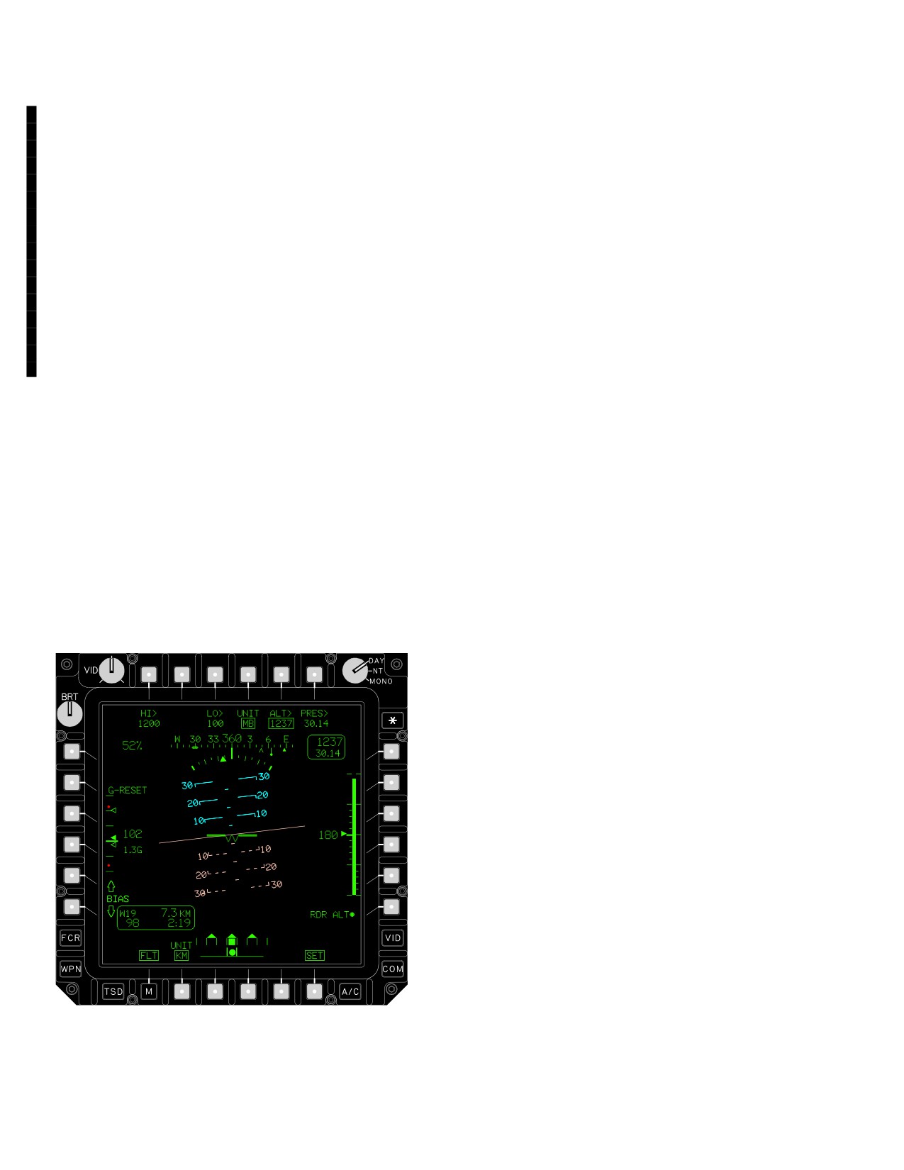
2.111 MPD FLT PAGE, FLT SET SELECTED
Radar Altitude HI indication. The HI button is presented if
the radar altimeter is on.
Selection of the FLT SET button presents the control but-
b. LO Button. The LO button displays and allows
tons necessary to configure the FLT page units of display,
editing of the altitude which triggers presentation of the
set the barometric altitude/pressure, set the criteria for
Radar Altitude LO indication and presentation of the audio
presentation of the HI and LO radar altitude indications,
message “altitude low”. No LO audio or visual indication is
power the radar altimeter, reset the accelerometer, apply
presented when LO is set to 0. The LO button is present-
a manual bias to the attitude indicator and HMD horizon
ed if the radar altimeter is 0.
line, and monitor symbols not continuously displayed on
c. UNIT IN/MB Button. The UNIT IN/MB button
the FLT Page when FLT SET is not selected.
sets the units of display for the barometric pressure digital
2.111.1 MPD FLT Page With FLT SET Selected But-
readout and the barometric PRES button. Barometric
tons. With the FLT SET button selected, (fig 2-99) the
pressure can be displayed in either inches of mercury
FLT Page provides the following button selections:
(“IN”) or millibars (“MB”).
d. ALT Button. The ALT button displays and al-
lows editing of the current barometric altitude. The baro-
metric altitude button is not presented if the ADS has
failed.
e. PRES Button. The PRES button displays and
allows editing of the current barometric pressure. Baro-
metric pressure data ranges from 28.10 to 30.99 in. of
mercury in 0.01 in. of mercury increments, or 951.5 to
1,049.4 mb in 0.1 mb increments. Changes in barometric
altitude are reflected in both barometric altitude and pres-
sure presentations. The barometric pressure is not pres-
ented if the ADS has failed.
f. G-RESET Button. The G-RESET button is dis-
played above the accelerometer. This function resets the
accelerometer tell-tales to 1 G.
g. Up and Down BIAS set buttons. The up BIAS
set button allows the air crew to add nose-up bias to the
pitch ladder and horizon line. The down BIAS set button
allows the air crew to add nose-down bias to the pitch lad-
der and horizon line. The up and down bias buttons can
apply as much as 10_ pitch offset in either direction. Typi-
LBA0801
cal uses of this control include applying a pitch offset, in
increments of 1_, to the attitude indicator and HMD hori-
Figure
2-99. FLT Page, FLT SET Selected
zon line’s EGI setting prior to takeoff.
Use or disclosure of this information is subject to the restriction(s) on the title page of this document.
2-104
Change 4
TM 1-1520-251-10
It can also be used while in flight to add an additional bias
1. Barometric Pressure and Status Win-
to the pitch ladder and horizon line after the attitude indi-
dow. Barometric pressure is presented in the upper right
cator has been aligned to the waterline. The bias applied
area of the page. Total range of barometric pressure is
can be cleared by deselecting the waterline button. When
28.10 to 30.99 in. of mercury in 0.01 in. of mercury incre-
a bias has been applied, a BIAS data field is presented on
ments, or 951.57 to 1,409.44 mB in 0.1 mB increments.
the FLT page below the - W - button (FLT SET not se-
When FLT SET is selected, the barometric pressure and al-
lected), or between the up and down BIAS buttons (FLT
titude are presented surrounded by a status window. Baro-
SET selected). These buttons are not presented when the
metric pressure is not presented unless the ADS finds its
EGI altitude data is not valid.
pressure altitudes to be valid and within valid range.
h. RAD ALT Button. The RAD ALT on/off button
2. G Status. The G status digital readout is pres-
provides the crew the ability to power the radar altimeter.
ented continuously when FLT SET is selected, rather than
The system default is ON for normal operations or ground
only when within 1/4 G of the dynamic limit. The G status is
power interruptions. The system will store the last status
not presented if acceleration data is not available from the
setting and return the radar altimeter to that state in the
EGI. See also para 2.110.2.23.
event of in-flight power interruption.
3. Accelerometer. The accelerometer is dis-
i. UNIT KM/NM button. The UNIT KM/NM button
played in the middle of the display format left of the air-
is presented below the navigation data status window,
speed digital readout. It has six components: indicated ac-
and sets the units for display of distance to go and for the
celeration, positive acceleration tell-tale, negative
TSD between KM and NM.
acceleration tell-tale, positive acceleration limit, negative
j. FLT SET button. Selection of the FLT SET but-
acceleration limit, and scale tic marks. A dynamic solid
ton presents the control buttons necessary to set or enter
triangle is provided to indicate the total G forces that the air-
data on the FLT page
craft is currently experiencing. When the current accelera-
k. FLT page button (on second level FLT page
tion exceeds a limit, the triangle is RED. The displayed
only). Pressing the FLT page button returns the MPD to
range is - 1 G to +4 Gs. As this vertical tape moves in a posi-
the top-level format.
tive or negative direction along the scale, it leaves “tell-tale”
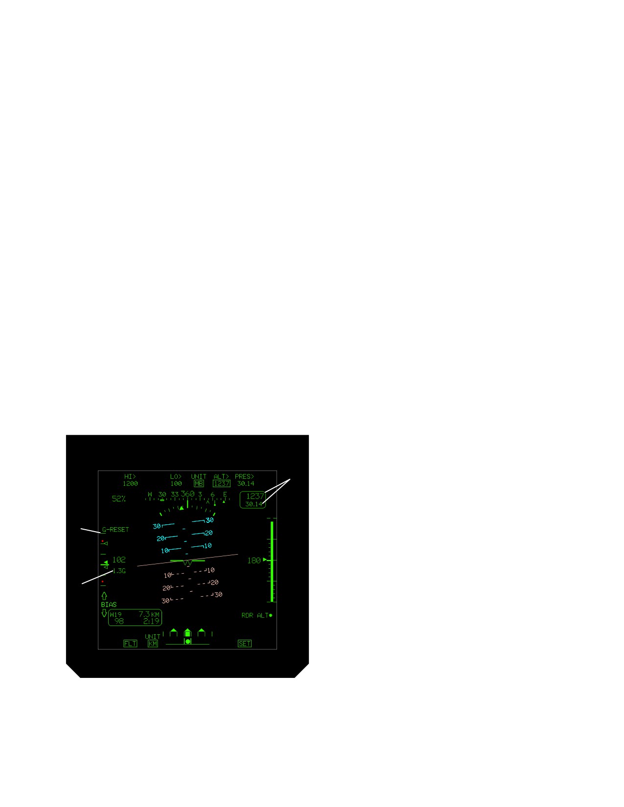
2.111.2 MPD FLT Page With FLT SET Selected Graph-
open triangles at the extreme points of its movement as an
ics. The FLT (Flight Instruments) Page, provides the
indication of recent G forces. When the tell - tale accelera-
symbols shown on the FLT page (fig 2-96), and the follow-
tion exceeded a limit, it is shown as RED. The tell-tale
ing additional graphics (fig 2-100):
triangle positions and colors are reset to 1 G and GREEN
by the accelerometer reset button. The upper and lower G
force limits, shown as RED dots on the scale, are devel-
oped from the flight envelope based on aircraft airspeed
and gross weight. If acceleration data is not available from
1
the INU, the symbol is not displayed.
2.112 STANDBY FLIGHT INSTRUMENTS (PILOT
STATION ONLY)
3
The pilot standby flight instruments directly measure and
provide independent backup displays of aircraft flight per-
formance (altitude, airspeed, attitude, and compass head-
ing) in case of primary power or flight reference system
failure. The standby flight instruments receive 28 Vdc
2
from the emergency dc bus.
LBA0801A
Figure 2-100. FLT Page Symbols
Use or disclosure of this information is subject to the restriction(s) on the title page of this document.
Change 4
2-105
TM 1-1520-251-10
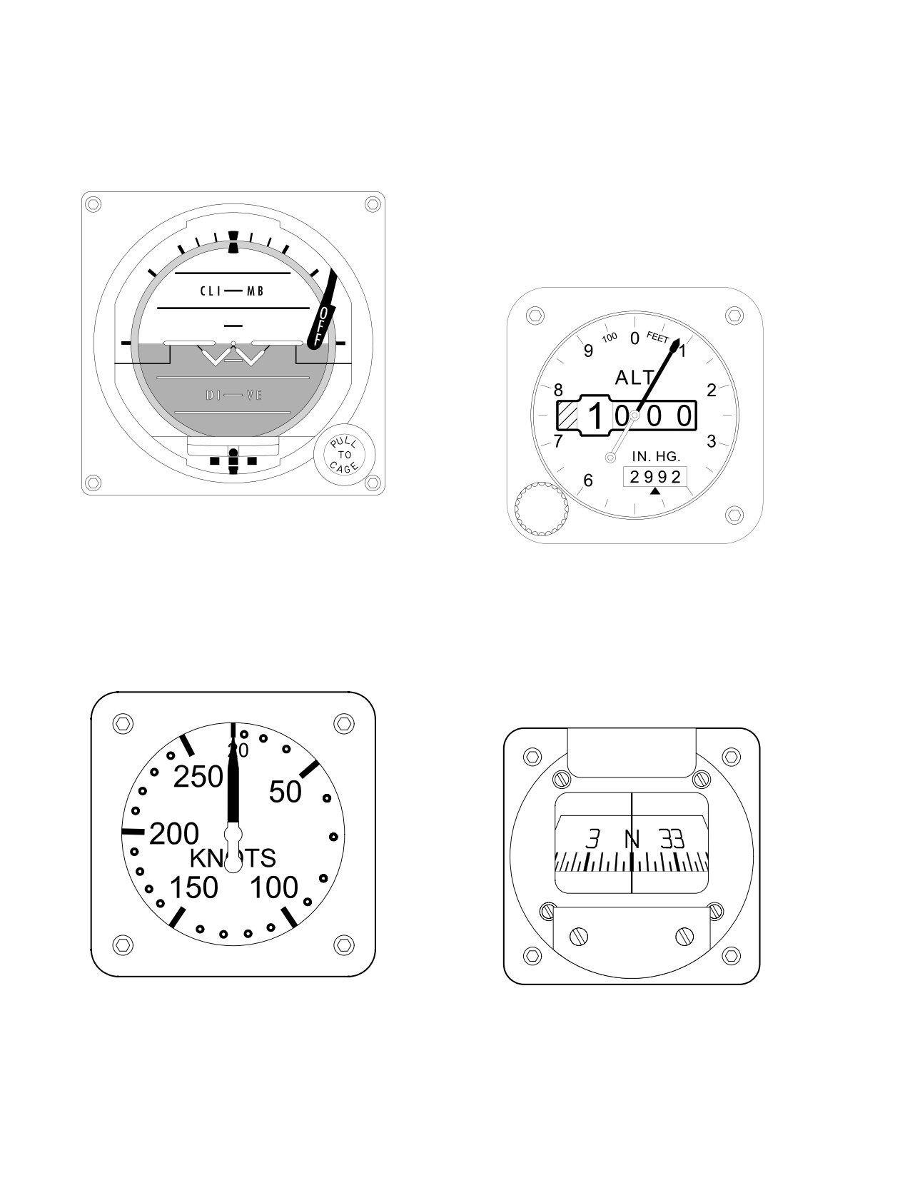
2.112.1 Standby Attitude Indicator. The standby atti-
2.112.3 Standby Altimeter. The standby altimeter in-
tude indicator (fig 2-101) displays helicopter attitude. The
dicator (fig 2-103) is graduated in 50 ft increments marked
indicator can display 360° of roll and "
85° of pitch.
at 100 ft intervals (0 - 9 x 100). Just left of center is a 1000
ft drum and a 10,000 ft drum to supplement the scale
pointer. The scale window in the lower right of the instru-
ment face, indicates barometric pressure setting in inches
of mercury. It is adjustable by use of the barometric pres-
sure set knob on the lower left corner of the indicator case.
Maximum allowable error is 70 ft.
LBA0664
Figure 2-101. Standby Attitude Indicator
LBA0078
Figure 2-103. Standby Altimeter
2.112.2 Standby Airspeed Indicator. The standby air-
speed indicator (fig 2-102) presents indicated airspeed (0
2.112.4 Standby Magnetic Compass. The standby
- 250 kts) from the right pitot probe.
magnetic compass (fig 2-104) is attached to the pilot gla-
reshield just left of center. A correction card is mounted
under the compass.
LBA0077
LBA0665
Figure 2-102. Standby Airspeed Indicator
Figure 2-104. Standby Magnetic Compass
Use or disclosure of this information is subject to the restriction(s) on the title page of this document.
2-106
TM 1-1520-251-10
Section XV. SERVICING, PARKING, AND MOORING
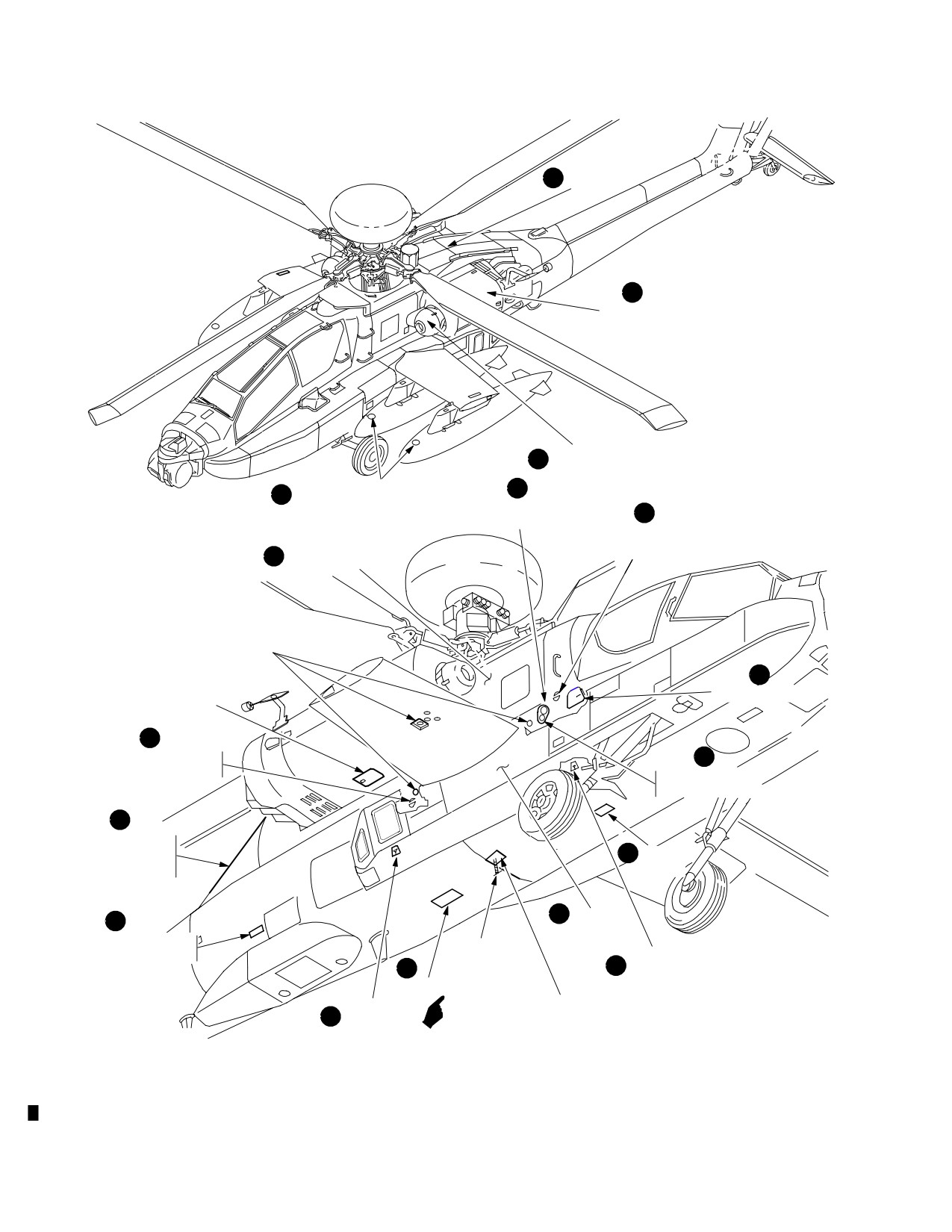
2.113 SERVICING
• Emergency fuels - None authorized.
Servicing information and procedures for the various sys-
2.113.3 Use of Fuels. There are special limitation on
tems or components are covered in the following para-
the use of commercial fuels (Table 2-10). For the purpose
graphs. Servicing points for fuel, engine oil, main trans-
of recording, fuel mixtures shall be identified by the major
mission, nose gearbox, and auxiliary power unit oil (fig
component of the mixture.
2-105). Fuel, lubricants, specifications, and fuel capacities
are listed in Table 2-9.
2.113.4
Interchangeable Fuels. Fuels having the
same NATO code number are interchangeable. Jet fuels
2.113.1 External Hydraulic, Pressurized Air and Elec-
(Table 2-10) conforming to specification ASTM D-1655
trical Requirements.
may be used when MIL-T-5624 fuels are not available. In-
terchanging fuel may change engine operating character-
a. External Hydraulic Power Requirements. Ex-
istics under the following circumstance.
ternal hydraulic power requirements are 3000 PSI at a
flow rate of 6 GPM for both the Primary and Utility hydrau-
a. NATO F-40 Fuel. Aircraft using NATO F-40
lic systems.
(JP-4) may be refueled with NATO F-44 (JP-5) or com-
mercial ASTM type A fuels. The engine operating charac-
b. External Pressurized Air Requirements. An
teristics may change because of lower operating tempera-
external air source that provides 40 psig and 30 lb per
tures. Slower acceleration, lower engine speed, harder
minute (300 cfm) air flow is required to pressurize the sys-
starting, and greater range may be experienced.
tem for engine start.
b. NATO F-44 Fuel. Aircraft using NATO F-44
(JP-5) may be refueled with NATO F-40 (JP-4) or com-
CAUTION
mercial ASTM type B fuels. The engine operating charac-
teristics may change because of higher operating temper-
28 Vdc from an external power source is not
atures. Faster acceleration, higher engine speed, easier
required in order to apply 115/200 Vac to the
starting, and less range may be experienced.
helicopter. If 28 Vdc is applied from the ex-
ternal power source, damage to the helicop-
c. NATO F-34 Fuel. NATO F-34 (JP-8) is almost
ter may occur. Prior to applying external
identical to commercial ASTM type A-1 fuels, but with a
electrical power, it must be confirmed that
corrosion inhibitor/lubricity improver and fuel system icing
pins E and F of the external power cable do
inhibitor additives.
not have 28 Vdc and that they are jumpered.
Pins E and F must be jumpered in order to
apply external electrical power to the heli-
2.113.5 Mixing of Fuels. When changing from one
copter.
type of authorized fuel to another, for example: JP-4 to
JP-5 it is not necessary to drain the fuel system before
c. External Electrical Power Requirements. Ex-
adding new fuel.
ternal electrical power requirements are 115/200 Vac, 400
Hz, and 45 KVA.
2.113.6 Oil Types. Oils are classified as primary, com-
mercial equivalent, or emergency as follows:
2.113.2 Fuel Types. Fuels are classified as primary,
commercial equivalent, or emergency, as follows:
• Primary oils are found in Table 2-11.
• Primary fuels are JP-4, JP-5, and JP-8.
• Commercial equivalent oils are found in Table
2-11.
• Commercial equivalent fuels are found in Table
2-10.
• Emergency oils - None authorized.
Use or disclosure of this information is subject to the restriction(s) on the title page of this document.
Change 1
2-107
TM 1-1520-251-10
D APU OIL
C
ENGINE OIL
(2 PLACES)
A NOSE GEARBOX OIL
(2 PLACES)
FUEL SERVICING, GRAVITY
K
N
METHOD AUXILIARY TANKS
FUEL SERVICING,
H
SINGLE POINT
FUEL SERVICING, GRAVITY
METHODFWD TANK
MAIN TRANSMISSION
B
REFUELING GROUND POINT
G
REFUELING PANEL
APU SIGHT GAGE
I
FUEL SERVICING, GRAVITY
J
METHODAFT TANK
FUEL SERVICING,
CLOSED CIRCUIT
E
PRIMARY/UTILITY
HYDRAULIC SYSTEMS
M
SUMP
SERVICING
DRAIN
O
F
BATTERY
COMPARTMENT
EXTERNAL ELECTRICAL
FUEL QTY
POWER RECEPTACLE
SUMP DRAIN
INDICATING
M
L
PLUNGER
TAPE
SUMP DRAIN
IAFS SUMP
SUMP DRAIN
L
DRAIN
PLUNGER
LBA0103
Figure 2-105. Servicing Diagram (Sheet 1 of 5)
Use or disclosure of this information is subject to the restriction(s) on the title page of this document.
2-108
Change 1
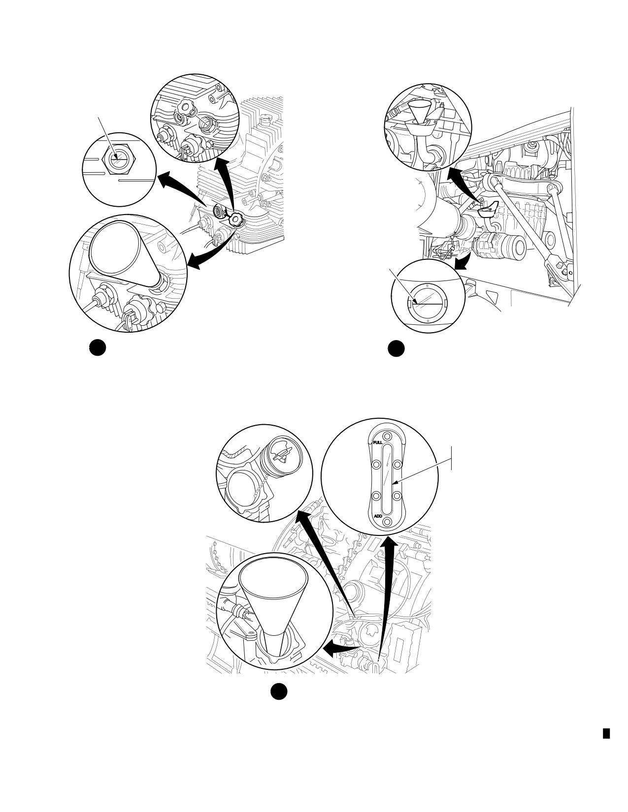
TM 1-1520-251-10
OIL LEVEL FULL
SIGHT GAGE
FUNNEL
OIL LEVEL FULL
BOTH SIDES
SIGHT GAGE
A
OIL SERVICINGENGINE NOSE GEARBOX
B OIL SERVICINGMAIN TRANSMISSION
OIL LEVEL FULL
WHEN SIGHT
GLASS FILLED
SIGHT
GAGE
FUNNEL
C OIL SERVICINGENGINE
M010932
Figure 2-105. Servicing Diagram (Sheet 2 of 5)
Use or disclosure of this information is subject to the restriction(s) on the title page of this document.
Change 1
2-109
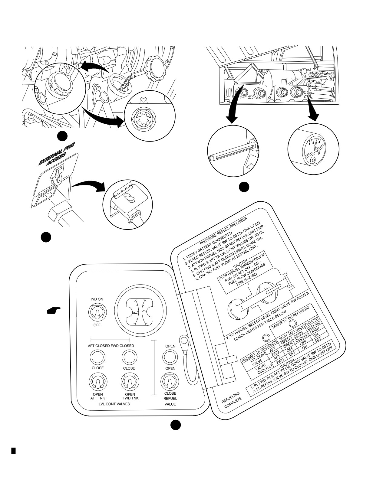
TM 1-1520-251-10
SIGHT
GAGE
D OIL SERVICING APU
E
FLUID SERVICINGHYDRAULIC
F
EXTERNAL POWER RECEPTACLE
FUEL QTY
FUEL
F
F
AFT
FWD
E
E
QTY
G
REFUELING PANEL
LBA2534
Figure 2-105. Servicing Diagram (Sheet 3 of 5)
Use or disclosure of this information is subject to the restriction(s) on the title page of this document.
2-110
Change 1
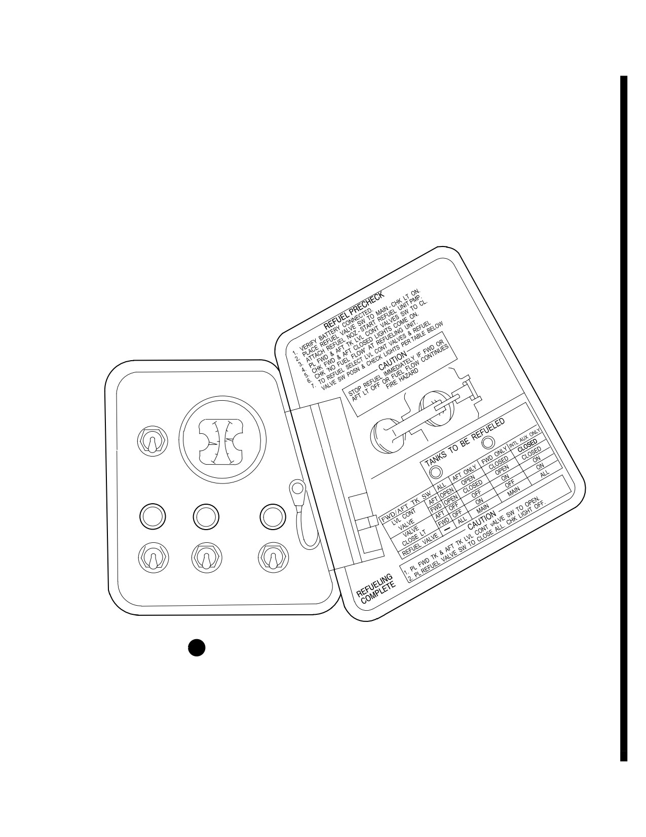
TM 1-1520-251-10
FUEL QTY
FUEL
IND ON
F
F
AFT
FWD
E
E
OFF
QTY
AFT CLOSED
FWD CLOSED
OPEN
CLOSED
CLOSED
ALL
MAIN
OPEN
OPEN
CLOSE ALL
AFT
FWD TANK
REFUEL
TANK
VALVE
G REFUELING PANEL (INTERNAL AUXILIARY FUEL SYSTEM)
LBA5025
Figure 2-105. Servicing Diagram (Sheet 4 of 5)
Use or disclosure of this information is subject to the restriction(s) on the title page of this document.
Change 1
2-110.1
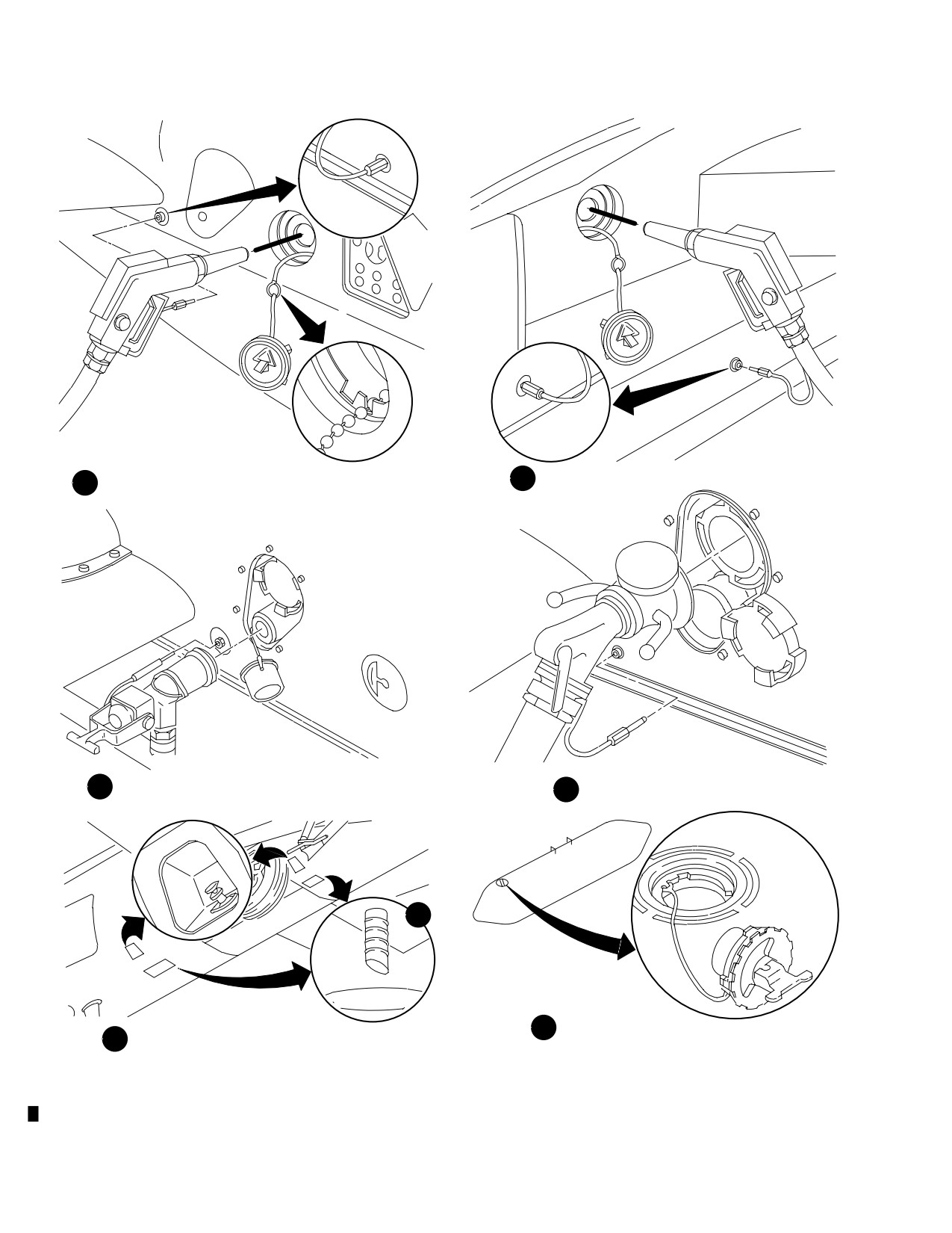
TM 1-1520-251-10
FUEL SERVICING, GRAVITY METHODFWD TANK
I FUEL SERVICING, GRAVITY METHOD AFT TANK
H
J
FUEL SERVICING, CLOSED CIRCUIT
K
FUEL SERVICING, SINGLE POINT
M
FUEL SERVICING
FUEL SUMP, DRAINS, AND
N
GRAVITY METHODEXTERNAL TANK
L
PLUNGER
LBA2535
Figure 2-105. Servicing Diagram (Sheet 5 of 5)
Use or disclosure of this information is subject to the restriction(s) on the title page of this document.
2-110.2
Change 1
TM 1-1520-251-10
Table
2-9. Fuel and Lubricant Specifications and Capacities
Tank or
Capacity
Materials
System
US
Name
Spec
Grade
Forward Fuel Cell
156 gal usable
Turbine Fuel
MIL-T-5624
JP-4
156 gal total
MIL-T-5624*
JP-5
MIL-T-83133
JP-8
Aft Fuel Cell
219 gal usable
Turbine Fuel
MIL-T-5624
JP-4
220 gal total
MIL-T-5624*
JP-5
MIL-T-83133
JP-8
Auxiliary Fuel Tank
229 gal usable
Turbine Fuel
MIL-T-5624
JP-4
230 gal total
MIL-T-5624*
JP-5
(each tank)
MIL-T-83133
JP-8
Internal Auxiliary Fuel System
129 gal usable
Turbine Fuel
MIL-T-5624
JP-4
130 gal total
MIL-T-5624*
JP-5
MIL-T-83133
JP-8
IAFS Combo - Pak
98 gal usable
Turbine Fuel
MIL-T-5624
JP-4
100 gal total
MIL-T-5624*
JP-5
MIL-T-83133
JP-8
Engine Oil
7 qt
Lubricating Oil
MIL-L-23699*
MIL-L-7808
Main Transmission
45 pt (22.5 qt)
Lubricating Oil
MIL-L-23699*
MIL-L-7808
Engine Nose Gearbox
5 pt (2.5 qt)
Lubricating Oil
MIL-L-23699*
(each gearbox)
MIL-L-7808
Intermediate Gearbox
2 lb, 2 oz
Grease, SYN-Tech
HMS 20-1155
NS 4405 FG
Tail Rotor Gearbox
3 lb, 5 oz
Grease, SYN-Tech
HMS 20-1155
NS 4405 FG
Auxiliary Power Unit (APU)
2 qt
Lubricating Oil
MIL-L-23699*
MIL-L-7808
Primary Hydraulic System
3 qt
Hydraulic Fluid
MIL-H-83282*
MIL-H-5606
Utility Hydraulic System
2.6 gal
Hydraulic Fluid
MIL-H-83282*
MIL-H-5606
Main Landing Gear Shock
3.8 qt
Hydraulic Fluid
MIL-H-5606
Strut
Nitrogen
Tail Landing Gear Shock Strut
Hydraulic Fluid
MIL-H-5606
Nitrogen
Brake System
0.32 gal
Hydraulic Fluid
MIL-H-5606
Engine Air Turbine Starter
0.422 pt
Lubricating Oil
MIL-L-23699*
MIL-L-7808
* Use in ambient temperatures of - 25 ° F ( - 32 °C) and above.
Do not mix lubricating oils MIL-L-23699 and MIL-L-7808.
Do not mix hydraulic fluids MIL-H-83282 and MIL-H-5606.
(2-111 blank)/2-112
Change 2
TM 1-1520-251-10
Table 2-10. Approved Fuels
US Military Fuel
JP-4 (MIL-T-5624)
JP-5 (MIL-T-5624) or JP-8 (MIL-T-83133)
NATO Code No.
F-40 (Wide Cut Type)
F-44 or F-34 (High Flash Type)
COMMERCIAL FUEL
JET A-1
(ASTM-D-1655)
JET B
JET A
NATO F-34
American Oil Co.
American JP-4
American Type A
Atlantic Richfield
Arcojet B
Arcojet A
Arcojet A-1
Richfield Div
Richfield A
Richfield A-1
B.P. Trading
B.P.A.T.G.
B.P.A.T.K.
Caltex Petroleum Corp.
Caltex Jet B
Caltex Jet A-1
Cities Service Co.
CITGO A
Continental Oil Co.
Conoco JP-4
Conoco Jet-50
Conoco Jet-60
Gulf Oil
Gulf Jet B
Gulf Jet A
Gulf Jet A-1
EXXON Co. USA
EXXON Turbo Fuel B
EXXON A
EXXON A-1
Mobil Oil
Mobil Jet B
Mobil Jet A
Mobil Jet A-1
Phillips Petroleum
Philjet JP-4
Philjet A-50
Shell Oil
Aeroshell JP-4
Aeroshell 640
Aeroshell 650
Sinclair
Superjet A
Superjet A-1
Standard Oil Co.
Jet A. Kerosene
Jet A-1 Kerosene
Chevron
Chevron B
Chevron A-50
Chevron A-1
Texaco
Texaco Avjet B
Avjet A
Avjet A-1
Union Oil
Union JP-4
76 Turbine Fuel
Belgium
BA-PF-2B
Canada
3GP-22F
3-6P-20x20
Denmark
JP-4 MIL-T-5624
France
Air 3407A
Germany
VTL-9130-006
UTL-9130-0007/UTL 9130-010
Greece
JP-4 MIL-T-5624
Italy
AA-M-C-1421
AMC-143
Netherlands
JP-4 MIL-T-5624
D ENG RD 2493
Norway
JP-4 MIL-T-5624
Portugal
JP-4 MIL-T-5624
Turkey
JP-4 MIL-T-5624
United Kingdom (Britain)
D. Eng RD 2454
D.Eng RD 2498
NOTE: COMMERCIAL FUEL LIMITATIONS
Anti-icing and Biocidal Additive for Commercial Turbine Engine Fuel. The additive provides anti-icing protection
and functions as a biocide to kill microbial growths in aircraft fuel systems. Icing inhibitor conforming to
MIL-I-27686 shall be added to commercial fuel, not containing an icing inhibitor, during refueling operations, re-
gardless of ambient temperatures. Refueling operations shall be accomplished in accordance with accepted
commercial procedures. This additive (Prist or equivalent.) is not available thru the Army Supply System, but is
to be locally procured when needed.
Use or disclosure of this information is subject to the restriction(s) on the title page of this document.
2-113
TM 1-1520-251-10
Table 2-11. Approved Oils
Approved Domestic Commercial Oils for MIL-L-7808
Manufacturer’s Name
Manufacturer’s Designation
American Oil and Supply Co.
PQ Turbine Oil 8365
Humble Oil and Refining Co.
ESSO/ENCO Turbo Oil 2389
Mobile Oil Corp.
RM-184A/RM-201A
Approved Domestic Commercial Oils for MIL-L-23699
Manufacturer’s Name
Manufacturer’s Designation
Americal Oil and Supply Co.
PQ Turbine Lubricant 5247/
6423/6700/7731/8878/9595
Bray Oil Co.
Brayco 899/899-G/899-S
Castrol Oil Co.
Castrol 205
Chevron International Oil Co., Inc.
Jet Engine Oil 5
Crew Chemical Corp.
STO-21919/STO-21919A/STD 6530
W.R. Grace and Co. (Hatco Chemical Div.)
HATCOL 3211/3611
Humble Oil and Refining Co.
Turbo Oil 2380 (WS-6000)/2395
(WS-6495)/2392/2393
Mobile Oil Corp.
RM-139A/RM-147A/Avrex S
Turbo 260/Avrex S Turbo 265
Royal Lubricants Co.
Royco 899 (C-915)/899SC/
Stauffer Jet II
Shell Oil Co., Inc.
Aeroshell Turbine Oil 500
Shell International Petroleum Co., Ltd.
Aeroshell Turbine Oil 550
Standard Oil Co., of California
Chevron Jet Engine Oil 5
Stauffer Chemical Co.
Stauffer 6924/Jet II
Texaco, Inc.
SATO 7377/7730 TL-8090
Approved Foreign Commercial Oils for MIL-L-7808
Data not available at this time.
Approved Foreign Commercial Oils for MIL-L-23699
Data not available at this time.
Use or disclosure of this information is subject to the restriction(s) on the title page of this document.
2-114
TM 1-1520-251-10
2.114 FUEL SYSTEM SERVICING
2.114.3 Single-Point Adapter (SPA) Pressure Refuel-
ing.
Each fuel cell is serviced through gravity filler receptacles
or is pressure filled through closed circuit or single point
CAUTION
adapters (fig 2-105 sheet 4 of 4). Table 2-9 lists individual
tank capacities.
Refueling pressure will not exceed 55 lb/
psig. Damage to fuel system may result.
2.114.1 Gravity Refueling.
Using servicing instruction printed on the inside panel of
the refuel panel access door (fig 2-105 sheet 3 of 4), per-
form pressure refueling pre-check. Remove adapter cap,
and using a standard US Army supplied SPA nozzle, fill
WARNING
fuel cells with correct fuel to the required level (Table 2-9).
With the SPA nozzle, fuel flow at 50 psi is at least 100
gpm.
When opening anti-syphoning device on
external tank flapper valve, extreme care
NOTE
should be exercised when releasing air
Auxiliary fuel quantity must be added
pressure to preclude venting of fuel
through AUX GALLONS data entry button
overboard through the filler neck.
on the FUEL page
2.114.4 Refueling of External Auxiliary Tanks. The
CAUTION
external auxiliary tanks are gravity filled through filler re-
ceptacles. Remove the gravity filler caps and service
tanks with correct fuel to the required levels (Table 2-9).
To prevent damage to fuel system, do
not exceed maximum fueling pressure of
2.114.4A Refueling of Internal Auxiliary Fuel System
15 psi.
(IAFS). The IAFS can only be pressure refueled using
the Closed - circuit or Single Point adapter. Basic proce-
dures are the same as for refueling the main cells (para
For gravity refueling, open fuel vent shutoff valve, remove
2.114.2 and 2.114.3). The IAFS can be refueled separate-
filler cap, pull chain (opening anti-syphoning device), and
ly from, or together with, the main fuel cells. Configure the
using correct fuel, service fuel cells to the required levels
switches in the refueling panel to refuel the desired cells
(Table 2-9).
(see refueling panel decal) and refuel using normal proce-
dures.
2.114.2 Closed-Circuit Pressure Refueling.
2.114.5 Fuel Sump Drains. Two fuel sump drains, one
for each internal fuel tank, are located on the underside of
the fuselage. These drains are used to drain fuel or water
CAUTION
and to check for fuel contamination. To actuate, press the
plunger. Hold until sufficient fuel has drained.
Refueling pressure will not exceed 55 lb/
2.114.5A IAFS Sump Drains. The IAFS is equipped
psig. Damage to fuel system may result.
with a sump drain used for draining fuel or water or to test
for contamination. This is accessed by opening the IAFS
sump access door located at the bottom of the ammo bay
Using service instructions printed on the inside panel of
cover. To activate, press the plunger until sufficient fuel
the refuel panel access door (fig 2-105 sheet 3 of 4), per-
has drained.
form pressure refueling pre-check. Remove adapter cap,
and using a standard US Army nozzle, service fuel cells
2.114.5B Fuel Quantity Indicating Tape. The fuel
with the correct fuel to the required level (Table 2-9). Using
quantity indicating tape, located on aft center of the modi-
the standard US Army nozzle, fuel flow at 15 psi is 56 gal
fied ammunition bay door, is a mechanical indicator of the
per minute (gpm).
fuel quantity in the internal auxiliary fuel cell.
Use or disclosure of this information is subject to the restriction(s) on the title page of this document.
Change 1
2-115
TM 1-1520-251-10
2.114.6 Rapid Refueling. The helicopter can be refueled
4. A/S switch - SAFE
for rapid turnaround using one of the following procedures:
5. APU - Start
• Warm refueling with both engines shut down, rotor
6. Engine PWR levers - IDLE for 2 minutes, then
stopped, and APU running.
OFF.
• Hot refueling with engine 2 shutdown and rotors
7. IDM auto transmit - Disable
turning.
a. SET page IDM INHBT - Select, IDM IN-
• Hot refueling using the D1 nozzle with both
HIBIT advisory boxed
engines operating and rotors turning.
or
BLK 1
perform b,c, and d
The following additional procedures shall be observed for
rapid refueling:
b. AUTO REPLY - Off
c. AUTO ACK - Off
CAUTION
d. TACFIRE Net - Not tuned.
• Pilot and CPG shall perform their arma-
NOTE
ment safety checks prior to entering the
When selected, the IDM INHBT button is
Forward Area Refueling Point (FARP).
continuously displayed as Operation In
• Radio transmissions (automated or
Progress.
crew initiated) shall be limited to
8.
HF RADIO - Disable auto radio transmission
EMERGENCIES ONLY until refueling
capability
has been completed.
a. HF RADIO GND OVRD - Off.
• The IDM’s AUTO REPLY and AUTO
ACK shall be turned off
BLK 1
or the
or
IDM INHBT button shall be selected
b. HF RADIO SILENT - On.
BLK 2
9.
RTR BRK switch - BRK (below 50% NR until ro-
•
BLK 1
Aircrews shall ensure that
tor stopped, then OFF).
there are no actively tuned TACFIRE
10.
ANTI-COL switch - OFF.
nets prior to refuel/rearm.
11.
Refueling - Monitor.
• Prior to departure, ground personnel
shall advise the pilot that the fuel caps
12.
Refueling completed - Verify [
BLK 1
RE-
are installed and grounding cables are
FUEL VALVE ] or [
REFUEL VALVE
BLK 2
removed.
OPEN ] (UFD/EUFD) and REFUEL VALVE
OPEN (MPD) cautions are not displayed.
• Uncommanded FM transmissions may
occur during IDM IBIT, FALLBACK,
13.
IDM auto transmit capability - Set as required
when the CIU circuit breaker is open, or
a. SET page IDM INHBT - Deselect as re-
during CIU power-up. CIU power-up oc-
quired: IDM INHIBIT advisory is not dis-
curs during aircraft power-up and upon
played and IDM INHIBIT button is non OIP
CIU circuit breaker reset.
or
BLK 1
perform b,c, and d
NOTE
b. AUTO REPLY - Set as required
• There is no UFD/EUFDadvisory associated with
c. AUTO ACK - Set as required
the selection of the HF GND OVRD button.
d. TACFIRE Net - Set as required.
• The IDM INHBT button will not inhibit automated
HF radio transmissions
14.
HF RADIO - Set as required
a. HF RADIO GND OVRD - On or Off.
a. Rapid (Warm) Refueling. The following proce-
dures and steps shall be observed for warm refueling with
and/or
both engines shut down, rotor stopped, and APU running:
b. HF RADIO SILENT - On or Off.
1. TAIL WHEEL switch - LOCK.
15.
ANTI-COL switch - As Desired.
2. PARK BRAKE - Set.
16.
Engines Start - Perform appropriate STARTING
3. Weapons - Secure
ENGINES procedure.
Use or disclosure of this information is subject to the restriction(s) on the title page of this document.
2-116
Change 3
TM 1-1520-251-10
b. Rapid (HOT) Refueling. The following proce-
or
BLK 1
perform b,c, and d
dures and steps shall be observed for hot refueling with
b. AUTO REPLY - Set as required
engine 2 shut down and rotors turning or using the D1
c. AUTO ACK - Set as required
nozzle with both engines operating and rotors turning:
1. TAIL WHEEL switch - LOCK.
d. TACFIRE Net - Set as required
2. PARK BRAKE - Set.
12.
HF RADIO - Set as required
3. Weapons - Secure.
a. HF RADIO GND OVRD - On or Off.
4. A/S switch - SAFE.
and/or
5. Engine POWER levers - As required.
b. HF RADIO SILENT - On or Off
a. Both engines running and rotors turning -
13.
ANTI-COL switch - As Desired.
(1) POWER Lever NO 2 to IDLE.
14.
Collective - Apply until 60% torque (No 1 en-
(2) FUEL page XFER button - OFF.
gine) is reached or aircraft is light on wheels.
or
Maintain power setting for 30 seconds.
b. Single engine and rotors turning - POWER
15.
CROSSFEED - NORM. Maintain power setting
Lever NO 2 to IDLE for 2 minutes, then OFF.
for 30 seconds.
6. IDM auto transmit - Disable
16.
Collective - Reduce to minimum torque.
17.
Engine POWER levers - As required.
a. SET page IDM INHBT - Select : IDM IN-
HIBIT advisory boxed
a. Both engines running and rotors turning -
(1) POWER Lever NO 2 to FLY.
or
BLK 1
perform b,c, and d
(2) FUEL page XFER button - AUTO.
b. AUTO REPLY - Off
or
c. AUTO ACK - Off
b. Single engine and rotors turning - Perform
appropriate engine 2 start. Use crossbleed
d. TACFIRE Net - Not tuned
procedure.
NOTE
NOTE
When selected, the IDM INHBT button is
There is an increased probability of engine
continuously displayed as Operation In
No.1 or No. 2 FUEL PSI LOW UFD/EUFD
Progress
message, master caution illumunation and
flame out due to non - use of the single en-
7. HF RADIO - Disable auto radio transmission
gine torque pull procedure. While the dual
capability
engine feed forward tank will not remove air
a. HF RADIO GND OVRD - Off.
from the ammunition bay feed line. Air accu-
mulation in the No. 1 engine fuel feed hose
or
is not affected.
b. HF RADIO SILENT - On
c. Rapid
(HOT) Refueling
(Sandy Environ-
8. ANTI-COL switch - OFF.
ment). The following procedures and steps shall be ob-
served for hot refueling in sandy environments with en-
9. Refueling - Monitor. When the aft tank is full -
gine 2 shut down and rotors turning or using the D1 nozzle
CROSSFEED - AFT. Continue to refuel the for-
with both engines operating and rotors turning:
ward tank.
1. TAIL WHEEL switch - LOCK.
10. Refueling completed - Verify [
BLK 1
RE-
FUEL VALVE ] or [
BLK 2
REFUEL VALVE
2. PARK BRAKE - Set.
OPEN ] (UFD/EUFD) and REFUEL VALVE
3. Weapons - Secure.
OPEN (MPD) cautions are not displayed.
4. A/S switch - SAFE.
11. IDM auto transmit capability - Set as required
5. Engine POWER levers - As required.
a. SET page IDM INHBT - Deselect as re-
a. Both engines running and rotors turning -
quired: IDM INHIBIT advisory is not dis-
(1) POWER Lever NO 2 to IDLE.
played and IDM INHIBIT button is non OIP
(2) FUEL page XFER button - OFF.
Use or disclosure of this information is subject to the restriction(s) on the title page of this document.
Change 3
2-116.1
TM 1-1520-251-10
or
b. AUTO REPLY - Set as required
b. Single engine and rotors turning - POWER
c. AUTO ACK - Set as required
Lever NO 2 to IDLE for 2 minutes, then OFF.
d. TACFIRE Net - Set as required
6. IDM auto transmit - Disable
12.
HF RADIO - Set as required
a. SET page IDM INHBT - Select : IDM IN-
a. HF RADIO GND OVRD - On or Off.
HIBIT advisory boxed
and/or
or
BLK 1
perform b,c, and d
b. HF RADIO SILENT - On or Off
b. AUTO REPLY - Off
13.
ANTI-COL switch - As Desired.
c. AUTO ACK - Off
14.
Engine POWER levers - As required.
d. TACFIRE Net - Not tuned
a. Both engines running and rotors turning -
NOTE
(1) POWER Lever NO 2 to FLY.
(2) FUEL page XFER button - AUTO.
When selected, the IDM INHBT button is
continuously displayed as Operation In
or
Progress
b. Single engine and rotors turning - APU
start. Engine 2 start. POWER Lever NO 2 to
7. HF RADIO - Disable auto radio transmission
FLY.
capability
15.
Collective - Reduce to minimum torque.
a. HF RADIO GND OVRD - Off.
16.
Switch CROSSFEED to FORWARD position so
or
that both engines feed from forward tank for 60
seconds.
b. HF RADIO SILENT - On
8. ANTI-COL switch - OFF.
17.
Switch CROSSFEED to NORMAL and wait 30
seconds.
9. Refueling - Monitor. When the aft tank is full -
CROSSFEED - AFT. Continue to refuel the for-
18.
After 30 seconds, switch CROSSFEED to AFT
ward tank.
and wait 60 seconds.
10. Refueling completed - Verify [
BLK 1
RE-
FUEL VALVE ] or [
BLK 2
REFUEL VALVE
19.
After 60 seconds, switch CROSSFEED to NOR-
OPEN ] (UFD/EUFD) and REFUEL VALVE
MAL and wait 30 seconds.
OPEN (MPD) cautions are not displayed.
2.115 ENGINE OIL SYSTEM SERVICING
11. IDM auto transmit capability - Set as required
The engine oil tank is located within the engine frame. It is
a. SET page IDM INHBT - Deselect as re-
serviced through a gravity filler port. An oil-level sight gage is
quired: IDM INHIBIT advisory is not dis-
located near the gravity filler port. When the oil level falls to
played and IDM INHIBIT button is non OIP
the add mark, replenish with the correct oil (Table 2-11) until
or
BLK 1
perform b,c, and d
the level reaches the full mark on the sight gauge.
Use or disclosure of this information is subject to the restriction(s) on the title page of this document.
2-116.2
Change 3
TM 1-1520-251-10
2.116 MAIN TRANSMISSION SERVICING
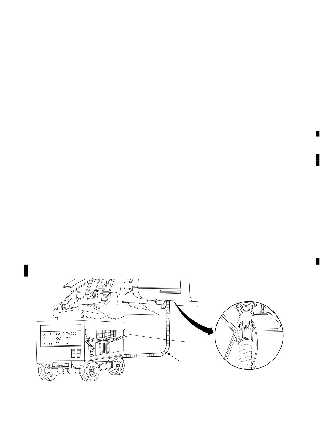
2.120 EXTERNAL PRESSURIZED AIR SOURCE
The main transmission is located below the main rotor
An external air receptacle (fig 2-106) under the No 1 en-
static mast base in the center fuselage section. Access to
gine nacelle provides an attachment point for an external
the oil filler cap and the right sump oil-level sight gage (fig
air line to start either engine or accomplish maintenance
2-105 sheet 2 of 4) is through the transmission access
functions. An external air source that provides 40 psig and
panel on the right side of the fuselage. The left sump oil
30 lb per minute air flow is required to pressurize the sys-
level sight gage can be viewed through the transmission
tem for engine start. The maximum pressure from a
access door on the left side of the fuselage. Add oil to the
ground source shall not exceed 50 psig.
proper service level. Table 2-11 lists the proper oil to use.
2.121 TOWING THE HELICOPTER
The proper level is an average between both left and right
sight glasses and should be one-half (1/2) full in the sight
Tow the helicopter by attaching a tow bar to the tail wheel
glass.
fork. Towing the helicopter must be accomplished by
trained personnel in accordance with instructions in TM
2.117 AUXILIARY POWER UNIT (APU) SERVICING
1-1520-Longbow/Apache.
The APU oil filler cap and oil level sight gage (fig 2-105
2.122 MOORING THE HELICOPTER
sheet 3 of 4) are located on the oil reservoir on the APU
gearbox. The oil level can be viewed through an access
The helicopter is moored IAW TM 1-1520-Longbow/
panel under the No 2 engine. Remove the oil filler cap and
Apache.
add oil until the oil level reaches the proper service level.
Table 2-11 lists the proper oil to use.
2.123 CANOPY AND WINDSHIELD CLEANING
2.118 NOSE GEARBOX SERVICING
The canopy and windshield should be carefully cleaned
with clear water and a moist chamois or paper cleaning
The engine nose gearboxes are mounted on the front of
towel. Grease or oil spots should be removed with a paper
each engine. When the oil falls below the proper service
cleaning towel moistened in an approved plastic cleaning
level, replenish with correct oil. Table 2-11 lists the correct
agent.
oil to use. Proper service level is oil filled to one-half of the
sight glass (fig 2-105 sheet 3 of 4).
2.124 TADS/PNVS SHROUD WINDOW CLEANING
TADS/PNVS shroud windows should be cleaned, using a
2.119 HYDRAULIC SYSTEM SERVICING
paper cleaning towel (lens paper preferred) moistened
with a solution of an approved mild detergent and clean
The hydraulic system should only be serviced with the ap-
water, followed by a clean water rinse. Special optics
proved fluids (Table 2-11). Detailed hydraulic system serv-
cleaning procedures (TM 1-1520-Longbow/Apache)
icing instructions are contained in TM 1-1520-Longbow/
should be used to clean the shroud windows as soon as
Apache.
practicable.
AIR HOSE
LBA0036
Figure 2-106. External Pressurized Air Receptacle
Use or disclosure of this information is subject to the restriction(s) on the title page of this document.
Change 2
2-117
TM 1-1520-251-10
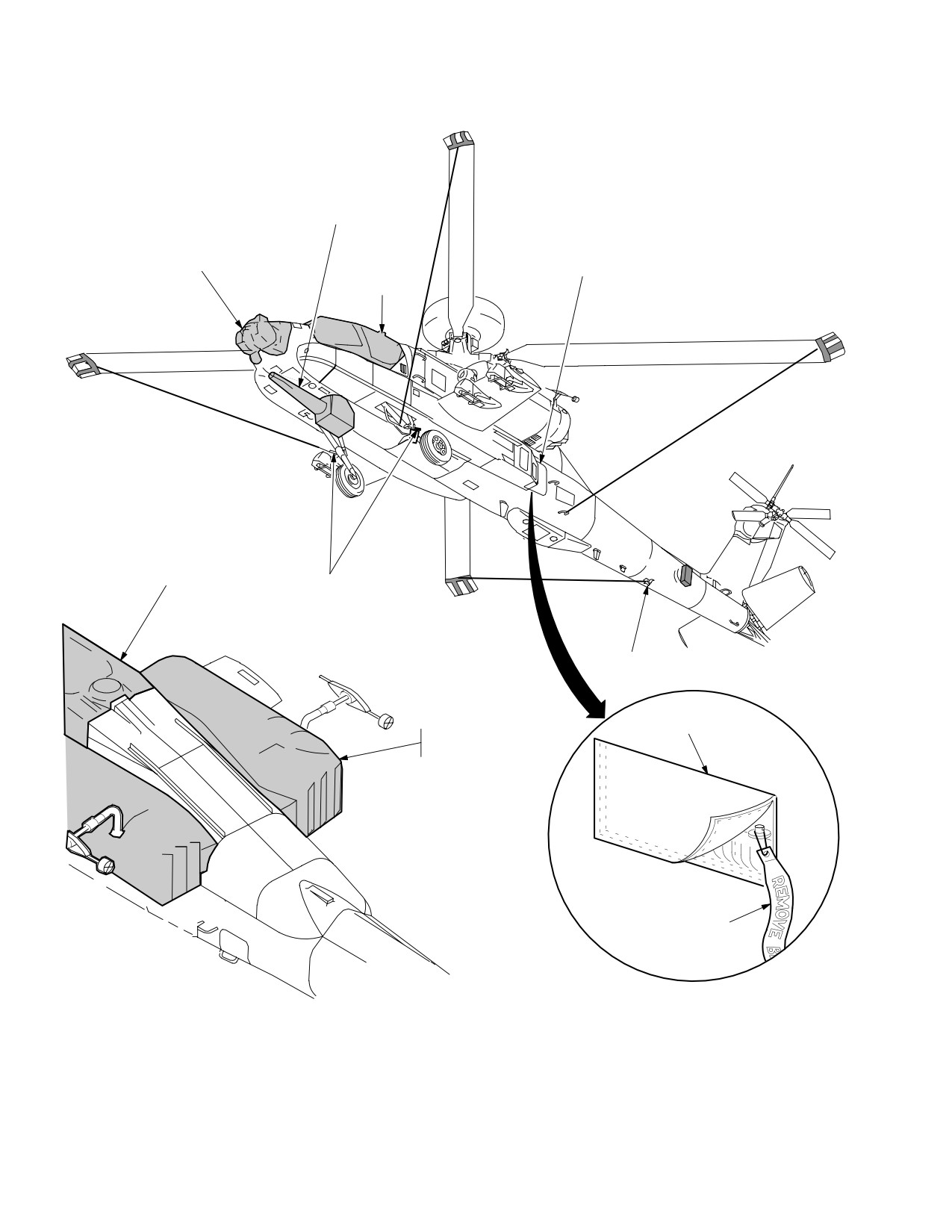
AREA WEAPON AND TURRET
PROTECTIVE COVER
TADS/PNVS
PROTECTIVE
FLYAWAY KIT
CANOPY
COVER
STOWAGE
PROTECTIVE
COVER
APERTUR
E COVER
MOORING LUG
(2 PLACES)
AFT FUSELAGE
TIE DOWN
SAFETY PINS
POUCH
ENGINE NACELLE
COVER (2 PLACES)
RED STREAMER
*UPPER FLIGHT CONTROLS AND ROTOR SYSTEM NOT SHOWN FOR CLARITY
LBA0038
Figure 2-107. Protective Covers, Mooring, and Towing Provisions (Sheet 1 of 2)
Use or disclosure of this information is subject to the restriction(s) on the title page of this document.
2-118
TM 1-1520-251-10
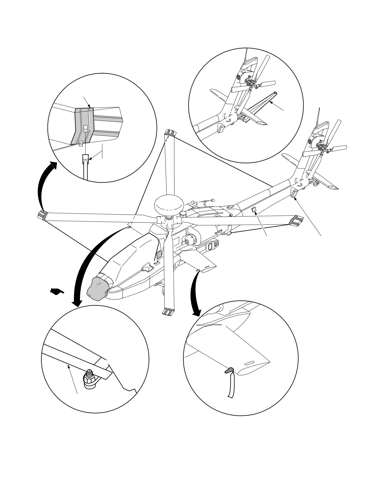
MAIN ROTOR BLADE
TIEDOWN ASSEMBLY
TOW
BAR
MAIN ROTOR BLADE
TIEDOWN POLE
ASSEMBLY
LASER WARNING
CHAFF DISPENSER
COVER
AND COVER
(4 PLACES)
(OPTIONAL EQUIP)
PITOT HEAD
PROTECTIVE
COVER
PYLON
TIE - DOWN ROPE
LBA0039A
Figure 2-107. Protective Covers, Mooring, and Towing Provisions (Sheet 2 of 2)
Use or disclosure of this information is subject to the restriction(s) on the title page of this document.
Change 3
2-119
TM 1-1520-251-10
Section XVI. DATA MANAGEMENT SYSTEM
2.125 INTRODUCTION
2.126.5 [
BLK 1
Data Transfer Unit (DTU). DTU is
the name given to the combination of the following hard-
This section describes the display formats and dedicated
ware:]
components associated with the operation of the Data
a.
[
BLK 1
Data Transfer Cartridge (DTC). The
Management System (DMS) as well as the location and
DTC is a solid state memory device that facilitates transfer
function of each component. The DMS displays are inte-
of data from the mission planning station to the aircraft via
grated into the following major components.
the Data Transfer Receptacle, described below. The DTC
2.126 DMS HARDWARE
has 256 Kilobytes of battery powered memory available.]
The DMS is made up of System Processors (SPs), Dis-
b.
[
BLK 1
Data Transfer Receptacle
play Processors (DPs), Weapons Processors (WPs), a
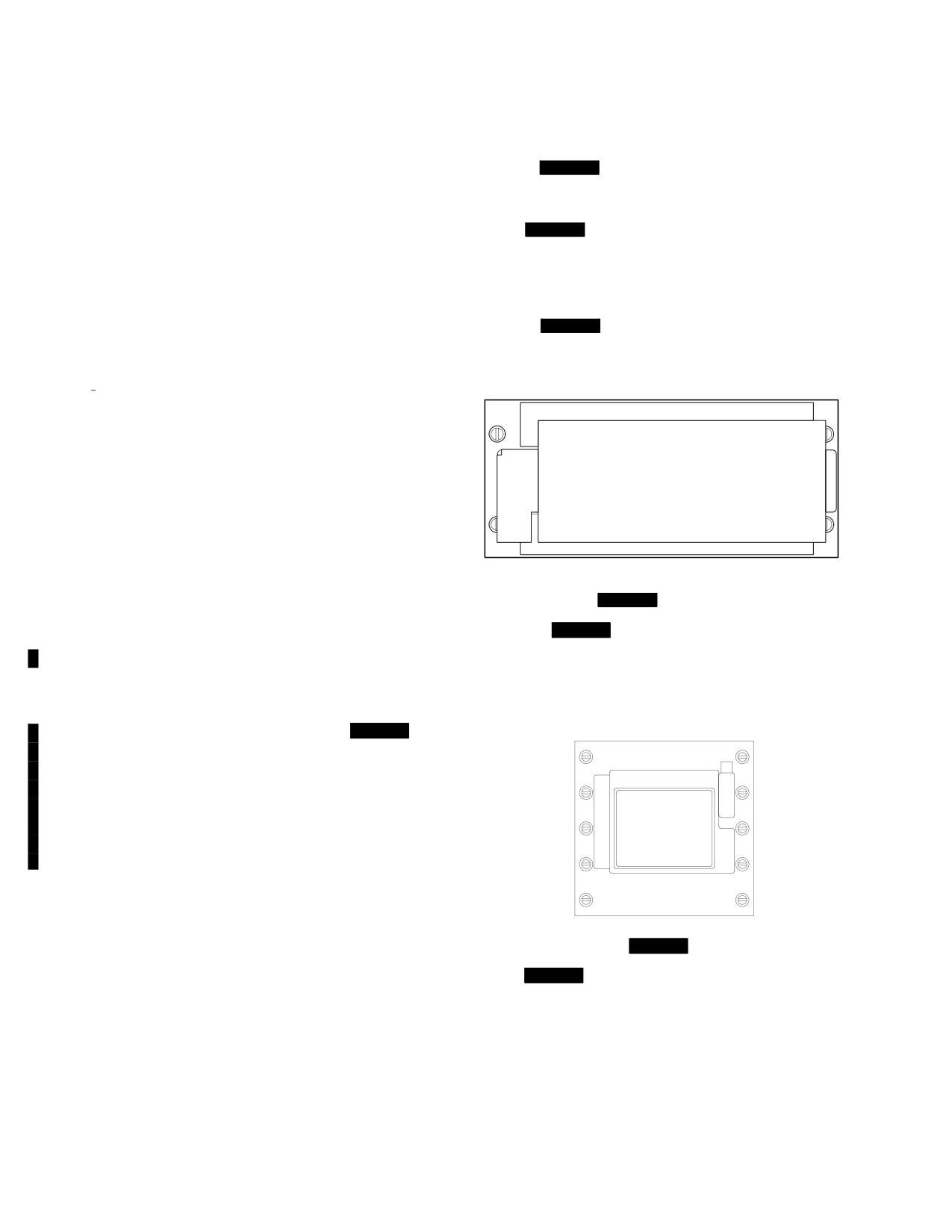
(DTR). The DTR (fig 2-108) accepts the DTC to facilitate
Communication Interface Unit (CIU), a Data Transfer Unit
uploading data from the DTC to selected LRUs and down-
(DTU), a Maintenance Data Recorder (MDR) and the off-
loading of aircraft information from the SP to the DTC.]
aircraft Aviation Mission Planning Station (AMPS).
2.126.1 System Processor (SP). The aircraft contains
two SPs. The SP commands all subsystem initiated tests,
monitors system status and fault information, and pro-
cesses the information for display. The SP provides air-
craft information to the DTU. There is a processor select
panel which provides a manual selection option. Non vol-
atile memory data exchange between SPs only occurs
when the SP Processor is in the AUTO position.
LBA1809
2.126.2 Display Processor (DP). There are two DPs,
Figure 2-108.
BLK 1
Data Transfer Receptacle
each of which controls two Multipurpose Displays (MPDs).
2.126.5A [
BLK 2
Data Transfer Unit (DTU). The
The DPs provide display information to the MPDs, Optical
DTU (fig 2-108A) is a four slot Personal Computer
Relay Tube (ORT) or TEDAC , VCR, and Integrated Helmet
Memory Card International Association (PCMCIA) inter-
and Display Sight System (IHADSS) displays. The DP also
face unit. The DTU will accept up to four type I, II, or III
processes keyboard, bezel button, and cursor inputs. The
DTCs. The DTU is connected directly to the DPs with two
DPs receive video recorder and sensor video signals and dis-
dedicated fibre channels. ]
tribute the signals to the appropriate display. [
BLK 2
The
DPs detect when one of the Color Image Processing Mod-
ules (CIPM) or the Monochrome Image Processing Modules
(MIPM) is not currently updating a particular display (MPDs,
IHADSS, ORT or TEDAC). If this occurs during dual DP op-
erations, the SP will allow the faulty DP to reset. This reset
will cause the crew to be in single DP operations, the reset
should last 13 to 24 seconds.]
2.126.3 Weapons Processor (WP). The aircraft con-
LBA5030
tains two WPs. The WPs command portions of weapons
subsystem initiated tests directly with the DPs, provides
Figure 2-108A.
BLK 2
Data Transfer Unit
system status and fault information to the SPs, and pro-
cesses that information for display.
a.
[
BLK 2
Data Transfer Card (DTC). The DTC
is a PCMCIA flash memory card that facilitates transfer of
2.126.4 Communication Interface Unit (CIU). The
data from the AMPS to the aircraft via the DTU. The DTC
CIU provides voice messages and tones for the Warnings,
can store up to two gigabytes of mission data and/or digi-
Cautions, and Advisories (WCA) subsystem.
tal maps.]
Use or disclosure of this information is subject to the restriction(s) on the title page of this document.
2-120
Change 3
TM 1-1520-251-10
2.126.6
Maintenance Data Recorder (MDR). The
2.127 DATA TRANSFER MANAGEMENT
MDR is a solid state memory device which provides crash
Crewmembers can select the type of data to be uploaded
survivable data storage for mishap investigation and en-
to the aircraft. The system processor will automatically
hanced aircraft maintenance. The MDR will store Flight
upload the saved status files to the aircraft after a power
Data, Maintenance Faults, Maintenance Excellences, and
failure has occurred. Selecting an upload function com-
WCAs. Operation of the MDR is automatic and requires
mands the system to retrieve specific data from the DTC
no crewmember interaction.
and upload them into the system memory for system or
mission operations. For data loading procedures see
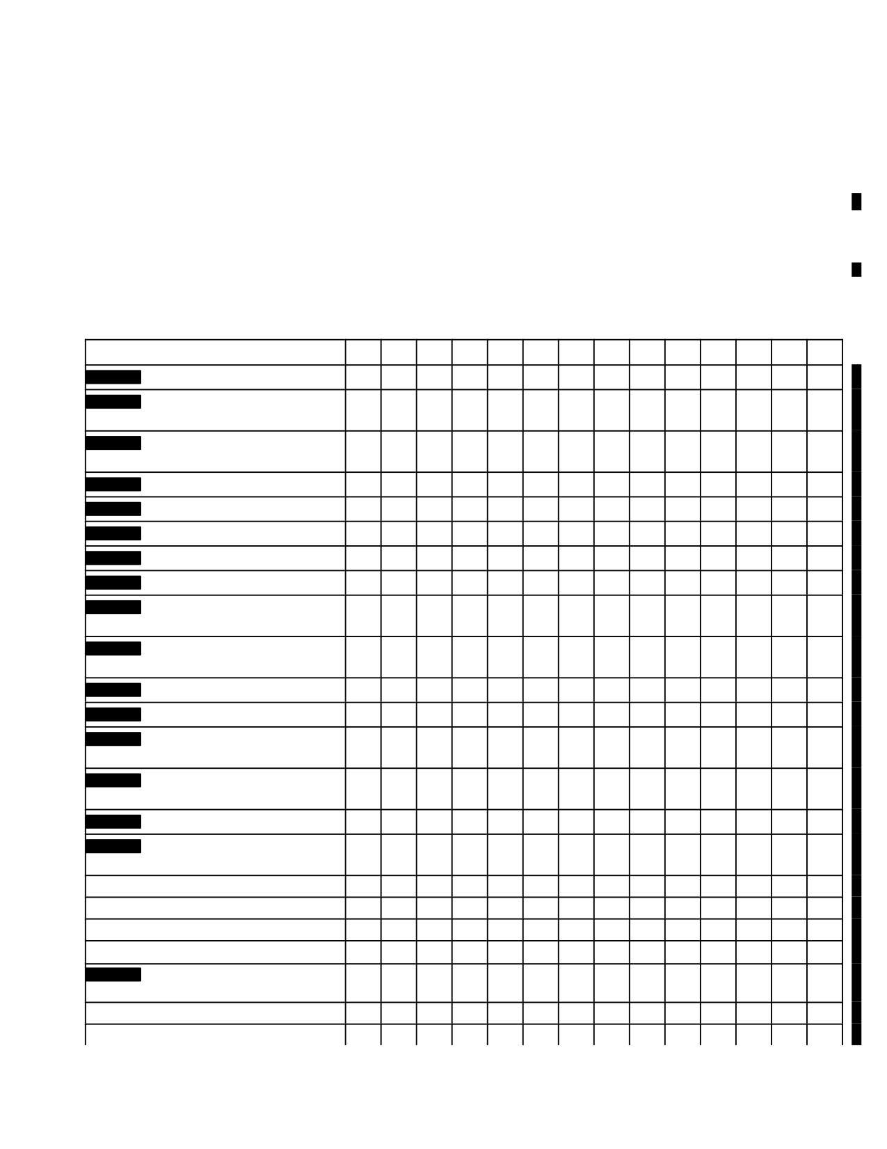
paragraph 2.129. Refer to Table 2-12 for DTC Upload
Data.
Table 2-12.
DTC Upload Data
Data to be Loaded*
A
B
C
D
E
F
G
H
I
J
K
L
M
N
BLK 1
IDM Free Text
X
X
BLK 1
IDM Tacfire Movement
X
X
Messages
BLK 1
IDM Tacfire Auto
X
X
Authentication
BLK 1
COMM Presets
X
X
BLK 1
COMM Preset Nets
X
X
BLK 1
Call Sign Frequencies
X
X
X
X
BLK 1
Authentication/Reply Codes
X
X
X
X
BLK 1
Transmit Authenticate Codes
X
X
X
X
BLK 1
IDM Subscribers Net
X
X
Assignments
BLK 1
IDM Auto Response Transmit
X
X
Flag
BLK 1
IDM Protocol Address
X
X
BLK 1
IDM Channels 1 - 4
X
X
BLK 1
IDM Tacfire Authentication
X
X
Transmit Codes
BLK 1
IDM Tacfire Authentication
X
X
Receive Codes
BLK 1
IDM Nets 1 - 8 Configuration
X
X
BLK 1
IDM Channels 1 - 4 Net
X
X
Assignments
Waypoints/Hazards
X1
X
X
Control Measures
X1
X
X
Targets and Threats
X1
X
X
Routes
X1
X
X
BLK 2
IDM Configuration 1
X
X
IDM Configuration 2
Radio Selections
X
X
Multiple Word of Day (MWOD)
X
X
Use or disclosure of this information is subject to the restriction(s) on the title page of this document.
Change 2
2-121
TM 1-1520-251-10
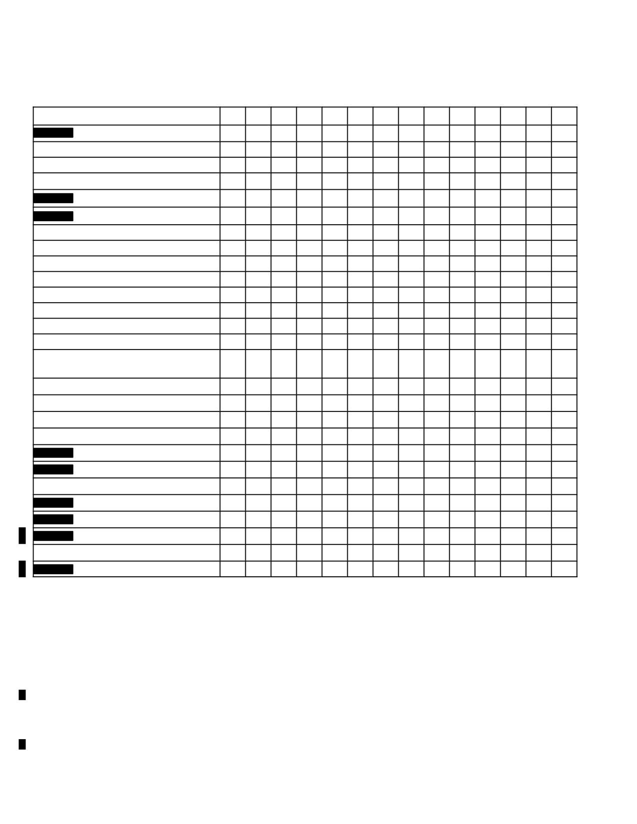
Table 2-12. DTC Upload Data - continued
Data to be Loaded*
A
B
C
D
E
F
G
H
I
J
K
L
M
N
BLK 2
COMM Presets
X
X
X2
X2
Suffixes
X
X
X
X
Expanders
X
X
X
X
SOI Authentication Codes
X
X
X
X
BLK 1
NAV Mode/Present Position
X
X
BLK 2
NAV Mode/Present Position
X
Boundaries and Phase Lines
X1
X
X
X
X
Engagement Areas
X1
X
X
X
X
Laser Codes
X1
X
X
X2
X2
ADF
X1
X
X
X2
X2
Weapons Selections
X
X
FCR Lethal Ranges
X
X
X
X
X
Sight Mode Selects
X
X
FCR Control Selects
X
X
Miscellaneous (Tail #, W & B,
Perf Data, ASE)
X
X2
X
X2
Emergency Procedures
X
X
X
X
X
Priority Fire Zones
X1
X
X
X2
X2
No Fire Zones
X1
X
X
X2
X2
Shot At
X2
X2
X2
BLK 2
Comm Member Directory
X
X
X
X
BLK 2
Comm Preset Directory
X
X
X
X
FCR Priority Scheme4
BLK 2
HF Configuration5
BLK 2
HF ECCM Configuration5
BLK 2
BMP Views3
Laser Keywords3
BLK 2
Threat Ranges3
* A = Master Load
B = All Comm Data C = All Mission 1
D = All Mission 2
E = Wpns/Sights
F = Emerg Proc
G = Thru Flt
H = Shot At
I = Misc
J = FCR Lethal Rng
K = Nav
L = DP Autoload
M = SP Autoload
N = WP Autoload
Note1 Master Load uploads Mission 1 data as current mission. To use Mission 2 data, it must be uploaded as
the current mission (overwrite Mission 1 Data).
Note2 Changes made during the current mission will be uploaded.
Note3 These files are automatically uploaded when the DTU door is closed and any DTU advisories are cleared.
Note4 FCR priority schemes are uploaded as necessary upon selection of the PRIORITY SCHEME button on the FCR
UTIL page.
Note5 HF files are only loaded when the HF button is selected.
Use or disclosure of this information is subject to the restriction(s) on the title page of this document.
2-122
Change 3
TM 1-1520-251-10
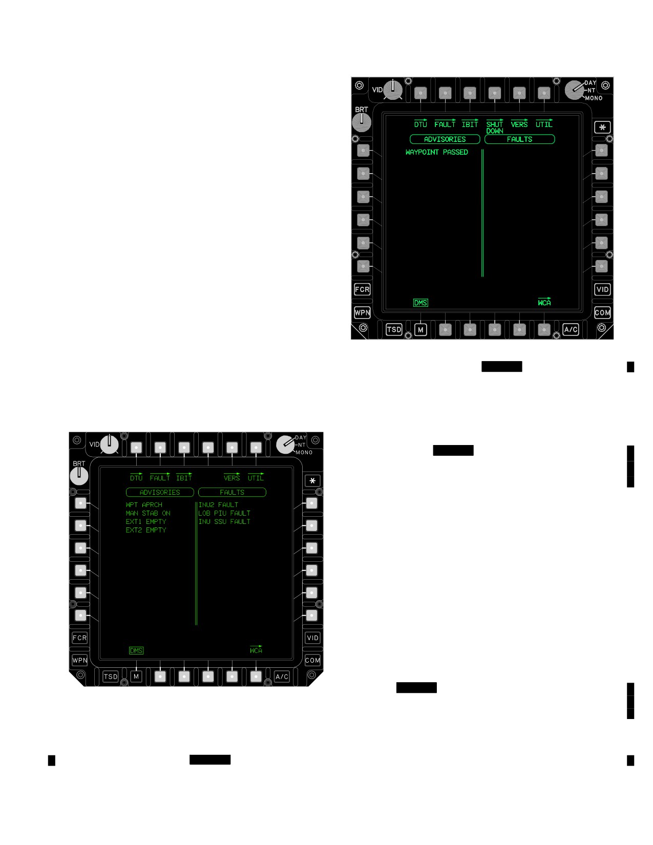
2.128 DMS PAGE
The DMS page (fig 2-109) is accessible from the MENU
page using the DMS button. For the purposes of the fol-
lowing discussions in this section, all subsequent pages of
the DMS subsystem are accessed from the DMS page.
The DMS page provides a listing of the system faults de-
tected through one of the BIT tests or direct input to the
system processor, and a complete listing of all current ad-
visory messages. When a fault is detected, the crew will
be given a message no greater than 18 characters long. If
more than one fault occurs with the same message, the
message is only displayed once. Faults and advisories
are listed in order of occurrence with the most recent in-
dication being given on the top of the list. If more than one
page of data is available for display, PAGE buttons shall
be displayed at the bottom bezel buttons and scroll both
columns of the display at the same time. The dividing lines
LBA5158
are drawn at all times on this format.
Figure 2-109A.
[
BLK 2
DMS Page]
The following selections are available on the DMS page:
• T1
DTU page button
• T2
FAULT page button
• T3
IBIT page button
• T4
BLK 2
SHUTDOWN page button
• T5
VERS page button
• T6
UTIL page button
• B2
PAGE down button
• B3
PAGE up button
• B6
WCA page button
2.128.1 DTU. The DTU button accesses the DTU page.
For description and operation of the DTU see paragraph
2.129.
2.128.2
FAULT. The FAULT button accesses the
FAULT page. For description and operation of the FAULT
page see paragraph 2.130.
2.128.3 IBIT. The IBIT button accesses the IBIT selec-
tion page. For description and operation of the IBIT page
see paragraph 2.131.
2.128.4 [
BLK 2
SHUTDOWN. The SHUTDOWN but-
LBA0428
ton accesses the SHUTDOWN page. For description and op-
eration of the SHUTDOWN page (para 2.131A).]
2.128.4 VERS. The VERS button accesses the software
version listing page of selected LRU software loads. For de-
Figure
2-109.
[
BLK 1
DMS Page]
scription and operation of the VERS page (para 2.132).
Use or disclosure of this information is subject to the restriction(s) on the title page of this document.
Change 2
2-123
TM 1-1520-251-10
2.128.5
UTIL. The DMS UTIL button provides the
means to access the DMS UTIL page. For the description
and operation of the DMS UTIL page (para 2.133).
2.128.6 PAGE. The DMS PAGE (UP/DOWN) list but-
tons are only displayed when the ADVISORIES column or
FAULTS column exceeds a count of 15. The PAGE (UP/
DOWN) buttons permit the operator to select the next
page of ADVISORIES/FAULTS where a maximum of 14
in either column could be displayed. When two pages are
presented, ADVISORIES and FAULTS are unique where
they are not repeated from one page to the other.
2.128.7 WCA. The WCA button accesses the WCA page.
For description and operation of the WCA page (para 2.134).
2.128.8 Advisory Column Listing Area. The left col-
umn of the DMS page lists current advisory information.
LBA5200
The most recent advisory messages are listed on the top
Figure 2-110.
[
BLK 1
DTU Page]
line as they occur, with previous messages shifting down
one line each time a new advisory is listed. The text string
includes up to 18 characters in length.
2.128.9 Fault Column Listing Area. The right column of
the DMS page lists the current faults. The text string includes
up to 18 characters in length. The most recent fault message
is listed on the top line as it occurs. Fault messages are an
abbreviated functional description of the messages displayed
on the FAULT page. Faults come from three sources: PBIT,
CBIT, and IBIT. PBIT is automatically performed when power
is applied to the system. CBIT is also automatic and is per-
formed at regular intervals on certain components. IBIT is dis-
cussed in paragraph 2.131.
2.129 DTU PAGE
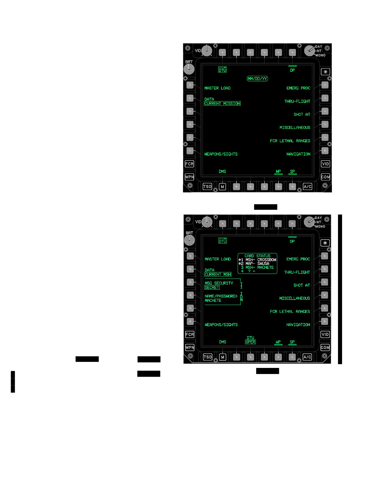
The DTU page ( [
BLK 1
fig
2-110], [
BLK 2
fig
2-110A] ) provides the capability to select the type of data
Figure 2-110A.
[
BLK 2
DTU Page]
to be loaded into the aircraft systems, and [
BLK 2
the
capabiltiy to enter the ownship’s TI USERNAME/PASS-
The following unique selections are available on the DTU
WORD and set the associated MSG SECURITY level.]
page:
Selecting a load function allows the system to accept se-
• T6
DP button
lected data from the DTC(s). The pilot has access to the
• L1
MASTER LOAD button
MASTER LOAD button that will load all primary system
• L2
DATA button
initialization data from the DTC at one time. The pilot also
has the ability to selectively load subsystem data from the
• L6
WEAPONS/SIGHTS button
DTC such as communications and navigation data files.
• R1
EMERG PROC button
Use or disclosure of this information is subject to the restriction(s) on the title page of this document.
2-124
Change 3
TM 1-1520-251-10
• R2
THRU-FLIGHT button
NOTE
• R3
SHOT AT button
No mission or map data is being transferred
to or from the DTC card(s) when the DTU
• R4
MISCELLANEOUS button
ACK button is displayed
• R5
FCR LETHAL RANGES button
c.
[
BLK 1
DTU Acknowledge. The DTU ACK (Ac-
• R6
NAVIGATION button
knowledge) momentary option button (B4) (fig 2-111) will be
• B3
[
BLK 2
DTU button]
displayed for advisories which can be acknowledged. Select-
• B5
WP button
ing ACK will clear the advisory and present the DTU page.
The DTU ACK button will not be displayed after selection.
• B6
SP button
Through this process the operator is acknowledging that the
2.129.1 DTU UPLOAD ADVISORIES & OPERATIONAL
data found on the DTC may or may not be valid for use.]
CONDITIONS.
d.
[
BLK 1
DTC Not On Board Advisory. When
the system processor detects that the DTC has not been
a.
[
BLK 2
Card Status Window. The card status
inserted into the DTR, a signal is sent to the DP to display
window ( fig 2-110A) is displayed in the top center of the DTU
the DTC NOT ON BOARD ADVISORY, colored WHITE.
page when the DTU mode is set to OPER. The card status
No selections will be available on the DTU page until a
window displays the type and name of the card in each of the
DTC is detected in the DTR.
four slots. If a card is not mission or map, type a “?” is dis-
played in place of the type. The DTC card status window is
e.
[
BLK 1
DTU Not Ready Advisory. When the
presented whether or not a mission card is installed. The air-
system processor detects that the DTC has not been up-
craft will use the first mission and map card it finds. The arrow
loaded into the DTR, a signal is sent to the DP to display
and white color indicate which cards are being used by the
the DTU NOT READY ADVISORY, colored WHITE. No
aircraft. ]
selection will be available on the DTU page until a DTC is
detected in the DTR.]
b.
[
BLK 1
Date Status Window. The DTU page
f.
[
BLK 1
DTC Corrupted Advisory. When the
date status window (fig 2-110) displays the date informa-
system processor detects (via counter) that the DTC car-
tion found in the DTC status block. The SP checks to en-
tridge status block upload has been attempted three times
sure that the information is within the valid ranges, but
without the operation proceeding to the MTOC upload se-
crewmembers must check to ensure that the DTC date is
quence, the SP will stop the operation and set the DTC
valid for any particular mission.]
CORRUPT ADVISORY message, colored WHITE. No
selections shall be available on the DTU page until the
DTC can be replaced or reprogrammed.]
g.
[
BLK 1
DTC Version Mismatch Adviso-
ry. When the DTC version expected by the system proc-
essor does not match the DTC version recorded on the
cartridge, the system processor sets the DTC Version
Mismatch ADVISORY message, colored WHITE. No
selections shall be available on the DTU page until the
DTC can be replaced or reprogrammed.]
h.
[
BLK 1
DTC Advisory Messages. The SP
checks three areas in the DTC status block data to deter-
mine DTC status: First, the SP will check for valid date,
then a valid status block checksum, and finally, a valid
Main Table Of Contents (MTOC). If any of these condi-
tions are invalid, a signal is sent to the DP. The DP pro-
cesses the signal and sends a signal to the MPD to dis-
play the appropriate advisory messages, colored WHITE
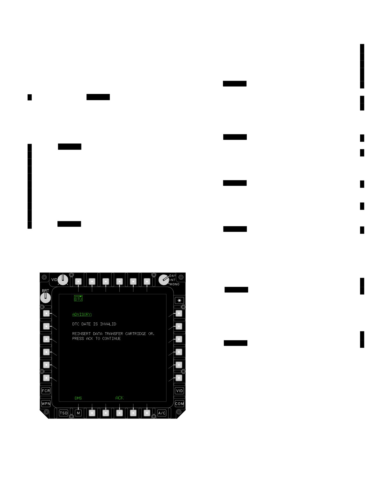
(fig 2-111). Any combination of the three messages can
appear at one time. These conditions do not keep the
crewmember from using the DTU functions; they are used
LBA2553
to inform him of DTC status before uploading operations
begin. Selecting the DTU ACK button will clear the screen
Figure
2-111. DTC Advisory Messages
and make available all the DTU page selections.]
Use or disclosure of this information is subject to the restriction(s) on the title page of this document.
Change 2
2-125
TM 1-1520-251-10
i.
[
BLK 2
DTU Connection Not Established Advi-
will be colored WHITE. If the load listing area contains
sory. When neither DP can establish a connection with the
more than 15 errors, the PAGE scrolling buttons will be
DTU over the fibre channel or when a DP has lost connection
displayed. The last line of text on page 1 will be the first
with the SP over the fibre channel, this advisory is displayed.
line of text on page 2. The number of pages available is
The DTU Connection Not Established advisory is colored
based on the number of errors listed.
white. No selections will be available until the DP establishes
a fibre channel connection with the SP and one of the DPs
has established a connection with the DTU.]
j.
[
BLK 2
Data Transfer Unit is Not Ready Adviso-
ry. When the DP detects that the DTU door is opened, it will
display this advisory. The Data Transfer Unit is Not Ready
advisory is displayed white. No selections will be available
until the DTU door is closed and a mission card is present.]
NOTE
DTC should not be removed until the last
line displays DTC WRITE COMPLETE.
k.
[
BLK 2
DTU Initialization Is in Progress Advi-
sory. This advisory is displayed when the DTU door is
first closed. While the advisory is displayed, the DTU is
checking which DTCs are present and what files are avail-
able on those DTCs.]
l.
[
BLK 2
DTU IBIT Is In Progress Adviso-
ry. This advisory is displayed when the DTU is currently
LBA5029
running IBIT. This advisory is colored white. No selections
will be available until the DTU has completed it’s IBIT.]
Figure
2-112. DTU Load Error Listing Area
m. IDM Data Transfer In Progress Adviso-
ry. When the crew elects to send data from either Mis-
• B4
ABORT Upload button
sion 1 or Mission 2 or to store data into Mission 1 or Mis-
sion 2, the data will be retrieved from or stored to the DTU.
o. PAGE. The DTU PAGE List buttons will be pre-
During this time, the IDM DATA TRANSFER IS IN PROG-
sented when the DTU load error listing area contains
RESS message, colored WHITE will be displayed on the
more than 15 errors to allow the operator to select the next
DTU page. No DTU selections will be available until this
page of the list The last line of text on the first page will be
task is completed.
the first line of text on the second page.
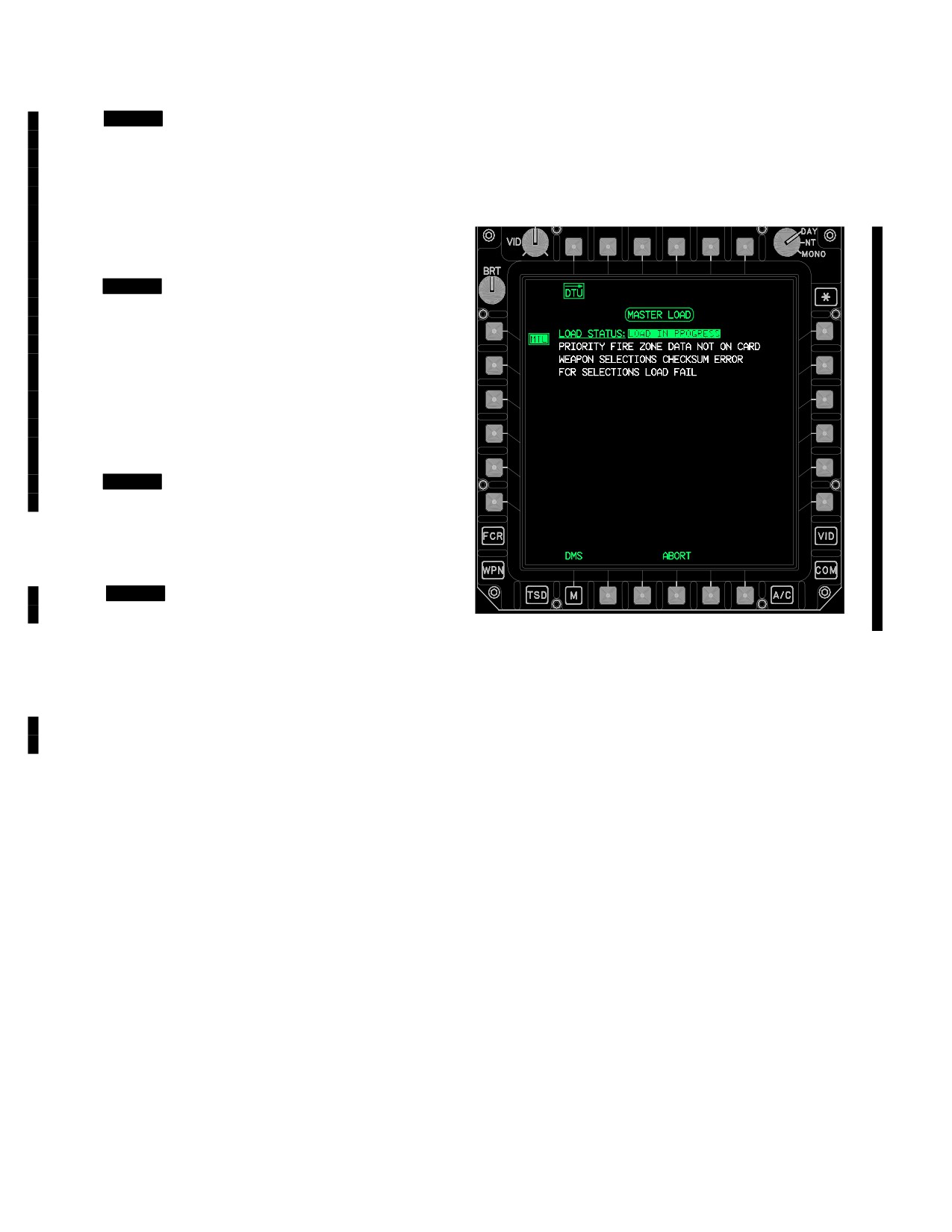
n. DTU Load Error Listing Area. The DTU load er-
p. ABORT. The ABORT Upload momentary option
ror listing area (fig 2-112) informs crewmembers of the
button will appear at the B4 position only when a DTU up-
upload being run, present status, and the loading errors
load is in progress. Selecting ABORT will interrupt the
detected during DTU data uploading. Error messages for
DTU up-load and display the current load status in the
these selections will then be listed accordingly. All errors
DTU load error listing area.
Use or disclosure of this information is subject to the restriction(s) on the title page of this document.
2-126
Change 2

TM 1-1520-251-10
2.129.2 DP. The DP auto load button ( [
BLK 1
fig
block from the DTC. The data is used by the ENG page for
2-110], [
BLK 2
fig 2-110A] ) provides feedback status dur-
displaying emergency procedures for warnings.
ing the automatic process of up-loading the DP. It will be dis-
played with a barrier on the DTU page when no upload is in
CAUTION
progress. [
BLK 1
The SP automatically initiates this
upload process to each DP that transitions from a non-opera-
Some thru - flight data will be lost unless
tional state to a normal or single DP operating mode.]
the THRU-FLIGHT button is selected
[
The SP initiates this upload process to both DPs
within one minute upon power up.
BLK 2
when one DP transitions from a nonoperational state to a
NOTE
normal or single operating mode.] This process is also initi-
[
BLK 2
The THRU - FLIGHT files cannot
ated as part of full system power-on and will take priority in
be updated if the DTU is in STBY.]
the up-loading operation. If an error is detected during
upload, the crewmember can also cause the automatic pro-
2.129.6 THRU-FLIGHT. The THRU-FLIGHT load button
cess to become initiated through the use of the THRU-
( [
BLK 1
fig 2-110], [
BLK 2
fig 2-110A] ) provides the
FLIGHT LOAD. [
BLK 1
DP autoload is in progress for
means of uploading thru-flight data. The purpose of THRU-
approximately 3 minutes.]
FLIGHT is to reduce the number of aircrew button selections
for initializing aircraft systems for continuing a mission.
THRU-FLIGHT occurs automatically in the air after an aircraft
NOTE
power interrupt, or as a selective option on the ground. The
Selection of MASTER LOAD or COMMU-
button will be displayed WHITE until the SP begins to over-
NICATIONS ALL will not load HF data.
write the THRU-FLIGHT data on the DTC. Data loaded from
THRU-FLIGHT is a mixture of AMPS data and data down-
2.129.3 MASTER LOAD. The MASTER LOAD button
loaded from the aircraft during flight. [
BLK 1
THRU-
( [
BLK 1
fig 2-110], [
BLK 2
fig 2-110A] ) provides crew-
FLIGHT is in progress for approximately 4 minutes.] The data
members with the means to upload all subsystem initializa-
is partitioned and loaded between the SP, DP and WP during
tion files at one time from the DTC. MASTER LOAD auto-
a THRU-FLIGHT autoload. Items marked as loading from the
matically selects mission 1 data as the default for uploading.
current mission (table 2-12) will be lost if not loaded immedi-
The purpose of the MASTER LOAD is to reduce the number
ately.
of aircrew button selections for initializing aircraft systems at
2.129.7 SHOT AT. The SHOT AT load button
the beginning of a mission. Data loaded from MASTER
( [
BLK 1
fig 2-110], [
BLK 2
fig 2-110A] ) provides the
LOAD is data loaded by the AMPS. [
BLK 1
MASTER
means of uploading the SHOT AT data blocks from the
LOAD is in progress for approximately 5 minutes.]
DTC. This is stored data of locations where Hellfire mis-
siles were launched to during an engagement.
2.129.3A MSG SECURITY. See SECURITY LEVEL
2.129.8 MISCELLANEOUS. The Miscellaneous Load
button defined (paragraph 3A.26.2)
button ( [
fig 2-110], [
fig 2-110A] ) pro-
BLK 1
BLK 2
vides the means of uploading checklist/emergency proce-
2.129.3B NAME/PASSWORD. The NAME/PASS-
dures data, weight and balance data, PLAN/MAX PERF
WORD button allows the operator to enter a user name
data, CHAFF settings and fuel corrector data (for CALC
and password to compare with what has previously been
fuel data) from the DTC. [
BLK 1
Miscellaneous Load
loaded into the IDM via the DTU. This information is re-
is in progress for approximately 1 minute.]
quired to login to the TI.
2.129.9 FCR LETHAL RANGES. The FCR LETHAL
RANGES load button ( [
BLK 1
fig 2-110], [
BLK 2
fig
2.129.4
WEAPONS/SIGHTS. The WEAPONS/
2-110A] ) provides the means of uploading the FCR lethal
SIGHTS button ( [
BLK 1
fig
2-110], [
BLK 2
fig
ranges data from the DTC. This data is used to assist the
2-110A] ) provides a means of uploading weapons/sights
FCR in prioritizing targets.
data from the DTC.
2.129.10 NAVIGATION. The NAVIGATION load button
2.129.5 EMERG PROC. The EMERG PROC load but-
( [
BLK 1
fig 2-110], [
BLK 2
fig 2-110A] ) provides the
ton ( [
BLK 1
fig 2-110], [
BLK 2
fig 2-110A]) provides
means of uploading the mode/present position from the DTC.
the means of uploading the emergency procedures data
This data is used to initialize the Inertial Navigation Unit (INU).
Use or disclosure of this information is subject to the restriction(s) on the title page of this document.
Change 4
2-127
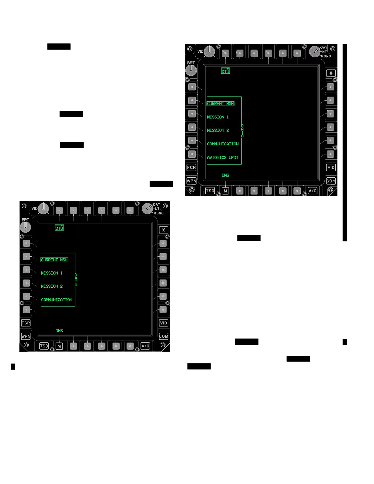
TM 1-1520-251-10
2.129.11 [
BLK 2
DTU MODE BUTTON. The The DTU
MODE two-state button (fig 2-110A ) is used to control the
state of the DTU. When the DTU is commanded to the stand-
by mode, all read operations will be cancelled and all write
operations will be finished. If power is removed from the DTU
in the operate state, any changes to files being written at that
point in time will be lost.]
2.129.12 WP. The WP auto load functions the same as
the DP auto load described in subparagraph 2.129.2 of
this section. [
BLK 1
WP autoload is in progress for
approximately 15 seconds.]
2.134.13 SP. The SP auto load functions the same as
the DP auto load described in subparagraph 2.129.2 of
this section. [
BLK 1
SP autoload is in progress for
approximately 10 - 15 seconds.]
2.129.14 DATA. The DATA multistate button (fig 2-113
and 2-113A) controls which upload options are presented.
DATA options include: CURRENT MISSION, MISSION 1,
MISSION 2 and COMMUNICATIONS and
BLK 2
AVIONICS UPDATE.
LBA5494
Figure 2-113A.
BLK 2
DTU Page DATA Selected
2.129.15
CURRENT MISSION DATA. When CUR-
RENT MISSION is the selected option of the DATA button
(fig 2-113), the following selections are available:
• L2
DATA CURRENT MSN button
• L3
DATA MISSION 1 button
• L4
DATA MISSION 2 button
• L5
DATA COMMUNICATION button
• L6
[
BLK 2
AVIONICS UPDATE button]
2.129.16 MISSION 1 DATA. When MISSION 1 is the
LBA5201
selected option of the DATA button ( [
BLK 1
fig 2-114],
Figure 2-113. DTU Page DATA Selected
[
BLK 2
fig 2-114A] ).
Use or disclosure of this information is subject to the restriction(s) on the title page of this document.
2-128
Change 4
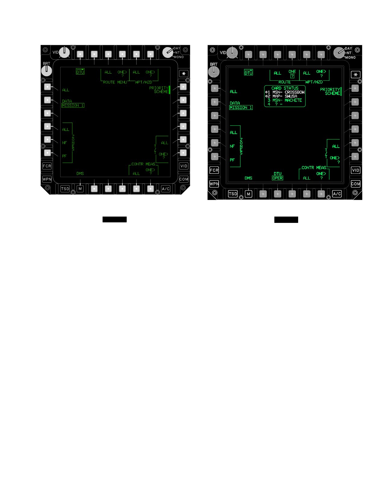
TM 1-1520-251-10
LBA3008
LBA5202
Figure 2-114.
[
BLK 1
MISSION 1 DATA
Figure 2-114A.
[
BLK 2
MISSION 1 DATA
Selections]
SELECTIONS]
Use or disclosure of this information is subject to the restriction(s) on the title page of this document.
Change 4
2-128.1/(2-128.2 blank)
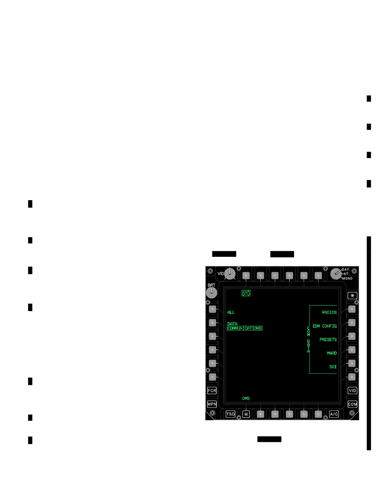
TM 1-1520-251-10
The following unique selections are available when MIS-
i. PRIORITY SCHEME. The PRIORITY SCHEME
SION 1 is selected:
load button provides feedback during the upload of a
• T3
ROUTE MENU ALL button
priority scheme. This process is initiated when a PRIOR-
ITY SCHEME selection of D through G is made on the
• T4
ROUTE MENU ONE button
FCR UTIL Page.
• T5
WPT/HZD ALL button
• T6
WPT/HZD ONE button
j. T/T ALL. The T/T ALL load button provides the op-
erator a means of uploading the targets and threats data.
• L1
ALL button
• L4
ZONES ALL button
k. T/T ONE. The T/T ONE load button provides the
• L5
ZONES NF button
operator a means of uploading one target or threat from
the targets and threats data (50 possible).
• L6
ZONES PF button
• R1
PRIORITY SCHEME button
l. CONTR MEAS ALL. The CONTR MEAS ALL
• R5
T/T ALL button
load button provides the operator a means of uploading
the control measures data.
• R6
T/T ONE button
• B5
CONTR MEAS ALL button
m. CONTR MEAS ONE. The CONTR MEAS ONE
• B6
CONTR MEAS ONE button
load button provides the operator a means of uploading
one control measure from the control measures data (49
a. ROUTE MENU ALL. The ROUTE MENU ALL
possible).
load button provides the operator a means of uploading
the route data. This data is used to set all ten mission 1
2.129.17 MISSION 2. When MISSION 2 is the selected
routes into the aircraft.
option of the DATA button the selections for the type of
mission data to be uploaded to the aircraft are the same
b. ROUTE MENU ONE. The ROUTE MENU ONE
as MISSION 1 data.
load button provides the operator a means of uploading
one route from the route data.
2.129.18 COMMUNICATIONS. When COMMUNICA-
TIONS is the selected option of the DATA button
c. WPT/HZD ALL. The WPT/HZD ALL load button
( [
BLK 1
fig 2-115], [
BLK 2
fig 2-115A] )
provides the operator a means of uploading the way-
points/hazards data. This data is used to set all waypoints
and hazards into the aircraft.
d. WPT/HZD ONE. The WPT/HZD ONE load button
provides the operator a means of uploading one waypoint
or hazard from the waypoints/hazards data. This data is
used to set one of the 50 possible MISSION 1 waypoints/
hazards into the aircraft.
e. ALL. The ALL load button provides the operator
a means of uploading all MISSION 1 data from the DTC.
This capability is used to rapidly set all configurations.
f. ZONES ALL. The ZONES ALL load button pro-
vides the operator a means of uploading both the priority
and no fire zones data. This data is used to set all zones
into the aircraft.
g. ZONES NF. The ZONES NF load button provides
the operator a means of uploading the priority no fire zones
data. This data is used to set all no fire zones into the aircraft.
LBA3007A
h. ZONES PF. The ZONES PF load button provides
the operator a means of uploading the priority fire zones data.
Figure
2-115.
[
BLK 1
COMMUNICATIONS DATA
This data is used to set all priority fire zones into the aircraft.
Selections]
Use or disclosure of this information is subject to the restriction(s) on the title page of this document.
Change 2
2-129
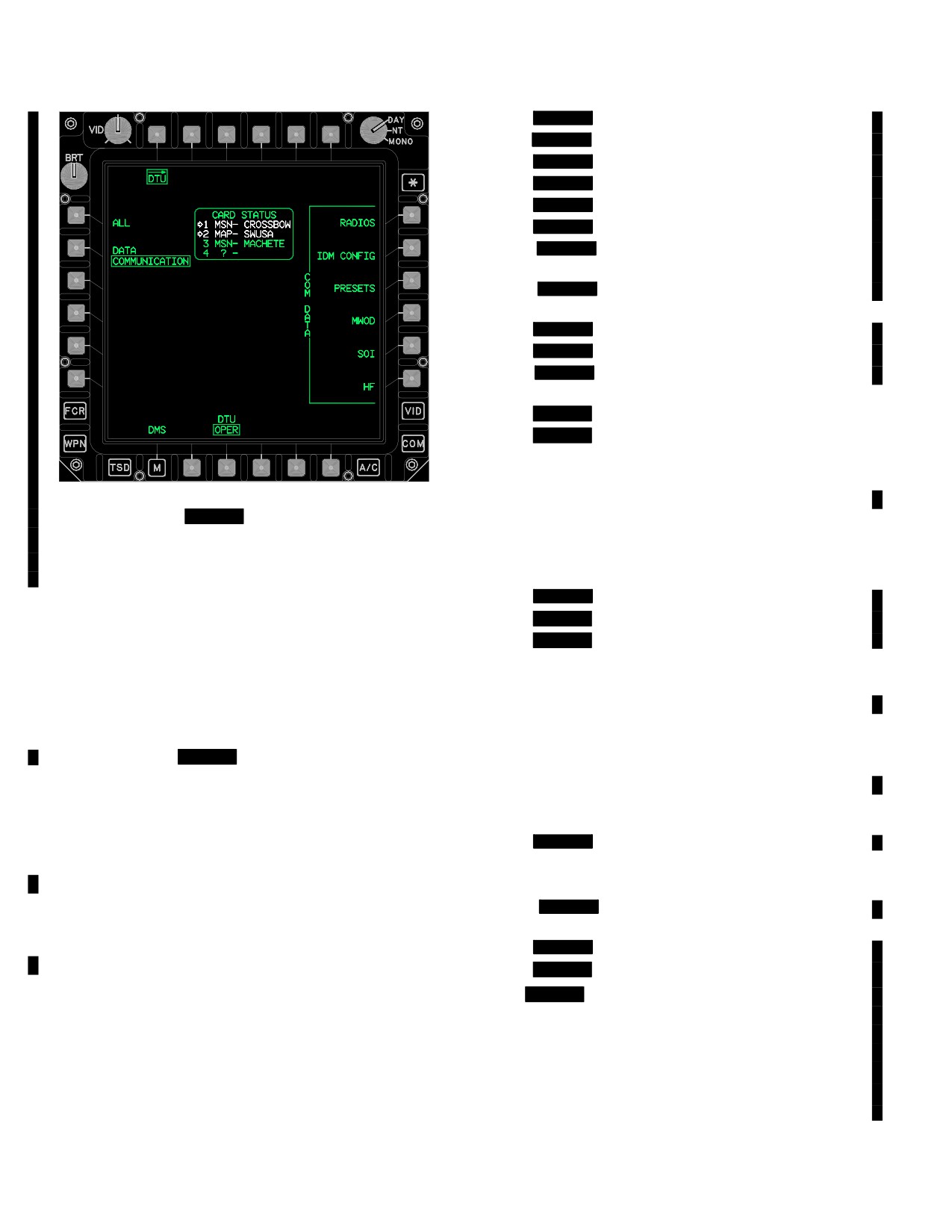
TM 1-1520-251-10
• [
BLK 1
IDM Auto Response Transmit Flag]
•
[
BLK 1
IDM Subscribers Net Assignments 1 - 5]
• [
BLK 1
IDM Protocol Address]
•
[
BLK 1
IDM Channels 1 - 4]
• [
BLK 1
IDM Nets 1 - 8 Configuration]
• [
BLK 1
IDM Channels 1 - 4 Net Assignments]
•
[
BLK 1
IDM Tacfire Authentication Transmit
Codes]
• [
BLK 1
IDM Tacfire Authentication Receive
Codes]
•
[
BLK 1
IDM Tacfire Freetext]
• [
BLK 1
IDM Tacfire Movement Messages]
• [
BLK 1
IDM Tacfire Auto Authentication Sub-
scriber]
•
[
BLK 2
IDM Config 1]
• [
BLK 2
IDM Config 2]
d. COM DATA PRESETS. The COM DATA PRE-
SETS load button provides the operator a means of
LBA5028
uploading the communications presets data from the
Figure 2-115A.
[
BLK 2
COMMUNICATIONS DATA
DTC. This data is used to rapidly set the communications
Selections]
presets configurations. The following data is loaded dur-
ing an ALL PRESETS upload:
The following unique selections are available when COM-
MUNICATIONS is selected:
• Comm Presets
• [
BLK 1
Comm Preset Nets]
• L1
ALL button
• [
BLK 2
Comm Member Directory]
• R1
COM DATA RADIOS button
• [
BLK 2
Comm Preset Directory]
• R2
COM DATA IDM CONFIG button
e. COM DATA MWOD. The COM DATA MWOD
• R3
COM DATA PRESETS button
load button provides the operator a means of uploading
• R4
COM DATA MWOD button
MWOD data from the DTC. This data is used to rapidly set
the MWOD configurations.
• R5
COM DATA SOI button
f. COM DATA SOI. The COM DATA SOI load but-
• R6
[
BLK 2
COM DATA HF button]
ton provides the operator a means of uploading the SOI
a. ALL. The ALL load button provides the operator a
data from the DTC. This data is used to rapidly set the SOI
means of uploading all COMMUNICATIONS data from the
configurations. The following data is loaded during an
DTC. This capability is used to rapidly set all configurations.
ALL SOI upload:
b. COM DATA RADIOS. The COM DATA RADIOS
• [
BLK 1
SOI Callsigns and Frequencies]
load button provides the operator a means of uploading
• SOI Suffixes
radio selections data from the DTC. This data is used to
• SOI Expanders
rapidly set the radios configurations.
• [
BLK 1
SOI Authentication Challenge and
c. COM DATA IDM CONFIG. The COM DATA IDM
Reply]
CONFIG load button provides the operator a means of
• [
BLK 1
SOI Tx Authentication Codes]
uploading the communications IDM DATA from the DTC.
• [
BLK 2
SOI Authentication Codes]
This data is used to rapidly set the IDM configuration data,
g.
[
BLK 2
COM DATA HF. The COM DATA HF
loaded via the IDM CONFIG load button, providing an inter-
load button provides the operator a means of uploading
face between aircraft radios and the mission equipment. Digi-
the HF data from the DTC. The data is used to rapidly con-
tal data is converted into or out of Frequency Shift key format
figure the HF radio. The following data is loaded during an
for transmission or reception as though it were voice. IDM
HF upload
communications occur over the crewmembers selected ra-
dio. The following data is loaded during an ALL IDM CON-
• HF Configuration
FIG upload:
• HF ECCM Configuration]
Use or disclosure of this information is subject to the restriction(s) on the title page of this document.
2-130
Change 2
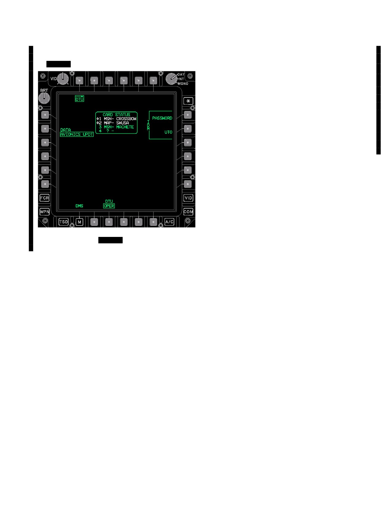
TM 1-1520-251-10
2.128.18A AVIONICS UPDT button. When AVIONICS
The following unique selections are available when
UPDT is the selected option of the DATA button
AVIONICS UPDT selected:
( [[
BLK 2
fig 2-115B] )
• R1
PASSWORD button
• R2
UTO button
a. PASSWORD. Selecting the PASSWORD button
will load the password/username files into the IDM. Pass-
word files contain an expiration tag of up to 60 days from
the day the files were created.
b. UTO. Selecting the UTO button will load up to five
UTO files into the IDM. UTO’s are current for an indefinite
period, they only change as units/equipment are removed
or added to a division.
LBA5495
Figure 2-115B.
[
BLK 2
AVIONICS UPDT DATA
Selections]
Use or disclosure of this information is subject to the restriction(s) on the title page of this document.
Change 4
2-130.1/(2-130.2 blank)
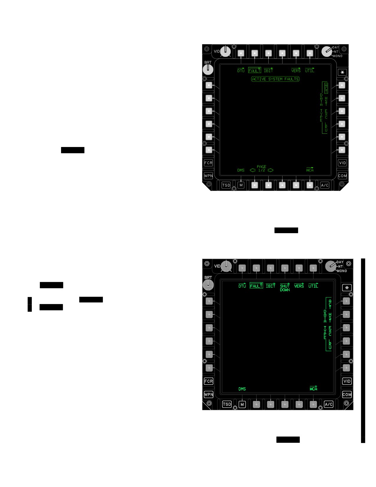
TM 1-1520-251-10
2.129.19 DTU Data For Autoloads. Data is downloaded
(stored) to the DTU from the aircraft and used to reload proc-
essors after a power interrupt or switchover.
The following files are downloaded to the cartridge, and
reloaded to the processors.
• Miscellaneous
• ADF Presets
• Laser Codes
• Shot At Data
• Priority Fire Zones
• No Fire Zones
• [
BLK 2
Comm Presets]
The following files are downloaded to the cartridge, but
are not reloaded.
• Waypoints and Hazards
• Control Measures
• Routes
LBA1807
• Targets and Threats
2.129.20 WP Requested Uploads. The laser keywords
are uploaded from the DTU on request by the WP. The laser
Figure
2-116.
[
BLK 1
Fault Page]
keyword upload occurs automatically and is not crew select-
able. Up to nine laser keywords can be stored on the DTC.
2.130 FAULT PAGE
The FAULT page button is available on the DMS,
[
BLK 2
SHUTDOWN], VERS, DMS UTIL, and WCA
pages. Selection of the FAULT page button displays the
FAULT page ( [
BLK 1
fig 2-116],
[
BLK 2
fig 2-116A] ), and displays all of the currently
active faults. Faults come from three sources; Power-up
Built-In-Test (PBIT), Continuous Built-In-Test (CBIT), and
Initiated Built-In-Test (IBIT). The PBIT function will be au-
tomatically performed when power is applied to the sys-
tem. Each component will run its PBIT when power is ap-
plied and report any line maintenance faults (e.g., LRU,
LRM) on the FAULT page. PBIT occurs without crew-
member input. The CBIT function will be performed at reg-
ular time intervals on certain components. When faults
are detected, they are reported in the same manner as the
PBIT faults. The IBIT faults reporting is discussed under
the IBIT page. The messages remain listed until the fault
is reset/fixed or until the system is powered down. When
15 or more faults are active, the format displays the PAGE
LBA5159
buttons as a means of accessing additional pages of data.
Faults are listed in order of occurrence with the most re-
cent fault given at the top of the list. The DATA TYPE but-
tons allow for selecting different type information.
Figure
2-116A.
[
BLK 2
Fault Page]
Use or disclosure of this information is subject to the restriction(s) on the title page of this document.
Change 2
2-131
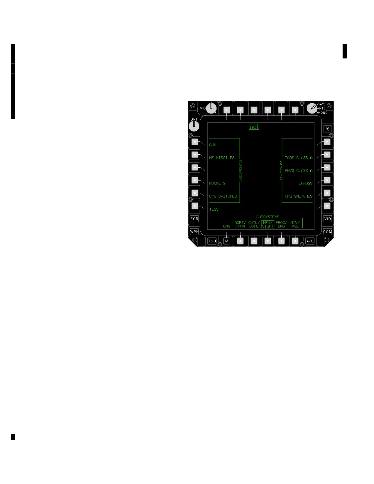
TM 1-1520-251-10
The following unique selections are available on the
when any IBIT is in progress. Exiting the IBIT page will not
FAULT page:
abort the IBIT. When the crewmember returns to the DMS
subsystem and selects the IBIT page button, the IBIT page
• R1
DATA TYPE ACT button
with the IBIT listing area (fig 2-118) is displayed if the test is
• R2
DATA TYPE HST button
still in progress or if it has been completed and the results are
not yet shown. The following selections are available on the
• R3
DATA TYPE EXC button
WEAPONS/SIGHTS/SUBSYSTEMS default IBIT page:
• R4
DATA TYPE LRU button
• B2
PAGE button
• B3
PAGE button
2.130.1 Fault Display Area. The fault display area pro-
vides a chronological listing of the last 30 active faults,
128 historical faults, or exceedences which have occurred
based on the data type selected. It is broken down into 15
lines of text, 35 characters in length with a maximum po-
tential of 10 pages.
2.130.2 DATA TYPE Active (ACT) Button. The DATA
TYPE ACT button provides the operator with the means of
accessing the currently active faults in the system. Upon
selection of the DATA TYPE ACT grouped option button,
the system shall display up to 30 currently active faults in
the fault display area.
2.130.3 DATA TYPE Historical (HST) Button. The
DATA TYPE HST button provides the operator with the
means of accessing all the faults that were detected and
LBA2539A
stored in the system. Upon selection of the DATA TYPE
HST grouped option button, the system displays up to 128
Figure 2-117. IBIT Page
historical faults in the fault display area.
The following selections are available on the IBIT page:
2.130.4 DATA TYPE Exceedences (EXC) Button. The
• L1
WEAPONS GUN button
DATA TYPE EXC button provides the operator with the
means of accessing all the exceedences that were detected
• L2
WEAPONS HF MISSILE button
and stored in the system. Upon selection of the DATA TYPE
• L4
WEAPONS ROCKETS button
EXC grouped option button, the system displays up to 128
• L5
WEAPONS PLT (or CPG) SWITCHES
exceedence records in the fault display area.
button
2.130.5 DATA TYPE Line Replaceable Unit (LRU) But-
• L6
TESS button
ton. The DATA TYPE LRU button provides the operator
• R1
SIGHTS FCR button
with the means of accessing the LRU faults that were de-
tected and stored in the system. Upon selection of the
• R2
SIGHTS TADS CLASS A (or B) button
DATA TYPE LRU grouped option button, the system dis-
• R3
SIGHTS PNVS CLASS A (or B) button
plays the LRU selections available.
• R4
SIGHTS IHADSS button
2.131 IBIT PAGE
• R5
SIGHTS PLT (or CPG) SWITCHES
button
IBIT allows crewmembers to test specific subsystems. The
• B2
SUBSYSTEMS ACFT/COMM button
IBIT page button displayed on the DMS page is the means of
access to the IBIT page (fig 2-117). The IBIT function is di-
• B3
SUBSYSTEMS CNTL/DSPL button
vided into subsystems for selection by the crewmembers.
• B4
SUBSYSTEMS WPN/SIGHT button
Upon entering the IBIT page from the DMS page, the system
• B5
SUBSYSTEMS PROC/DMS button
will default to the WEAPONS/SIGHTS/SUBSYSTEMS for-
mat. The crewmember is allowed to leave the IBIT page
• B6
SUBSYSTEMS NAV/ASE button
Use or disclosure of this information is subject to the restriction(s) on the title page of this document.
2-132
Change 2
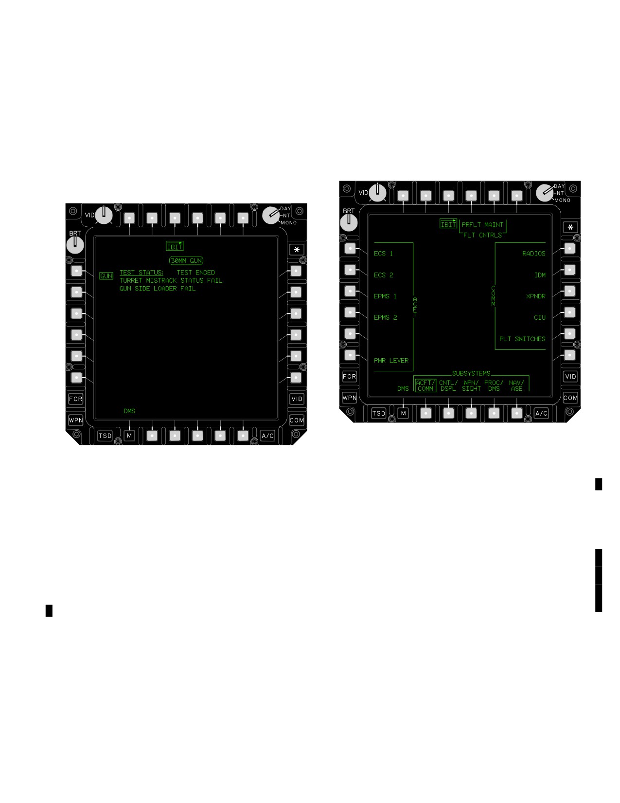
TM 1-1520-251-10
a. IBIT Listing Area. The IBIT listing area (fig 2-118) is
the steps listed. When the ACK is selected, either the next
used to inform the operator on the test being run, the status,
interactive page will be presented, or the IBIT listing area
and the faults detected during the IBIT. The TEST STATUS
will be presented with any faults displayed. This button is
line provides feedback to determine whether the test is com-
only used for IBIT that require operator interaction.
pleted, in-progress, or failed. This information is provided to
h. ACFT/COMM. The ACFT/COMM grouped option
the right of the test status title. The IBIT listing area will dis-
button provides the selections for IBIT test within the aircraft
play up to 15 lines of text with fault descriptions no greater
and communications subsystems.
than 35 characters in length. If more than 15 faults are dis-
played, the IBIT PAGE list buttons (B2 and B3) will be dis-
played to allow the operator to select the next page of the list.
LBA1960
LBA1885
Figure 2-119. ACFT/COMM Page - Pilot
Figure 2-118. IBIT Listing Area (Gun)
The following unique selections are available on the ACFT/
b. IBIT Page List (PAGE). The IBIT PAGE List but-
COMM format (fig 2-119):
tons (B2 and B3) (fig 2-118) are presented when the IBIT
listing area contains more than 15 faults. This allows the
• T4
FLT CNTRLS PRFLT button
operator to select the next page of the list. The last line of
• T5
FLT CNTRLS MAINT button
text on page 1 shall be the first line of text on page 2. Two
pages will be available for displaying any faults detected
• L1
ACFT ECS1 button
during IBIT test.
• L2
ACFT ECS2 button
c. IBIT Abort (ABORT). The IBIT ABORT momentary
• L3
ACFT EPMS1 button
option button (B4) is presented when an IBIT is in progress.
• L4
ACFT EPMS2 button
The ABORT button will interrupt the IBIT and display only the
IBIT listing area with no faults displayed. If the particular IBIT
• L6
ACFT PWR LEVER button
is an interactive test, or the test has a crew or advisory
• R1
COMM RADIOS button
prompt, the ABORT selection will also return the operator to
the IBIT listing area without any faults displayed.
• R2
COMM IDM button
d. IBIT Acknowledge (ACK). The IBIT ACK mo-
• R3
COMM XPNDR button
mentary option button (B5) is presented when an IBIT is in
• R4
COMM CIU button
progress and an interactive page is displayed. The ACK
button is used to acknowledge that the operator read and
• R5
COMM PLT (or CPG) SWITCHES
understood a warning or advisory message, or performed
button
Use or disclosure of this information is subject to the restriction(s) on the title page of this document.
Change 2
2-133
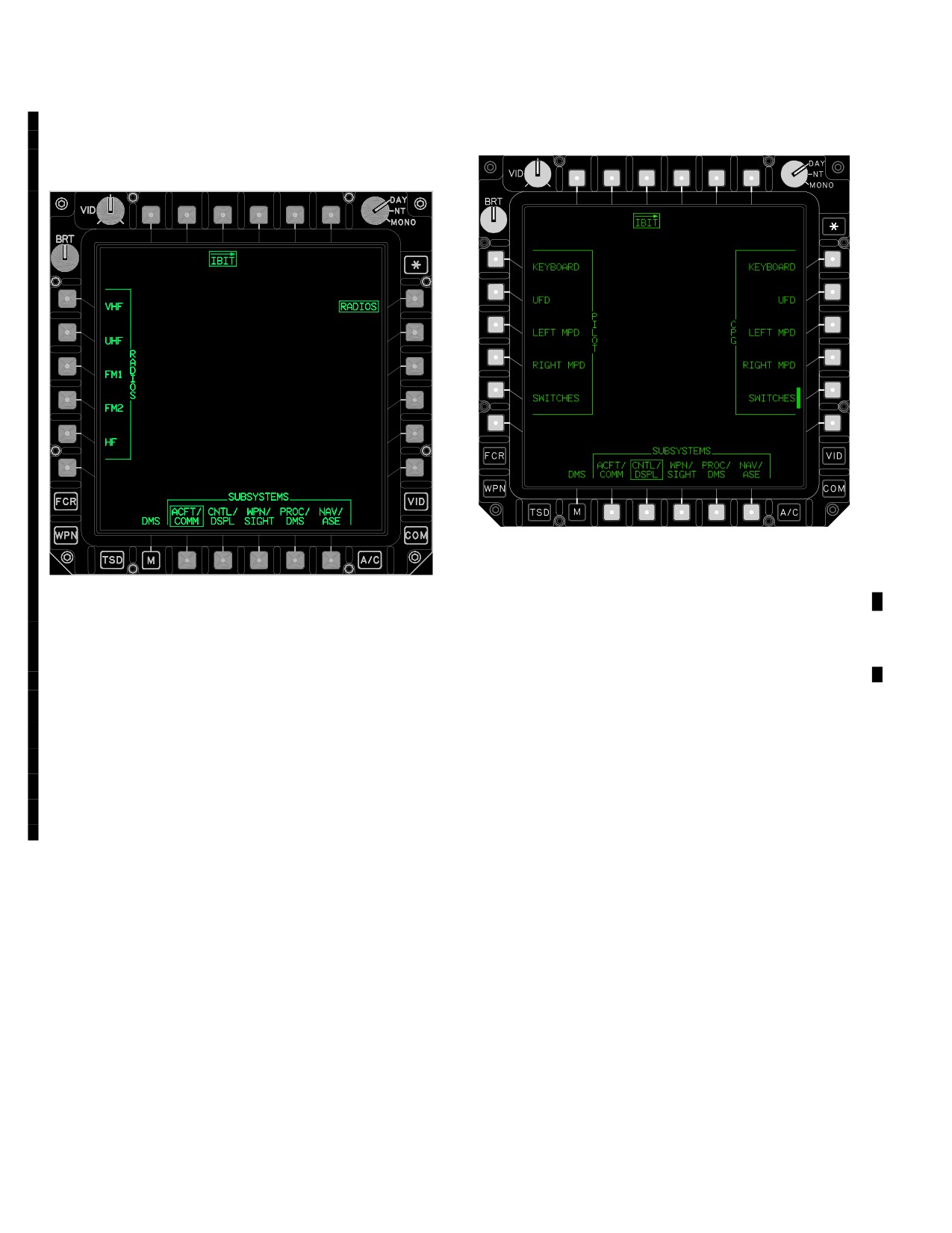
TM 1-1520-251-10
2.131.1 COMM RADIOS. The COMM RADIOS grouped
for the IBIT for the aircraft controls and displays subsys-
option button (fig 2-120) provides the selections for the indi-
tems.
vidual IBIT for the radios.
LBA1961
Figure 2-121. CNTL/DSPL Format
LBA5162
The following unique selections are available on the
CNTL/DSPL format (fig 2-121):
Figure 2-120. COMM RADIOS Page
• L1
PILOT KEYBOARD button
• L2
PILOT UFD/EUFD button
The following unique selections are available on the COMM
RADIOS format:
• L3
PILOT LEFT MPD button
• L4
PILOT RIGHT MPD button
• L1
RADIOS VHF button
• L5
PILOT SWITCHES button
• L2
RADIOS UHF button
• R1
CPG KEYBOARD button
• L3
RADIOS FM 1 button
• R2
CPG UFD button
• L4
RADIOS FM 2 button
• R3
CPG LEFT MPD button
• L5
RADIOS HF button
• R4
CPG RIGHT MPD button
2.131.2 CNTL/DSPL. The CNTL/DSPL (controls and
displays) grouped option button will provide the selections
• R5
CPG SWITCHES button
Use or disclosure of this information is subject to the restriction(s) on the title page of this document.
2-134
Change 2
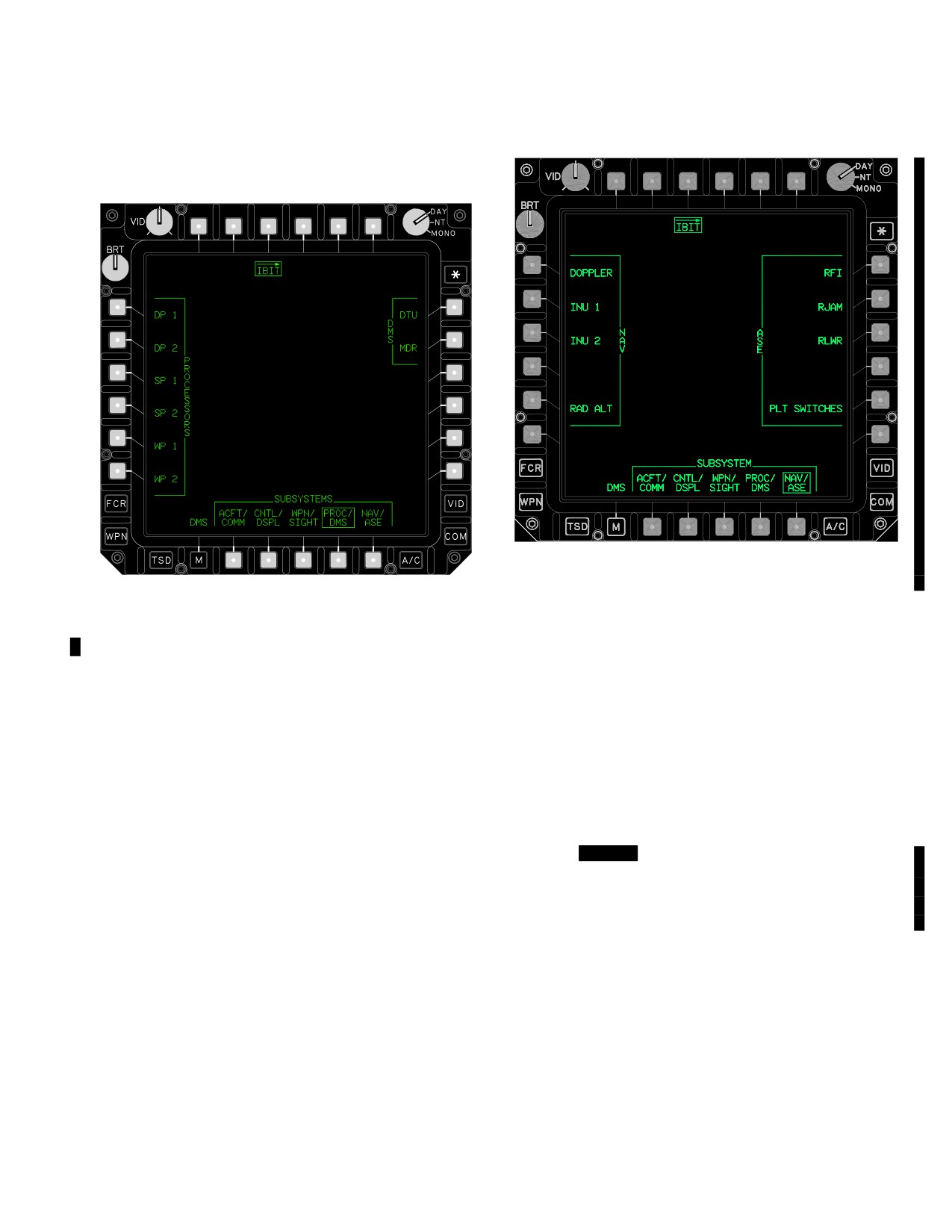
TM 1-1520-251-10
2.131.3 PROC/DMS. The PROC/DMS (processors and
provides the selections for the IBIT within the navigation and
DMS) grouped option button will provide the selections for
ASE subsystems.
the IBIT for the processors and Data Management Sub-
systems (fig 2-122).
LBA5160
LBA1554
Figure 2-123. NAV/ASE Format - Pilot Crew Station
The following selections are available from the NAV/ASE
Figure 2-122. PROC/DMS Format
format:
The following unique selections are available on the
• L1
NAV DOPPLER button
PROC/DMS format:
• L2
NAV INU 1 button
• L1
PROCESSORS DP1 button
• L3
NAV INU 2 button
• L2
PROCESSORS DP2 button
• L5
NAV RAD ALT button
• L3
PROCESSORS SP1 button
• R1
ASE RFI button
• L4
PROCESSORS SP2 button
• R2
ASE RJAM button
• L5
PROCESSORS WP1 button
• R3
ASE RLWR button
• L6
PROCESSORS WP2 button
• R5
ASE PLT (or CPG) SWITCHES button
• R1
DMS DTU button
2.131A [
BLK 2
SHUTDOWN PAGE]
• R2
DMS MDR button
The SHUTDOWN page (fig 2-124) is available on the DMS,
2.131.4 NAV/ASE. The NAV/ASE (navigation and aircraft
FAULT, VERS, and DMS UTIL pages. The SHUTDOWN
survivability equipment) grouped option button (fig 2-123)
page is used to access aircraft subsystem shutdown controls.
Use or disclosure of this information is subject to the restriction(s) on the title page of this document.
Change 2
2-135
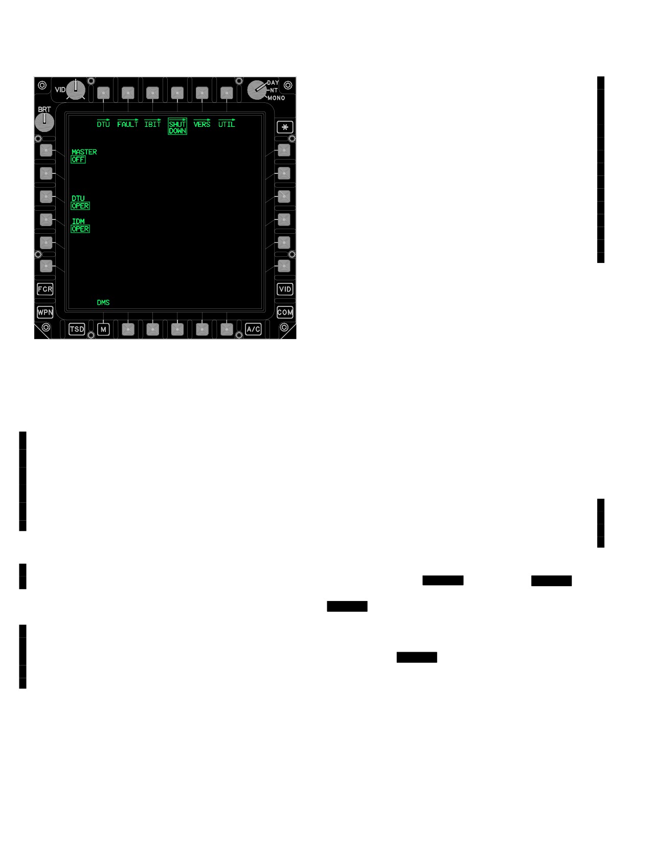
TM 1-1520-251-10
2.131A.4 PNVS button. The PNVS button enables and
disables the PNVS.
2.131A.5 MODE 4 HOLD button. Selecting the MODE
4 HOLD button prevents erasure of the Mode 4 Codes in
the Kit-1C computer when the aircraft is on the ground
and power is removed from the XPNDR system. The
codes will be lost if power is removed for more than 20
seconds. The button will be displayed with a barrier when
the aircraft is in the air. Following a selection, if the aircraft
transitions to an ’in - air’ state for more than 60 seconds,
the hold selection will be reset. Once on the ground, it will
be necessary to again select the MODE 4 HOLD button to
retain the codes. The MODE 4 HOLD button is not dis-
played if the Kit-1C computer is not installed
2.131A.6 IDM button. The IDM button permits the opera-
tor to toggle between standby and operate. The IDM is initial-
ized to STBY when the aircraft is powered up. When a COM
upload is commanded which contains IDM configuration data
(such as MASTER LOAD, IDM CONFIG, COM ALL, etc.),
the IDM will automatically mode to OPER. When the IDM is
LBA5161
in STBY, digital messages cannot be transmitted or received.
The IDM must be set to STBY before removing power from
Figure 2-124. SHUTDOWN PAGE
the IDM. When in STBY, an IDM IN STANDBY advisory will
The following unique selections are available on the
be displayed on the COM page and UFD/EUFD. Failure to
SHUTDOWN page:
set the IDM to STBY could corrupt the IDM’S software.
• L1
MASTER OFF button.
2.131A.7 DTU button.
The DTU button is used to place
the DTU in the standby mode prior to aircraft shutdown.
• L2
FCR button.
The DTU button toggles between STBY and OPER. The
• L3
TADS button.
DTU is set to OPER at aircraft start up. The DTU must be
• L4
PNVS button.
set to STBY prior to removing power from the DTU. Fail-
ure to set the DTU to STBY could corrupt the DTC.
• R5
MODE 4 HOLD button
2.131A.8 Stabilator. The stabilator position is provided
• R6
IDM button.
to the aircrew by the stabilator symbol and functions as
• B3
DTU button.
described on page 2 - 102. It is displayed on the SHUT-
2.131A.1 MASTER OFF button. The MASTER OFF but-
DOWN page for access during shutdown.
ton is used to shutdown aircraft systems. Selecting the MAS-
2.132 VERSION (VERS) PAGE
TER OFF button will set the FCR, TADS, and PNVS to off. In
addition, it will set the DTU and IDM to STBY. The MODE 4
The VERS page ([
BLK 1
fig
2-125], [
BLK 2
fig
HOLD button and Stabilator symbol are not affected by this
2-125A]) is available on the DMS page, FAULT page,
selection.
[
BLK 2
SHUTDOWN page], DMS UTIL page, and WCA
page. The VERS page button will be the means of accessing
2.131A.2 FCR button. The FCR button enables dis-
to the software VERS page. The VERS page provides a list-
ables the FCR.
ing of all the software versions currently used by the systems
to the operator. [
BLK 2
The VERS page is organized into
2.131A.3 TADS button. The TADS button enables and
subsystems similar to the IBIT page. the default page is the
disables the TADS.
PROC/DMS page.]
Use or disclosure of this information is subject to the restriction(s) on the title page of this document.
2-136
Change 4
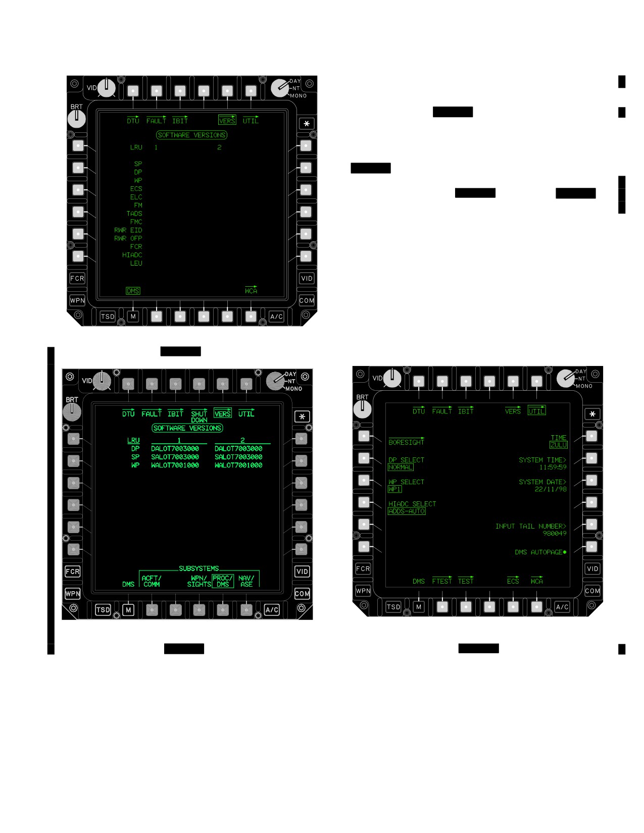
TM 1-1520-251-10
The following unique selection is available on the VERS
page:
• B2 - B6 [
BLK 2
SUBSYSTEMS buttons]
2.133 DMS UTILITY (UTIL) PAGE
The DMS UTIL button is displayed on the DMS, FAULT,
[
BLK 2
SHUTDOWN], VERS and WCA pages. The DMS
UTIL page provides the means of accessing the various
DMS utility functions ( [
BLK 1
fig 2-126], [
BLK 2
fig
2-126A] ). On the left, the DMS UTIL page provides all the
BORESIGHT page functions along with some maintenance
operational functions. Maintenance operators are provided
with a means of DP, WP and Highly Integrated Air Data Com-
puter (HIADC) soft switch selection capability for fault isola-
tion purposes. These are noted by the DP SELECT, WP SE-
LECT, and HIADC SELECT functions. On the right, the DMS
UTIL page provides the current local or Zulu time, system
time, current date, aircraft tail number and CPG autopage
disable function of the aircraft systems Engine page. The
LBA1880
FTEST page, TEST page, and ECS functions are accessible
at the bottom of the DMS UTIL page.
Figure 2-125.
[
BLK 1
Version (VERS) Page]
LBA1963A
LBA5064
Figure 2-125A.
[
BLK 2
Version (VERS) Page]
Figure 2-126.
[
BLK 1
DMS UTIL Page]
Use or disclosure of this information is subject to the restriction(s) on the title page of this document.
Change 2
2-137
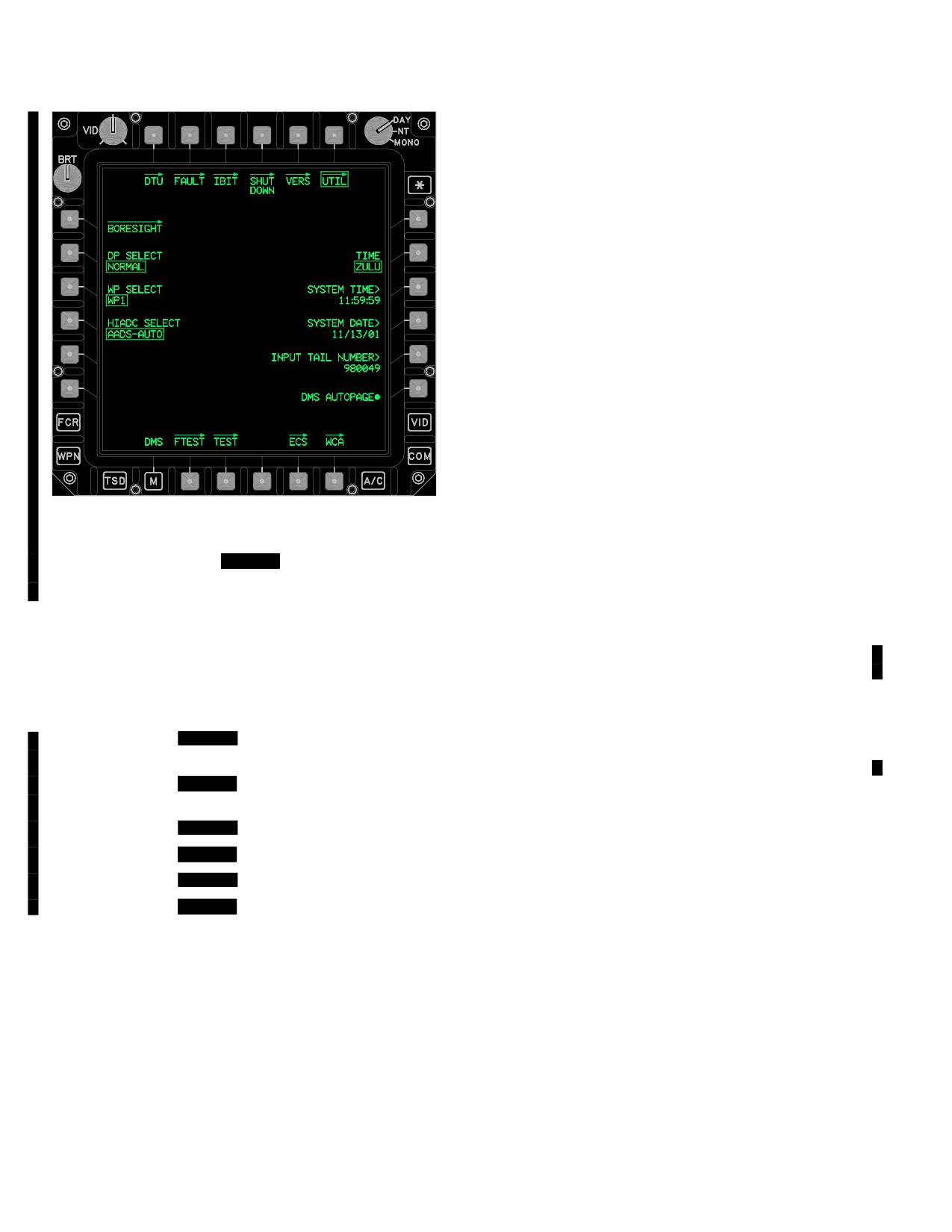
TM 1-1520-251-10
2.133.1 BORESIGHT. The BORESIGHT Page (L1) pro-
vides the means for conducting CBHK procedures and bore-
sighting the TADS, PNVS, Pylons, Gun, INU1, INU2, Dop-
pler, Highly Integrated Air Data Computer (HIADC), Gun
Dynamic Harmonization, and Blade Positioning Synchroniza-
tion (BPS) with the Fire Control Radar, and the Tactical En-
gagement Simulation System (TESS) as part of the TADS
and Gun boresight options.
2.133.2 DP SELECT. The DP SELECT multi-state button
provides the means for the maintenance operator to select
between DP Normal, DP1 Single or DP2 Single Operation.
These selections are for ground maintenance fault isolation
purposes only, and are not selectable when the aircraft is in
the air.
2.133.3 WP SELECT. The WP SELECT multi-state button
provides the means for the maintenance operator to select
between WP1 Single or WP2 Single Operation. These selec-
tions are for ground maintenance fault isolation purposes
only, and are not selectable when the aircraft is in the air.
2.133.4 HIADC SELECT. The HIADC SELECT multi-
state button provides the means for the maintenance op-
LBA5203
erator to select the Airspeed And Direction Sensor
(AADS) between AADS-AUTO, AADS-LH, or AADS-RH
Operation. These selections are for ground maintenance
Figure 2-126A.
[
BLK 2
DMS UTIL Page]
fault isolation purposes only, and are not selectable when
The following unique selections are available on the DMS
the aircraft is in the air or the power levers are not OFF.
UTIL page:
2.133.5 TIME. The DMS TIME two-state button sets the
• L1
BORESIGHT page button
display mode of time to LOCAL or ZULU. An L or Z ap-
pears on the UFD/EUFD to designate either local or Zulu
• L2
DP SELECT button
time.
• L3
WP SELECT button
2.133.6 SYSTEM TIME. The DMS SYSTEM TIME but-
• L4
HIADC SELECT button
ton allows the operator to input current local or Zulu time,
depending on the DMS TIME two-state button setting.
• R1
[
BLK 1
TIME (LOCAL/ZULU)
The DMS system time will also be found in the lower right-
button]
hand corner of the UFD/EUFD.
• R2
[
BLK 2
TIME (LOCAL/ZULU)
2.133.7 SYSTEM DATE. The DMS SYSTEM DATE
button]
button allows the operator to input the current date. The
• R2
[
BLK 1
SYSTEM TIME button]
current date can be input through the keyboard unit (KU).
The KU is enabled when the operator selects the DMS
• R3
[
BLK 2
SYSTEM TIME button]
SYSTEM DATE button.
• R3
[
BLK 1
SYSTEM DATE button]
2.133.8 INPUT TAIL NUMBER. The DMS INPUT TAIL
• R4
[
BLK 2
SYSTEM DATE button]
NUMBER button allows the operator to input the aircraft
tail number into the SP. The KU is enabled when the DMS
• R5
INPUT TAIL NUMBER button
INPUT TAIL NUMBER button is selected. The 6 digit
• R6
DMS AUTOPAGE On/Off button (CPG
number is displayed in the bottom mode portion of the but-
only)
ton position after the user completes the input.
• B2
FTEST page button
2.133.9 DMS AUTOPAGE. The DMS AUTOPAGE on/off
button allows the CPG to disable automatic paging of warn-
• B3
TEST page button
ing indications on the ENG page in the CPG crew station.
• B5
ECS page button
The default state for DMS AUTO on/off button will be on.
Use or disclosure of this information is subject to the restriction(s) on the title page of this document.
2-138
Change 2
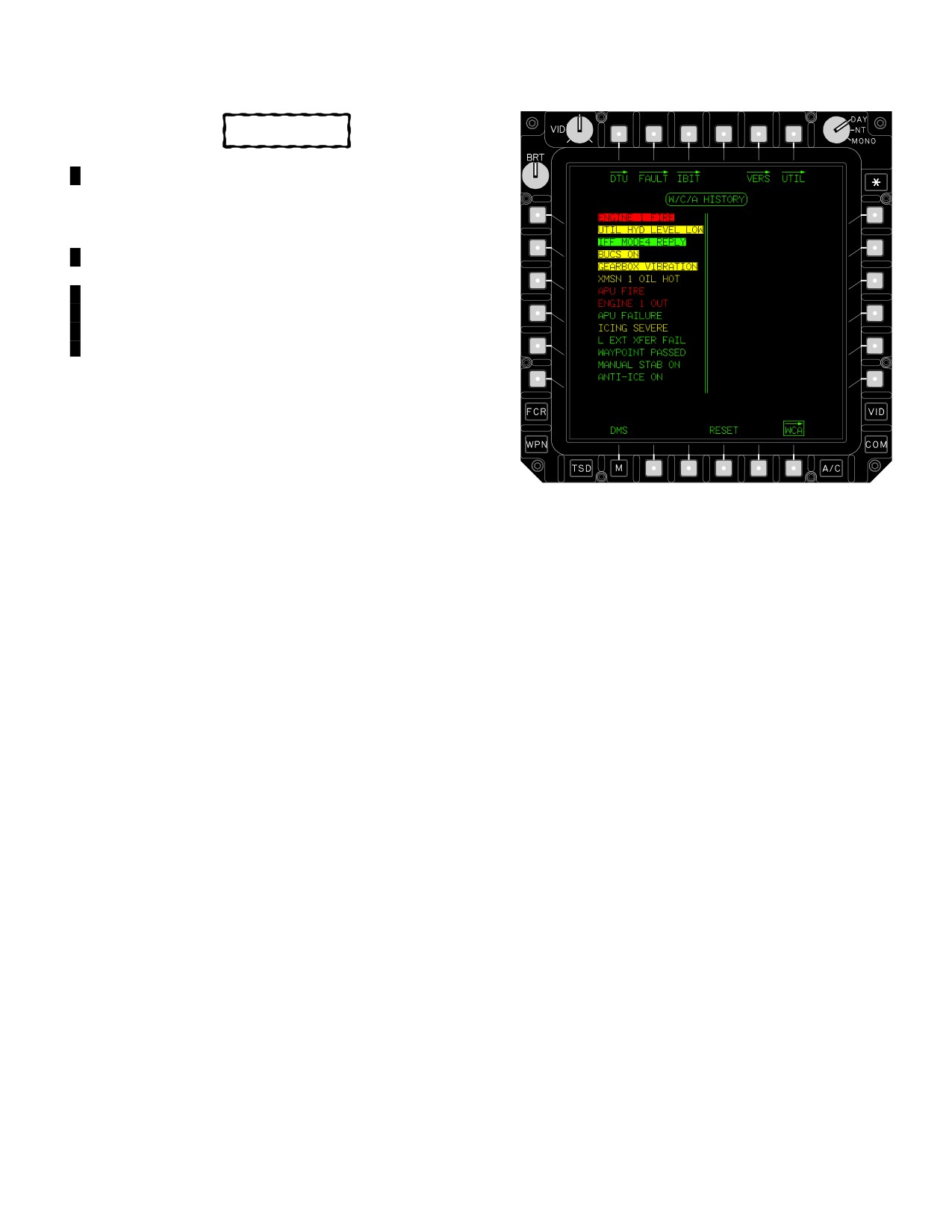
TM 1-1520-251-10
CAUTION
The FTEST/ETEST page button is designed
for engineering use only. System damage
may occur if used by unauthorized person-
nel.
2.133.10 FTEST/ETEST. The FTEST page button allows
the engineering maintenance operator to perform test func-
tions on the Fire Control Radar (FCR). The ETEST (engi-
neering test) page provides access to three test formats whi-
ch allows the engineering maintenance operator to perform
test functions.
2.133.11 TEST. The TEST page button allows the
maintenance operator to access the read memory loca-
tion (address) functions for the DP, SP, WP and Hellfire
Missiles. When any of these test modes are tested, a
memory location listing area is provided where hexadeci-
mal information is provided for the test being run.
LBA1964
2.133.12 ECS. The ECS page provides a means of dis-
playing the current Environmental Control System variables
Figure 2-127. WCA Page
affecting each crewstation, ECS components and EFABs.
The following selections are available on the WCA page:
• B2
PAGE button
2.134 WARNING/CAUTION/ADVISORY (WCA)
• B3
PAGE button
PAGE
• B4
RESET button
2.134.1 PAGE. The WCA PAGE List buttons (B2 & B3) al-
The WCA button is available on the DMS, FAULT, VERS,
low the operator to select the next page when the WCA
ENG, and DMS UTIL page. The WCA page button is the
LISTING AREA contains 30 or more W/C/As. The last mes-
means of accessing the WCA page. The WCA page (fig
sage on page 1 shall be the first message on page 2. This
2-127) provides the operators with the total listings of cur-
same approach will occur for additional pages if applicable.
rent and past Warnings, Cautions, and Advisories. The
WCA page W/C/A HISTORY area is capable of listing up
2.134.2 RESET. The WCA RESET momentary button is
to 128 W/C/A messages which can be up to 18 characters
used to acknowledge that the operator has seen the W/C/A
long, in 2 columns, on 5 pages. W/C/As are listed in order
messages that have occurred since the last time the WCA
of occurrence with the most recent occurrence given at
RESET momentary option button was selected. These mes-
the top of the left column on page 1, wrapping around to
sages will then remain listed in inverse video until the opera-
the top of the right column, and then to page 2 left column.
tor selects WCA RESET or when the system is powered
New W/C/A messages are displayed in inverse video to
down. Upon selecting the WCA RESET momentary button,
distinguish them from those W/C/A messages which oc-
the inverse video of the new W/C/A messages is removed.
curred since the last time the operator selected the WCA
Once a WCA has been acknowledged, if the condition rec-
RESET function.
curs, the message will not be displayed as inverse video.
Use or disclosure of this information is subject to the restriction(s) on the title page of this document.
Change 4
2-139

TM 1-1520-251-10
2.135 WCA OPERATIONS
NOTE
MSTR
WARN
The crewstation lighting is partially compat-
ible with the AN/AVS - 6 goggles. Illumina-
tion of the Master Caution Light may de-
MSTR
grade NVG operations.
CAUT
The warning/caution/advisory (WCA) system provides the
crewmembers with the status of all warnings, cautions, and
PILOT STATOPM
advisories via a master warning lighted pushbutton, a master
caution lighted pushbutton, the fire detect and extinguish pan-
el, UFD/EUFD messages, MPD messages, voice messages
MSTR
MSTR
for warnings, and audio tones for cautions and advisories.
WARN
CAUT
The WCA system definition relates to aircraft systems and
not threat/survivability information. The basis for this distinc-
tion is the difference in the desired response between a WCA
CPG STATION
LBA0482
message and a threat warning. The WCA messages indicate
the need to take note of system malfunctions and take cor-
rective action if possible, while threat warnings do not indicate
Figure 2-128. Master Warning/Master Caution
this same need. Mission equipment related messages may
Lighted Buttons
be displayed on the optical relay tube (ORT) and IHADSS as
b. UFD/EUFD. Warnings are displayed in the top
required. The following paragraphs define and describe WCA
left area of the UFD/EUFD (fig 2-129 and 2-130). The
system operations.
UFD/EUFD is capable of displaying up to a maximum of
2.135.1 Warning Operations. A warning indicates the ex-
[
BLK 1
five] [BLK 2
seven] warning messages simul-
istence of a hazardous condition requiring immediate correc-
taneously with up to 18 characters per message. Any pre-
tive action. Warning conditions are indicated by the MSTR
vious warning messages that have not been corrected will
WARN lighted pushbutton, the UFD/EUFD message in the
move down one line to allow the current message to be
warning display area, voice messages, and MPD format dis-
displayed on the top line. When a condition is corrected,
plays. For the engine and auxiliary power unit (APU) fire
the warning message will be removed from the UFD/
conditions, the fire detect/extinguish panel provides operator
EUFD. The format of a UFD/EUFD warning message is
indications. Section XVII, Table 2-13 lists all warning mes-
general heading first, specific location or subsystem next,
sages and associated descriptions. The associated emer-
then the nature of the emergency. As an example, in the
gency procedures for these warnings are established in
Engine 1 Out warning message (fig. 2-129), the general
Chapter 9.
heading is ENG, the specific location is 1, and the nature
a. MSTR WARN Lighted Button. The MSTR
of the emergency is OUT.
WARN lighted button (fig 2-128) alerts crewmembers to
observe a warning message displayed on the UFD/EUFD
and announced by the voice message system. The MSTR
ENG 1 OUT
WARN lighted button will flash “MSTR WARN” in NVIS
yellow at a 4Hz rate when a warning is detected. When
one crewmember depresses the flashing MSTR WARN
button, the voice message will be extinguished in both
crew stations. However, each crewmember is required to
depress the MSTR WARN lighted button in their respec-
LBA1815
tive crew station to acknowledge the warning condition,
and turn off the indicator light.
Figure 2-129. Up Front Display (UFD)
Use or disclosure of this information is subject to the restriction(s) on the title page of this document.
2-140
Change 2

TM 1-1520-251-10
length for cautions is limited to 18 characters. When a caution
condition is detected, the new caution message will be dis-
(Warnings)
(Cautions)
(Advisories)
played on the top line of the caution display section of the
UFD/EUFD. If more than [
BLK 1
five] [
BLK 2
seven]
caution messages have been detected, a DOWN arrow will
be displayed to the left of the last message displayed. The
operator may then use the VIEW rocker switch at the upper
LBA5204
left corner of the UFD/EUFD to scroll the display to additional
messages. Messages on the top line will shift off the display
Figure 2-130. Enhanced Up Front Display (EUFD)
and the next [
BLK 1
five] [
BLK 2
seven] messages will
c. Voice Messages. Warning annunciations are ac-
be displayed in the viewing area. The list will continue to
companied by a voice message given through the aircrew
move in this manner if the VIEW switch is held down continu-
headset. Verbiage of the voice messages are listed in Table
ously for more than 2 seconds. When the end of the list is
2-13. A message is repeated until it is no longer active or the
reached, the list will stop moving. If the operator presses the
operator acknowledges the message by depressing the
VIEW switch twice quickly, the top of the list will be displayed.
MSTR WARN lighted button. At that time, if the voice mes-
c. MPD. Cautions and warnings are listed in the
sage has been given at least once, it will be silenced. If the
lower portion of the ENG page in a time sequenced list.
voice message has not been given once, it will be completed
Cautions (like warnings) will remain on the MPD list until
before the voice is stopped. Warning messages are given in
the situation is corrected.
the time of occurrence order. If more than one warning oc-
d. Caution Tones. A caution tone consisting of a
curs, they will alternate. A single acknowledgement of the
concurrent low then high frequency tone will sound for 1.5
MSTR WARN lighted button will extinguish multiple voice
seconds upon detection of a caution. The tone will repeat
messages, provided that each has been output through the
every 10 seconds until the operator acknowledges the
headset once.
caution or the situation is corrected. When the operator
d. MPD. For warnings, the current MPD display will au-
acknowledges the caution by depressing the illuminated
tomatically change to the ENG In-Flight page with the in-
MSTR CAUT button, the tone will stop.
formation needed by the operator to quickly assess the situa-
2.135.3 Advisory Operations. An advisory indicates
tion and take corrective action. For warnings, emergency
safe or normal configuration, condition, or performance,
procedures are given on the ENG In-Flight page if they have
operation of essential equipment, or attracts attention and
been loaded from the DTC, except for HIGH RTR and ENG
imparts information for routine action. Advisory conditions
CHOP.
are indicated by a message in the UFD/EUFD advisory
2.135.2 Caution Operations. A caution indicates the exis-
display area. Some advisory tones also play an
tence of an impending dangerous condition requiring atten-
associated tone or voice message. Table 2-15 lists all ad-
tion but not necessarily immediate action. Caution conditions
visory messages and associated descriptions. Chapter 9
are indicated by the MSTR CAUT lighted button, the UFD/
lists advisories and associated corrective actions if re-
EUFD caution display area, and a caution tone. Caution in-
quired.
dications for mission equipment may also be given on the
a. UFD/EUFD. Advisory message length is limited to
ORT or IHADSS. Caution conditions are indicated by the
18 characters. When an advisory occurs, it will be added to
MSTR CAUT lighted button (fig 2-128), the UFD/EUFD cau-
the advisory listing on the UFD/EUFD. If more than [
tion display area, and a caution tone. Chapter 9 lists all cau-
BLK 1
five] [
BLK 2
seven] advisory messages have
tions and associated corrective actions. Table 2-14 lists all
been detected, a DOWN arrow will be displayed to the left of
caution messages and associated descriptions.
the last message displayed. The crewmember may then use
a. MSTR CAUT Lighted Button. The MSTR CAUT
the VIEW rocker switch at the upper left corner of the UFD/
lighted button alerts crewmembers to observe a condition dis-
EUFD to scroll the display to additional messages. Messages
played on the UFD/EUFD caution display area. The MSTR
on the top line will shift off the display and the next [
BLK 1
CAUT lighted button will illuminate steadily in NVIS Green B
five] [
BLK 2
seven] messages will be displayed in the
when a caution condition is detected. The crewmember de-
viewing area. The list will continue to move in this manner if
presses the MSTR CAUT lighted button to acknowledge the
the VIEW switch is held down continuously for more than 2
caution. Each crewmember will be required to acknowledge
seconds. When the end of the list is reached, the list will stop
the MSTR CAUT in his crew station.
moving. If the operator presses the VIEW switch twice quick-
ly, the top of the list will be displayed.
b. UFD/EUFD. Caution messages are displayed in the
center area of the display. When a caution occurs, it will be
b. MPD. Advisory messages are displayed on the
displayed on the top line of the UFD/EUFD. The message
DMS Page and the WCA Page. The advisories are listed in
Use or disclosure of this information is subject to the restriction(s) on the title page of this document.
Change 2
2-140.1

TM 1-1520-251-10
order of occurrence with the most recent indication being giv-
feedback regarding which system processor is currently
en on the top of the list. If more than one page of data is
acting as the primary. In addition, it provides a hard switch
available for display, PAGE buttons shall be displayed at the
for manual override to switch processors if the crewmem-
bottom bezel buttons (B2 and B3) and scroll both columns of
bers determine this is necessary. If the switch is placed in
the display at the same time. The dividing lines are drawn at
any position but AUTO, the system processors lose their
all times on these formats.
automatic switching capability. If the switch is not in the
AUTO position, the secondary SP cannot provide internal
c. Flight Controls Tone. The tone for advisories
health status updates to the primary SP.
currently used is a single mid-range frequency flight con-
trols tone. The tone is given once and will stop without any
NOTE
interaction required by crewmembers.
If crewmember manually selects SP1 or SP2
d. IDM Tone. A series of mid - range frequency
and the selected SP fails, the unselected SP
tones sounding similar to a ringing phone.
will not automatically become primary. The
e. Voice Messages. Voice messages are played
switch must be manually placed back into the
through the aircrew headset. The voice message is given
AUTO position (to allow automatic selection of
once and will stop without any interaction required by the
the healthiest SP) or into the other SP position
crew members.
(to force a switchover to the other SP).
2.136 DMS DEDICATED PANELS
PROCESSOR SELECT
2.136.1 FIRE Detection/Extinguish (DET/EXTG) Pan-
SP 1
el. Description and operation of the FIRE DET/EXTG
SP 1
AUTO
panel is in Section II of this chapter
SP 2
SP 2
2.136.2 ZEROIZE Switch. Description and operation
of the ZEROIZE switch is in Chapter 3, Section II.
LBA0112
2.136.3 PROCESSOR SELECT Panel. The PROCES-
SOR SELECT panel (fig 2-128) gives the CPG lighted
Figure 2-128. PROCESSOR SELECT Panel
Use or disclosure of this information is subject to the restriction(s) on the title page of this document.
2-140.2
Change 2

TM 1-1520-251-10
Section XVII. WARNING/CAUTION/ADVISORY MESSAGES
2.137 WARNING MESSAGES
Warning messages are presented to crewmembers via
the UFD/EUFD and MPD Page formats. A listing of warn-
ings, cause for the warning, and applicable voice warning
is presented in table 2-13.
Table 2-13. Warning Messages
UFD TEXT
PARAMETER OR
MPD PAGE TEXT
VOICE MESSAGE
EUFD TEXT
FAULT
[
BLK 1
ENG CHOP]
Engine chop function
ENGINE CHOP
Engine chop.
[
BLK 2
ENGINE
has been activated.
CHOP]
Optical flame
ENGINE 1 FIRE
Engine one fire.
detectors in engine 1
have detected a fire.
[
BLK 1
ENG1 OUT]
Engines were running
ENGINE 1 OUT
Engine one out.
[
BLK 2
ENGINE 1
and E1 NG < 63%
OUT]
(throttle not in OFF),
or E1 NP < 94%
(throttle in FLY,
TORQUE
< 28%).
[
BLK 1
ENG2 OUT]
Engines were running
ENGINE 2 OUT
Engine two out.
[
BLK 2
ENGINE 2
and E2 NG < 63%
OUT]
(throttle not in OFF),
or E2 NP < 94%
(throttle in FLY,
TORQUE
< 28%).
[
BLK 1
ENG1 OVSP]
E1 NP > 114% and E1
ENGINE 1 OVERSPEED
Engine one overspeed.
[
BLK 2
ENGINE 1
NG
OVERSPEED]
> 52%.
Optical flame
ENGINE 2 FIRE
Engine two fire.
detectors in engine 2
have detected a fire.
[
BLK 1
ENG2 OVSP]
E2 NP > 114% and E2
ENGINE 2 OVERSPEED
Engine two overspeed.
[
BLK 2
ENGINE 2
NG
OVERSPEED]
> 52%.
Optical flame
APU FIRE
APU fire.
detectors in the APU
have detected a fire.
[
BLK 1
HIGH RTR]
NR > 105%.
HIGH ROTOR RPM
Rotor RPM high.
[
BLK 2
HIGH ROTOR
RPM]
Use or disclosure of this information is subject to the restriction(s) on the title page of this document.
Change 3
2-141
TM 1-1520-251-10
Table 2-13. Warning Messages - continued
UFD TEXT
PARAMETER OR
MPD PAGE TEXT
VOICE MESSAGE
EUFD TEXT
FAULT
[
BLK 1
LOW RTR]
NR < 95%.
LOW ROTOR RPM
Rotor RPM low.
[
BLK 2
LOW ROTOR
RPM]
[
BLK 1
DECK FIRE]
Overheat detectors in
AFT DECK FIRE
Aft deck fire.
[
BLK 2
AFT DECK
the aft deck have
FIRE]
detected a fire.
[
BLK 1
HYD FAIL]
Pri and Util hydraulic
[
BLK 1
HYD FAILURE]
Hydraulic failure.
[
BLK 2
HYDRAULIC
PSI is < 1250.
[
BLK 2
HYDRAULIC
FAIL]
FAIL]
[
BLK 1
TAIL RTR]
Pri hydraulic PSI is <
TAIL ROTOR HYD
Tail rotor hydraulic failure.
[
BLK 2
TAIL ROTOR
1250 and Util
HYD]
hydraulic level is
detected as low.
Use or disclosure of this information is subject to the restriction(s) on the title page of this document.
2-142
Change 2
TM 1-1520-251-10
2.138 CAUTION MESSAGES
and cause for the Caution and Caution tone, is presented
in Table 2-14.
Caution messages are presented to crewmembers via the
UFD/EUFD and MPD Page formats. A listing of Cautions,
Table 2-14. Caution Messages
UFD TEXT
PARAMETER OR FAULT
MPD PAGE TEXT
CAUTION
EUFD TEXT
TONE
[
BLK 1
ENG1 CHIPS]
Metallic chips have been detected in engine
ENGINE 1 CHIPS
YES
[
BLK 2
ENGINE 1 CHIPS]
1.
[
BLK 1
ENG2 CHIPS]
Metallic chips have been detected in engine
ENGINE 2 CHIPS
YES
[
BLK 2
ENGINE 2 CHIPS]
2.
[
BLK 1
ENG1 FUEL PSI]
Engine 1 fuel psi has been detected t
8 psi.
[
BLK 1
ENG 1
YES
[
BLK 2
ENGINE 1 FUEL
FUEL PSI LOW]
PSI LOW]
[
BLK 2
ENGINE 1
FUEL PSI LOW]
[
BLK 1
ENG2 FUEL PSI]
Engine 2 fuel psi has been detected t
8 psi.
[
BLK 1
ENG 2
YES
[
BLK 2
ENGINE 2 FUEL
FUEL PSI LOW]
PSI LOW]
[
BLK 2
ENGINE 2
FUEL PSI LOW]
[
BLK 1
ENG1 OIL PSI]
Engine 1 oil psi has been detected <23psi.
[
BLK 1
ENG 1
YES
[
BLK 2
ENGINE 1 OIL PSI
OIL PSI LOW]
LOW]
[
BLK 2
ENGINE 1
OIL PSI LOW]
[
BLK 1
ENG2 OIL PSI]
Engine 2 oil psi has been detected <23psi.
[
BLK 1
ENG 2
YES
[
BLK 2
ENGINE 2 OIL PSI
OIL PSI LOW]
LOW]
[
BLK 2
ENGINE 2
OIL PSI LOW]
[
BLK 1
OIL 1 BYPASS]
Engine 1 oil filter is bypass condition, positive
ENG 1 OIL BYPASS
YES
[
BLK 2
ENG 1 OIL
engine 1 run status, Message displayed at
BYPASS]
60- 80 psid; impending bypass (no message)
at 44 - 60 psid.
[
BLK 1
OIL 2 BYPASS]
Engine 2 oil filter is bypass condition, positive
ENG 2 OIL BYPASS
YES
[
BLK 2
ENG 2 OIL
engine 2 run status, Message displayed at
BYPASS]
60- 80 psid; impending bypass (no message)
at 44 - 60 psid.
APU ON
APU is ON, aircraft is in the air.
APU ON
YES
[
BLK 1
ACC OIL PSI]
Accessory pump oil psi has been detected as
ACC OIL PSI LOW
YES
[
BLK 2
ACC OIL PSI
LOW]
< 28 ± 2 psi; NR u
10%.
[
BLK 1
GRBX TEMP]
Intermediate or T/R gearbox temperature has
GEARBOX TEMP
YES
[
BLK 2
GEARBOX TEMP
been detected as hot by the thermal alarm
HIGH
HIGH]
unit (285 ± 5° F).
[
BLK 1
GRBX VIB]
Intermediate or T/R gearbox has been
GEARBOX
YES
[
BLK 2
GEARBOX
detected with excessive vibrations.
VIBRATION
VIBRATION]
[
BLK 1
GRBX1 CHIPS]
Metallic chips have been detected in NGB 1.
GEARBOX 1 CHIPS
YES
[
BLK 2
GEARBOX 1
CHIPS]
Use or disclosure of this information is subject to the restriction(s) on the title page of this document.
Change 2
2-143
TM 1-1520-251-10
Table 2-14. Caution Messages - continued
UFD TEXT
PARAMETER OR FAULT
MPD PAGE TEXT
CAUTION
EUFD TEXT
TONE
[
BLK 1
GRBX2 CHIPS]
Metallic chips have been detected in NGB 2.
GEARBOX 2 CHIPS
YES
[
BLK 2
GEARBOX 2
CHIPS]
[
BLK 1
GRBX1 OIL HOT]
NGB 1 oil temperature has been detected as
GEARBOX 1 OIL HOT
YES
[
BLK 2
GEARBOX 1 OIL
hot by the thermal sensing switch
HOT]
(140 ± 5.5°C).
[
BLK 1
GRBX2 OIL HOT]
NGB 2 oil temperature has been detected as
GEARBOX 2 OIL HOT
YES
[
BLK 2
GEARBOX 2 OIL
hot by the thermal sensing switch
HOT]
(140 ± 5.5°C).
[
BLK 1
GRBX1 OIL PSI]
NGB 1 oil psi has been detected < 28 "
2 psi;
GRBX 1 OIL PSI LOW
YES
[
BLK 2
GRBX 1 OIL PSI
(NR u
65%, NG > 52%) for 30 seconds.
LOW]
[
BLK 1
GRBX2 OIL PSI]
NGB 2 oil psi has been detected < 28 "
2 psi;
GRBX 2 OIL PSI LOW
YES
[
BLK 2
GRBX 2 OIL PSI
(NR u
65%, NG > 52%) for 30 seconds.
LOW]
[
BLK 1
XMSN CHIPS]
Metallic chips have been detected in XMSN.
MAIN XMSN CHIPS
YES
[
BLK 2
MAIN XMSN
CHIPS]
[
BLK 1
XMSN1 OIL HOT]
MN XMSN1 oil temperature has been
XMSN 1 OIL HOT
YES
[
BLK 2
XMSN 1 OIL HOT]
detected as hot by the thermal sensing switch
(140 ± 5.5°C).
[
BLK 1
XMSN2 OIL HOT]
MN XMSN2 oil temperature has been
XMSN 2 OIL HOT
YES
[
BLK 2
XMSN 2 OIL HOT]
detected as hot by the thermal sensing switch
(140 ± 5.5°C).
[
BLK 1
XMSN1 OIL PSI]
MN XMSN1 oil psi has been detected <28 ±
XMSN 1 OIL PSI LOW
YES
[
BLK 2
XMSN 1 OIL PSI
2psi; (NR > 65%, NG > 52% for 30 seconds.
LOW]
[
BLK 1
XMSN2 OIL PSI]
MN XMSN2 oil psi has been detected <28 ±
XMSN 2 OIL PSI LOW
YES
[
BLK 2
XMSN 2 OIL PSI
2psi; (NR > 65%, NG > 52% for 30 seconds
LOW]
[
BLK 1
GEN1 FAIL]
Generator 1 detected as failed.
GENERATOR 1 FAIL
YES
[
BLK 2
GENERATOR 1
FAIL]
[
BLK 1
GEN2 FAIL]
Generator 2 detected as failed.
GENERATOR 2 FAIL
YES
[
BLK 2
GENERATOR 2
FAIL]
[
BLK 1
BOOST PUMP]
Boost pump was commanded ON and has
[
BLK 1
BOOST
YES
[
BLK 2
BOOST PUMP
been detected as being OFF.
PUMP FAILURE]
FAIL]
[
BLK 2
BOOST
PUMP FAIL]
[
BLK 1
FUEL XFER]
At least one of the following has been
[
BLK 1
FUEL XFER
YES
[
BLK 2
FUEL XFER FAIL]
detected as failed: 1) Forward cell fuel shutoff
FAILURE]
valve; 2) Aft cell fuel shutoff valve; 3) transfer
[
BLK 2
FUEL XFER
air valve; or 4) transfer fuel pump.
FAIL]
Use or disclosure of this information is subject to the restriction(s) on the title page of this document.
2-144
Change 4

TM 1-1520-251-10
Table 2-14. Caution Messages - continued
UFD TEXT
PARAMETER OR FAULT
MPD PAGE TEXT
CAUTION
EUFD TEXT
TONE
[
BLK 1
FWD FUEL LOW]
FWD fuel cell level less than 240 lbs or low
FORWARD FUEL
YES
[
BLK 2
FORWARD FUEL
level switch activation.
LOW
LOW]
AFT FUEL LOW
AFT fuel cell level less than 260 lbs or low
AFT FUEL LOW
YES
level switch activation.
[
BLK 1
REFUEL VALVE]
Refuel valve detected as open.
REFUEL VALVE
YES
[
BLK 2
REFUEL VALVE
OPEN
OPEN]
[
BLK 1
XFEED1 VALVE]
Engine 1 crossfeed valve commanded to
XFEED 1 VALVE FAIL
YES
[
BLK 2
XFEED 1 VALVE
move and the valve did not go to the
FAIL]
commanded position.
[
BLK 1
XFEED2 VALVE]
Engine 2 crossfeed valve commanded to
XFEED 2 VALVE FAIL
YES
[
BLK 2
XFEED 2 VALVE
move and the valve did not go to the
FAIL]
commanded position.
[
BLK 1
FUEL 1 BYPASS]
Engine 1 fuel filter clogged and has
ENG 1 FUEL BYPASS
YES
[
BLK 2
ENG 1 FUEL
bypassed.
BYPASS]
[
BLK 1
FUEL 2 BYPASS]
Engine 2 fuel filter clogged and has
ENG 2 FUEL BYPASS
YES
[
BLK 2
ENG 2 FUEL
bypassed.
BYPASS]
[
BLK 1
PRI HYD LVL]
PRI hydraulic fluid level detected as low;
PRI HYD LEVEL LOW
YES
[
BLK 2
PRI HYD LEVEL
t
1.5 c.i.
LOW]
[
BLK 1
PRI HYD PSI]
Primary hydraulic PSI < 1250 psi.
PRI HYD PSI LOW
YES
[
BLK 2
PRI HYD PSI LOW]
[
BLK 1
UTIL HYD LVL]
UTIL hydraulic fluid level detected as low;
UTIL HYD LEVEL
YES
[
BLK 2
UTIL HYD LEVEL
t
7 c.i.
LOW
LOW]
[
BLK 1
UTIL HYD PSI]
Utility hydraulic PSI < 1250 psi.
UTIL HYD PSI LOW
YES
[
BLK 2
UTIL HYD PSI
LOW]
PRI HYD BYP
PRI hydraulic return system indicates a “dirty
PRI HYD BYP
YES
filter” impending bypass condition (based on
NR >10% or PTO clutch engagement).
Pressure delta of >70 psi; bypass is at 100 ±
15 psid.
UTIL HYD BYP
UTIL hydraulic return system indicates a
UTIL HYD BYP
YES
“dirty filter” impending bypass condition
(based on NR >10% or PTO clutch
engagement). Pressure delta of >70 psi;
bypass is at 100 ± 15 psid.
[
BLK 1
RTR BRK ON/LK]
Rotor brake is ON; at least one power lever is
ROTOR BRAKE
YES
[
BLK 2
ROTOR BRAKE
NOT OFF.
ON/LK
ON/LK]
Use or disclosure of this information is subject to the restriction(s) on the title page of this document.
Change 2
2-145
TM 1-1520-251-10
Table 2-14. Caution Messages - continued
UFD TEXT
PARAMETER OR FAULT
MPD PAGE TEXT
CAUTION
EUFD TEXT
TONE
[
BLK 1
RECT1 FAIL]
Transformer/rectifier 1 detected as failed.
RECTIFIER 1 FAIL
YES
[
BLK 2
RECTIFIER 1 FAIL]
[
BLK 1
RECT2 FAIL]
Transformer/rectifier 2 detected as failed.
RECTIFIER 2 FAIL
YES
[
BLK 2
RECTIFIER 2 FAIL]
RJAM FAIL
Radar jammer is in the operate mode and
RJAM FAIL
YES
detected as failed.
IRJAM FAIL
IR jammer is ON and detected as failed.
IRJAM FAIL
YES
MODE4
XPNDR mode 4 not operating: 1) valid mode
MODE4 CAUTION
YES
CAUTION
4 key not loaded; 2) XPNDR “zeroed”; 3)
XPNDR detected as failed during BIT; or 4) a
compatible mode 4 interrogation received but
no reply transmitted.
[
BLK 1
ENG1 A - ICE]
Engine 1 anti-ice system detected as failed.
ENG 1 A-ICE FAIL
YES
[
BLK 2
ENG 1 A - ICE FAIL]
[
BLK 1
ENG2 A - ICE]
Engine 2 anti-ice system detected as failed.
ENG 2 A-ICE FAIL
YES
[
BLK 2
ENG 2 A - ICE FAIL]
[
BLK 1
CANOPY A - ICE]
The canopy Anti - Ice system is on and has
CANOPY A - ICE FAIL
YES
[
BLK 2
CANOPY A - ICE
been detected as failed.
FAIL]
ICING SEVERE
Severe icing conditions have been detected.
ICING SEVERE
YES
ECS FWD FAIL
ECS ON for 4 minutes; compressor and/or
ECS FWD FAIL
YES
condenser detected as disabled, or ECS 1
MUX is not available.
ECS AFT FAIL
ECS ON for 2 minutes; compressor and/or
ECS AFT FAIL
YES
condenser detected as disabled, or ECS 2
MUX is not available.
ECS FAIL
Both ECS FWD FAIL and ECS AFT FAIL are
ECS FAIL
YES
set.
[
BLK 1
FMC DISENG]
FMC has disengaged in one or more axes if
FMC DISENGAGED
YES
[
BLK 2
FMC DISEN-
all the following are true: 1) any of the SCAS
GAGED]
axes are failed or OFF; and 2) the aircraft is
airborne or NR >90%.
FMC FAIL
The FMC has been detected as failed.
FMC FAIL
YES
[
BLK 1
STAB FAIL]
System processor detects failure in both
AUTO/MAN STAB
YES
[
BLK 2
AUTO/MAN STAB
automatic and manual stabilator mode.
FAIL
FAIL]
[
BLK 1
MAG TRIM OFF]
Magnetic force trim detected as OFF.
MAG FORCE TRIM
YES
[
BLK 2
MAG FORCE TRIM
OFF
OFF]
Use or disclosure of this information is subject to the restriction(s) on the title page of this document.
2-146
Change 2
TM 1-1520-251-10
Table 2-14. Caution Messages - continued
UFD TEXT
PARAMETER OR FAULT
MPD PAGE TEXT
CAUTION
EUFD TEXT
TONE
[
BLK 2
PASSWORD RE
This caution will inform the crew that the
PASSWORD RE
YES
ENTER]
auto - login attempt in response to a
ENTER
re - authenticate request by Security Officer
failed and therefore, they need to manually
enter on the KU the username/password TI
login.
[
BLK 2
MSN DATA IN-
No connection to FCL and invalid Mission
MSN DATA INVALID
YES
VALID]
Data.
[
BLK 2
TI-IDM DISABLE]
The IDM EBC OFP has been physically
TI-IDM DISABLE
YES
destroyed by either a Tactical Internet (TI)
security administrator, following an improper
challenge of the login password, or by a
cyber-warfare saboteur/attack.
[
BLK 2
LEFT MPD STALE]
The graphics and video on a display is not
CIPM1 STALE FAIL
YES
current. The display contains the repeated
video that is not updating. The MPD bezel
buttons may not respond.
[
BLK 2
RIGHT MPD
The graphics and video on a display is not
CIPM2 STALE FAIL
YES
STALE]
current. The display contains the repeated
video that is not updating. The MPD bezel
buttons may not respond.
[
BLK 2
IHADSS/ORT
The graphics and video on a display is not
MIPM STALE FAIL
YES
STALE]
current. The display contains the repeated
video that is not updating. The MPD bezel
buttons may not respond.
NOTE: With any BUCS ON Caution, an FMC DISENG message will be displayed
BUCS ON
The BUCS is engaged (FMC cannot
BUCS ON
YES
determine axes or crewstation)
[
BLK 1
BUCS ON PILOT
The BUCS is engaged in one or more axes
BUCS ON PLT PITCH
YES
P
BLK 2
(Jam or Severance).
[
BUCS ON PLT
PITCH]
[
BLK 1
BUCS ON PILOT
The BUCS is engaged in one or more axes
BUCS ON PLT ROLL
YES
BLK 2
(Jam or Severance).
[
BUCS ON PLT
ROLL]
[
BLK 1
BUCS ON PILOT
The BUCS is engaged in one or more axes
BUCS ON PLT YAW
YES
Y
BLK 2
(Jam or Severance).
[
BUCS ON PLT
YAW]
BLK 1
BUCS ON PILOT
The BUCS is engaged in one or more axes
BUCS ON PLT COLL
YES
BLK 2
(Jam or Severance).
[
BUCS ON PLT
COLL]
Use or disclosure of this information is subject to the restriction(s) on the title page of this document.
Change 4
2-146.1

TM 1-1520-251-10
Table 2-14. Caution Messages - continued
UFD TEXT
PARAMETER OR FAULT
MPD PAGE TEXT
CAUTION
EUFD TEXT
TONE
[
BLK 1
BUCS ON CPG P]
The BUCS is engaged in one or more axes
BUCS ON CPG
YES
[
BLK 2
BUCS ON CPG
(Jam or Severance).
PITCH
PITCH]
[
BLK 1
BUCS ON CPG R]
BUCS ON CPG ROLL
YES
[
BLK 2
BUCS ON CPG
ROLL]
[
BLK 1
BUCS ON CPG Y]
BUCS ON CPG YAW
YES
[
BLK 2
BUCS ON CPG
YAW]
[
BLK 1
BUCS ON CPG C]
BUCS ON CPG COLL
YES
[
BLK 2
BUCS ON CPG
COLL]
BUCS FAIL
The BUCS has failed (FMC cannot determine
BUCS FAIL
YES
axes).
[
BLK 1
BUCS FAIL P]
The BUCS has failed in one or more axes.
BUCS FAIL PITCH
YES
[
BLK 2
BUCS FAIL PITCH]
[
BLK 1
BUCS FAIL R]
BUCS FAIL ROLL
YES
[
BLK 2
BUCS FAIL ROLL]
[
BLK 1
BUCS FAIL Y]
BUCS FAIL YAW
YES
[
BLK 2
BUCS FAIL YAW]
[
BLK 1
BUCS FAIL C]
BUCS FAIL COLL
YES
[
BLK 2
BUCS FAIL COLL]
Use or disclosure of this information is subject to the restriction(s) on the title page of this document.
2-146.2
Change 4
TM 1-1520-251-10
2.139 ADVISORY MESSAGES
ries, and cause for the Advisory and Advisory tone, is
presented in Table 2-15.
Advisory messages are presented to crewmembers via the
UFD/EUFD and MPD Page formats. A listing of Adviso-
Table 2-15. Advisory Messages
UFD TEXT
PARAMETER OR FAULT
MPD PAGE TEXT
ADVISORY
EUFD TEXT
TONE
[
BLK 1
AUTO STAB]
Automatic stabilator mode has failed.
[
BLK 1
AUTO STAB
NO
[
BLK 2
AUTO STAB
FAILURE]
FAIL]
[
BLK 2
AUTO STAB
FAIL]
[
BLK 1
MAN STAB ON]
Manual stabilator mode selected; AUTO
MANUAL STAB ON
NO
[
BLK 2
MANUAL STAB
mode operational.
ON]
[
BLK 1
RTR BRK ON]
Rotor brake is ON and both PCLs OFF.
ROTOR BRAKE ON
NO
[
BLK 2
ROTOR BRAKE
ON]
[
BLK 1
FWD FAB HOT]
ECS1 EFAB left supply air temperature
FWD LFAB HOT
NO
[
BLK 2
FWD LFAB HOT]
sensor output > 80° for 5 seconds
continuous, with aircraft power available for
at least ten minutes, and squat switch status
= AIR or GROUND.
[
BLK 1
FWD FAB HOT]
ECS1 EFAB right supply air temperature
FWD RFAB HOT
NO
[
BLK 2
FWD RFAB HOT]
sensor output > 80° for 5 seconds
continuous, with aircraft power available for
at least ten minutes, and squat switch status
= AIR or GROUND.
[
BLK 1
AFT FAB HOT]
ECS2 EFAB left supply air temperature
AFT LFAB HOT
NO
[
BLK 2
AFT LFAB HOT]
sensor output > 80° for 5 seconds
continuous, with aircraft power available for
at least ten minutes, and squat switch status
= AIR or GROUND.
[
BLK 1
AFT FAB HOT]
ECS2 EFAB right supply air temperature
AFT RFAB HOT
NO
[
BLK 2
AFT RFAB HOT]
sensor output > 80° for 5 seconds
continuous, with aircraft power available for
at least ten minutes, and squat switch status
= AIR or GROUND.
[
BLK 1
ECS DGR FWD]
Advisory is set when any of the following
ECS DEGRADED FWD
NO
[
BLK 2
ECS
FAIL indications are set: DCU, CMP, L OR R
DEGRADED FWD]
EFAB FAN, CPG FAN, CPG TCV, CND
FANS or APS FAN.
[
BLK 1
ECS DGR AFT]
Advisory is set when any of the following
ECS DEGRADED AFT
NO
[
BLK 2
ECS
FAIL indications are set: DCU, CMP, L OR R
DEGRADED AFT]
EFAB FAN, CPG FAN, CPG TCV, CND
FANs or APS FAN.
EFABS HOT
SP sets EFAB HOT RH/LH when any of the
EFABS HOT
NO
following two are set: EFAB HOT LH FWD;
EFAB HOT RH FWD; EFAB HOT RH AFT;
or EFAB HOT LH AFT.
(2-147 blank)/2-148
Change 4
TM 1-1520-251-10
Table 2-15. Advisory Messages - continued
UFD TEXT
PARAMETER OR FAULT
MPD PAGE TEXT
ADVISORY
EUFD TEXT
TONE
EFABS HOT
SP sets EFAB HOT RH/LH when any of the
EFABS HOT
NO
following two are set: EFAB HOT LH FWD;
EFAB HOT RH FWD; EFAB HOT RH AFT;
or EFAB HOT LH AFT.
ECS OFF
SP sets ECS OFF advisory to the DP when
ECS OFF
NO
ECS MODE = OFF.
[
BLK 1
ECS DGR]
When both ECS1 DEGR and ECS2 DEGR
ECS DEGRADED
NO
[
BLK 2
ECS
are set, the SP sets ECS DEGRADED
DEGRADED]
advisory instead.
[
BLK 1
EXT PWR]
EXT PWR access door detected as open.
EXT PWR DOOR OPEN
NO
[
BLK 2
EXT PWR DOOR
OPEN]
BATTERY
Battery detected as failed.
BATTERY
NO
CHARGER
Battery charger detected as failed.
CHARGER
NO
[
BLK 1
ACCUM PSI]
Hydraulic accumulator oil psi detected as
ACCUM OIL PRES LO
NO
[
BLK 2
ACCUM OIL
being < 1250.
PRESS LO]
[
BLK 1
ENG1 PWR]
Engine 1 emergency backup power detected
ENGINE 1 PWR FAIL
NO
[
BLK 2
ENGINE 1 PWR
as failed; monitored when positive engine 1
FAIL]
run status is received.
[
BLK 1
ENG2 PWR]
Engine 2 emergency backup power detected
ENGINE 2 PWR FAIL
NO
[
BLK 2
ENGINE 2 PWR
as failed; monitored when positive engine 2
FAIL]
run status is received.
[
BLK 1
ENG1 PWR OK]
Engine 1 emergency backup power
ENGINE 1 POWER OK
NO
[
BLK 2
ENGINE 1
available (displayed during Eng 1 OVSP
POWER OK]
circuit B test).
[
BLK 1
ENG2 PWR OK]
Engine 2 emergency backup power
ENGINE 2 POWER OK
NO
[
BLK 2
ENGINE 2
available (displayed during Eng 2 OVSP
POWER OK]
circuit B test).
[
BLK 1
IGN1 ON]
Engine 1 ignition is on after being
[
BLK 1
IGN 1
NO
[
BLK 2
IGN 1 FAILED
commanded OFF. System monitors for
FAILURE ON]
ON]
ignition fail when start sequence is
[
BLK 2
IGN 1 FAILED
ON]
complete.
[
BLK 1
IGN2 ON]
Engine 2 ignition is on after being
[
BLK 1
IGN 2
NO
[
BLK 2
IGN 2 FAILED
commanded OFF. System monitors for
FAILURE ON]
ON]
ignition fail when start sequence is
[
BLK 2
IGN 2 FAILED
ON]
complete.
[
BLK 1
ENG1 START]
NO. 1 ENG START switch in START.
ENGINE 1 START
NO
[
BLK 2
ENGINE 1
START]
Use or disclosure of this information is subject to the restriction(s) on the title page of this document.
Change 2
2-149

TM 1-1520-251-10
Table 2-15. Advisory Messages - continued
UFD TEXT
PARAMETER OR FAULT
MPD PAGE TEXT
ADVISORY
EUFD TEXT
TONE
[
BLK 1
ENG2 START]
NO. 2 ENG START switch in START.
ENGINE 2 START
NO
[
BLK 2
ENGINE 2
START]
[
BLK 1
ENG 1 ORIDE]
NO. 1 ENG START switch in IGN ORIDE
ENG1 OVERRIDE
NO
[
BLK 2
ENG1
position.
OVERRIDE]
[
BLK 1
ENG 2 ORIDE]
NO. 2 ENG START switch in IGN ORIDE
ENG2 OVERRIDE
NO
[
BLK 2
ENG2
position.
OVERRIDE]
ATS1 HANG
Turbine starter #1 did not drop out at 52%
ATS1 HANG
NO
NG; it is engaged and NG is >
68% and
increasing.
ATS2 HANG
Turbine starter #2 did not drop out at 52%
ATS2 HANG
NO
NG; it is engaged and NG is >
68% and
increasing.
CANOPY OPEN
The canopy has been detected as open.
CANOPY OPEN
NO
[
BLK 1
ICING]
Ice forming (trace, light or moderate)
ICING DETECTED
NO
[
BLK 2
ICING
condition detected.
DETECTED]
ANTI-ICE ON
At least one of the anti-ice systems has
ANTI-ICE ON
NO
been commanded ON (automatically or
manually); ENG 1 or 2, sensors, air speed or
canopy.
AICE MAN
Anti-ice system automatic mode has failed
AICE MAN
NO
and has been commanded to the manual
position.
[
BLK 1
EXT1 EMPTY]
External fuel tank 1 detected as empty;
EXTERNAL 1 EMPTY
NO
[
BLK 2
EXTERNAL 1
monitored when generator power is applied.
EMPTY]
[
BLK 1
EXT2 EMPTY]
External fuel tank 2 detected as empty;
EXTERNAL 2 EMPTY
NO
[
BLK 2
EXTERNAL 2
monitored when generator power is applied.
EMPTY]
[
BLK 1
EXT3 EMPTY]
External fuel tank 3 detected as empty;
EXTERNAL 3 EMPTY
NO
[
BLK 2
EXTERNAL 3
monitored when generator power is applied.
EMPTY]
[
BLK 1
EXT4 EMPTY]
External fuel tank 4 detected as empty;
EXTERNAL 4 EMPTY
NO
[
BLK 2
EXTERNAL 4
monitored when generator power is applied.
EMPTY]
[
BLK 1
L EXT XFER]
Left ext fuel transfer commanded ON and
L EXT XFER FAIL
NO
[
BLK 2
L EXT XFER
detected as failed.
FAIL]
Use or disclosure of this information is subject to the restriction(s) on the title page of this document.
2-150
Change 2
TM 1-1520-251-10
Table 2-15. Advisory Messages - continued
UFD TEXT
PARAMETER OR FAULT
MPD PAGE TEXT
ADVISORY
EUFD TEXT
TONE
[
BLK 1
R EXT XFER]
Right ext fuel transfer commanded ON and
R EXT XFER FAIL
NO
[
BLK 2
R EXT XFER
detected as failed.
FAIL]
[
BLK 1
FUEL P SNSR]
Ten seconds after initial battery power
#1 FUEL SNSR FAIL
NO
[
BLK 2
#1 FUEL SNSR
powerup, the SP did not sense the expected
FAIL]
low pressure fuel sensor state.
[
BLK 1
FUEL P SNSR]
Ten seconds after initial battery power
#2 FUEL SNSR FAIL
NO
[
BLK 2
#2 FUEL SNSR
powerup, the SP did not sense the expected
FAIL]
low pressure fuel sensor state.
FCR FAULT
In the Ground Targeting Mode (GTM) only,
FCR FAULT
NO
selecting the reserved terrain selection
enables a Moving Target Indication (MTI)
only mode in the FCR P8 software load and
subsequent. The Stationary Target Indicator
(STI) target detection process is disabled.
This selection will cause an FCR fault
message on the UFD/EUFD and an FCR
STI FAIL indication on the DMS page.
RFI FAULT
RFI subsystem fault detected.
RFI FAULT
NO
[
BLK 1
FALLBACK]
CIU fallback mode commanded ON (ICS hot
CIU FALLBACK
NO
[
BLK 2
CIU
mic, and one radio per crewstation
FALLBACK]
selected).
[
BLK 1
GO FALLBACK]
CIU fallback mode should be commanded
GO CIU FALLBACK
NO
[
BLK 2
GO CIU
ON (ICS hot mic, and one radio per
FALLBACK]
crewstation selected).
FM1 CUE
FM1 radio has received a transmission on
FM1 CUE
NO
the designated cue frequency.
FM2 CUE
FM2 radio has received a transmission on
FM2 CUE
NO
the designated cue frequency.
[
BLK 1
RDR JAM ON]
Radar jammer actively jamming.
RADAR JAMMER ON
NO
[
BLK 2
RADAR
JAMMER ON]
RJAM FAIL
Radar jammer in STBY mode and detected
RJAM FAIL
NO
failed.
[
BLK 1
MODE4 REPLY]
XPNDR mode 4 replying to XPNDR mode 4
IFF MODE4 REPLY
NO
[
BLK 2
IFF MODE4
interrogation.
REPLY]
[
BLK 1
BLD AIR OFF]
Engines 1 and 2 bleed air sources have
BLEED AIR OFF
NO
[
BLK 2
BLEED AIR OFF]
been manually shut off.
[
BLK 1
BLD AIR HOT]
A bleed air overtemperture detected > 490
BLEED AIR HOT
NO
[
BLK 2
BLEED AIR HOT]
°F.
[
BLK 1
BLD AIR1]
Engine 1 bleed air primary shutoff valve
ENG1 BLD AIR FAIL
NO
[
BLK 2
ENG1 BLD AIR
failed to move to commanded position.
FAIL]
Use or disclosure of this information is subject to the restriction(s) on the title page of this document.
Change 3
2-151
TM 1-1520-251-10
Table 2-15. Advisory Messages - continued
UFD TEXT
PARAMETER OR FAULT
MPD PAGE TEXT
ADVISORY
EUFD TEXT
TONE
[
BLK 1
BLD AIR2]
Engine 2 bleed air primary shutoff valve
ENG2 BLD AIR FAIL
NO
[
BLK 2
ENG2 BLD AIR
failed to move to commanded position.
FAIL]
[
BLK 1
UPDT POSN]
NAV system detects update to present
UPDATE POSITION
NO
[
BLK 2
UPDATE
position is required (primary INU position
POSITION]
error greater than 1.85 km).
[
BLK 1
UPDT HDG]
NAV system detects update to magnetic
UPDATE HEADING
NO
[
BLK 2
UPDATE
heading is required (primary INU heading
HEADING]
error greater than 10°).
[
BLK 1
WPT APRCH]
ETA to next waypoint ONE minute; remains
WPT APPROACHING
NO
[
BLK 2
WPT
on until TSD page displayed in either
APPROACHING]
crewstation or waypoint passed.
[
BLK 1
WPT PASSED]
Active waypoint passed. Remains on until
WAYPOINT PASSED
NO
[
BLK 2
WAYPOINT
TSD page displayed in either crewstation or
PASSED]
for one minute.
NAV FAULT
Navigation subsystem fault detected (GPS,
NAV FAULT
NO
Doppler, or INU fail).
[
BLK 1
INU SEA TYP]
INU ALIGN SEA selected with no sea
INU SEA TYPE
NO
[
BLK 2
INU SEA TYPE]
alignment data in memory.
[
BLK 1
INU 1 BRST]
Primary SP has no INU 1 boresight data in
ENTR INU 1 BRST
NO
[
BLK 2
ENTER INU 1
memory.
BRST]
[
BLK 1
INU 2 BRST]
Primary SP has no INU 2 boresight data in
ENTR INU 2 BRST
NO
[
BLK 2
ENTER INU 2
memory.
BRST]
[
BLK 1
ATT HOLD]
Attitude Hold is engaged. Upon
ATTITUDE HOLD
Flight
[
BLK 2
ATTITUDE HOLD]
disengagement, advisory tone comes ON.
control
tone
[
BLK 1
ATTHLD FAIL]
Attitude/Hover hold failed.
ATTITUD HOLD FAIL
Flight
[
BLK 2
ATTITUD HOLD
control
FAIL]
tone
[
BLK 1
RAD HOLD]
Radar altimeter altitude hold is engaged.
RAD ALT HOLD
Flight
[
BLK 2
RAD ALT HOLD]
Upon disengagement, advisory tone comes
control
ON.
tone
[
BLK 1
RADHLD FAIL]
Radar Alt Hold has failed
RAD ALT HOLD FAIL
Flight
[
BLK 2
RAD ALT HOLD
control
FAIL]
tone
[
BLK 1
BAR H0LD]
Barometric Hold is engaged. Upon
BAR ALT HOLD
Flight
[
BLK 2
BAR ALT HOLD]
disengagement, advisory tone comes ON.
control
tone
[
BLK 1
BARHLD FAIL]
Barometric altitude hold failed. Upon
BAR ALT HOLD FAIL
Flight
[
BLK 2
BAR ALT HOLD
disengagement, advisory tone comes ON.
control
FAIL]
tone
Use or disclosure of this information is subject to the restriction(s) on the title page of this document.
2-152
Change 3
TM 1-1520-251-10
Table 2-15. Advisory Messages - continued
UFD TEXT
PARAMETER OR FAULT
MPD PAGE TEXT
ADVISORY
EUFD TEXT
TONE
HOVER DRIFT
Hover drift > 48 ft detected.
HOVER DRIFT
Flight
control
tone
[
BLK 1
ALT DRIFT]
Significant deviation from reference altitude
ALTITUDE DRIFT
Flight
[
BLK 2
ALTITUDE
(Baro 100 ft deviation; Radar >1400 ft, 100 ft
control
DRIFT]
deviation; Under 1400 ft deviation is linear: 5
tone
ft at 10 ft AGL to 100 ft at 1400 ft).
[
BLK 1
SAS SATURAT]
SP has set a SAS saturated true state
SAS SATURATED
Flight
[
BLK 2
SAS
condition if the true state has not been set in
control
SATURATED]
the previous 3 seconds when: 1) pitch, roll,
tone
or collective is saturated u
1 second; or
yaw u
5 seconds.
MPD HOT
The MPD has detected it has components
MPD HOT
NO
which have overheated. MPD performance
is degraded and may fail if the situation
continues.
WPT/HZD
IDM has received a single waypoint and
WPT/HZD
NO
hazard.
CTRLM
IDM has received a single control measure.
CTRLM
NO
TGT/THRT
IDM has received a single target/threat.
TGT/THRT
IDM tone
[
BLK 1
FCR TGT RPT]
IDM has received a FCR target(s) report.
IDM tone
[
BLK 1
FCR TGT
[
BLK 2
FCR TGT
RPT]
REPORT]
[
BLK 2
FCR TGT
REPORT]
[
BLK 1
BDA RPT]
IDM has received a BDA report.
BDA REPORT
IDM tone
[
BLK 2
BDA REPORT]
PF ZONE
IDM has received a priority fire zone.
PF ZONE
IDM tone
NF ZONE
IDM has received a no fire zone.
NF ZONE
IDM tone
RFHO
IDM has received a single RF handover
RFHO
IDM tone
target file.
[
BLK 1
ATHS TABLE]
ATHS TABLE authentication codes detected
ATHS TABLE LOW
NO
[
BLK 2
ATHS TABLE
as low.
LOW]
[
BLK 1
ATHS MSG]
IDM has received an ATHS formatted
ATHS MESSAGE
NO
[
BLK 2
ATHS MESSAGE]
message.
[
BLK 1
XMIT NAK VH]
At least one of the receiving IDM or ATHS
XMIT NAK VHF
NO
[
BLK 2
XMIT NAK VHF]
subscribers within the team (or for zone
messages, within the zone) did not respond
to the transmission on the VHF radio with an
acknowledge.
Use or disclosure of this information is subject to the restriction(s) on the title page of this document.
Change 2
2-153

TM 1-1520-251-10
Table 2-15. Advisory Messages - continued
UFD TEXT
PARAMETER OR FAULT
MPD PAGE TEXT
ADVISORY
EUFD TEXT
TONE
[
BLK 1
XMIT NAK UH]
At least one of the receiving IDM or ATHS
XMIT NAK UHF
NO
[
BLK 2
XMIT NAK UHF]
subscribers within the team (or for zone
messages, within the zone) did not respond
to the transmission on the UHF radio with an
acknowledge.
[
BLK 1
XMIT NAK F1]
At least one of the receiving IDM or ATHS
XMIT NAK FM1
NO
[
BLK 2
XMIT NAK FM1]
subscribers within the team (or for zone
messages, within the zone) did not respond
to the transmission on the FM1 radio with an
acknowledge.
[
BLK 1
XMIT NAK F2]
At least one of the receiving IDM or ATHS
XMIT NAK FM2
NO
[
BLK 2
XMIT NAK FM2]
subscribers within the team (or for zone
messages, within the zone) did not respond
to the transmission on the FM2 radio with an
acknowledge.
[
BLK 1
IDM MSG]
IDM has received notification that all
ALL IDM/SOI
NO
IDM/SOI data files will be received.
Individual advisory messages for each of the
files will be displayed as the IDM receives
each file separately.
[
BLK 1
IDM MSG]
IDM has received the first of two sections
SOI SUFFIX 1/2
NO
(day 1) of the SOI suffix file.
[
BLK 1
IDM MSG]
IDM has received the second of two
SOI SUFFIX 2/2
NO
sections (day 1) of the SOI suffix file.
[
BLK 1
IDM MSG]
IDM has received the complete waypoint
WPT/HZD FILE
NO
[
BLK 2
IDM MESSAGE]
and hazard file.
[
BLK 1
IDM MSG]
IDM has received the complete route file.
ROUTE FILE
NO
[
BLK 2
IDM MESSAGE]
[
BLK 1
IDM MSG]
IDM has received a free text message.
FREE TEXT
IDM TONE
[
BLK 2
IDM MESSAGE]
[
BLK 1
IDM MSG]
IDM has received notification that all mission
MISSION 1
NO
[
BLK 2
IDM MESSAGE]
1 data files will be received. Advisory
messages for each of the files will be
displayed as the IDM receives each file
separately.
[
BLK 1
IDM MSG]
IDM has received notification that all mission
MISSION 2
NO
[
BLK 2
IDM MESSAGE]
2 data files will be received. Advisory
messages for each of the files will be
displayed as the IDM receives each file
separately.
Use or disclosure of this information is subject to the restriction(s) on the title page of this document.
2-154
Change 2
TM 1-1520-251-10
Table 2-15. Advisory Messages - continued
UFD TEXT
PARAMETER OR FAULT
MPD PAGE TEXT
ADVISORY
EUFD TEXT
TONE
[
BLK 1
IDM MSG]
IDM has received notification that all current
[
BLK 1
CURR MIS-
NO
[
BLK 2
IDM MESSAGE]
mission data files will be received. Individual
SION]
advisory messages for each of the files will
[
BLK 2
CURRENT
MISSION]
be displayed as the IDM receives each file
separately.
[
BLK 1
IDM MSG]
IDM has received the complete areas file.
AREAS FILE
NO
[
BLK 2
IDM MESSAGE]
[
BLK 1
IDM MSG]
IDM has received the complete lines file.
LINES FILE
NO
[
BLK 2
IDM MESSAGE]
[
BLK 1
IDM MSG]
IDM has received the complete control
CTRLM FILE
NO
[
BLK 2
IDM MESSAGE]
measures file.
[
BLK 1
IDM MSG]
IDM has received the FCR priority scheme
FCR PRI SCHEME
NO
[
BLK 2
IDM MESSAGE]
file.
[
BLK 1
IDM MSG]
IDM has received the TADS laser codes file.
LASER CODES
NO
[
BLK 2
IDM MESSAGE]
[
BLK 1
IDM MSG]
IDM has received the complete target/threat
TGT/THRT FILE
IDM tone
[
BLK 2
IDM MESSAGE]
file.
[
BLK 1
IDM MSG]
IDM has received a single route file.
ROUTE
NO
[
BLK 2
IDM MESSAGE]
[
BLK 1
IDM MSG]
IDM has received the first of three IDM data
IDM CONFIG 1/3
NO
files, IDM configuration.
[
BLK 1
IDM MSG]
IDM has received the second of three IDM
NET MEMBRS 2/3
NO
data files, IDM net members.
[
BLK 1
IDM MSG]
IDM has received the third of three IDM data
PRESETS 3/3
NO
files, IDM presets.
[
BLK 1
IDM MSG]
IDM has received the SOI authentication
SOI AUTH
NO
tables file.
[
BLK 1
IDM MSG]
IDM has received the SOI call signs and
SOI C/S & FREQ
NO
frequencies file.
[
BLK 1
IDM MSG]
IDM has received the SOI call sign
SOI EXPND
NO
expanders file.
[
BLK 2
IDM PASSWRD
When user successfully logs in to the TI
IDM PASSWRD
NO
RESPNS]
Network following a reauthenicate request,
RESPNS
this advisory alerts them to the fact that the
IDM will transmit a message to the security
officer due to the successful login.
[
BLK 2
IDM SECURITY
If user fails three or more times attempting
IDM SECURITY MSG
NO
MSG TX]
to login in the TI Network, this advises the
TX
crew the IDM may tramsmit a message to
the security officer.
PP RESPONSE
IDM has responded to a query from another
PP RESPONSE
NO
aircraft for present position data.
PF/NF ZONE
IDM has received a priority or no fire zone
PF/NF ZONE
IDM tone
file.
Use or disclosure of this information is subject to the restriction(s) on the title page of this document.
Change 4
2-155

TM 1-1520-251-10
Table 2-15. Advisory Messages - continued
UFD TEXT
PARAMETER OR FAULT
MPD PAGE TEXT
ADVISORY
EUFD TEXT
TONE
[
BLK 1
PP RPT]
IDM has received a manually sent present
PP REPORT
NO
[
BLK 2
PP REPORT]
position report.
[
BLK 1
BDA RESPONS]
IDM has responded to a query from another
BDA RESPONSE
NO
[
BLK 2
BDA
aircraft for BDA data.
RESPONSE]
[
BLK 1
PP QUERY]
IDM has received a query from another
PP QUERY
NO
aircraft for a Present Position report. This
query will be answered automatically by the
IDM; the message may not be presented for
a very long period of time.
[
BLK 2
PP QUERY]
IDM has received a query from another
PP QUERY
NO
aircraft for a Present Position report. This
query will be answered automatically by the
IDM if the auto - response function is invoked
from the RPT page. In this event, the
message may not be presented for a very
long period of time.
[
BLK 1
BDA QUERY]
IDM has received a query from another
BDA QUERY
NO
aircraft for BDA data. This query will be
answered automatically by the IDM; the
message may not be presented for a very
long period of time.
[
BLK 2
BDA QUERY]
IDM has received a query from another
BDA QUERY
NO
aircraft for BDA data. This query will be
answered automatically by the IDM if the
auto - response functionis invokedfrom the
RPT page. In this event, the message may
not be presented for a very long period of
time.
PIM FAULT
The WP has determined that either Laser
PIM FAULT
NO
Code Keywords are resident on the DTC,
but no PIM LEU is installed; or anomalies
exist in at least one of the following:
1) LEU
upload errors, 2) individual HF Launcher
upload errors.
[
BLK 1
LSR KEYWORD]
The WP has determined that one or more of
LASER KEYWORD
NO
[
BLK 2
LASER
the Laser Code Keywords did not upload to
FAIL
KEYWORD FAIL
the WP due to a DTC/DTU anomaly.
[
BLK 1
TW UNLK SEL]
The tail wheel unlock position has been
TAIL WHL UNLK SEL
NO
[
BLK 2
TAIL WHL UNLK
selected. (This advisory is only presented
SEL]
when the aircraft is on the ground.)
[
BLK 1
TW LOCK SEL]
The tail wheel lock position has been
TAIL WHL LOCK SEL
NO
[
BLK 2
TAIL WHL LOCK
selected. (This advisory is only presented
SEL]
when the aircraft is on the ground.)
[
BLK 1
MDR MEM LOW]
The MDR memory is low and approaching
MDR MEMORY LOW
NO
[
BLK 2
MDR MEMORY
full.
(This advisory is only presented when
LOW]
the aircraft is on the ground.)
Use or disclosure of this information is subject to the restriction(s) on the title page of this document.
2-156
Change 4
TM 1-1520-251-10
Table 2-15. Advisory Messages - continued
UFD TEXT
PARAMETER OR FAULT
MPD PAGE TEXT
ADVISORY
EUFD TEXT
TONE
[
BLK 1
MDR FULL]
The MDR memory has been determined to
MDR MEMORY FULL
NO
[
BLK 2
MDR MEMORY
be full. The MDR is recording in a degraded
FULL]
mode and some MDR maintenance data is
not available. This advisory is only
presented when the aircraft is on the
ground.
[
BLK 1
FMC DISENG]
The FMC has disengaged resulting from any
FMC DISENGAGED
NO
[
BLK 2
FMC
of the SCAS channels being failed or off with
DISENGAGED]
a fully functional FMC and 1553 MUX Bus.
APU START
APU is in the start mode.
APU START
NO
[
BLK 1
APU PWR ON]
APU ECU has power and APU is not ON;
APU POWER ON
NO
[
BLK 2
APU POWER ON]
not yet > 95% speed.
APU ON
APU is ON and aircraft on ground; APU
APU ON
NO
> 95% speed; monitored from APU start
sequence initiation.
APU STOP
APU is in the stop mode; momentarily
APU STOP
NO
displayed when APU shutdown sequence
initiated.
APU FAIL
APU detected as failed; monitored from APU
[
BLK 1
APU
NO
start sequence initiation.
FAILURE]
[
BLK 2
APU FAIL]
[
BLK 1
APU FUELVLV]
APU fuel shutoff valve failed to go to
NO
[
BLK 2
APU FUEL
commanded position.
VALVE]
[
BLK 1
APU OVRSPD]
APU ECU has determined the gas generator
NO
[
BLK 2
APU
has reached an overspeed condition.
OVERSPEED]
[
BLK 1
APU LO OILP]
APU ECU has determined the APU oil
NO
[
BLK 2
APU LO OIL
pressure is below minimum operating value.
PRESS]
[
BLK 1
APU OVRTMP]
APU ECU has determined the APU
NO
[
BLK 2
APU
temperature has reached an overtemperture
OVERTEMP]
condition.
[
BLK 1
APU OVRCUR]
APU ECU has determined the APU output
NO
[
BLK 2
APU
current has reached an over current
OVERCURRENT]
condition
[
BLK 2
APU ECU FUEL]
During the APU start sequence, the SP
NO
determined that the APU ECU did not
command the APU fuel solenoid at the
correct time. (See Fault 570.)
Use or disclosure of this information is subject to the restriction(s) on the title page of this document.
Change 2
2-157
TM 1-1520-251-10
Table 2-15. Advisory Messages - continued
UFD TEXT
PARAMETER OR FAULT
MPD PAGE TEXT
ADVISORY
EUFD TEXT
TONE
[
BLK 1
APU ECUSTRT]
SP has determined the APU ECU did not
NO
[
BLK 2
APU ECU
command the APU starter at the correct
STARTER]
time.
[
BLK 1
APU ECU IGN]
SP has determined the APU ECU did not
NO
[
BLK 2
APU ECU
command the APU igniter at the correct
IGNITOR]
time.
[
BLK 1
APU ECU PTO]
SP has determined the APU ECU did not
NO
[
BLK 2
APU ECU PTO
command the APU PTO clutch at the correct
CLUTCH]
time.
[
BLK 1
APU ECUSTOP]
SP has determined the APU ECU did not
NO
[
BLK 2
APU ECU STOP]
respond to an OFF command.
[
BLK 1
APU CMDFAIL]
SP has determined the APU ON discrete
NO
[
BLK 2
APU COMMAND
indicates the incorrect state after completion
FAIL]
of an APU start or stop sequence.
[
BLK 1
APU RPMDECR]
APU RPM decreased by more than 30% of
NO
[
BLK 2
APU RPM
the maximum RPM achieved during the
DECREASE]
APU start sequence.
[
BLK 1
APU NO IGN]
APU EGT temperature did not rise during
NO
[
BLK 2
APU NO
the APU start sequence.
IGNITION]
[
BLK 1
APU EGT]
APU started successfully, however APU
NO
[
BLK 2
APU EGT TEMP]
EGT temperature did not show a rise during
the APU start sequence.
APU OIL SW
Ten seconds after initial (battery power)
NO
powerup, the SP did not sense the expected
APU low oil pressure sensor state.
ELC APU PTO
ELC 2 has lost control of load controller.
NO
ELC APU ECU
ELC 2 has lost control of load controller.
NO
[
BLK 1
ELC APUSTRT]
ELC 2 has lost control of load controller.
NO
[
BLK 2
ELC APU
STARTER]
[
BLK 1
ELC APU BST]
ELC 2 has lost control of load controller.
NO
[
BLK 2
ELC APU BOOST
PUMP]
[
BLK 1
ELC APUFUEL]
ELC 2 has lost control of load controller.
NO
[
BLK 2
ELC APU FUEL
VALVE]
[
BLK 1
FUEL CHECK]
Indicates to the crew the fuel check
FUEL CHK COMPLETE
NO
[
BLK 2
FUEL CHK
calculation is complete.
COMPLETE]
Use or disclosure of this information is subject to the restriction(s) on the title page of this document.
2-158
Change 2
TM 1-1520-251-10
Table 2-15. Advisory Messages - continued
UFD TEXT
PARAMETER OR FAULT
MPD PAGE TEXT
ADVISORY
EUFD TEXT
TONE
[
BLK 1
FARM RPT]
The IDM has received a manually sent
FARM REPORT
NO
[
BLK 2
FARM REPORT]
Fuel/Ammunition/Rockets/Missiles (FARM)
status report.
FARM QUERY
The IDM has received a query from another
FARM QUERY
NO
aircraft for a
Fuel/Ammunition/Rockets/Missiles (FARM)
report. This query will be automatically
answered by the IDM; the message may not
be presented for a very long period of time.
[
BLK 1
ATHS MSG]
The IDM has received an ATHS formatted
[
BLK 1
ATHS MSG]
NO
[
BLK 2
ATHS MESSAGE]
message.
[
BLK 2
ATHS MES-
SAGE]
[
BLK 1
ARTY RQST T]
The IDM has received either an ATHS fire
ARTY FIRE RQST TAC
YES
[
BLK 2
ARTY FIRE RQST
request grid, fire request quick, fire request
TAC]
shift, forward observer command,
subsequent adjust, or end of mission and
surveillance message.
[
BLK 1
OBSRV RDY T]
The IDM has received an ATHS observer
OBSERVER READY
YES
[
BLK 2
OBERVER
location message.
TAC
READY TAC]
[
BLK 1
AIR RQST T]
The IDM has received an ATHS airborne fire
AIR FIRE RQST TAC
YES
[
BLK 2
AIR FIRE RQST
request, mission command, check all, or
TAC]
target position update message.
[
BLK 1
FARM RPT T]
The IDM has received an ATHS airborne
FARM REPORT TAC
YES
[
BLK 2
FARM REPORT
situation report.
TAC]
[
BLK 1
MOVE CMD T]
The IDM has received an ATHS airborne
MOVE COMMAND TAC
YES
[
BLK 2
MOVE
movement command range.
COMMAND TAC]
[
BLK 1
ATHS MSG]
The IDM has received an ATHS initialization
BULK MESSAGE TAC
NO
[
BLK 2
BULK
message.
MESSAGE TAC]
[
BLK 1
MAYDAY T]
The IDM has received an ATHS airborne
MAYDAY REPORT TAC
YES
[
BLK 2
MAYDAY
mayday message.
REPORT TAC]
[
BLK 1
FREE TEXT T]
The IDM has received an ATHS free text
FREE TEXT TAC
YES
[
BLK 2
FREE TEXT TAC]
message.
[
BLK 1
BDA RPT T]
The IDM has received an ATHS airborne
BDA REPORT TAC
YES
[
BLK 2
BDA REPORT
battle damage assessment/casuality report.
TAC]
[
BLK 1
PP RPT T]
The IDM has received an ATHS auto
PP REPORT TAC
YES
[
BLK 2
PP REPORT TAC]
position update reply and the auto - reply is
currently off.
Use or disclosure of this information is subject to the restriction(s) on the title page of this document.
Change 2
2-159
TM 1-1520-251-10
Table 2-15. Advisory Messages - continued
UFD TEXT
PARAMETER OR FAULT
MPD PAGE TEXT
ADVISORY
EUFD TEXT
TONE
[
BLK 1
PP QUERY T]
The IDM has received an ATHS auto
PP QUERY TAC
YES
[
BLK 2
PP QUERY TAC]
position update request and the auto - report
is currently off.
[
BLK 1
MSG 2 OBS T]
The IDM has received an ATHS message to
[
BLK 1
MSG 2 OBS
YES
[
BLK 2
MSG TO
observer message.
T]
OBSERVR TAC]
[
BLK 2
MSG TO
OBSERVR TAC]
[
BLK 1
SPOT RPT T]
The IDM has received an ATHS spot report
SPOT REPORT TAC
YES
[
BLK 2
SPOT REPORT
message.
TAC]
[
BLK 1
NEG SPOT T]
The IDM has received an ATHS negative
NEG SPOT RPT TAC
YES
[
BLK 2
NEG SPOT RPT
spot report message.
TAC]
[
BLK 1
ARTY INTL T]
The IDM has received an ATHS artillery
[
BLK 1
ARTY INTL
YES
[
BLK 2
ARTY
intelligence report message.
GRID T]
INTELGRID TAC]
[
BLK 2
ARTY
INTELGRID TAC]
[
BLK 2
HF KY FAIL]
Advises crew to select the Crypto (KY - 100)
HF KY FAIL
NO
Bypass for the HF radio.
[
BLK 2
HF KY BYPASS
Advises crew Crypto (KY - 100) Bypass relay
HF KY BYPASS ENBLD
NO
ENBLD]
for the HF radio has been enabled.
[
BLK 2
CMWS
The Common Missile Warning System is
CMWS DEGRADED
NO
DEGRADED]
operating in a degraded mode. This fault is
cleared upon display of the DMS page.
[
BLK 2
IR JAMMER
The IR Jammer is operating in a degraded
IR JAMMER
NO
DEGRADED]
mode. This fault is cleared upon display of
DEGRADED
the DMS page.
[
BLK 2
CMDS
The Countermeasure Dispensing System is
CMDS DEGRADED
NO
DEGRADED]
operating in a degraded mode. This fault is
cleared upon display of the DMS page.
[
BLK 2
OBSERVER MSN
The IDM has received an observer mission
OBSERVER MSN UPDT
YES
UPDT]
update.
[
BLK 2
MSG TO
The IDM has received a message to
MSG TO OBSERVER
YES
OBSERVER]
observer message.
[
BLK 2
AIRBORNE FIRE
The IDM has received an airborne fire
AIRBORNE FIRE MSN
YES
MSN]
mission message.
[
BLK 2
SPOT REPORT]
The IDM has received a spot report.
SPOT REPORT
YES
[
BLK 2
SITREP]
The IDM has received a situation report.
SITREP
YES
[
BLK 2
FIELD ORDERS]
The IDM has received field orders.
FIELD ORDERS
YES
[
BLK 2
INFO REQUEST]
The IDM has received an information
INFO REQUEST
YES
request.
Use or disclosure of this information is subject to the restriction(s) on the title page of this document.
2-160
Change 2