Network Intrusions Responder Program (NITRO). Instructor Guide - page 11
Network Intrusion Responder Program
Appendix C
Introduction, continued
Other Data
There are many devices that can store and retrieve audio, video,
Storage Devices
and text data. Each one contains features used to manage data for
specific purposes. The following list provides a brief description of
each device and the type of data it handles.
Telephones
The three types of phones include cell, cordless, and direct connect
to a landline system. They provide communication using landlines,
radio transmission, cellular systems, or a combination.
Types of Data Stored: Many phones are programmable and are
capable of storing names and phone numbers. Cellular phones can
store appointments, e-mail, pages, voice mail, and passwords.
Newer cellular phones can have the full features of PDAs.
Phone Answering Machine
An answering machine can be an integral part of the phone or a
separate unit that connects the phone to a landline. It records voice
messages from callers using either magnetic tape or a digital
system.
Types of Data Stored: Phone numbers and names, voice
recordings, deleted messages, time/date information, memos, and
caller IDs.
Fax Machines
Fax machines transmit and receive documents over the phone
system. They have memory capacity to store scanned outgoing
documents prior to transmission and incoming pages prior to
printing.
Types of Data Stored: Pre-programmed phone numbers, document
pages, and a send/receive log.
Digital Cameras
Digital cameras capture images that frequently have associated
date and time stamps. These cameras may have built-in memory,
which may be expanded using flash ROM cards.
Types of Data Stored: Images in dozens of formats, including any
kind of file(s) stored from a computer.
C-8
For Official Use Only - Law Enforcement Sensitive
01/09
Appendix C
Network Intrusion Responder Program
History of Computers
Introduction
One of the first machines to manipulate data dates back to the mid
1600s when Blaise Pascal’s Arithmetic Machine automated
subtraction and addition computations. Charles Babbage invented
the concept of the Analytical Engine that could make decisions for
sequential control, branching, and looping based on its own
computations. However, Babbage’s machine was so massive and
complex that he was unable to finish work on it before his death in
1871. These early machines used gears. As electricity was added
as a signaling medium, the machines used switches and electro-
mechanical relays for computations.
By the mid 1940s, the first electronic computers used vacuum
tubes instead of switches. Vacuum tubes could turn on and off
much faster than the earlier machines. The vacuum tube computers
proved to be very inefficient because they were slow, required
large amounts of electricity and space, and generated great
amounts of heat.
A noted example of the vacuum tube computer was the ENIAC
(Electronic Numerical Integrator Analyzer and Computer) built
during World War II by the U.S. Army to calculate artillery and
bombing trajectories. This enormous computer contained 18,000
vacuum tubes powered by large amounts of electricity. Even
though it could handle 5,000 addition computations a second, one
problem could take the staff several days to program. The
invention of the transistor would do away with such inefficiencies.
01/09
For Official Use Only - Law Enforcement Sensitive
C-9
Network Intrusion Responder Program
Appendix C
History of Computers, continued
First Transistors
The transistor, a small, solid-state electronic switch, was first
invented in 1929 and manufactured in 1947 by Bell Labs. This
first semiconductor transistor had no moving parts, was one-fifth
the size of the vacuum tube it replaced and one hundred times
faster. By the early 1950s, Texas Instruments started producing
silicon transistors that paved the way for the small modern
computer. During that same period, IBM started selling its Model
650 computer to a few government agencies and commercial
businesses.
The Integrated
The integrated circuit (IC), invented by Texas Instruments in 1959,
Circuit
enhanced computer performance. The first IC contained several
transistors and circuitry connected by layers of semiconductor
(silicon) material. The connection paths are etched into the silicon
“chip” with acid or lasers.
Example of a Modern Printed Circuit Board with Integrated
Circuits soldered on
Network Interface Card
As refinements continued, the integrated circuits became
miniaturized as many more tiny transistors were placed on a single
silicon chip. The microprocessor, developed during the 1970s, can
contain several million transistors.
C-10
For Official Use Only - Law Enforcement Sensitive
01/09
Appendix C
Network Intrusion Responder Program
History of Computers, continued
The Growth of
Integrated circuit technology enabled manufacturers to build
Personal
smaller and cheaper computers. The first personal computer (PC)
Computers
made its debut in 1975 when Micro Instrumentation and Telemetry
Systems produced the Altair 8800. The unit was sold as a kit that
contained an Intel 8080 microprocessor and 256 bytes of RAM.
These computers were built without a keyboard or monitor. Altair
users flipped switches on the front panel to input data and
programs. The Altair displayed output on rows of small lights
called light-emitting diodes (LEDs).
As the demand for PCs grew, manufacturers devised ways to make
the computers user-friendly by adding keyboards, video displays,
and data storage devices. The Apple computer, introduced in 1976,
was the first PC considered powerful enough to be universally
accepted by businesses and average consumers.
Soon, companies like IBM, Radio Shack, and Commodore were
offering new products for both business and home use. CPUs
became more powerful and offered increased computational
abilities. Graphical user interfaces made the new microcomputers
user-friendly. Today computer users run multiple programs
simultaneously using sophisticated operating systems such as
Windows and Unix.
01/09
For Official Use Only - Law Enforcement Sensitive
C-11
Network Intrusion Responder Program
Appendix C
Basic System Components
Introduction
A computer system has a standard set of components that can be
divided into four categories.
1. Main system components
2. Data storage and retrieval components
3. Input components
4. Output components
The following sections provide a brief overview of each category.
Details for each component will be presented later in this course.
C-12
For Official Use Only - Law Enforcement Sensitive
01/09
Appendix C
Network Intrusion Responder Program
Basic System Components, continued
Main System
The main components of a PC include the following devices.
Components
Component
Description
Motherboard
Considered a main component of the computer,
the motherboard is a printed circuit board that
holds memory chips, expansion cards, and
various other components.
Central
A device that uses microchip technology to
Processing
process information and code used by the
Unit (CPU)
computer. The CPU is called the brains of the
computer.
Bus
A common pathway that data and power signals
travel over to various computer components. It is
called the computer’s nervous system.
Chipset
Main circuit of the motherboard that controls
many different components of the system.
Memory
Stores everything a computer system is
processing at a given time. Random access
memory (RAM) is the computer’s short-term
memory and the read-only memory (ROM) is the
hard-coded memory that is ever-present.
Power Supply
Component that provides power to every piece of
hardware within the computer case. It also
converts the voltage from a wall outlet to a level
a computer can use safely.
Cooling Fans
Fans force air into the case and over components
to cool them.
Chassis
The computer’s case that houses the system’s
internal components. Typically, these are
constructed in two form factors (shapes): Tower
model (approximately 2 ft. long by 10 in. wide,
by 2 ft. high) and Desktop model (approximately
2 ft. by 2 ft. wide by 7 in. high).
01/09
For Official Use Only - Law Enforcement Sensitive
C-13
Network Intrusion Responder Program
Appendix C
Basic System Components, continued
Data
Data is stored in and retrieved from the following components:
Storage/Retrieval
Components
Hard Drive: Main data repository for non-volatile mass
storage. It uses magnetically coated metal, glass or ceramic
platters as storage media. Hard drives can be found connected
internally in a computer or found within an external enclosure
that is attached to a computer through a physical cable or
wireless network connection.
Floppy Drive: Portable semi-mass storage that uses 3.5 inch
floppy disks.
CD-ROM/DVD: A non-volatile, optical mass storage device.
Flash Storage: A versatile, solid-state storage device that can
be used as an additional hard drive or as RAM. They are used
in laptops, notebooks, and select PDAs as PC Cards,
ExpressCards, or typical USB thumb drives.
Input Components The following devices are used to input data to the computer:
Keyboard: A primary input device that uses alphanumeric
keys.
Mouse: A device that moves a pointer to make selections
within a graphical user interface (GUI).
Game Controller: A joystick or other device used to play
games. These controllers require a game controller card or
sound card, chip, or chipset with a game controller port.
C-14
For Official Use Only - Law Enforcement Sensitive
01/09
Appendix C
Network Intrusion Responder Program
Basic System Components, continued
Output
The following devices perform data output:
Components
Monitor: The main display component that interactively shows
visual input/output. A monitor requires a video card or video
chip/chipset.
Video Card, Chip, and Chipset: Translates visual input/output
and sends it to a monitor. These components are found on the
MB.
Speakers: Carry audio data processed by the sound card or
chipset. They may be attached to the sound card by cables
mounted within the chassis and connected directly to the
motherboard, PC speaker, or both.
Sound Card and Chipset: Translates audio input/output (I/O)
and sends it to the speakers. Both are found on the MB.
01/09
For Official Use Only - Law Enforcement Sensitive
C-15
Network Intrusion Responder Program
Appendix C
This page intentionally left blank.
C-16
For Official Use Only - Law Enforcement Sensitive
01/09
Appendix C
Network Intrusion Responder Program
Lesson 3 - Motherboard and Components
Introduction
The motherboard is considered to be the main component of the
computer to which all other components are attached. The Basic
Input/Output System (BIOS) is the instruction set that controls the
main functions of the computer. The motherboard holds the ROM
chip that contains the BIOS. The bus is a circuit that transports
data, signals, and power to and from the CPU, memory, and other
components on the motherboard. In this lesson you will learn the
various components of the motherboard, how a bus works, and the
various types of buses found on most systems.
Purpose of this
You need a basic knowledge of the motherboard and its
Lesson
components to better understand how computer systems function.
You will recognize the various types of buses that are found on
computer systems to assist in determining the types of devices that
can be connected to them.
Objectives
After successfully completing this lesson, you will be able to:
Define the role of the motherboard
Identify types of motherboards
Explain BIOS and the concept of Plug and Play
Identify main motherboard components
Know the basic functions of buses
Identify various bus types
Recognize various bus connectors
In this Lesson
The following table shows the contents of this lesson.
Topic
See Page
Motherboard Overview
C-18
Motherboard Components
C-23
The Boot Process
C-28
Bus Overview
C-30
Bus Types
C-31
01/09
For Official Use Only - Law Enforcement Sensitive
C-17
Network Intrusion Responder Program
Appendix C
Motherboard Overview
Introduction
The motherboard is the main circuit board of the computer. Every
component is connected to it in some way. Motherboards contain
slots that hold the processor, expansion cards, and connectors for
attaching additional boards. Typically, you will find the following
components on the motherboard:
CPU
ROM (System BIOS)
Serial and parallel ports
Memory
Chipset
Clock and Complementary Metal Oxide Semiconductor
(CMOS) battery
Mass storage interface
Expansion slots
Connectors for peripherals including monitor, keyboard, and
disk drive(s)
Vista Specific (Screen-duo and ReadyBoost)
Types of
There are several different form factors (designs) of motherboards.
Motherboards
Older form factors include the Baby-AT, which was the first IBM
PC board released in 1981, the Full-size AT, and the LPX.
The modern form factors that are found in most computers today
include the NLX, BTX and the ATX family of form factors,
namely the Micro-ATX, Flex-ATX, and WTX.
Note about PC
The term PC was originally trademarked by the IBM corporation,
but today is used widely to mean almost any personal computer.
When the term PC is used in this course, it refers to a computer
that is based on the Intel X86 processor architecture (discussed
later in the book).
Other manufacturers make popular computers that are different
from PCs. Apple Computer makes the Mac line of computers,
which has experienced dramatic growth in the consumer market.
Sun Microsystems computers are popular for government and
enterprise business use. Both companies make a full line of
products ranging from desktop devices to large servers.
C-18
For Official Use Only - Law Enforcement Sensitive
01/09
Appendix C
Network Intrusion Responder Program
Motherboard Overview, continued
Full-Size
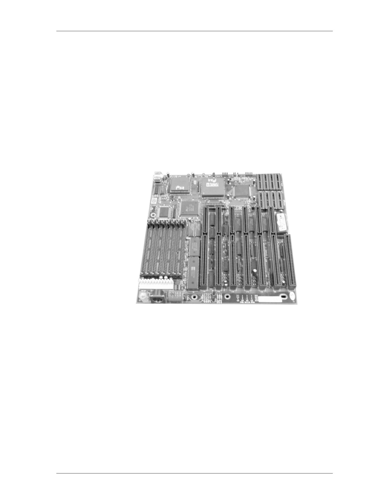
The full-size AT motherboard replaced the original IBM XT
Advanced
motherboard in 1984. It started out as a large board measuring 12
Technology (AT)
inches wide by 13.5 inches long, but later was reduced in size as
Board
advancements in design progressed. It contains two power supply
connectors that plug into one non-form molded power connector
and a combination of 16-bit and/or 8-bit ISA slots. These slots,
shown in the image below, are used to connect expansion cards to
the motherboard. They are discussed in detail in a later lesson.
Example of AT Motherboard
01/09
For Official Use Only - Law Enforcement Sensitive
C-19
Network Intrusion Responder Program
Appendix C
Motherboard Overview, continued
AT Extended
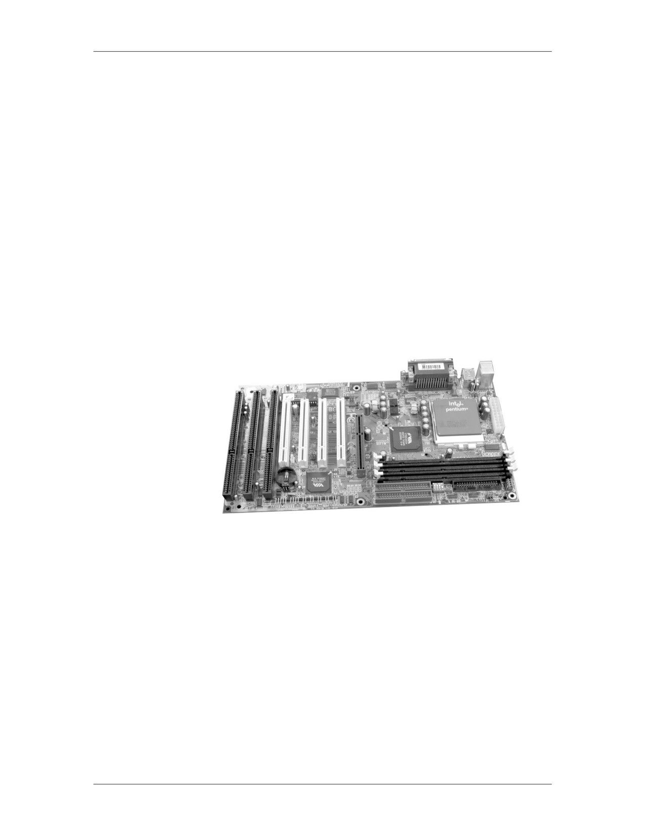
Intel introduced the ATX in 1996 as a replacement for the Baby-
(ATX) Board
AT. It was considered the first dramatic improvement in
motherboard form factors used in desktop PCs. The ATX provided
a standard, nonproprietary design that was easy to install and
maintain. Many modern motherboards use this same form factor (9
inches wide by 12 inches long.)
ATX was the first to integrate components such as the Flash BIOS
and I/O logic. The ATX motherboard is half the width of earlier
motherboards and contains combinations of ISA and PCI slots,
expansion slots that are covered in depth later in this lesson. The
power connector for the ATX is one form-molded power
connector that prevents it from being connected incorrectly.
Example of ATX Motherboard
ATX-class and above motherboards may be configured for
suspend or power-off functions that are initiated by the operating
system. This is especially true with the Microsoft Window 95 or
higher versions. During suspend, the system goes into a low power
state called a sleep mode. Contents of RAM are saved during this
state to allow the machine to wake up quickly with all running
applications remaining open. The system awakes after the mouse
or keyboard is used. During power-off, the system shuts down
completely after exiting the operating system.
C-20
For Official Use Only - Law Enforcement Sensitive
01/09
Appendix C
Network Intrusion Responder Program
Motherboard Overview, continued
The ATX Family The following motherboard form factors were developed by Intel
as evolutions of the original ATX:
Micro ATX was built as a smaller design for use in the first
small, low-cost computer systems sold in retail stores for under
$1,000. The reduced size (9.5 inches wide by 9.5 inches long)
allowed for a smaller power supply and few I/O bus expansion
slots.
Flex ATX was introduced as a smaller version of the Micro
ATX and considered the least expensive motherboard of the
ATX family. It will only support the socket-type CPU (size: 9
inches wide by 7.5 inches long).
WTX was designed as a high-performance ATX. It is a
relatively new board used in high-end servers and
workstations. It contains a flex slot that is an enlarged PCI slot
used to hold powerful multifunction cards (size: 14 inches
wide by 16.75 inches long).
01/09
For Official Use Only - Law Enforcement Sensitive
C-21
Network Intrusion Responder Program
Appendix C
Motherboard Overview, continued
Low Profile
The LPX is a semi-proprietary, non-standard design introduced by
Extended (LPX)
Western Digital in 1987. Its low-profile design incorporates slots
Board
that are parallel to the motherboard allowing the expansion cards
to plug sideways into the riser board. The riser board connects to
the motherboard. This design change allowed for slimmer PC
cases. LPX was used in PCs sold in retail stores such as Compaq
and Packard-Bell. It is easy to identify because devices are parallel
to the motherboard. Components for it are difficult to obtain. (size:
9 inches wide by 13 inches long).
Riser Board Example
New Low Profile
The NLX is a modified, non-proprietary LPX design made by
Extended (NLX)
Intel. With the NLX system, the riser plugs into the side of the
Board
motherboard. This configuration allows easy access to components
for installation and maintenance. The NLX has an integrated
network interface card (NIC).
Example of NLX Motherboard with Riser
C-22
For Official Use Only - Law Enforcement Sensitive
01/09
Appendix C
Network Intrusion Responder Program
Motherboard Components
Motherboard
The motherboard basic input/output system (BIOS), also called the
BIOS
system BIOS, is considered to be the heart of the computer
because it controls communications between computer hardware
and the operating system. System BIOS is also referred to as ROM
BIOS because the code is contained in a non-volatile, read-only
memory (ROM) chip. As opposed to typical memory chips, non-
volatile memory does not lose its contents when electricity is
removed, making the chip suitable for storing data for many years.
The system BIOS contains a software instruction set called
firmware. Firmware provides the basic input/output instructions to
boot the computer and handles several important functions
including identifying hardware currently installed in the PC,
determining which device will boot the PC, and installing basic
drivers for the keyboard, video, and disk drives prior to the
operating system loading.
The system BIOS is explained further in depth in Module 3 of this
book.
Complimentary
CMOS is a chip that stores clock settings, the current system
Metal Oxide on
configuration data as discovered by a standard Power-On Self Test
Semiconductor
(POST) or defined by the setup program, and the Plug and Play
(CMOS)
settings. Located on the motherboard, CMOS is volatile and
requires battery power to maintain the CMOS memory and system
time whether the PC is on or off. Battery power comes from one of
the following:
Coin-type watch battery (commonly used)
Brick/Barrel type battery
Capacitor, an electrical component that holds a charge
Data stored in the CMOS chip is accessed by the system BIOS and
also includes configurable settings such as boot sequence, CPU
clock speed, and power management.
01/09
For Official Use Only - Law Enforcement Sensitive
C-23
Network Intrusion Responder Program
Appendix C
Motherboard Components, continued
Chipset
The chipset controls the flow of information between various
components of the motherboard. The chipset on a modern PC
contains two or three separate chips and older PCs had as many as
five chips. The largest chip is called the North Bridge; the smaller
chip is called the South Bridge. The chipset controls many
different components of the system including:
CPU
Cache
Main memory
Peripheral Component Interconnect (PCI) bus
Industry Standard Architecture (ISA) bus
Various system resources
In addition, the chipset defines the various functions the system
will support including:
Defines Front-side Bus (FSB) speed (from 66MHz to over
1000MHz)
Supports Accelerated Graphics Port (AGP) video cards
Defines the minimum and maximum processor speed the
motherboard can handle
The major chipset manufacturers are Intel, Apollo, VIA, and SIS.
Super I/O Chip
The Super I/O chip is the chip on the motherboard that integrates
devices that were contained on expansion cards on older PCs. This
chip allows for a faster transfer rate of data between the device and
the system and has a lower failure rate. The Super I/O chip usually
contains the following devices:
Dual serial port controllers
Floppy drive controller
Parallel port controller
Keyboard and mouse controllers
C-24
For Official Use Only - Law Enforcement Sensitive
01/09
Appendix C
Network Intrusion Responder Program
Motherboard Components, continued
Jumpers
A jumper is a small plastic-covered metal clip that is placed over
metal pins sticking out of the board. When placed on the pins, the
jumper enables electricity to flow to the pins, completing the
circuit. A jumper is considered closed when the plastic clip covers
the pins.
Use of Jumpers
Use: Jumpers are used to control device settings including
processor speed and type, bus speed and CMOS password settings.
Dual Inline
Dual Inline Package (DIP) switches are small switches embedded
Package Switches
into circuit boards. They are used to configure the system
functions including the bus speed, processor speed and processor
type. DIP switches are toggled either On/Off or 1/0. Microsoft’s
standard Plug and Play feature has made the use of DIP switches
obsolete.
DIP Switch Example
01/09
For Official Use Only - Law Enforcement Sensitive
C-25
Network Intrusion Responder Program
Appendix C
Motherboard Components, continued
Trusted Platform The TPM is a microcontroller device installed on the motherboard
Module
that stores encryption keys, passwords, and digital certificates. It
provides secure key generation that can be used to create and/or
store both user and platform identity credentials for authentication.
Offers improved, hardware based security
Uses RSA and SHA-1 encryption algorithms to create an
encryption key for a specific computer
Encryption keys can be used for full-disk encryption, software
licensing, and digital rights management
Power Supply
The computer’s power supply powers all internal components.
Power supplies come in different wattage models ranging from
63.5 to 1000-plus watts. Each unit contains a power transformer
that converts voltage from the wall socket to the power level the
computer can safely use. The unit transmits a power good signal to
the motherboard. This signal must be present continuously for the
computer to run. If it is not, the computer shuts down instantly.
The power good signal performs several functions:
Prevents the computer from starting until the appropriate level
of operating voltage is reached
Interfaces with the computer’s reset switch. When the reset
switch is pressed, the power good signal is grounded out.
When the switch is released, the power good resumes and the
system reboots.
C-26
For Official Use Only - Law Enforcement Sensitive
01/09
Appendix C
Network Intrusion Responder Program
Motherboard Components, continued
ATX and AT
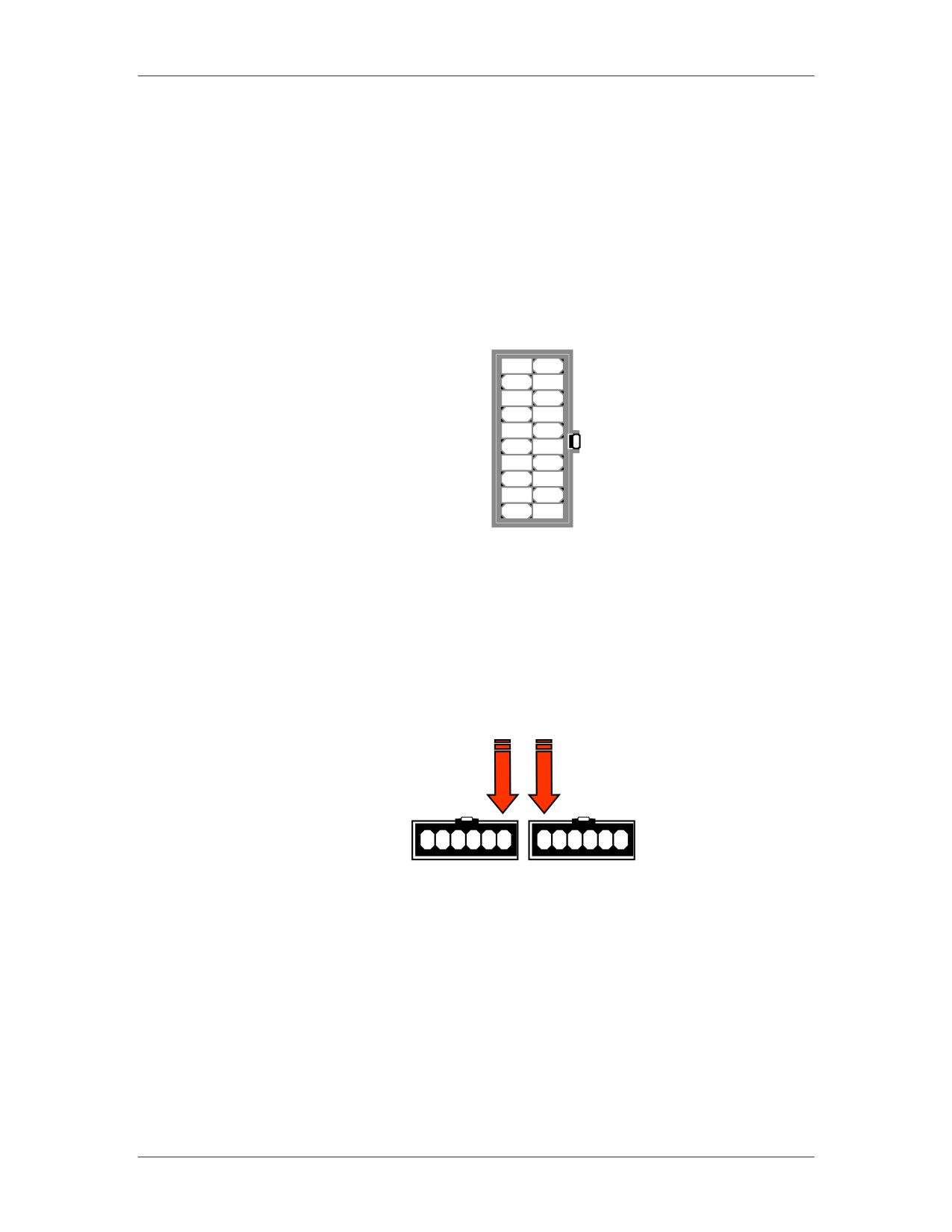
When comparing the ATX and the AT power supplies, the main
Power Supplies
plugs from the power supply to the motherboard are very different.
The ATX has a single, form-fitted plastic plug that fits into an on-
board socket that has a unique configuration. The plug is form
fitted so that it will only fit into the socket in one direction.
ATX On-Board Power Socket (front view)
In contrast, the AT power supply has two separate plugs that fit
into two separate on-board sockets. The wires on the plugs are
color-coded. To make the correct connection, be sure to place the
plugs into the sockets with the black wires of both plugs located
directly next to each other. When properly connected, these black
wires will be in the center of the two seated plugs.
AT Power Supply Socket (2 cords required)
Warning: Unlike the form-fitted ATX plug, the AT plugs can
be connected incorrectly. If the AT plugs are not
connected correctly, the motherboard will fail and a
fire may occur.
01/09
For Official Use Only - Law Enforcement Sensitive
C-27
Network Intrusion Responder Program
Appendix C
The Boot Process
Overview
All computers are designed to start in a predictable way from the
moment you press the Power On button until the moment the
operating system loads. The list below outlines the steps.
The Boot Process
Activity
Description
1. Power good signal is sent to the
When you press the
CPU
Power On button
2. CPU looks at ROM for basic
When CPU receives
instructions (BIOS)
power good signal
3. System BIOS loads
4. BIOS initiates Power-On Self Test
(POST)
5. POST checks RAM and then
Typically, a procession
Video. If either of these have a
of long single beeps for
problem, there are various beep codes.
RAM; one long and
two short for video.
From this point forward, errors are
Motherboard
reported with text messages displayed
documentation contains
on the monitor.
beep codes.
6. When RAM and Video pass the
You will begin to see
POST test, a single beep occurs. The
text on the screen. The
single beep exists simply to indicate
rapid numbers flashing
that the diagnostic speaker is working.
indicate an in-depth
A malfunctioning speaker will prevent
RAM check. The
audible beep codes.
screen will indicate the
BIOS manufacturer and
version number.
7. POST then checks keyboard.
If an error occurs, a
text message generally
displays the on-screen
8. Legacy and then Plug and Play
The data gathered is
devices are identified
then stored on the
CMOS chip
9. CMOS data is queried against new
If there is a problem
current configuration data. Drives
with the CMOS
spin, lights flash, and sounds are
battery, you will get a
heard.
text message.
10. Finding no major hardware errors,
BIOS turns the process over to the
boot loader.
C-28
For Official Use Only - Law Enforcement Sensitive
01/09
Appendix C
Network Intrusion Responder Program
The Boot Process, continued
Overview,
Activity
Description
continued
11. The boot loader learns the boot
sequence from the BIOS (e.g. A: C:
CD-ROM, etc.) and looks for the
Master Boot Record (MBR) on that
device.
For hard disks, the boot loader looks
for a partition table. The partition
table will have a pointer to the MBR
on the primary, active partition
12. The MBR contains the first file
needed to start the operating system
(IO.SYS in Windows 9x, boot.ini in
NT).
13. The whole process is turned over
to the OS and you see splash screens,
etc.
01/09
For Official Use Only - Law Enforcement Sensitive
C-29
Network Intrusion Responder Program
Appendix C
Bus Overview
Introduction
The various buses comprise the transportation system within every
computer. It acts as a highway that sends data, signals, and power
among the processor, memory, and other components. In general,
there are two bus categories: the internal bus that connects all the
internal components to the CPU and main memory and the
expansion bus that connects expansion boards to the CPU and
main memory.
A computer has several different types of buses. The key buses
found in many computers include:
Processor bus
Memory bus
Accelerated Graphics Port (AGP) bus
Peripheral Component Interconnect (PCI) bus
PCI Express
Industry Standard Architecture (ISA) bus
Universal Serial bus (USB)
External SATA (E-SATA)
Bus Architecture
Buses are made up of a complex system of thin circuits known as
traces that are located on any of the several layers of the
motherboard. The system chipset orchestrates data transfer from
all components via the bus. In addition to circuits, the bus also
includes microchips and slots to hold expansion cards or circuit
boards.
Buses are hierarchically arranged so that each slower bus is
connected to the faster bus above it. The bus size, called width,
describes the amount of data (measured in bits) that can be
transmitted at one time. The bus’s clock speed, measured in MHz,
describes the speed of data transfer.
Processor and
The processor bus is the data pathway between the CPU and the
Memory Buses
motherboard chipset. Also called the front side bus, the processor
bus is the fastest bus on the motherboard. It is used by the CPU to
transfer information between cache or main memory and the
chipset.
The memory bus is the data pathway between RAM and the CPU.
It is always the same width as the processor bus.
C-30
For Official Use Only - Law Enforcement Sensitive
01/09
Appendix C
Network Intrusion Responder Program
Bus Types
ISA Bus
The ISA bus was part of the first IBM PC in 1984. This early
version was 8 bits with a speed of 5 MHz. Today, the ISA bus still
remains slow at 16 bits and 8 MHz, which is ideal for slow-speed
peripherals such as some older modems and sound cards. Until
recently, most motherboards contained several ISA slots for
backward compatibility. Newer motherboards have replaced ISA
slots with a PCI bus.
Extended ISA Bus The Extended ISA (EISA) bus is a 32-bit, non-proprietary slot
connection designed to replace the ISA bus. This bus accepts ISA
devices and has two slots. These slots are usually brown in color.
The EISA bus is now obsolete in PCs, but they are still used in
high-end servers.
Micro Channel
The Micro Channel Architecture (MCA) connector was an IBM
Architecture
proprietary slot connection designed to replace the ISA/EISA
cards. The MCA system is now obsolete, but may still be found in
older IBM computer systems. MCA introduced the concept of
busmastering. This concept allows devices direct access to the
CPU via the motherboard I/O controller for faster access.
Busmastering is still used by modern devices. There are two
formats: 16-bit with two slots and 32-bit with three slots (third slot
is separated from the other two slots).
MCA 16-bit bus (2 slots)
MCA 32-bit bus (3 slots)
01/09
For Official Use Only - Law Enforcement Sensitive
C-31
Network Intrusion Responder Program
Appendix C
Bus Types, continued
Video Electronic
The Video Electronic Standards Association (VESA) local bus
Standards Assoc.
(VL-Bus) is a 32-bit, non-proprietary slot connection meant to
Local Bus
replace the ISA bus. It has three slots (two together and one
separated). The first two slots (ISA) are black and the third
parasitic slot is brown. It is used for older video cards and was
replaced by the PCI bus.
Example of VL-Bus
C-32
For Official Use Only - Law Enforcement Sensitive
01/09
Appendix C
Network Intrusion Responder Program
Bus Types, continued
PCI and
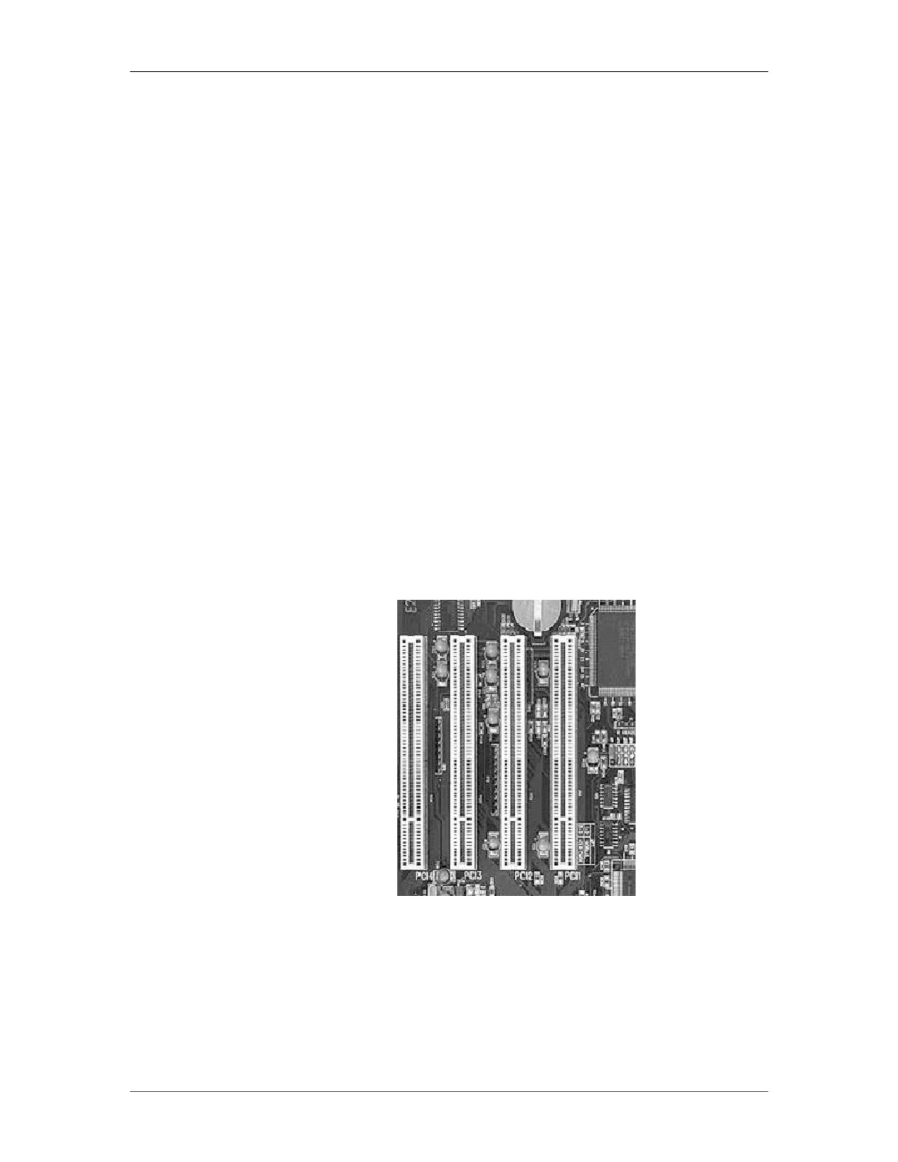
PCI bus is a collection of 32-bit or 64-bit connector slots on the
PCI-X Bus
motherboard, generally white in color. Modems, NICs, SCSI host
adapters, and non-AGP video cards use the PCI bus. The PCI local
bus is also called a mezzanine (meaning intermediary) bus because
it sits in the middle between the CPU and RAM. It’s part of the
North Bridge and can function with other devices and RAM
without the use of the CPU.
PCI and PCI-X send data in parallel form in one direction at a time
in speeds ranging from 33MHz (PCI) to 533MHz (PCI-X) with a
maximum of 34Gbits/sec transfer in the most recent PCI-X. All
devices on a PCI bus take turns accessing this bandwidth.
PCI-X is completely backward compatible. All 32-bit PCI cards
will function in a PCI-X slot and new 64-bit PCI-X cards will
function in a standard PCI slot from the late 1990s. While popular
in server environments, PCI-X should not be confused with the
newest bus implementation, PCI-Express.
Example of PCI and PCI-X Bus
01/09
For Official Use Only - Law Enforcement Sensitive
C-33
Network Intrusion Responder Program
Appendix C
Bus Types, continued
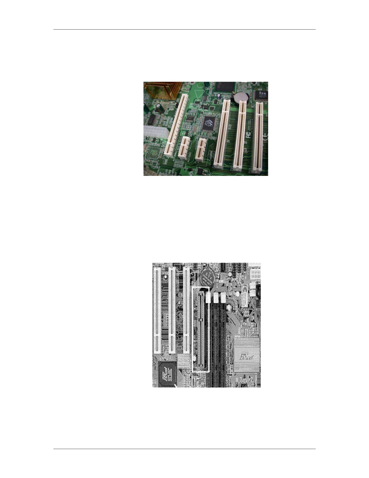
PCI Express
PCI Express is a PCI advancement that sends data across lanes in
serial form and is capable of sending and receiving data
simultaneously. There are various formats of PCI Express such as
x1, x2, x4, x8, x12 and x16. The number, when multiplied by four,
represents the number of lanes available to send and receive data.
For instance, the x2 has 8 available lanes and the x16 has 64 lanes.
In addition to multiple lanes, PCI Express introduces lane
switching which allows data to be switched along lanes as needed
instead of all devices taking turns waiting for the bus. This makes
PCI Express much more efficient than PCI or PCI-X. PCI Express
is also known as 3GIO or 3rd generation input/output.
The most common formats are x1 and x2 for general peripheral
devices and x16 as an AGP replacement for graphics cards. The
x16 format can provide up to 128 Gb/sec throughput.
PCI Express connectors, generally black in color, are physically
different from PCI and are not backward compatible with PCI or
PCI-X. It is expected that motherboards will contain some
combination of PCI and PCI Express for the next few years as the
industry makes the transition to all PCI Express.
Examples of PCI Express
1X
4X
8X
C-34
For Official Use Only - Law Enforcement Sensitive
01/09
Appendix C
Network Intrusion Responder Program
Bus Types, continued
PCI Express,
continued
AGP Bus
The AGP bus is used exclusively for high-speed graphics
processing. This 66 MHz bus has a 32-bit slot connection that is
brown in color. It is reserved for a video card. The AGP bus is
available in 1x, 2x, 4x and 8x transfer rates. The AGP local bus is
placed near the processor bus for direct access to it.
Example of AGP Bus
01/09
For Official Use Only - Law Enforcement Sensitive
C-35
Network Intrusion Responder Program
Appendix C
Bus Types, continued
USB
The USB has a port connection often located at the rear of the
computer. Most computers have a USB port that is used to connect
various types of peripherals to the computer system. USB brings
Plug and Play capabilities to peripherals connected outside the PC.
These peripherals are automatically configured when attached to
the USB port and a reboot is not necessary to use the component.
Example of USB Ports
Theoretically, you can daisy chain (connect various devices to
each other in series) 127 devices to each USB port. However, in
reality any more than five devices require a USB hub. The current
USB specification, version 2.0, supports a data transfer rate of 480
Mb/sec. Version 2.0 is backward compatible with earlier versions
1.1 and 1.0 that used 12 Mb/sec. and 1.5 Mb/sec. rates.
USB is a continually evolving technology, as evidenced by the
announcement of USB 3.0. USB 3.0 increases the speed rating of
external devices by ten times that of USB 2.0, transferring data at
4.8 Gb/sec. USB 3.0 will be fully compatible with 2.0 and 1.1
devices.
In addition to wired USB solutions, there are recent innovations in
Wireless USB (WUSB). WUSB allows for USB 2.0 speeds to
devices within three meters of a computer. Wireless USB works
similarly to Bluetooth, but features a reduced range to support
higher transfer speeds.
C-36
For Official Use Only - Law Enforcement Sensitive
01/09
Appendix C
Network Intrusion Responder Program
Bus Types, continued
Proprietary Bus
You need to be aware of several proprietary bus connectors. These
Connectors
are explained here.
IEEE 1394
The IEEE 1394 is an alternative to a USB port. Brand names for
(FireWire)
this connector are FireWire by Apple and i.Link by Sony. It allows
63 devices to be daisy chained (connected) to each connector. It
can also handle multiple chains. The transfer rate is approximately
400 Mb/sec, which is faster than the USB 1.1 but slower than USB
2.0 480 Mb/sec. There is also a 1394b standard that allows faster
signaling, up to 3.2 Gb/sec., and requires special cables and
interfaces.
1394a (FireWire 400)
1394 and 1394a are the original implementations of this bus type,
with speeds up to 400 Mb/sec. 1394a uses two styles of
connectors: a 4-pin connector and a 6-pin connector, shown below.
The 6-pin has become a standard in many computers and external
devices.
IEEE 1394 Connector Example
1394b (FireWire 800)
1394b was designed as a higher performance bus type, allowing up
to 800 Mb/sec and greater cable distances. However, 1394b
requires a completely different cable and connector, a 9-pin
connector that resembles the 4-pin connector shown above. While
there are great benefits to 1394b, it has not completely overtaken
the original 1394a. Many modern devices feature both 1394a and
1394b connectors.
Firewire S3200
S3200 refers to a newer FireWire standard that uses existing 1394b
cables to achieve data transfer rates of 3.2 Gb/sec, four times that
of FireWire 800.
01/09
For Official Use Only - Law Enforcement Sensitive
C-37
Network Intrusion Responder Program
Appendix C
Bus Types, continued
E-SATA
The E-SATA is an external port connection for external SATA
devices, such as hard drives or DVD/CD devices. E-SATA runs at
speeds of 300 Mb/sec.
Example of E-SATA Cable and Ports
C-38
For Official Use Only - Law Enforcement Sensitive
01/09
Appendix C
Network Intrusion Responder Program
Lesson 4 - CPU and Memory
Introduction
The computer’s processor, called the central processing unit
(CPU), works in concert with memory to process software and
user commands. This lesson explains the significance and
functions of both CPU and memory.
Purpose of this
You should understand how a computer processes commands and
Lesson
data. You will be presented with information about CPUs and
memory to enhance your general knowledge of computer systems.
Objectives
After successfully completing this lesson, you will be able to:
Explain the basic functions of the CPU
Identify the CPU in a computer
Recognize various types of memory
In this Lesson
The following table shows the contents of this lesson.
Topic
See Page
CPU Functions
C-40
Memory
C-41
01/09
For Official Use Only - Law Enforcement Sensitive
C-39
Network Intrusion Responder Program
Appendix C
CPU Functions
CPU Defined
The computer processor, or CPU, is the main component that
processes all software instructions and makes all calculations.
The CPU’s main components are the following:
Arithmetic logic unit that handles all arithmetic and logical
operations
Control unit that takes instructions from memory, translates
them, and then carries out the instructions.
The CPU can be either a single-socket chip or a chip that is
mounted on a slot circuit board.
Types of CPUs
There are various types of CPUs from several manufacturers. Each
type connects to the motherboard in different ways. Some CPUs
connect via a socket in the motherboard and others use a slot
connector. Each style of connector is produced in a variety of
specific and unique designs, few of which are compatible with
each other. A CPU and a motherboard must be completely
compatible for a computer to operate.
Socket-type CPUs were the original design and is still the most
popular. The actual CPU chip attaches to the motherboard through
a pin-grid array (PGA), a square receiver containing hundreds of
evenly spaced holes. Modern Intel CPUs are designed as Plastic
PGA (PPGA) or Flip-Chip PGA (FCPGA). The only physical
difference between these is the orientation of the actual processor
chip in relation to the motherboard.
During the late 1990’s many CPUs were designed using a slot-type
connector. Similar to a PCI card, the CPU would seat into a
rectangular slot on the motherboard. However, this design was
inefficient for faster clock speeds and the design was phased out.
The Pentium II and many Pentium III processors were designed as
slot CPUs.
C-40
For Official Use Only - Law Enforcement Sensitive
01/09
Appendix C
Network Intrusion Responder Program
Memory
Introduction
Memory is the temporary data storage area of a computer system.
It is the system’s workspace that houses the programs and data
being processed by the CPU. The two main types of memory are:
Read-only memory (ROM) is non-volatile and cannot be
written to. The ROM chip contains the motherboard BIOS that
is used to boot the system.
Random access memory (RAM) is the main memory that can
be read by the CPU and written to. RAM is temporary because
it relies on electrical power. RAM is also referred to as
physical memory that is represented by the actual computer
chips that hold data.
Memory is often confused with disk storage (on hard drives, disks,
or tapes) because both are measured in megabytes and gigabytes.
To remember the distinctions between memory and disk storage,
consider this analogy. RAM represents your current work files on
your desk that are easily accessible when you want to make
changes to them.
Conversely, disk storage represents an area where you
permanently store completed work files, such as in a file drawer.
You access those files less frequently and you must do a search to
retrieve them.
01/09
For Official Use Only - Law Enforcement Sensitive
C-41
Network Intrusion Responder Program
Appendix C
Memory, continued
ROM
There are four types of ROM chips as detailed below. All types
use non-volatile data storage meaning that the data remains
indefinitely on the chip until the chip is reprogrammed using
special hardware or software.
ROM: During manufacturing, binary data is stored in the die of
the silicon and cannot be changed without making a new chip.
Programmable ROM (PROM): This chip comes blank and
needs to be programmed using a special machine called a
device programmer. Once the PROM is written to, it cannot be
changed.
Erasable PROM (EPROM) - A type of ROM that can be
erased by exposing it to high-intensity ultraviolet light. The die
used is sensitive to ultraviolet light. When exposed, all the
binary 0s are changed back to 1s.
Electrically Erasable PROM (EEPROM) or FLASH ROM:
Chips that can be electrically erased and reprogrammed on the
circuit board using a special software program. No other
special equipment is required to reprogram the chip. All
modern MBs use this type of chip for the system board BIOS.
RAM
RAM is short-term memory used to store data being processed by
the CPU. RAM is volatile because any data that is stored in RAM
is cleared when the power is off or the system is reset. RAM chips
are mounted on sticks that fit into connection slots on the MB.
Slots are arranged in numbered banks starting at 0. Bank 0 is
usually located near the CPU.
C-42
For Official Use Only - Law Enforcement Sensitive
01/09
Appendix C
Network Intrusion Responder Program
Memory, continued
Dynamic RAM
DRAM is the most common and least expensive memory chip. It
(DRAM)
is small and has high data density (up to 256K). Other
characteristics include:
Several DRAM chips are mounted on a single stick that fits
into connection slots on the MB.
Connection slots are arranged in banks starting at 0. Bank 0 is
usually located near the CPU.
DRAM requires constant electrical refreshing to keep it dynamic.
This is done by using capacitors and transistors in pairs. Capacitors
hold charges (both positive and negative) that indicate whether the
transistor is On or Off. The charge holds power in the transistor
and keeps the RAM contents alive.
01/09
For Official Use Only - Law Enforcement Sensitive
C-43
Network Intrusion Responder Program
Appendix C
Memory, continued
Single Inline
SIMM sticks were used in earlier generation PCs. Manufactured in
Memory Modules
sizes ranging from 512 KB to 32 MB, they were manufactured
(SIMM)
with flat connection pins in two types:
1.
30-pin SIMM, considered obsolete in PCs (used with 386
processors and below), is installed in pairs
2.
72-pin SIMM is still available and is installed in singles on
motherboards with CPUs below Pentiums and in pairs on
Pentiums and above. These were widely used a few years ago
until they were replaced by DIMMs.
Example of SIMM Chip
A SIMM has a unique insertion method and locking mechanism.
SIMMS are inserted into the connector slot at a 45-degree angle
and then rotated into the slot. The locking mechanisms are small
metal or plastic pins located on the side of the slots. You know the
module is a SIMM if you remove it at a 45-degree angle.
C-44
For Official Use Only - Law Enforcement Sensitive
01/09
Appendix C
Network Intrusion Responder Program
Memory, continued
Dual Inline
The most widely used memory modules are the 168-pin DIMMs,
Memory Modules
which have replaced SIMMs. They are 64 bits wide and range in
(DIMM)
size from 8 MB to 1 GB. DIMMS are inserted straight into their
sockets and locked in place.
Synchronous
SDRAM is the modern memory standard and is faster than regular
DRAM (SDRAM)
DRAM. It is most prevalent in Pentium II/Athlon systems and
above. SDRAM runs in synchronization with the actions of the
processor bus. It performs operation at the same time as the system
clock and at the same speed. This increases the speed of the data
input/output. All SDRAM are DIMMs. All DIMMs are not
necessarily SDRAM.
SDRAM is manufactured at single, double data rate, or quad data
rate (SDR, DDR, DDR2 and DDR3). These rates describe the
speed of data transfer per clock cycle. There are several SDRAM
speeds. Which type and speed your system requires depends on the
motherboard.
The following lists various SDRAM speeds and their associated
processor bus speeds:
SDRAM Speed
Associated Processor Bus Speed
PC 66
66 MHz
PC 100
100 MHz
PC 133
133 MHz
PC 2700
333 MHz
PC 3200
400 MHz
PC 4200
533 MHz
PC 5300
667 MHz
PC 6400
800 MHz
PC 10666
1333 MHz
PC2 8500
1066 MHz
PC3 12800
1600 MHz
PC3 14900
1866 MHz
01/09
For Official Use Only - Law Enforcement Sensitive
C-45
Network Intrusion Responder Program
Appendix C
Memory, continued
Synchronous
When upgrading SDRAM, it is important to select speeds that are
DRAM (SDRAM),
greater than or equal to the frontside (processor) bus speed.
continued
Pushing slower RAM at higher speeds (overclocking) will cause
the RAM to overheat and malfunction, which can also cause
permanent damage to the motherboard. It is acceptable to install
faster RAM into a slower motherboard. SDRAM is not compatible
with all motherboards, so it is important to refer to the
motherboard documentation.
RIMM (RAMBUS
RIMMs are found in high-end computers because they offer the
Inline Memory
highest performance of available memory, with transfer speeds
Modules)
capable of over 6 GB/s. The memory modules use RAMBUS
Dynamic RAM (RDRAM) chips, a proprietary chip format. These
are generally geared towards the server market, but Intel actively
pushed the technology towards the consumer market. Due to their
high cost, they are uncommon on most computers.
Example of RIMM Chip
RIMMS are manufactured with 184 connection pins and in sizes
that range from 64 MB to 1 GB. Most motherboards require that
RIMM chips be installed in pairs. If only a single memory module
is needed, then a special continuity unit (CU) is required to
provide termination. CUs are additional RIMM modules without
the RDRAM chips that are plugged into the remaining RIMM slots
not occupied by memory modules.
C-46
For Official Use Only - Law Enforcement Sensitive
01/09
Appendix D
Network Intrusion Responder Program
Module D
Data Storage Components
Overview
Understanding the vast array of data storage components is vital
knowledge for processing an electronic crime scene investigation.
This module introduces disk drives and various types of removable
storage media.
Purpose of this
The purpose of this module is to introduce students to the various
Module
types of media available for the storage of digital data.
Objectives
After successfully completing this module, you will be able to:
Explain how data is stored on a hard drive
Identify components of the hard drive
Discuss the workings of a floppy drive
Recognize various removable media
In this Module
Here are the lessons in this module:
Lesson
See Page
Lesson 1 - Hard Disk Drives
D-3
Lesson 2 - Floppy Drives and Removable Media
D-35
01/09
For Official Use Only - Law Enforcement Sensitive
D-1
Network Intrusion Responder Program
Appendix D
This page intentionally left blank.
D-2
For Official Use Only - Law Enforcement Sensitive
01/09
Appendix D
Network Intrusion Responder Program
Lesson 1 - Hard Disk Drives
Introduction
Hard drives are the main storage of the computer. Drives use
highly sophisticated technology to write data on platters. This
lesson examines the main components of hard drives and their
functions. It also introduces you to data storage methods.
Purpose of this
In this lesson, you will learn how disk drives store information.
Lesson
This is important to knowing how to safeguard data during a crime
investigation.
Objectives
After successfully completing this lesson, you will be able to:
Identify the main components of a hard drive
Explain the process by which data is stored on and retrieved
from a hard drive
Describe the basic formatting procedures for hard drives
Explain hard drive geometry
In this Lesson
The following table shows the contents of this lesson:
Topic
See Page
Hard Drive Overview
D-4
Hard Drive Components
D-5
Hard Drive Controllers
D-11
Hard Drive Geometry
D-17
RAID
D-19
Drive Preparation
D-22
Hard Drive Preparation
D-24
01/09
For Official Use Only - Law Enforcement Sensitive
D-3
Network Intrusion Responder Program
Appendix D
Hard Drive Overview
Saving a File to a
To understand how the hard drive works, you first need to know
Hard Drive
how a file is saved to it. As a file is being written or created, all of
its contents are temporarily stored within RAM. When you save
the file, the software program you are using makes a request to the
operating system to take the file from RAM and store it
permanently to the hard drive. Your request to save a file initiates
a complex process that records your file and tracks its storage
location on the hard drive.
Process for Storing
For illustration purposes, the following table describes the general
Data on a Hard
process for saving a file to a hard drive in modern operating
Drive
systems.
Step
Activity
1
The user makes a request to save a file. That file is then
temporarily stored in RAM (if not already residing
there).
2
The file system analyzes the disk to find the required
available space.
3
The operating system receives the request to transfer the
file from RAM to permanent storage on disk.
4
The file system (FAT, VFAT, FAT32, NTFS, ext2 or
ext3) updates the file directory with the newly saved file
name and its exact location or directory path.
5
The operating system tells the drive controller to save
the file. The file is then transferred from RAM to the
hard drive.
6
Once the file is saved, the file system marks that area of
the disk as not available. That area cannot be
overwritten by subsequent file saves.
D-4
For Official Use Only - Law Enforcement Sensitive
01/09
Appendix D
Network Intrusion Responder Program
Hard Drive Components
Components
Hard drives contain the following components:
Disk platters
Read/write heads
Head actuator
Spindle motor
Jumpers and/or switches
Disk controller
Cables and connections
Disk Platters
A hard drive stores archival copies of all programs and data on
non-volatile disk platters made of metal or glass with a magnetic
medium coating. Most hard drives can hold several 3.5-inch
platters with a current capacity of 250 GB or higher. Laptops and
notebook computers use 2.5-inch platters with a current capacity
of 100 GB each. Data is stored on both sides of each disk platter.
When in operation, the disks spin and the read/write heads move
over the disks and store information in tracks and sectors. Data is
stored in concentric rings or tracks on the disks. The tracks are
divided up into segments called sectors. Each sector can store
approximately 512 bytes of data.
01/09
For Official Use Only - Law Enforcement Sensitive
D-5
Network Intrusion Responder Program
Appendix D
Hard Drive Components, continued
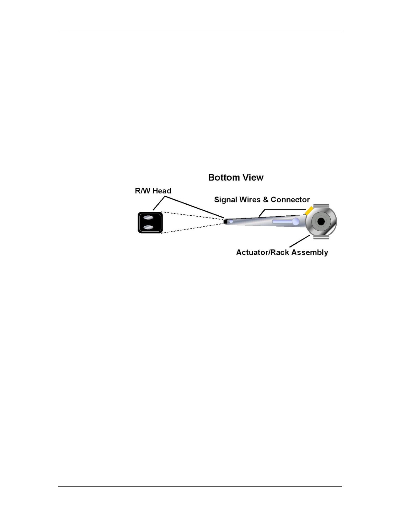
Read-Write Heads Read-write heads are the mechanisms that store and read data on
platters. There is one read-write head combination for each side of
the disk platter and all heads are mounted on a single rack. Heads
move in unison across the platters. They float above the surface of
the disk platter on a cushion of air generated by the action of the
spinning disk platter. The heads float three to five millionths of an
inch above the platters. As they move, the heads read changes in
the disk’s magnetic coating, called magnetic flux. This is the
process for interpreting stored data.
Data is stored on both sides of the platters. Side numbering starts
at zero for the top side of the top platter. For example, if the drive
has four platters (eight sides), the numbering for the sides would
be zero through seven.
D-6
For Official Use Only - Law Enforcement Sensitive
01/09
Appendix D
Network Intrusion Responder Program
Hard Drive Components, continued
Jumpers
A jumper is a set of pins used to control device settings. The pins
act like an on/off switch and are configured by placement of a
small plastic block, called a shunt. When there is no shunt over the
jumper pins, the circuit is open, or off. When there is a shunt
placed over the pins, a small wire inside the shunt connects the
pins and the circuit is closed, or on. This is also called shorted. A
shunt can also be attached to a single pin in a parked position. This
does not close the circuit; the parked position is simply used to
store shunts that are not currently needed.
You use jumpers when installing PATA (Parallel ATA) IDE
devices. Typical motherboards house two PATA IDE channels that
are identified by a Primary (IDE 1) Connector and a Secondary
(IDE 2) Connector. Each IDE channel can support a maximum of
two IDE devices. The relationship of the two devices on a single
channel is master and slave, which simply designates the
sequential order of the two devices. The four possible IDE device
relationships are:
Primary Master: Device 1 on the primary IDE 1 channel
Primary Slave: Device 2 on the primary IDE 1 channel
Secondary Master: Device 1 on the secondary IDE 2 channel
Secondary Slave: Device 2 on the secondary IDE 2 channel
The designation of master and slave between two devices on the
same IDE channel is determined by jumper settings on the IDE
devices. The drive normally contains a diagram indicating which
pins to short and which to leave open. The purpose of setting
drives on one connector or another, and choosing between master
and slave, is to place the drives within a specific order. On modern
computers, drives are read by the operating system in order from
primary master down to secondary slave. Therefore, a drive placed
earlier in the chain will have a lower drive letter.
Some motherboards support cable select (CS) technology. By
setting the drive’s jumpers to CS and using a special CS cable, you
can control the master and slave designations of the drives’
placement on the cable. Standard master and slave settings as
described above are used more frequently than CS.
01/09
For Official Use Only - Law Enforcement Sensitive
D-7
Network Intrusion Responder Program
Appendix D
Hard Drive Components, continued
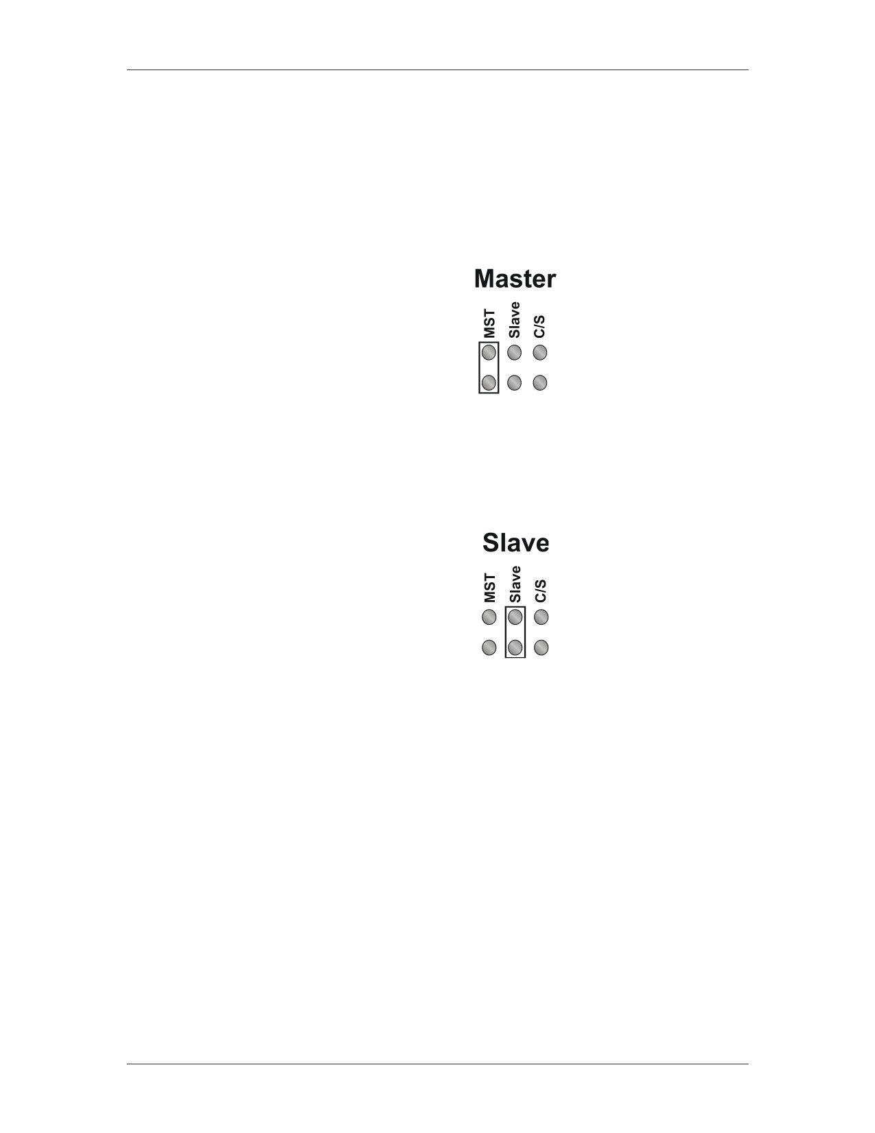
Jumpers, continued Setting the Master Drive
To indicate a primary hard drive in a series of two, close the
Master jumper for the following configuration:
Setting the Slave Drive
To indicate a secondary hard drive in a series of two, close the
Slave jumper for the following configuration:
Note that on newer motherboards, with support for SATA (Serial
ATA) devices, the motherboard may have only one PATA
connector or none at all. Additionally, SATA devices do not
require a jumper for Master and Slave settings, as each device is
plugged onto its own motherboard connector.
D-8
For Official Use Only - Law Enforcement Sensitive
01/09
Appendix D
Network Intrusion Responder Program
Hard Drive Components, continued
PATA Data Cables Older PATA IDE hard drives and CD-ROMs connect to the
motherboard via a ribbon cable to facilitate data transfer. These
cables are flat and wide with wires running in parallel the length of
the cable. IDE ribbon cables generally have three 40-pin
connectors: one to attach to the motherboard and one each for
Master and Slave device. A red or black stripe along one edge of
the cable indicates the location of Pin 1 and is used to determine
cable orientation.
40-pin Ribbon Cable
Connections on devices such as hard drives and the motherboard
are usually notched or fitted so that the ribbon cable can only
attach one way. If not connected correctly, the device will not
work and damage may occur. Always attach the ribbon cable on
IDE devices with the red (or black) stripe closest to the power
connection.
01/09
For Official Use Only - Law Enforcement Sensitive
D-9
Network Intrusion Responder Program
Appendix D
Hard Drive Components, continued
SATA Data Cables SATA (Serial ATA) is a communication bus technology that is
replacing older PATA (IDE) technology. SATA, unlike PATA,
does not use Master and Slave jumpers on the hardware to
determine device priorities. Instead, each SATA device has its own
dedicated connection to the host device. Therefore, no bandwidth
is shared with any other devices over the SATA data cables.
SATA offers other benefits over PATA, such as more compact
cables for better airflow, and hot swapping capabilities.
SATA data cables use 7-pin connectors that only utilize four wires
for transferring data. The other three wires are used as ground.
SATA Data Cable
A new power connector is also specified by the SATA standard,
although many SATA devices include both SATA and Molex
power connectors. This cable is designed with 15-pins and
supports three different voltages: 3.3 V, 5 V, and 12 V. Nine of the
15 pins are used for power, five are used for ground, and the last
pin is used for staggered spinup. Staggered spinup allows the
drives to initialize and power up sequentially to increase reliability
and prevent power surges.
SATA Power Cable
D-10
For Official Use Only - Law Enforcement Sensitive
01/09
Appendix D
Network Intrusion Responder Program
Hard Drive Controllers
Drive Controllers Computer storage devices including hard drives and floppy drives
require controllers to govern how they operate. A controller is a
device that handles the transfer of data between the component and
the computer. The disk drive controllers that will be discussed in
this course include the following:
Integrated Drive Electronics (IDE)
Enhanced IDE (EIDE)
Serial ATA (SATA)
Small Computer System Interface (SCSI)
Serial Attached SCSI (SAS)
Integrated Drive
Integrated Drive Electronics (IDE) is a term used to describe any
Electronics (IDE)
disk drive with a built-in controller. The technical name for IDE is
Controller
Advanced Technology Attachment (ATA) IDE. The IDE is the
primary interface electronics (controller) that connects a hard disk
drive to the computer.
With today’s technology, IDE is integrated into the drive. The
drive attaches to a connector on the MB. IDE makes the drive
more reliable than drives that have separate ISA slotted
controllers. This reliability enhances the integrity of data.
IDE controllers are customized to fit the IDE drive. In contrast,
separate drive controller cards are generic and may not provide full
speed or functionality. IDE controllers contain an independent
BIOS that limits the total hard drive size to 528 MB. It uses a
standard 40-pin ribbon cable to connect the drive to a
motherboard.
IDE Controller Connection
Note: If you seize a drive attached to a legacy controller card, be
sure to take the controller card as well as the drive to ensure
that you can access the disk.
01/09
For Official Use Only - Law Enforcement Sensitive
D-11
Network Intrusion Responder Program
Appendix D
Hard Drive Controllers, continued
Enhanced IDE
Enhanced IDE (EIDE) controllers offer enhanced controller BIOS
Controller
that increases maximum drive capacity to more than 528 MB. This
controller’s technical names are Advanced Technology
Attachment series ATA-2 through ATA-6. It is marketed as Fast
ATA and Fast ATA2. All ATA series drives are backward
compatible with older models.
EIDE provides two data channels per connector; therefore, two
drives can be connected to each EIDE port. In addition, EIDE
allows attachment of Advance Technology Attachment Packet
Interface (ATAPI) devices, including CD-ROM, DVD, and Zip
drives.
ATA-1, 2, and 3 Controllers
Use the CPU for data transfer (PIO mode) which takes CPU
transferring time away from other tasks
Data transfer rates: ATA-1 is 8 MB/sec; ATA 2 and ATA-3 are
16 MB/sec
ATA-4, 5 and 6 Controllers
Uses Direct Memory Addressing (DMA) modes for data
transfer. During DMA transfer, the CPU is not used.
ATA-4 support a transfer rate of up to 33 MB/sec
ATA-5 supports transfer rates of up to 66 MB/sec
ATA-6 supports transfers rates of up to 100 MB/sec
To achieve rates of speed of 66 MB/sec or more, a special 40-
pin, 80-wire ribbon cable must connect the hard drive to the
motherboard.
PATA Naming
While ATA, IDE, and EIDE technically refer to three separate
Convention
concepts, they are generally grouped together and referred to as the
same technology. Many times, the terms are used interchangeably
to refer to hard drives, with the exceptions of SCSI and SATA.
Since the introduction of SATA (Serial ATA), all examples of
prior hard drives have been retroactively renamed to PATA
(Parallel ATA).
D-12
For Official Use Only - Law Enforcement Sensitive
01/09
Appendix D
Network Intrusion Responder Program
Hard Drive Controllers, continued
Serial ATA
The two-inch wide parallel PATA ribbon cable has reached a
(SATA)
maximum transfer rate of 133 Mbps (megabytes per second),
marking its technical limitations. As a need grew for higher
performance hard disks, the Serial ATA (SATA) standard was
introduced and implemented. SATA currently has speeds of 150
Mbps (SATA 1.5G) and 300 Mbps (SATA 3G) and has the
potential to go up to 600 Mbps (SATA 6G). Serial ATA’s power
requirements, 250 millivolt versus PATA’s 5 volt, have made it
widely adopted in new low-power motherboards.
Serial ATA drives are connected via a .25-inch cable that connects
the drive to a Serial ATA card plugged into a PCI slot or a slot
integrated onto the motherboard. The SATA cables have seven
pins and seven wires. The thinner cables permit better airflow and
are smaller and easier to route. Parallel ATA cables are two inches
wide and have a maximum length limitation of 18 inches. The
SATA cable has a maximum length limitation of one meter.
Each SATA connection supports a single drive. As previously
mentioned, this means that you no longer set jumpers for the
master or slave configuration. The SATA standard also has hot
swapping designed into its configuration which allows you to swap
drives while the system is running.
SATA hard drives also feature a unique SATA power connector.
Unlike the standard Molex 4-pin connector typically found in PCs,
the SATA power connector features 15 pins to provide 3.3 volt, 5
volt, and 12 volt power, depending on a device’s needs. Many
current SATA hard drives support both SATA Molex power
connectors; however, the SATA power connector is required to
take advantage of hotswapping.
SATA channels and drives are not inherently backward compatible
with IDE technology, although there are SATA-to-IDE adapters
available.
01/09
For Official Use Only - Law Enforcement Sensitive
D-13
Network Intrusion Responder Program
Appendix D
Hard Drive Controllers, continued
External SATA
To handle the growing market of external storage devices, eSATA
(eSATA)
was designed to provide high-performance data transfers to
portable devices. The external SATA connection allows for SATA
drives to be connected externally with transfer speeds up to 300
Mbps, which is six times faster than USB 2.0. The eSATA
shielded cables are found in lengths up to two meters, but do not
provide power to the end device. While eSATA is currently geared
towards external SATA hard drives, it is able to accommodate a
large variety of external devices, including CD-ROMs.
Small Computer
SCSI is a system level interface that enables the connection of
System Interface
various peripheral devices to the computer. Most modern home
(SCSI)
PCs do not come with SCSI hardware preinstalled. However, any
computer with a PCI slot can become SCSI compatible.
SCSI is not a controller like IDE. Instead, it is a separate data bus
that is connected to the system bus via a host adapter. There are
some high-end computers that have a SCSI adapter card or an
adapter built into the MB.
Many current SCSI busses can support between 8 and 16 devices,
although support for one device is lost to the host adapter. Other
SCSI implementations can support many more devices, such as
SSA which supports 96 and SAS (Serial Attached SCSI) which
supports 16,256. Devices are strung together in a chain and each
device is assigned a SCSI ID. A typical SCSI host adapter can
support a maximum of 16 devices, although the actual SCSI
adapter counts as one of those 16 devices. When one device wants
to communicate with the system bus, the data passes through the
host adapter to the system bus.
Because the SCSI bus operates like a chain, it must have
termination at the end the chain. Most computers can support up to
four host adapters.
A SCSI bus can be either 8-bit or 16-bit. The 16-bit bus is
typically named wide SCSI.
D-14
For Official Use Only - Law Enforcement Sensitive
01/09
Appendix D
Network Intrusion Responder Program
Hard Drive Controllers, continued
Example: SCSI
Card and Cable
Example of SCSI Card and Cable
Serial Attached
Serial Attached SCSI (SAS) is another serial bus technology with
SCSI (SAS)
similarities to both SATA and SCSI. SAS uses the same
communication protocols as SCSI to transmit data and uses the
same type of connection cables as SATA. SAS is primarily used in
corporate and enterprise environments.
An SAS controller is backwards compatible with SATA devices.
Therefore, a SATA hard drive can be connected to an SAS
controller and function properly. This allows less expensive SATA
drives to be utilized on SAS systems while providing the upgrade
path to the higher end SAS hard drives.
SATA controllers do not support SAS devices.
Solid State Drives A Solid State Drive (SSD) is a storage device for notebooks and
(SSD)
desktops that uses solid state memory to store data. There are no
moving parts in a solid state drive. This eliminates a lot of the seek
time and latency along with other electro-mechanical delays that
were attributed to a conventional hard drive. Sizes currently range
from 32 GB to 256 GB; however, SSD drives are still considered
too expensive to be in widespread use.
01/09
For Official Use Only - Law Enforcement Sensitive
D-15
Network Intrusion Responder Program
Appendix D
Hard Drive Controllers, continued
Hybrid Hard
Recently there has been much development into hybrid drives that
Drive (HHD)
combine solid state and magnetic disk drives. The solid state
component acts as a cache for the hard drive and can be up to 1
GB in size. As data is saved from the computer it is temporarily
written to the SSD cache. Only when the cache is nearly full, or
when new data must be read, does the magnetic portion of the
drive spin up. This implementation greatly improves hard drive
performance and reliability, while reducing heat and noise
generated by normal hard drives.
The flash memory, or solid state portion of the drive, could also be
used with Windows Vista’s ReadyBoost to increase performance
on compatible Vista systems. As of this time, HHDs are only
compatible with Windows Vista-based systems.
D-16
For Official Use Only - Law Enforcement Sensitive
01/09
Appendix D
Network Intrusion Responder Program
Hard Drive Geometry
Hard Drive
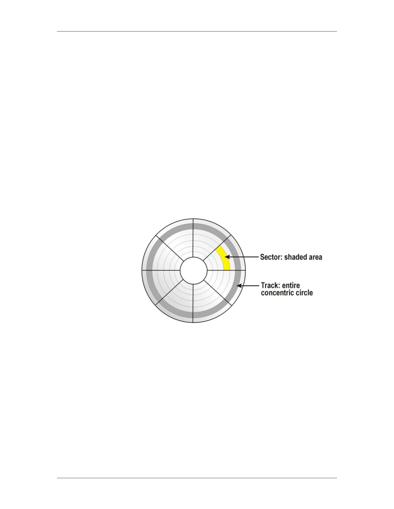
Hard drives are divided into tracks, sectors, heads, and cylinders.
Geometry
Each one is detailed here.
Most motherboard BIOS chips prior to 1997 do not automatically
detect geometry information. This information is usually annotated
on a sticker fixed to the drive. If not, check user reference manuals
for the manufacturer’s Web site for a listing of this information by
hard drive type. It is a good idea to record these values for future
reference.
In computer forensic investigations, it is important to know where
data is stored on a hard disk because you may be asked during trial
about the exact location of a hidden data file. For example, you
may be asked to identify the track, sector, and cylinder on which a
hidden file is located on a seized computer system.
Tracks
Tracks are the concentric circular paths that are placed on both
sides of the platter. Tracks are a specified area that the read/write
head hovers over. They are arranged starting at the center of the
platter working to the outer edge.
Tracks are measured in density called tracks per inch (TPI). The
first PC hard disks in 1982 had 200-300 TPI. Today, drives have
over 100,000 TPI. Tracks are uniform on every platter in the drive
and a cylinder is formed by alignment of the same tracks on all
platters.
01/09
For Official Use Only - Law Enforcement Sensitive
D-17
Network Intrusion Responder Program
Appendix D
Hard Drive Geometry, continued
Sectors
Sectors are shaped segments of tracks. Each sector holds 512 bytes
of data. With today’s technology, each track can have between 17
and 100 or more sectors.
Heads
Heads on the platter represent the side of the platter. These are
sometimes confused with the read/write heads, which are the
devices that relay data to and from the platters.
Cylinders
All platters in a stack are aligned with each other and they move in
unison. A cylinder is formed by identically positioned tracks on
every platter.
Clusters
A cluster is a group of one or more sectors that form the smallest
addressable area of storage on a disk. Although a cluster is the
smallest unit of disk space used by an operating system, cluster
sizes vary and depend upon the OS and the partition size of the
disk.
D-18
For Official Use Only - Law Enforcement Sensitive
01/09
Appendix D
Network Intrusion Responder Program
RAID
RAID
A Redundant Array of Independent Disks (RAID) is a method of
combining multiple hard drives and storing data in different
locations on those drives at the same time. Instead of writing data
to individual drives, such as drive C and drive D, a RAID allows
the OS and the user to view and use drives C and D as one logical
drive. Using multiple drives that appear as one logical drive
instead of using one large hard drive allows for greater
performance, capacity, and reliability.
There are two methods of writing to the RAID: striping and
mirroring. Various types of RAIDs are produced using different
combinations of striping, mirroring, error correction, and parity.
RAIDs are created using software or hardware methods. The most
common types of RAIDs include:
RAID 0
RAID 5
RAID 1
RAID 6
RAID 3
RAID 0+1
RAID 4
RAID 1+0
Striping
Striping involves partitioning each drive’s storage space into units
ranging from 512 bytes to several megabytes. Data is written in
bytes or groups of bytes across multiple drives as specified by the
interleave ratio. Since more then one drive is reading and writing
data at the same time, performance is greatly enhanced.
Mirroring
Disk mirroring is a technique that stores the same data on a pair of
disks. Mirroring ensures that you always have an exact duplicate
of the drive providing fault tolerance.
01/09
For Official Use Only - Law Enforcement Sensitive
D-19
Network Intrusion Responder Program
Appendix D
RAID, continued
Parity
Parity is a method of checking data when it is copied from one
storage place to another to ensure that the data has not been lost,
overwritten or corrupted. When a group of bits are copied, an
additional parity bit (binary digit) is added. This bit ensures that
the data has been copied successfully.
In RAID, parity is used for data recovery. It is implemented
through exclusive OR (XOR), a logical process that returns a value
of “1” if two data bits are not the same. If any two bits are the
same (both 1s or both 0s), the result is 0. If they are 1 and 0, the
result is a 1.
This XOR process is shown in the following table:
Data Bit A
Data Bit B
Output
0
0
0
0
1
1
1
0
1
1
1
0
You then compare each data bit in a data set to get the XOR result
or “parity data.” Here’s an example of how parity data is
calculated:
Data A =
10100101
Data B =
11110000
Parity Data = 01010101
Notice that each data bit is put through the XOR process, which is
shown in the table. The first digits of Data A and B are both 1s.
They are alike. Therefore, the result is a 0 for the first digit of the
XOR result. For the second digits, Data A and B do not have
similar binary numbers. The 0 and the 1 yield an XOR result of 1.
This process continues for each bit in a data set.
In this example, Data A, B, and the parity data are all on separate
drives in the RAID. If any one drive becomes missing or corrupt
due to failure, you can reconstruct the missing data using the
remaining two drives through the same XOR process.
D-20
For Official Use Only - Law Enforcement Sensitive
01/09
Appendix D
Network Intrusion Responder Program
RAID, continued
ECC
Error Correction Code or Error Checking and Correcting (ECC)
looks for errors in data that is being read or transmitted. Unlike
parity that resends faulty information, ECC attempts to correct the
information.
ECC uses a mathematical code to describe each 64-bit word and
sends that code with the data. When the data is about to be stored,
the code is regenerated. If there is a match, the data is saved. If the
codes are different, the original code is used to correct the bits.
Types of RAIDs
The various types of RAIDs work in different ways. Here are the
five most common types.
RAID 0
RAID 0 implements a striped disk array without any mirroring,
ECC, or parity. The data is simply placed across several drives
allowing each drive to read and write data at the same time. This
configuration provides the best efficiency and performance, but
provides no fault tolerance.
RAID 1
RAID 1, also known as disk mirroring, writes the same data to a
pair of hard drives. This implementation provides for the best fault
tolerance, but the most overhead.
RAID 3
RAID 3 implements striping small amounts of data across several
hard drives with one drive assigned to store parity information.
Some RAID controller card manufacturers do not support this type
of architecture because a RAID 5 with small stripes yields similar
results.
RAID 5
RAID 5 implements striping large amounts of data across several
hard drives while rotating parity throughout all the attached drives.
This array requires a minimum of three drives.
RAID 0+1
RAID 0+1 implements a mirrored array of RAID 0 drives. This
type offers excellent performance and fault tolerance. A minimum
of four drives is required.
01/09
For Official Use Only - Law Enforcement Sensitive
D-21
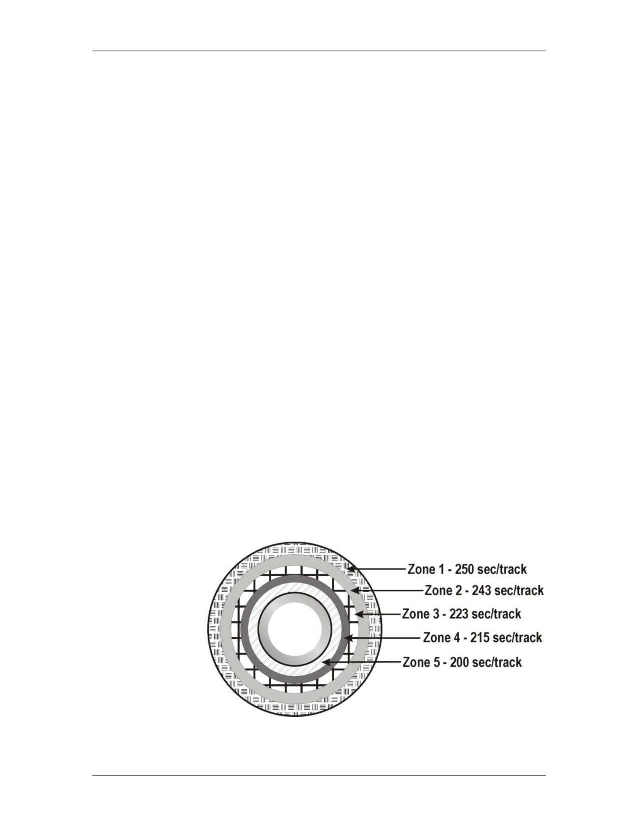
Network Intrusion Responder Program
Appendix D
Drive Preparation
Data Allocation
Along with all of the differences between drive controllers and
and Storage
disk connectors, there are also differences in the ways that data is
stored onto hard drives. As information is stored onto a hard drive
platter, it must be placed into an addressable location for later
recollection.
Logical Block
Logical block addressing (LBA) is a process that assigns linear
Addressing
numbers to all sectors in a drive. This process, now a standard,
extends the drive’s storage capacity from the normal 528 MB.
Older motherboard BIOS types or operating systems may require
LBA to be translated into CHS geometry. If required, this
translation is performed automatically. The 28-bit LBA supports a
partition as large as 137 gigabytes. The newer 48-bit LBA will
theoretically support a single drive with storage of 144 petabytes.
Zoned Bit
Zoned bit recording lessens wasted storage space on the outer
Recording
sections of the hard drive by reassigning the sectors on a disk
according to the physical size of the track. Data in small tracks
near the center of the disk is written closer together than data that
is in the larger outer tracks. Therefore, outermost tracks can
contain more sectors per track than the smaller inner tracks. The
drive controller can recognize the variable number of sectors per
track in different zones. Zoned bit recording is set during the low-
level format.
Hard Drive with Zoned Bit Recording
D-22
For Official Use Only - Law Enforcement Sensitive
01/09
Appendix D
Network Intrusion Responder Program
Drive Preparation, continued
Perpendicular
Perpendicular recording is a technology that increases the amount
Recording
of storage space on a hard drive. Using perpendicular recording,
manufacturers have produced micro-drives with over 100
gigabytes of storage on a 1.8” drive, a 320 gigabyte 2.5” laptop
drive, and a 3.5” drives with over 1 terabyte of storage. This
recording method can increase the storage density of a hard drive
by almost ten times compared to longitudinal recording.
Longitudinal recording, which has been used since the inception of
hard drives, stores bits side-by-side on a magnetic surface.
Traditionally, when manufacturers want to increase the amount of
storage space, they decrease the size of the magnetic particles on
the hard disk surface. This frees more storage space on the disk.
However, if the magnetic particles become too small, the data is
susceptible to corruption. The risk of data corruption limits the
amount of storage capacity with longitudinal recording.
Perpendicular recording vertically records the bits of a sector to a
hard drive. Stacking the bits vertically increases the amount of
storage density. With perpendicular recording, more data can be
stored with less risk of corruption.
01/09
For Official Use Only - Law Enforcement Sensitive
D-23
Network Intrusion Responder Program
Appendix D
Hard Drive Preparation
Hard Drive
A hard drive must be prepared before using it to store data. This
Formatting
preparation process involves two formatting steps (low-level
formatting and high-level formatting) with a partitioning step
between them. Here are the basic steps to prepare a hard drive:
Step 1: Low-level
The purpose of low-leveling formatting, also called physical
Formatting
formatting, is to set the drive geometry by first setting the tracks
and then dividing them into sectors.
Step 2:
To use a hard drive, it must be partitioned. To understand
Partitioning
partitioning, consider this analogy:
A farmer owns acres of fields. He can both plow and plant the
entire parcel at once or he can separate the land into smaller plots
and seed them independently at different times. The same is true
for a hard drive. You can partition all of the space as one large
parcel to hold all of your operating system and data. Or you can
partition the drive into smaller plots and use each one
independently. In fact, after each partition is formatted, it will
appear to the operating system as a separate drive.
When you purchase a computer, the original equipment
manufacturer (OEM) has partitioned the drive for you as a single
partition. This partition shows up on your system as the C: drive.
However, partitioning your drive into multiple drives offers many
benefits. For instance, you could place your operating system on
one partition and all of your data on another. If you need to
reinstall the operating system, you could do so without affecting
your data partition. In addition, you can format different partitions
with different file systems in order to install a different operating
system on the same physical drive.
There are many ways to partition a drive and the operating systems
provide the tools. MS-DOS uses the FDISK utility. Windows XP
uses Disk Management and some distributions of Linux use Disk
Druid. While the interfaces look different, the result is the same.
D-24
For Official Use Only - Law Enforcement Sensitive
01/09
Appendix D
Network Intrusion Responder Program
Hard Drive Preparation, continued
Step 2:
There are only two types of partitions: primary and extended. You
Partitioning,
need at least one primary partition to boot a computer from a hard
continued
drive. Extended partitions are typically used for storing data and
applications and cannot be used to boot a computer.
Hard drives can support up to four primary partitions or three
primary partitions and one extended partition. However, the
FDISK utility only recognizes one primary partition per physical
drive, so DOS and Windows 9x/ME can only have one primary
partition per drive. Linux, Unix, Windows 2000, XP and Vista can
all support four primary partitions.
Once a primary partition is created, it is ready for high-level
formatting. Extended partitions, however, require one additional
step. Before an extended partition can be formatted, it must be
further organized into logical drives. This can be accomplished
with the same partitioning utilities mentioned earlier. Once you
create the partitions and logical drives, you can proceed to the next
step - High-level Formatting.
Step 3: High-level
High-level formatting, also called logical formatting, is performed
Formatting
by the operating system. High-level formatting writes the
necessary operating system-dependant file structures to the drive
so that the drive can manage and store data. This includes
establishing the boot record, file allocation table, and the root
directory. The high-level formatting process also scans the disk for
areas that are unable to store data. These areas are marked as bad
sectors and are isolated.
MS-DOS
MS-DOS, Windows 9x, and Windows ME all make use of the
FAT
MS-DOS-based FDISK utility. FDISK is responsible for the
creation and deletion of partitions and logical drives. Once these
partitions are created, they cannot be altered easily. File Allocation
Table (FAT) partitions cannot be resized without the use of third-
party software. Rather, the original partition must be deleted and
then the new partitions can be created.
Warning: Any data residing on a partition will be destroyed as
soon as the partition is removed. Any data that is to be
saved from the partition must be backed up before
removing the partition.
01/09
For Official Use Only - Law Enforcement Sensitive
D-25
Network Intrusion Responder Program
Appendix D
Hard Drive Preparation, continued
FAT File System
Each partition or logical drive contains a FAT. The FAT manages
Characteristics
a list of where files begin and end on the particular drive. This list
is constantly being updated with new information as files are
saved, deleted, renamed or moved. It is critical that this list stay
up-to-date and intact to allow the operating system to access files.
It is considered so critical that the latest backup copy of the FAT is
saved in another area on the hard drive. This backup copy is used
to restore the original if it is damaged or altered.
FAT16 used a 16-bit length number to identify the various clusters
on a hard drive. This limited the addressable capacity of a hard
drive to 65,526 clusters, or 2 gigabytes of data. Those using
FAT16 on drives that were larger than 2 Gb were required to
partition the drive to fully use the drives capacity.
FAT32 uses a 32-bit length number to identify all of the clusters
on a hard drive. This increase allows the file system to address
approximately 268,400,000 clusters, or approximately 2 terabytes
of information.
D-26
For Official Use Only - Law Enforcement Sensitive
01/09
Appendix D
Network Intrusion Responder Program
Hard Drive Preparation, continued
FAT Drive
FAT 16/32 systems can support up to two partition types per hard
Identification
drive. Those types are primary and extended. The extended
partition contains logical drives.
Each primary partition and each logical drive within an extended
partition is assigned a drive letter starting with C. There is a unique
aspect to drive letter assignment in a FAT 16/32 environment.
When assigning drive letters, primary partitions take precedence
over logical drives.
For example, consider the following configuration that begins with
one hard drive that has been partitioned into one primary partition
and one extended partition with two logical drives.
Drive 1
Primary
Extended
Drive C
Drive D
Drive E
Assume that another hard drive (Drive 2) is added to the system
and contains one primary partition. How would this addition affect
the current configuration?
Drive 1
Drive 2
Primary
Extended
Primary
Drive C
Drive E
Drive F
Drive D
Note that the new drive’s primary partition was assigned the drive
letter “D,” not “F.”
01/09
For Official Use Only - Law Enforcement Sensitive
D-27
Network Intrusion Responder Program
Appendix D
Hard Drive Preparation, continued
NTFS
Windows 2000 and Windows XP can operate in a FAT32 or
FAT16 environment, but most users opt for the default file system,
NTFS (New Technology File System). In Windows Vista, NTFS is
required to install the operating system. NTFS is more stable than
the FAT system and offers such benefits as file compression and
data encryption. These options are not readily available on a FAT-
based system. In addition, MS Windows 2000, Windows 2003,
Windows XP Professional, and Windows Vista support dynamic
volumes, which allow partitions to be added or extended without
resulting in data loss.
NTFS Partitioning
Unlike the DOS method described previously, partitioning is not
and Formatting
performed at the command prompt level. FDISK neither supports
nor offers NTFS as a partitioning option. The process of
partitioning the primary partition occurs during the installation
process. This begs the question, “What if I want to add an
additional hard drive to my system; how can I partition and format
it with NTFS?”
The Windows Disk Management tool allows you to add, delete or
modify partitions. In addition, it can be used to display general
volume information including: file system type, the amount of
available space and the drives total capacity. It can also be used to
convert a partition from FAT16/32 to NTFS.
There are a number of ways that a partition can be formatted or
reformatted to the NTFS file system. The Disk Administrator,
described previously, can be used to format the partition. In
addition, the partition can be formatted via My Computer. The
new partition(s) display when the My Computer folder is opened.
Right clicking on the partition will result in a context-sensitive
menu with Format as an option. Lastly, the Format command can
be executed via the command line. The command “format [drive
letter] /fs:ntfs” will format an existing partition to the NTFS
standard.
D-28
For Official Use Only - Law Enforcement Sensitive
01/09
Appendix D
Network Intrusion Responder Program
Hard Drive Preparation, continued
NTFS Partitioning
The following command example will convert the D: drive to
and Formatting,
NTFS.
continued
convert D: /fs:ntfs
A reboot will be required if the desired partition is the system
drive, most commonly the C: drive. Once the command is
executed, the user will be prompted with a Yes/No question asking
if he or she wishes to convert the specified drive to NTFS on next
reboot. Selecting Yes will schedule the conversion to happen
during the next reboot sequence.
Note: FAT partitions can be converted to NTFS while preserving
the data; however, NTFS partitions cannot be converted to
either of the FAT file systems.
NTFS File System NTFS utilizes the MFT (Master File Table) to track files and their
Characteristics
associated locations on a particular volume. The MFT is similar to
FAT in that it maps the location of directories and folders and is
updated whenever a file is accessed, changed, deleted or added to
the volume.
There are, however, significant differences. The File Allocation
Table can be thought of as a static fixed-sized chart that cannot
change in size. However, the MFT is much more dynamic than the
FAT. The MFT is a relational database that can grow in size if
necessary. The MFT is created when the drive (or volume) is
formatted for the NTFS specifications.
Since the MFT has the capability of growing, a certain amount of
contiguous space is reserved for MFT expansion. This area is
sometimes called the “MFT Zone.” Initially, this zone is
approximately 12 percent of the total volume capacity; however,
the MFT can grow past that size if needed. Most NTFS volumes
are no larger than 2 terabytes in size. However, the dynamic nature
of the MFT allows an NTFS volume to reach 16 exabytes, which is
equivalent to approximately 16,000,000 terabytes in capacity!
01/09
For Official Use Only - Law Enforcement Sensitive
D-29
Network Intrusion Responder Program
Appendix D
Hard Drive Preparation, continued
NTFS Drive
Assigning drive letters in NTFS is somewhat different than in the
Identification
FAT file system. Drive letters are assigned as they are discovered
by the operating system. Drive letters do not change when devices
are added or removed from a system.
In the following example, consider a system that consists of a hard
drive with one primary partition and one logical partition.
Hard Drive 1
Primary Partition
Logical Partition
C:
D:
Assume that a second hard drive is added to this system. This hard
drive consists of a primary partition and a logical drive. The
following table depicts the results of adding the new drive.
Hard Drive 1
Hard Drive 2
Primary
Logical
Primary
Logical
C:
D:
E:
F:
Notice that the new primary partition (E:) was not assigned the
drive letter D: as it would in a FAT file system.
Linux
Linux offers you the opportunity to partition a hard drive during
the installation of the operating system, much like NTFS-based
operating systems. Fedora, a Linux distribution based off the
former Red Hat Linux, uses the Disk Druid utility to offer a
graphical, mouse driven menu system that creates the partitions
based on the installer’s preferences.
In addition, Linux offers an FDISK program that is very similar to
the DOS-based utility. It can be used to create and remove various
partitions as well as view the status of a hard drive’s configuration.
A partition within Linux can be formatted to a number of file
systems, including:
Second Extended File System (ext2)
Third Extended File System (ext3)
Reiser File System
D-30
For Official Use Only - Law Enforcement Sensitive
01/09
Appendix D
Network Intrusion Responder Program
Hard Drive Preparation, continued
File System
The ext2 file system offered more features than Linux’s earliest
Characteristics:
file systems. These features included better space allocation, larger
Ext2
partition sizes (up to 16 terabytes in size), and support of long file
names. Most notable, ext2 was configurable. Like most aspects of
Linux, the file system could be modified to fit the needs of the end
user. Ext2 was introduced in 1993 and became the standard file
systems for many different versions of Linux.
Ext3
Since 2001, most Linux distributions began to use ext3 as the
default file system. In comparison to ext2, ext3 provides greater
reliability by taking advantage of journaling, which offers a more
reliable file recovery process than ext2.
Journaling is a feature of a file system that keeps track of all items
related to the main data areas of the disk. For example, when
saving changes to a file, the system will inform the journal that it
is about to make certain changes to a file. Once the change has
been implemented, the journal entry is either marked as completed
or is removed all together.
The benefit of journaling is that it can recreate anything that was
lost or corrupted due to a problem or failure. For example, if a
power outage occurs while you are saving a file, the journal may
be referenced to complete the change after power is restored. At
the very least, the original file will not be corrupted and it will be
returned to its original state.
If the same scenario occurred on an ext2 system, some of the
cached data may not have been written to the disk, and the file
would become corrupt. After an unclean shutdown, each volume
must be checked for consistency before it can be mounted on an
ext2 file system.
Ext3 systems do not require a file system check after an unclean
shutdown. System checks occur only in extreme circumstances
such as hardware failures. Recovering from a power failure takes
much less time when using an ext3 file system rather than the ext2.
Ext3 also boasts a faster read/write speed than ext2. This is
because ext3 uses the journal to not only protect files, but also to
optimize the hard drive’s read/write head motions. As a result, the
read/write process is completed in a more efficient manner.
01/09
For Official Use Only - Law Enforcement Sensitive
D-31