ORGANIZATIONAL MAINTENANCE MANUAL WITH REPAIR PARTS LIST FOR RIFLE, 7.62 MM, AK-47 (2009) - page 3

INTENTIONALLY BLANK

TM 8370-50007-OR/1
0004 00
DESCRIPTION AND USE OF OPERATOR CONTROLS AND INDICATORS
GENERAL
This section describes the various controls for the proper operation of the 7.62 mm AK-47 rifle, and accessories.
OPERATOR CONTROLS AND INDICATORS
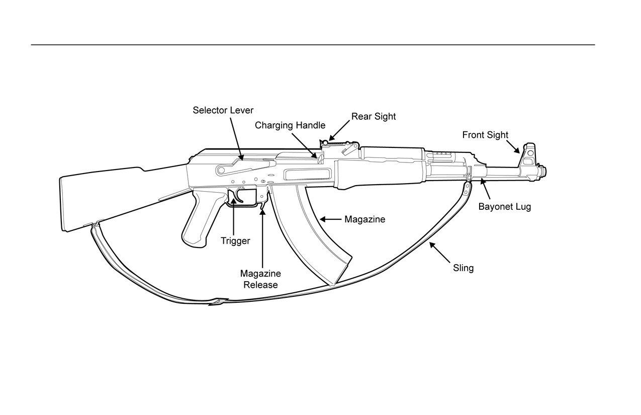
1. Right Side View. Refer to Figure 1.
a. Front Sight. Allows the operator to adjust the windage and elevation of the strike of the round.
b. Bayonet Lug. Allows for attachment of a bayonet.
c. Rear Sight. Contains the rear sight aperture on the end of the sight leaf. The slider on the sight leaf to allow the
operator to adjust for target distance.
d. Charging Handle. Is part of the bolt carrier and allows the operator to chamber a round and cock the weapon.
e. Magazine. Contains up to 30 rounds of 7.62 x 39 mm ammunition.
f.
Magazine Release. Allows the operator to release the magazine to remove it from the weapon.
g. Selector Lever. Allows the operator to select the mode of fire and place the weapon on SAFE.
0004 00-1
TM 8370-50007-OR/1
0004 00
h. Trigger. Fires the weapon when pulled.
i.
Sling. Provides the operator a means of carrying the weapon
Figure 1. Right Side View of the Weapon.
0004 00-2
TM 8370-50007-OR/1
0004 00
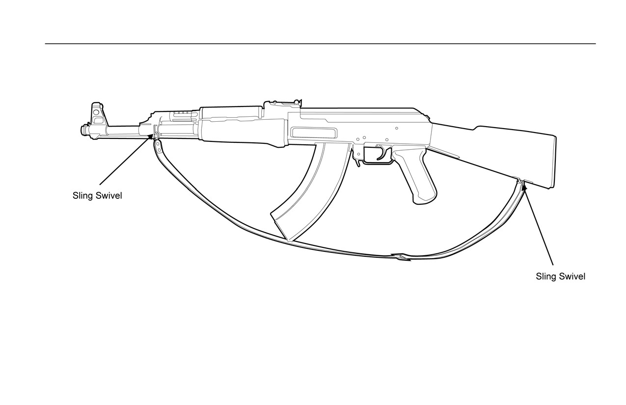
2. Sling Swivels. The sling swivels allow the operator to attach a sling to the weapon. Refer to Figure 2.
Figure 2. The Sling Swivels.
0004 00-3
TM 8370-50007-OR/1
0004 00
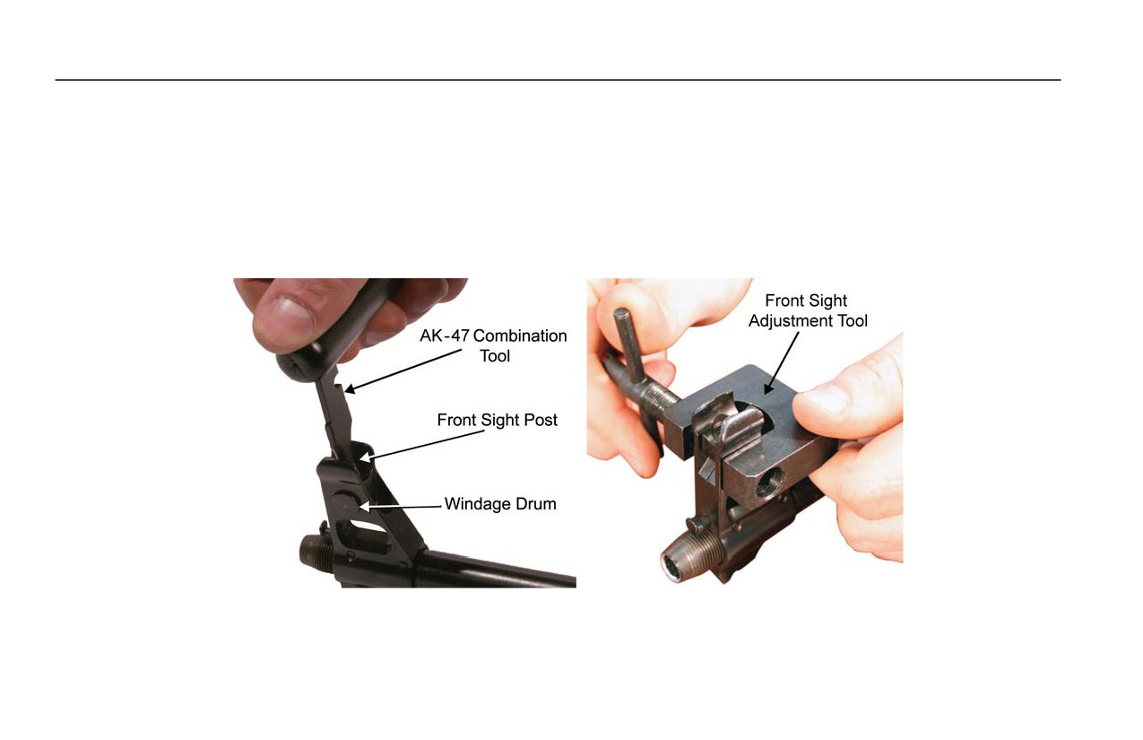
3. Front Sight. Refer to Figure 3.
a. Front Sight Post. The front sight post is screwed up or down when zeroing the rear sight. The AK-47 combination
tool (or the AK-47 front sight adjustment tool) is used to adjust the front sight.
b. The Windage Drum. The windage drum is moved left or right to adjust for windage. An AK-47 front sight
adjustment tool (or an M249 front sight adjustment tool) is used to adjust the windage drum.
Figure 3. Using the Front Sight and the AK-47 Front Sight Adjustment Tool.
0004 00-4
TM 8370-50007-OR/1
0004 00
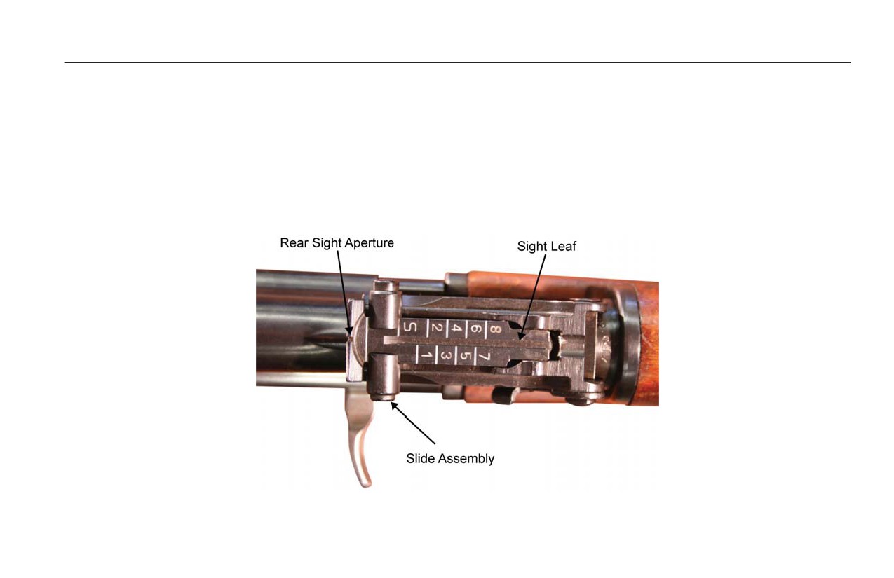
4. Rear Sight. Refer to Figure 4.
a. Rear Sight Aperture. The rear sight aperture is on the end of the sight leaf.
b. Sight Leaf. The sight leaf has distance markings for up to 800 meters.
c. Slide Assembly. To adjust for distance to target, move the slide assembly to the proper distance marking on the
sight leaf (e.g. “S” for less than 100 meters, “1” for 100 meters, and “2” for 200 meters).
Figure 4. The Rear Sight with the Slide Assembly set on “S”.
0004 00-5
TM 8370-50007-OR/1
0004 00
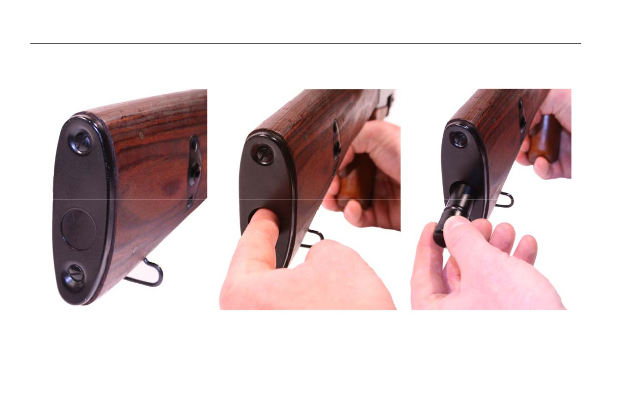
5. Buttstock Assembly. AK-47 models with wooden buttstocks have a storage area for the AK-47 combination tool kit
inside the buttstock that is accessible through a trapdoor in the buttplate. Refer to Figure 5.
Figure 5. Accessing the AK-47 Combination Tool Kit.
0004 00-6
TM 8370-50007-OR/1
0004 00
6.
Selector Lever.
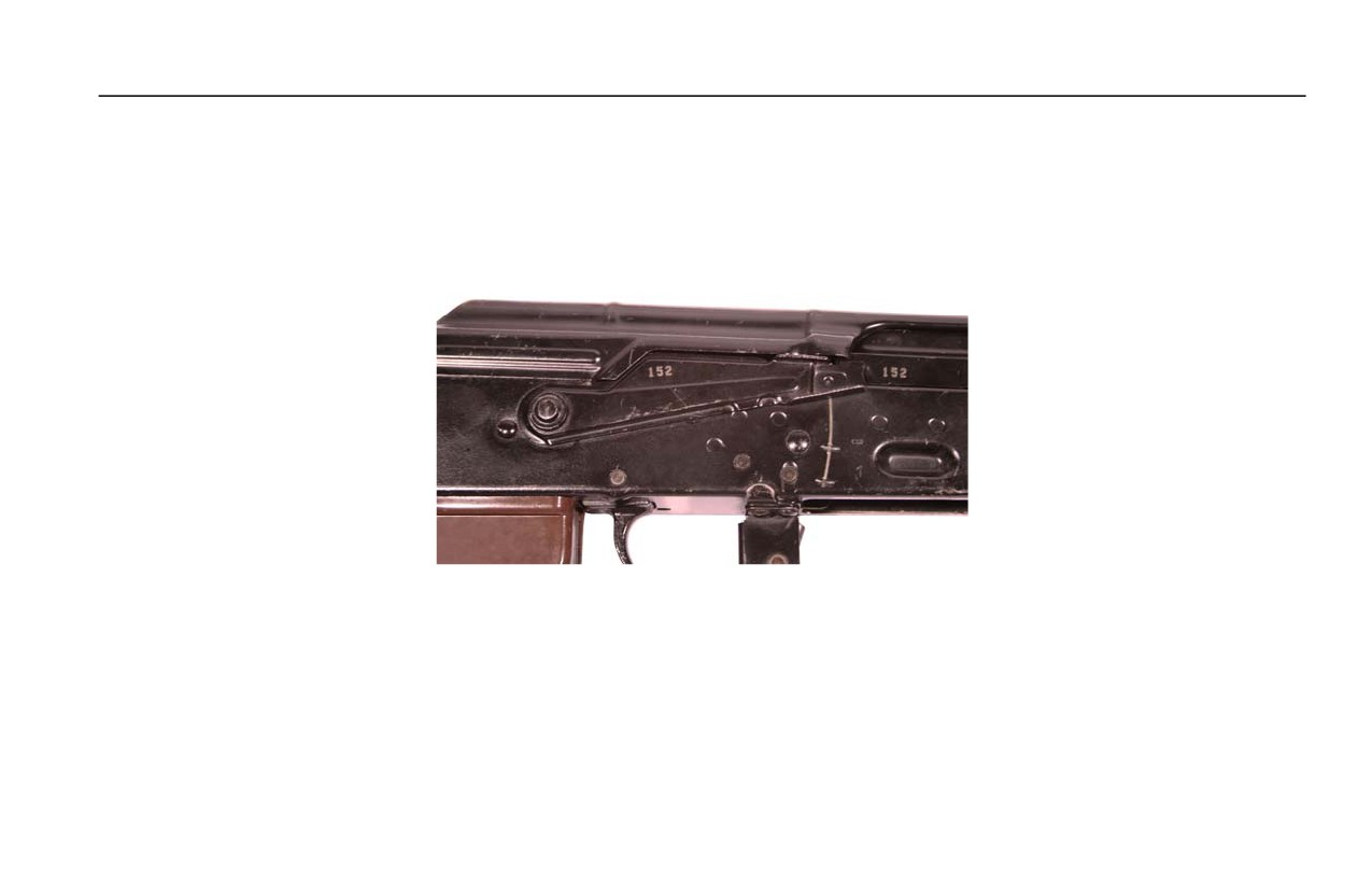
a. SAFE. The weapon will not fire when the selector lever is set on SAFE. The selector lever must be off SAFE to
chamber a round or to clear the weapon. Always place the selector lever on SAFE when inserting and removing a
magazine. The selector lever can be set on SAFE even when the hammer is forward. Refer to Figure 6.
Figure 6. Selector Lever Placed on SAFE.
0004 00-7
TM 8370-50007-OR/1
0004 00
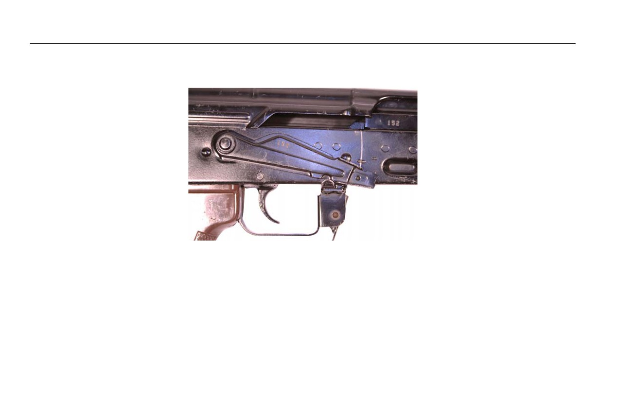
b. SEMI. When the selector lever is placed on SEMI, the weapon will fire one round each time the trigger is pulled.
The selector lever must be set on SEMI or AUTO to chamber a round or to clear the weapon. Refer to Figure 7.
Figure 7. The Selector Lever Placed on SEMI.
0004 00-8
TM 8370-50007-OR/1
0004 00
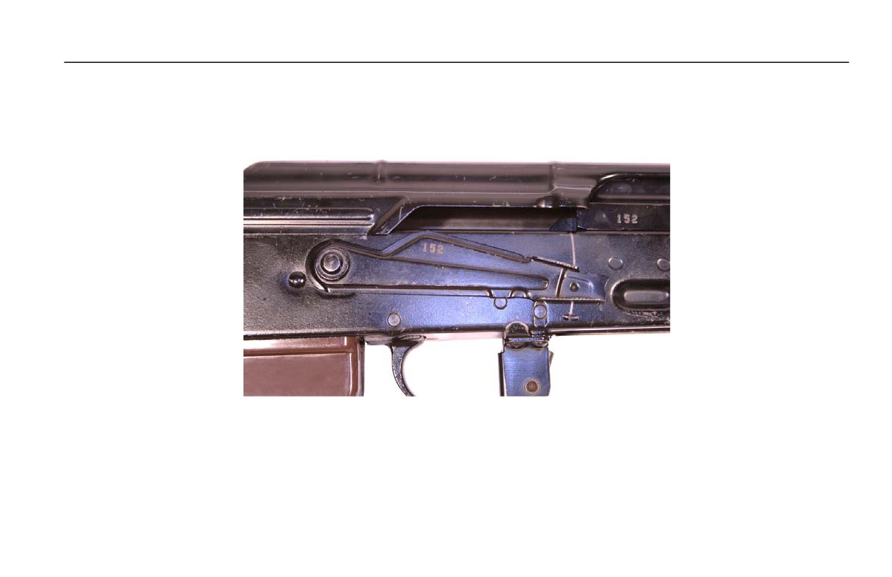
c. AUTO. When the selector lever is placed on AUTO, the weapon will continue to fire as long as the trigger is held
to the rear or until the magazine is empty. The selector lever must be set on SEMI or AUTO to chamber a round
or to clear the weapon. Refer to in Figure 8.
Figure 8. The Selector Lever Placed on AUTO.
END OF WORK PACKAGE
0004 00-9/10 blank

INTENTIONALLY BLANK

TM 8370-50007-OR/1
0005 00
OPERATION UNDER USUAL CONDITIONS
GENERAL
This section contains instructions for the operation of the 7.62 mm, AK-47 rifle under conditions of moderate temperature
and humidity.
PREPARATION FOR FIRING
WARNING
Check the bore to ensure it is clean and free of obstruction. Failure to follow this warning
may result in injury or death to personnel. Do not use the cap of the combination tool kit
as a blank firing device.
1. Ensure the weapon is properly lubricated.
2. Check the weapon for correct assembly and proper operation.
3. Check the ammunition for grade, identification markings, and serviceability.
4. Operate and inspect the controls for satisfactory functionality.
PLASTIC MAGAZINE
In addition to metal AK-47 magazines there are plastic AK-47 magazines, which are lighter and more water resistant.
0005 00-1

TM 8370-50007-OR/1
0005 00
LOADING A MAGAZINE
CAUTION
Ensure ammunition is free of sand, mud, moisture, frost, snow, ice, grease, or other
foreign debris. Also, check the ammunitionfor dents in cartridges or bad primers.
To load ammunition into a magazine, follow these instructions:
1. Hold the magazine with the one hand, with the follower facing up.
2. With the opposite hand, insert the rounds into the feed mechanism of the magazine.
3. Ensure the rounds are seated against the rear of the magazine.
LOADING THE WEAPON
WARNING
If the weapon is dropped or jarred with a loaded magazine in place, it could chamber a
round and subsequently cause a negligent discharge. Failure to follow this warning may
result in injury or death to personnel.
CAUTION
NEVER ride the charging handle forward. Allow it to move forward on its own.
1. Set the selector lever on SAFE.
0005 00-2
TM 8370-50007-OR/1
0005 00
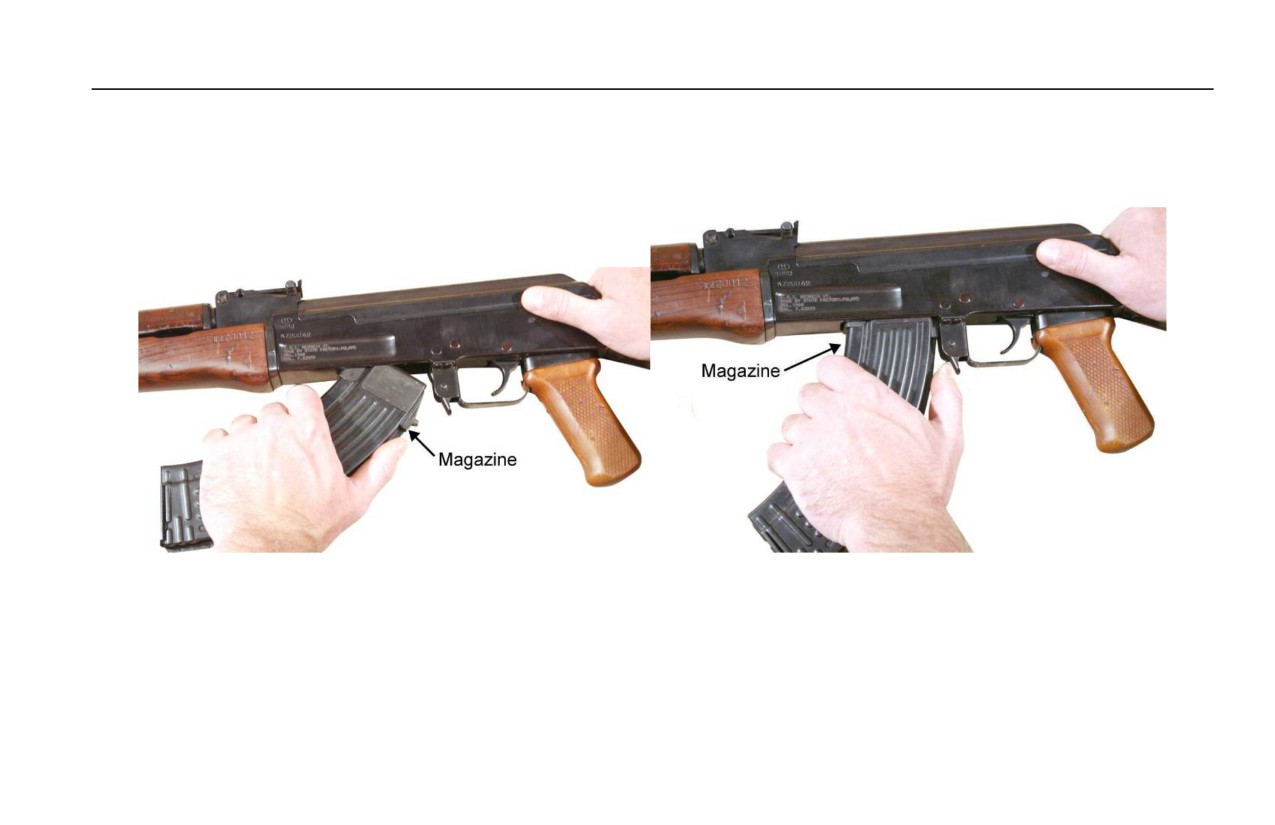
2. Seat the front lip of the magazine against the front of the magazine well and rock the magazine up and to the rear,
until an audible “click” is heard indicating that the magazine release has locked the magazine in place. Push up and
pull down on the magazine to ensure that it is firmly seated. Refer to Figure 1.
Figure 1. Inserting a Magazine.
3. Place the selector lever on SEMI.
4. Charge the weapon to chamber the first round. DO NOT ride the charging handle forward.
5. Place the selector lever on SAFE.
0005 00-3
TM 8370-50007-OR/1
0005 00
UNLOADING AND CLEARING THE WEAPON
1. Point the weapon in a safe direction and set the selector lever on SAFE.
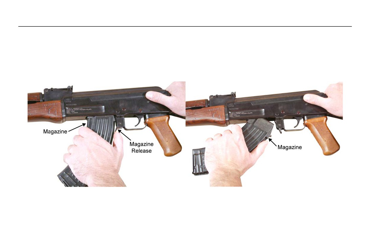
2. To remove the magazine, press the magazine release toward the magazine and rock the magazine down and forward.
Refer to Figure 2.
Figure 2. Removing the Magazine.
0005 00-4
TM 8370-50007-OR/1
0005 00
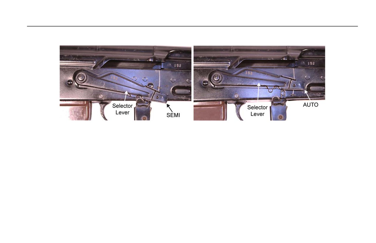
6. Place the selector lever on SEMI or AUTO. Refer to Figure 3.
Figure 3. Selector Lever on SEMI (left) or AUTO (right).
7. Pull and hold the charging handle to the rear.
8. Visually and physically inspect the chamber and receiver to ensure they contain no ammunition.
9. Release the charging handle, allowing it to return forward. Set the selector weapon on SAFE.
10. The weapon is now cleared and SAFE.
0005 00-5

TM 8370-50007-OR/1
0005 00
SETTING THE SIGHTS AND FIELD FIRING TECHNIQUES
NOTES
Detailed zeroing procedures will be covered in a separate period of instruction. This
section will describe how to set the front and rear sight to adjust the strike of the round
The front sight post and windage drum are used to zero the rear sight. The rear sight
assembly is used to adjust for distance to target during field fire.
A rule of thumb for adjusting the front sight post and the windage drum is to move the
post or drum in the OPPOSITE direction of the desired adjustment of the strike of the
round.
0005 00-6
TM 8370-50007-OR/1
0005 00
1. Front Sight.
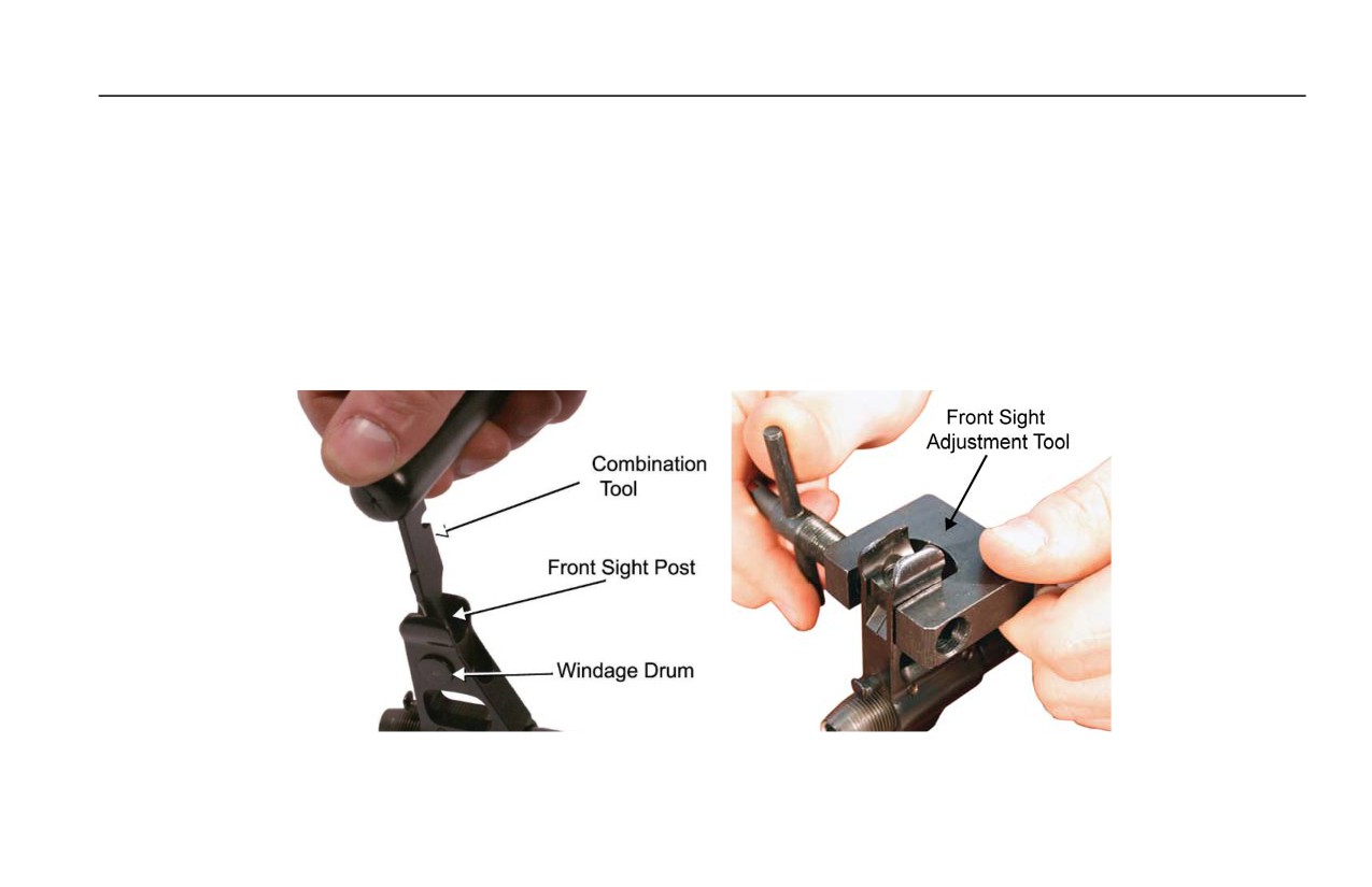
a. Front Sight Post. Screwing the front sight post down will move the strike of the round UP, screwing the front
sight post up will move the strike of the round DOWN. The combination tool (or the handle of the front sight
adjustment tool) is used to screw the front sight post down or up. Refer to Figure 4.
b. The Windage Drum. Pushing the windage drum left will move the strike of the round RIGHT, pushing it right
will move the strike of the round LEFT. The front sight adjustment tool (or an M249 front sight adjustment tool)
is used to move the windage drum. Refer to Figure 4.
Figure 4. Setting the Front Sight Post and the Windage Drum.
0005 00-7
TM 8370-50007-OR/1
0005 00
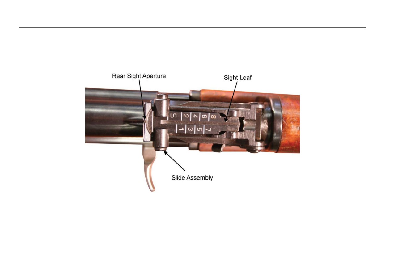
2. Rear Sight. The rear sight aperture is on the end of the sight leaf. Moving the slide assembly to different distance
markings on the sight leaf adjusts for distance to target. The slide assembly snaps into place on the distance markings
on the sight leaf. Set the slide on “S” for ranges under 100 meters, “1” for 100 meters, “2” for 200 meters. Refer to
Figure 5.
Figure 5. The Rear Sight with the Slide Assembly Set on the “S” Setting.
0005 00-8
TM 8370-50007-OR/1
0005 00
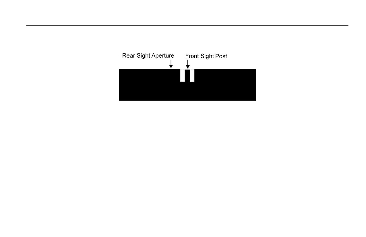
3. Aiming. Obtain a good sight picture and good sight alignment with the front sight post centered in the rear sight
aperture.
Figure 6. The Front Sight Post Centered in the Rear Sight Aperture.
4. Firing. Squeeze the trigger and fire.
FAILURE TO FIRE
WARNINGS
If a noticeable difference in sound or recoil of the weapon is experienced, stop firing.
Either condition could indicate an incomplete powder burn or a projectile lodged in the
bore.
0005 00-9

TM 8370-50007-OR/1
0005 00
WARNINGS - CONTINUED
If the weapon stops firing with a live round in the chamber of a hot barrel, remove the
round immediately. If the round cannot be removed within 10 seconds, wait 15 minutes
with the weapon pointed in a safe direction. This will avoid possible injury to personnel
from the cook-off of the chambered round. Keep the face away from the ejection port
while clearing a hot chamber. Failure to follow these warnings may result in injury or
death to personnel.
If the weapon stops firing, seek cover and perform the following actions:
1. Immediate Action. Follow the acronym SPORTS:
a. Slap upward on the magazine to ensure it is properly seated.
b. Pull and hold the charging handle to the rear.
c. Observe the chamber for rounds and debris.
d. Release the charging handle to strip a round from the magazine.
e. Tap the charging handle forward to ensure the bolt is fully seated.
f.
Shoot the weapon.
0005 00-10

TM 8370-50007-OR/1
0005 00
2. Notify the Unit Armorer. If immediate action (step 1) has been applied and the weapon fails to fire, notify the unit
armorer when the situation permits.
3. Remedial Action.
WARNING
If the weapon stops firing with a live round in the chamber of a hot barrel, remove the
round immediately. If the round cannot be removed within 10 seconds, wait 15 minutes
with the weapon pointed in a safe direction. This will avoid possible injury to personnel
from cook-off of the chambered round. Keep the operator’s face away from the ejection
port while clearing a hot chamber. Failure to follow these warnings may result in injury
or death to personnel.
Use the following steps to clear a cartridge case stuck in the chamber.
a. Remove the magazine. Refer to Unloading and Clearing the Weapon in this work package.
b. Pull the charging handle and hold it to the rear.
0005 00-11
TM 8370-50007-OR/1
0005 00
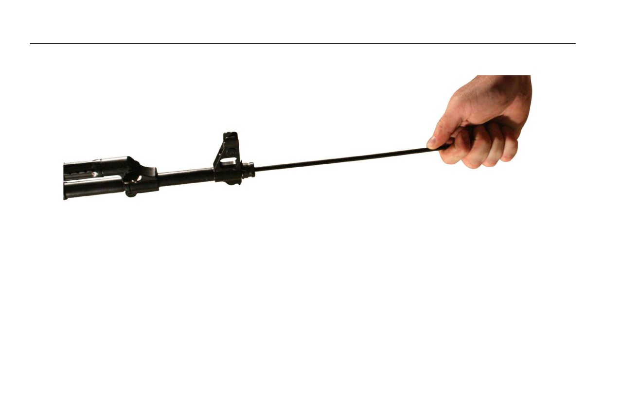
c. Insert the cleaning rod into the barrel from the muzzle end and tap out the cartridge case. Refer to Figure 7.
Figure 7. Cleaning Rod Inserted into the Muzzle.
0005 00-12

TM 8370-50007-OR/1
0005 00
4. Projectile Lodged in the Barrel.
WARNING
Immediately cease fire if an audible popping sound or reduced recoil is experienced
during firing. DO NOT apply immediate action. DO NOT attempt to remove a projectile
that is lodged in the barrel. Notify the unit armorer. Failure to follow these warnings may
result in injury or death to personnel.
Use the following steps if projectile is lodged in the barrel:
a. Retract the bolt slowly and remove the spent cartridge case.
b. Clear the weapon and check for unburned powder grains in the receiver or the bore. Check for a projectile lodged
in the bore.
c. Remove unburned powder from the bore before resuming fire.
d. If a projectile is lodged in the bore, notify the unit armorer.
AMMUNITION
Only approved 7.62 mm ammunition should be used in the AK-47 rifle.
0005 00-13

TM 8370-50007-OR/1
0005 00
USING TRACER AMMUNITION
Use tracer ammunition to help hit targets during hours of darkness or low light levels. Tracer ammunition is not as
effective as ball ammunition against most targets. When available, mix tracer ammunition with ball ammunition in the
magazine.
CHANGING MAGAZINES
In combat, insert a fully loaded magazine before the one being used is completely empty (if possible).
CARE, HANDLING, AND PRESERVATION
1. Packing. Ammunition is packed to withstand conditions ordinarily encountered in the field. Care must be exercised to
keep packing from becoming broken or otherwise damaged. All broken packing must be repaired immediately and all
markings must be transferred to replacement parts. Ammunition may be packed in metal-lined wooden boxes or metal
boxes. Damaged boxes containing metal liners should be air-tested and sealed if equipment to perform this work is
available.
WARNING
Store ammunition under protective cover and away from excessive heat and extreme
temperatures. Failure to follow this warning may result in injury or death to personnel.
2. Storing in the Open. When it is necessary to leave ammunition in the open, raise it at least 6 inches from the ground
and cover it with tarpaulins. Whenever possible, use wood between each row to permit full air circulation. Dig
suitable trenches to prevent water from running under the stack. Arrange tarpaulins to permit air circulation through
the stack, keeping the tarps at least 6 inches from the top, ends, and sides of the stack.
0005 00-14

TM 8370-50007-OR/1
0005 00
3. Moisture and High Temperature.
a. Keep boxes closed until the ammunition is needed. Ammunition removed from airtight containers, particularly in
damp climates, can corrode and become unserviceable.
b. Protect the ammunition from high temperatures and prolonged exposure to direct sun rays. Such exposure is likely
to affect the ballistic performance of the cartridges. The combination of high temperature and humidity can
destabilize propellant and the tracer mixture in tracer ammunition.
WARNING
DO NOT attempt to disassemble a cartridge or any of its components. DO NOT polish
brass components of cartridges. Failure to follow this warning may result in injury or
death to personnel.
CAUTION
The use of oil or grease on cartridges is prohibited.
0005 00-15

TM 8370-50007-OR/1
0005 00
4. General Care.
a. Protect the ammunition from sand, mud, moisture, frost, snow, ice, grease, and other foreign matter. Immediately
wipe off wet or dirty ammunition with a clean, dry cloth. If corrosion forms on cartridges, wipe it off with a clean,
dry cloth.
b. Brass cartridge cases are easily dented. Protect them from damage.
c. Protect a partially used box of ammunition from unauthorized use by firmly fastening the box cover in place.
PREPARATION FOR FIRING
After removing all packing materials, cartridges for the AK-47 are ready for use. Return unfired cartridges to their
original packing or pack them in suitable boxes. Use these cartridges first in subsequent firings in order to reduce stocks
of opened containers. Mark packing containers with the cartridge nomenclature, the quality of the cartridges, and the
ammunition lot number.
PRECAUTIONS IN FIRING
WARNINGS
Use only authorized ammunition manufactured to U.S. or NATO specifications.
DO NOT fire seriously corroded ammunition, dented cartridges, cartridges with loose
projectiles, cartridges exposed to extreme heat (135°F or more) until they are cooled, or
0005 00-16
TM 8370-50007-OR/1
0005 00
cartridges with loose projectiles are pushed in (short rounds). Failure to follow these
warnings may result in injury or death to personnel.
SLING
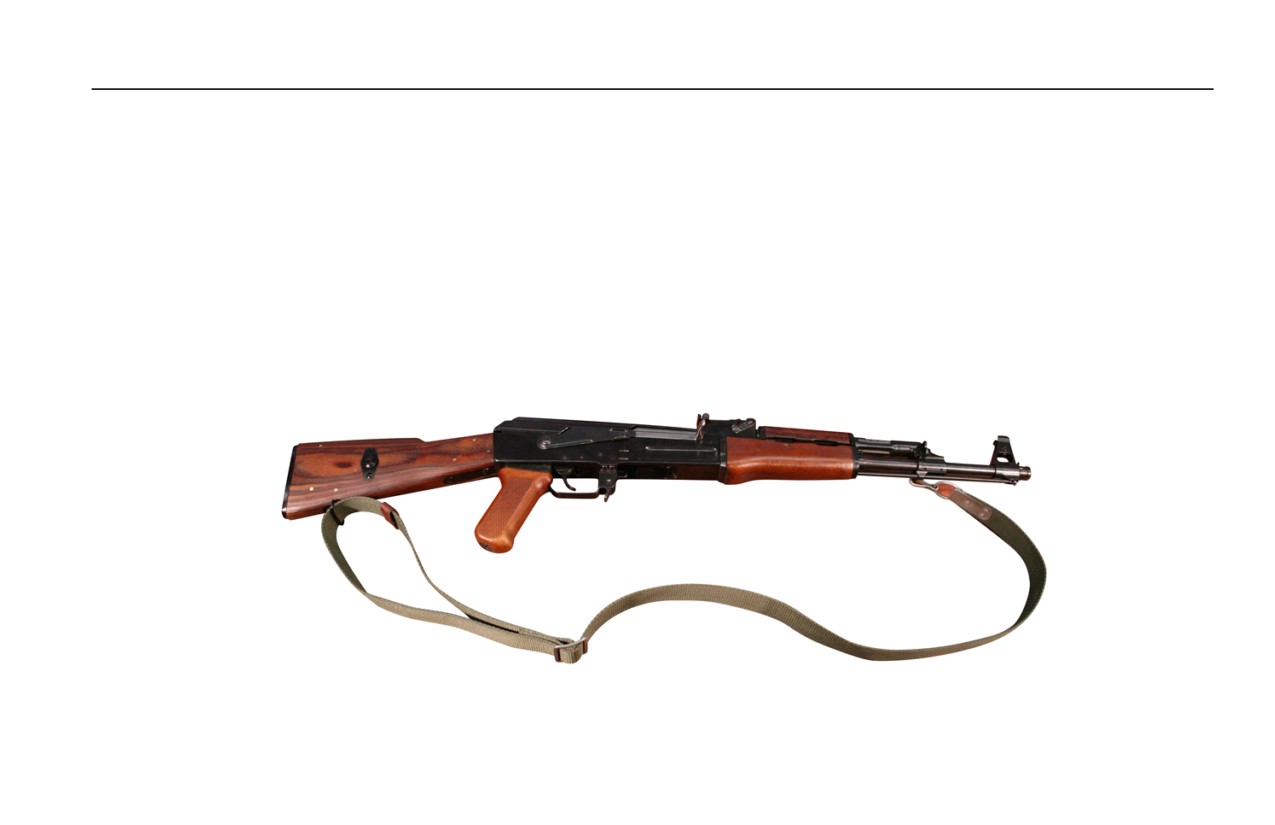
1. The sling is affixed to the weapon by first unlooping the sling from its buckle, then threading it through the rear sling
swivel on the buttstock.
2. Rethread the sling through its buckle.
3. Snap the sling hook onto the front sling swivel, located on the left side of the gas block. Refer to Figure 8.
Figure 8. Sling Attached to the Weapon.
0005 00-17
TM 8370-50007-OR/1
0005 00
4. Adjust the sling for fit using the sling buckle.
BAYONET
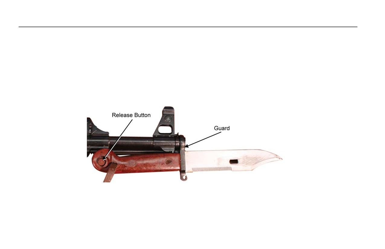
1. To install the bayonet, slide the guard over the thread protector and slide the butt of the bayonet over the bayonet lug
until the bayonet snaps into place on the lug. Ensure the bayonet is secure. Refer to Figure 9.
2. To remove the bayonet from the weapon, press the release button on the butt of the bayonet and slide the bayonet
away from the bayonet lug and off the thread protector. Refer to Figure 9.
Figure 9. Bayonet Attached to the Weapon.
END OF WORK PACKAGE
0005 00-18

TM 8370-50007-OR/1
0006 00
OPERATION UNDER UNUSUAL CONDITIONS
OPERATION UNDER UNUSUAL CONDITIONS
1. Extreme Cold Climate - Arctic.
a. Use lubricating oil, arctic, weapons (LAW) to clean and lubricate the weapon daily. Apply a light coat of LAW to
all functional parts. Do not use cleaner, lubricant, and preservative (CLP).
b. Cleaning and lubrication should be done inside a warm room. The weapon should be at room temperature if
possible.
c. To prevent condensation and freezing, allow gradual cooling by keeping the weapon covered when moving from
a warm area to a cold area.
d. Always attempt to keep the weapon dry. Do not lay a warm weapon directly in snow or ice.
e. Unload and hand function the weapon every 30 minutes to prevent freezing of functional parts.
f.
When moving a cold weapon into a warm area, condensation will form in and on the weapon. If possible, leave
the weapon in a protected, cold area outside. When the weapon is brought into a warm area, as it reaches room
temperature, it should be disassembled and wiped dry several times.
g. Ensure the insides of the magazines and ammunition are wiped dry. Moisture can freeze and cause malfunctions.
Do not lubricate ammunition.
0006 00-1

TM 8370-50007-OR/1
0006 00
h. The use of a muzzle cap, a protective magazine bag, and an overall weapon cover will help protect the weapon.
Use the items whenever the tactical situation permits.
i.
Check the bore for snow or ice obstructions before firing the first shot.
2. Hot, Humid Climate - Jungle.
a. Use CLP to clean and lubricate the weapon daily. Inspect hidden surfaces of the bolt carrier assembly, bolt
assembly, and receiver for corrosion. Pay close attention to all spring-loaded detents on the weapon.
b. To help prevent corrosion, remove hand prints with a dry wiping rag. Lubricate lightly with CLP.
c. Unload and check the insides of magazines frequently for corrosion and moisture. Wipe ammunition dry before
reloading.
d. Use a magazine bag and muzzle cap for protection when the tactical situation permits.
e. Protect the weapon from rain whenever possible.
3. Hot, Dry Climate - Desert.
a. Use CLP to clean and lubricate the weapon daily. Use a smaller than normal amount of CLP for cleaning.
b. Dust and sand will get into the weapon and magazines causing malfunctions. Perform a thorough cleaning of the
weapon daily and after all firing missions.
0006 00-2

TM 8370-50007-OR/1
0006 00
c. Corrosion is less likely to form on metal parts in a dry climate. Therefore, lubrication should only be applied to
internal working surfaces and functioning parts. Use normal amounts of CLP for internal lubrication. Unload
magazine and dry the inside of magazines daily. Wipe down ammunition daily. DO NOT lubricate magazines.
d. Use an overall weapon protection cover, muzzle cap, and spare magazine bags when the tactical situation permits
to keep blowing sand and debris out of the weapon and magazines.
4. Heavy Rain and Fording Operations - All Climates.
a. Perform maintenance in accordance with climate conditions.
WARNING
DO NOT fire the weapon if water is present in the barrel. Failure to follow this warning
may result in injury or death to personnel.
b. Always attempt to keep weapon dry. Always drain any water from the barrel prior to firing. Dry the bore with a
clean swab.
5. Nuclear, Biological, and Chemical (NBC). General procedures can be found in Marine Corps Warfighting
Publication: MCWP 3-37.2A_ and MCWP 3-37.3_.
END OF WORK PACKAGE
0006 00-3/4 blank

INTENTIONALLY BLANK

TM 8370-50007-OR/1
CHAPTER 3
TROUBLESHOOTING

INTENTIONALLY BLANK

TM 8370-50007-OR/1
0007 00
TROUBLESHOOTING INTRODUCTION
TROUBLESHOOTING
This chapter contains troubleshooting information for locating and correcting malfunctions that may develop with the
AK-47. The Troubleshooting Symptom Index (WP 0008 00) will serve as a quick reference to aid in troubleshooting the
weapon. Table 1, in WP 0009 00, is a guide for troubleshooting.
Perform the tests, inspections, and corrective actions in the order shown in the table. The table does not cover all possible
malfunctions; it includes only the more common malfunctions. If the weapon malfunction is not listed or actions listed do
not correct the fault, notify the unit armorer.
END OF WORK PACKAGE
0007 00-1/2 blank

INTENTIONALLY BLANK

TM 8370-50007-OR/1
0008 00
TROUBLESHOOTING SYMPTOM INDEX
Malfunction/Symptom
Troubleshooting Procedure Page
1. Weapon Will Not Fire
0009 00-1
2. Weapon Double Fires on SEMI
0009 00-1
3. Failure to Unlock
0009 00-2
4. Falure to Extract
0009 00-2
5. Failure to Eject Cartridge Case from the Weapon
0009 00-2
6. Failure to Feed
0009 00-3
7. Double Feed
0009 00-3
8. Failure to Chamber
0009 00-3
9. Bolt Fails to Lock
0009 00-3
10. Short Recoil
0009 00-4
11. Selector Lever Binds
0009 00-4
END OF WORK PACKAGE
0008 00-1/2 blank

INTENTIONALLY BLANK

TM 8370-50007-OR/1
0009 00
TROUBLESHOOTING PROCEDURES
GENERAL
Table 1 contains troubleshooting procedures for the AK-47 rifle. In all cases where probable cause is not explained or
corrective action does not correct the malfunction, evacuate the weapon to the unit armorer.
Table 1. Troubleshooting Procedures.
Malfunction
Probable Cause
Corrective Action
1. Weapon will not
a. Selector lever on SAFE.
Place the selector lever on AUTO or SEMI.
Fire.
b. Magazine not properly seated.
Reseat the magazine.
c. Magazine damaged.
Replace the magazine.
d. Light indentation on cartridge
Evacuate to the unit armorer.
primer.
e. Defective ammunition.
Remove and discard ammunition.
f.
Excessive carbon on the firing pin
Clean the firing pin and/or the firing pin recess. Refer
or in the firing pin recess.
to WP 0014 00.
2. Weapon Double
Worn auto sear, auto sear spring,
Evacuate to the unit armorer.
Fires on SEMI.
disconnector, hammer, or broken firing
pin.
0009 00-1

TM 8370-50007-OR/1
0009 00
Table 1. Troubleshooting Procedures - Continued.
Malfunction
Probable Cause
Corrective Action
3. Failure to Unlock
Dirty or burred bolt.
Clean if dirty. Evacuate to the unit armorer if burred.
4. Failure to Extract.
a. Dirty or corroded ammunition.
Remove the magazine. Push the jammed cartridge out
with the cleaning rod.
b. Broken extractor spring.
Evacuate to the unit armorer.
c. Carbon in chamber.
Clean the chamber. Refer to WP 0014 00.
d. Restricted movement of the bolt
Remove, clean, and lubricate the bolt carrier assembly
carrier assembly and bolt
and bolt assembly. Refer to WP 0014 00 and
assembly.
WP 0015 00.
e. Fouling or carbon in the extractor
Clean the extractor. Refer to WP 0014 00.
recess or lip.
f.
Frozen extractor.
Evacuate to the unit armorer.
5. Failure to Eject
a. Ejector is defective.
Evacuate to the unit armorer.
Cartridge Case
b. Fouled chamber.
Clean and lubricate the chamber. Refer to
from the Weapon.
WP 0014 00.
0009 00-2

TM 8370-50007-OR/1
0009 00
Table 1. Troubleshooting Procedures - Continued.
Malfunction
Probable Cause
Corrective Action
6.
Failure to Feed.
a. Magazine not fully seated.
Fully seat the magazine.
b. Dirty or corroded ammunition.
Clean or replace the ammunition.
c. Dirty magazine.
Clean the magazine. Refer to WP 0014 00.
d. Defective magazine.
Replace the magazine.
e. Too many rounds loaded into the
Remove the excess rounds.
magazine.
7.
Double Feed.
Defective magazine.
Replace the magazine.
8.
Failure to
a. Dirty or corroded ammunition.
Clean or replace the ammunition.
Chamber.
b. Damaged ammunition.
Replace the ammunition.
c. Carbon in the chamber or on the
Clean the chamber or gas tube. Refer to WP 0014 00.
gas tube.
9.
Bolt Fails to Lock.
a. Dirt, corrosion, or carbon build-up
Clean the lugs. Refer to WP 0014 00.
in the locking lugs of the bolt or
barrel.
b. Dent in the receiver.
Evacuate to the unit armorer.
c. Weapon is loaded improperly.
Clear the weapon and reload properly. Refer to
WP 0005 00.
0009 00-3

TM 8370-50007-OR/1
0009 00
Table 1. Troubleshooting Procedures - Continued.
Malfunction
Probable Cause
Corrective Action
10. Short Recoil.
Weapon is fouled or dirty.
Clean the bolt carrier assembly and gas tube. Refer to
WP 0014 00. If cleaning does not correct the
malfunction, evacuate to unit armorer.
11. Selector Lever
a. Lack of lubrication.
Lubricate with cleaner, lubricant, and preservative
Binds.
(CLP).
b. Dirt or sand under the trigger.
Clean the trigger. Refer to WP 0014 00.
END OF WORK PACKAGE
0009 00-4

TM 8370-50007-OR/1
CHAPTER 4
MAINTENANCE INSTRUCTIONS

INTENTIONALLY BLANK

TM 8370-50007-OR/1
0010 00
SERVICE UPON RECEIPT
INSPECTING THE WEAPON
WARNING
Confirm the weapon is unloaded and on SAFE before performing the following
procedures. Failure to follow this warning may cause injury or death to personnel.
Inspect all assemblies for missing, broken, or loose parts. Refer to Table 1. Inspect all assemblies for cracks, dents, burrs,
excessive wear, rust, or corrosion. Refer to Table 1. Ensure all items are cleaned and lubricated. If defects described in
this work package are noted, bring them to the immediate attention of the unit armorer. The unit armorer will determine if
a defect exists.
0010 00-1

TM 8370-50007-OR/1
0010 00
Table 1. Points of Inspection.
Item Inspected
Procedure/Condition
Receiver Assembly
Check the entire assembly for damage, corrosion, and overall finish. The gas tube
should be free of dents. The handguards, pistol grips, and buttstock should be
secure and free of damage. Up to three cracks are allowed in the fixed buttstock,
unless near pins and screws or if they limit serviceability. The magazine release
and selector lever should move freely without binding. The selector lever must
engage and retain its position when set in each firing-mode. Check the ejector for
excessive wear, cracks, or bends.
Rear Sight
Check the assembly for damage and to verify it is tight and secure. The slide
assembly should “click” into place on the range markings on the sight leaf.
Front Sight
Check that the front sight post is not bent or damaged and that it adjusts up and
down. Ensure the windage drum adjusts left and right with the front sight tool.
Bolt Carrier Assembly and
Cycle the charging handle back and forth, feeling for any roughness that may
Bolt Assembly
indicate wear, corrosion, or dirt in the receiver. Check the firing pin for chipping or
damage. Check the extractor for chips, wear, and spring tension.
0010 00-2

TM 8370-50007-OR/1
0010 00
Table 1. Points of Inspection - Continued.
Item Inspected
Procedure/Condition
Trigger Mechanism
The trigger moves smoothly without binding when the selector lever on AUTO and
SEMI, NOT when on SAFE.
Top Cover
The top cover should be secure and free of major dents the hinder smooth
movement of the bolt carrier assembly and bolt assembly.
Cleaning Rod
Check for bends or breaks. Ensure the threading will accept combination tool kit
accessories.
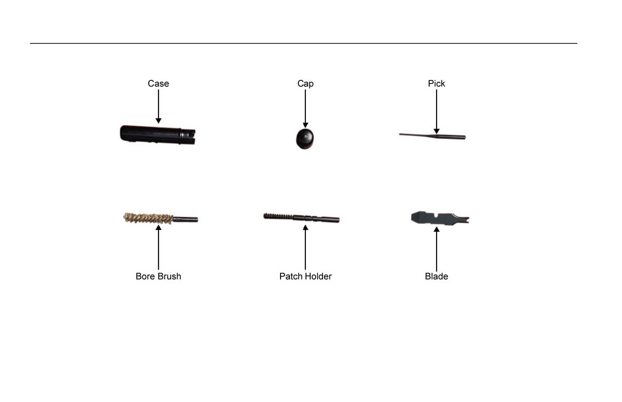
Combination Tool Kit
Ensure all the accessories are present. Refer to Figure 1.
Magazine Assembly
Check for dents, spring tension, and serviceability of the follower. Check for correct
position of cartridges in the magazine. Check that the magazine fits and releases
properly.
Sling
Check for mold, tears, cuts, and cracks. All hooks must be present. Clean with
soap and water. Let air dry.
0010 00-3
TM 8370-50007-OR/1
0010 00
For the combination tool kit accessories, refer to Figure 1.
Figure 1. Combination Tool Kit Accessories.
END OF WORK PACKAGE
0010 00-4

TM 8370-50007-OR/1
0011 00
PREVENTIVE MAINTENANCE CHECK AND SERVICES (PMCS) INTRODUCTION
GENERAL
The operator will perform Preventive Maintenance Checks and Services (PMCS) (WP 0012 00) before, during, and after
firing a 7.62 mm, AK-47 rifle, along with disassembly and reassembly procedures required for PMCS.
END OF WORK PACKAGE
0011 00-1/2 blank

INTENTIONALLY BLANK

TM 8370-50007-OR/1
0012 00
PREVENTIVE MAINTENANCE CHECKS AND SERVICES (PMCS), INCLUDING LUBRICATION INSTRUCTIONS
THIS WORK PACKAGE DESCRIBES
Preventive Maintenance Checks and Services (PMCS) Procedures and Lubrication Instructions.
INITIAL SETUP
Maintenance Level
References
Operator
WP 0005 00
WP 0014 00
Equipment Conditions
WP 0015 00
Weapon cleared (WP 0005 00)
GENERAL
The PMCS procedures are contained in the following table. They are arranged in logical sequence requiring a minimum
amount of time and motion on the part of the persons performing them, and are arranged so that there will be minimal
interference between the persons performing checks simultaneously on the same end item.
0012 00-1

TM 8370-50007-OR/1
0012 00
EXPLANATION OF COLUMNS
1. Item Number. Numbers in this column act as references. When completing an Equipment Inspection and
Maintenance Worksheet, include the item number for the check/service item. Item numbers appear in the order in
which the checks and services are to be performed.
2. Interval. This column states the designated interval when each check is to be performed.
a. BEFORE procedures are performed prior operating the weapon for its intended mission.
b. DURING procedures are performed while operating the weapon for its intended mission.
c. AFTER procedures are performed after finishing operating the weapon for its intended mission.
3. Location, Item to Check/Service. This column lists the items and locations to be checked or serviced.
4. Procedure. This column contains a brief description of PMCS procedures to be performed. The procedure must
follow the time stated in the interval column.
5. Not Fully Mission Capable if. This column states which faults will prevent the weapon from being capable of
performing its primary mission. The weapon should not be used if it meets any of the faults listed in this column.
Follow standard operating procedures for correcting or reporting weapon failure.
6. Other Table Entries. Observe all WARNINGs, CAUTIONs, and NOTEs.
0012 00-2

TM 8370-50007-OR/1
0012 00
WARNING
Confirm the weapon is unloaded, clear, and on SAFE before performing the following
procedures. Do not keep live ammunition near the work area. Failure to follow these
warnings may cause injury or death to personnel.
0012 00-3

TM 8370-50007-OR/1
0012 00
Table 1. PMCS for AK-47 Rifle.
(1)
(2)
(3)
(4)
(5)
Item
Interval
Location of
Procedure
Not Fully Mission
No.
Item to Check/Service
Capable if:
1
Before
Visual Inspection of the
Check the weapon for missing or
Parts are missing or
Weapon
damaged parts. Report missing or
damaged to the point of
damaged parts to the unit armorer.
being unserviceable.
2
During
Periodic Inspection of the
Periodically inspect the weapon to
Foreign material is in the
Weapon
ensure it is clean and there is no
bore.
foreign material in the bore. If
foreign material is present, clean the
bore.
3
Before and
Magazine
a. Verify the magazine rocks
The magazine is distorted
After
easily into the magazine well
or hard to seat in the
and locks into place.
magazine well.
b. Ensure the magazine follower
The magazine follower is
has spring tension and moves
stuck or has weak spring
easily inside the magazine.
action.
0012 00-4

TM 8370-50007-OR/1
0012 00
Table 1. PMCS for AK-47 Rifle - Continued.
(1)
(2)
(3)
(4)
(5)
Item
Interval
Location of
Procedure
Not Fully Mission
No.
Item to Check/Service
Capable if:
4
Before and
Receiver - Thread Protector
Check for looseness.
The thread protector is
After
loose.
5
Before and
Receiver - Barrel
Check for barrel looseness (using
The barrel is loose in the
After
hand pressure only).
receiver.
6
Before and
Receiver - Handguards
Check for looseness, cracks, or
The handguards are loose
After
missing parts.
on the barrel or are
damaged.
7
Before and
Receiver - Magazine
Check the magazine release for
The magazine release has
After
Release
spring tension and retention of the
no spring tension or does
magazine.
not retain or release the
magazine.
8
Before and
Receiver - Buttstock
Check for cracks, looseness, and
The buttstock is loose, has
After
missing parts.
more than three cracks, or
has any cracks near pins or
screws.
0012 00-5

TM 8370-50007-OR/1
0012 00
Table 1. PMCS for AK-47 Rifle - Continued.
(1)
(2)
(3)
(4)
(5)
Item
Interval
Location of
Procedure
Not Fully Mission
No.
Item to Check/Service
Capable if:
9
Before and
Weapon Sights
Move the front and rear sights to
The sights are damaged,
After
ensure they can be adjusted. Return
missing, or cannot be
the sights to the zero setting on the
adjusted.
weapon.
10
During
Maintenance Performed
Clean and lubricate the weapon
during Firing Operations
after firing approximately 200 rounds
of ammunition or at the day’s end.
Refer to WP 0014 00.
0012 00-6

TM 8370-50007-OR/1
0012 00
Table 1. PMCS for AK-47 Rifle - Continued.
(1)
(2)
(3)
(4)
(5)
Item
Interval
Location of
Procedure
Not Fully Mission
No.
Item to Check/Service
Capable if:
10
After
Maintenance of the Weapon
a. Disassemble the weapon. Refer
Parts are missing or
Cont.
and Equipment
to WP 0015 00.
damaged.
b. Clean and lubricate the
weapon. Refer to WP 0014 00.
c. Disassemble, inspect, and
clean the magazine. Refer to
WP 0014 00.
d. Clean and lubricate the bayonet
and scabbard. Refer to WP
0014 00.
e. Report all missing or damaged
parts to the unit armorer.
0012 00-7

TM 8370-50007-OR/1
0012 00
Table 1. PMCS for AK-47 Rifle - Continued.
(1)
(2)
(3)
(4)
(5)
Item
Interval
Location of
Procedure
Not Fully Mission
No.
Item to Check/Service
Capable if:
11
Before and
Selector Lever: SAFE
a. Unload and clear the weapon.
After
Refer to WP 0005 00.
Function
b. Place the selector lever on
The hammer falls.
Check
SAFE and pull the trigger. The
hammer should not fall.
12
Before and
Selector Lever: SEMI
a. Place the selector lever on
After
SEMI.
Function
b. Pull the trigger to the rear and
The hammer does not fall.
Check
hold. The hammer should fall.
c. Charge the weapon. Release
The hammer does not fall.
the trigger and pull it again. The
hammer should fall.
0012 00-8

TM 8370-50007-OR/1
0012 00
Table 1. PMCS for AK-47 Rifle - Continued.
(1)
(2)
(3)
(4)
(5)
Item
Interval
Location of
Procedure
Not Fully Mission
No.
Item to Check/Service
Capable if:
13
Before and
Selector Lever: AUTO
a.
Pull the charging handle to the
After
rear and release to cock the
weapon.
Function
b.
Pull the trigger and hold to the
The hammer does not fall.
Check
rear. The hammer should fall.
c.
Pull the charging handle to the
rear and release.
d.
Release the trigger and pull it
The hammer falls.
again. The hammer should not
fall.
e.
The hammer should have fallen
when the charging handle was
released and the bolt moves
forward.
0012 00-9

TM 8370-50007-OR/1
0012 00
LUBRICATION
1. Inspect Before Lubrication.
If items are found to be unsatisfactory during inspection, notify the unit armorer.
WARNING
Do not interchange bolt assemblies between weapons. Failure to follow this warning may
cause injury or death to personnel.
a. Bolt. Inspect for cracks or fractures, especially in the bolt lug area. Bolts containing pits extending into the firing
pin hole need to be replaced.
b. Firing Pin. Inspect the firing pin for a bent, cracked, blunted, or sharp end.
c. Extractor and Extractor Spring. Inspect the extractor for chipped or broken edges in the area of the lip that
engages the cartridge rim. Check the extractor spring tension.
2. Cleaner, Lubricant, and Preservative (CLP).
a. CLP performs the following:
(1) Dissolves firing residue and carbon.
(2) Provides a layer of teflon for lubrication of parts.
0012 00-10

TM 8370-50007-OR/1
0012 00
(3) Prevents rust from forming.
CAUTION
Do not dry clean the weapon. Do not use hot water or other solvents to clean the weapon.
This will remove the teflon lubricant built up as a result of using CLP.
b. Use CLP as follows:
(1) Shake the bottle well before each use.
(2) Place a few drops on a patch or rag.
(3) Clean the weapon with patches or rags until no residue is found.
(4) Use another patch or rag to apply a fresh, light coat.
0012 00-11
TM 8370-50007-OR/1
0012 00
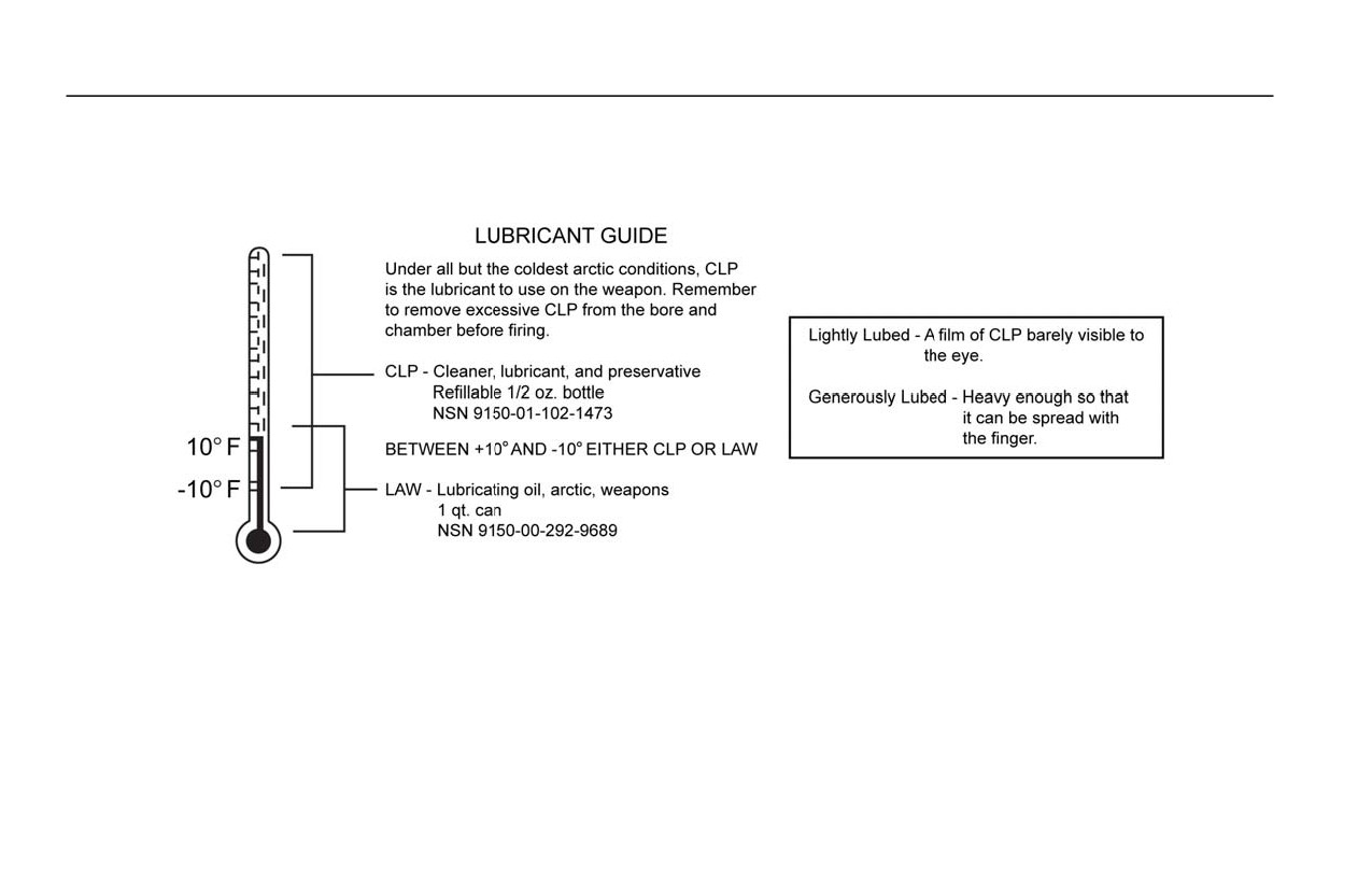
3. Lubrication. CLP is the lubricant to be used under all but the coldest arctic conditions when lubricant, arctic,
weapons (LAW) is used. Remove excessive lubricant from the bore and chamber before firing. For a lubricant guide,
refer to Figure 1.
Figure 1. Lubricant Guide.
NOTE
Dry cleaning solvents may be used to remove lubricants completely. When moving to
extreme cold weather operations, remove traces of CLP before applying LAW.
0012 00-12
TM 8370-50007-OR/1
0012 00
a. Receiver.
(1) Lightly lubricate the inside of the receiver, bore and chamber, outer surfaces of the barrel, front sight,
magazine release, gas tube, and barrel surfaces under the handguards.
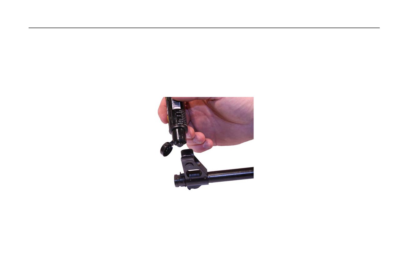
(2) Apply one drop of CLP to the front sight post, rotate to work in the CLP, wipe away excess CLP, and return
to original position. Refer to Figure 2.
Figure 2. Lubricating the Front Sight Post.
0012 00-13
TM 8370-50007-OR/1
0012 00
b. Bolt Carrier Assembly and Bolt Assembly.
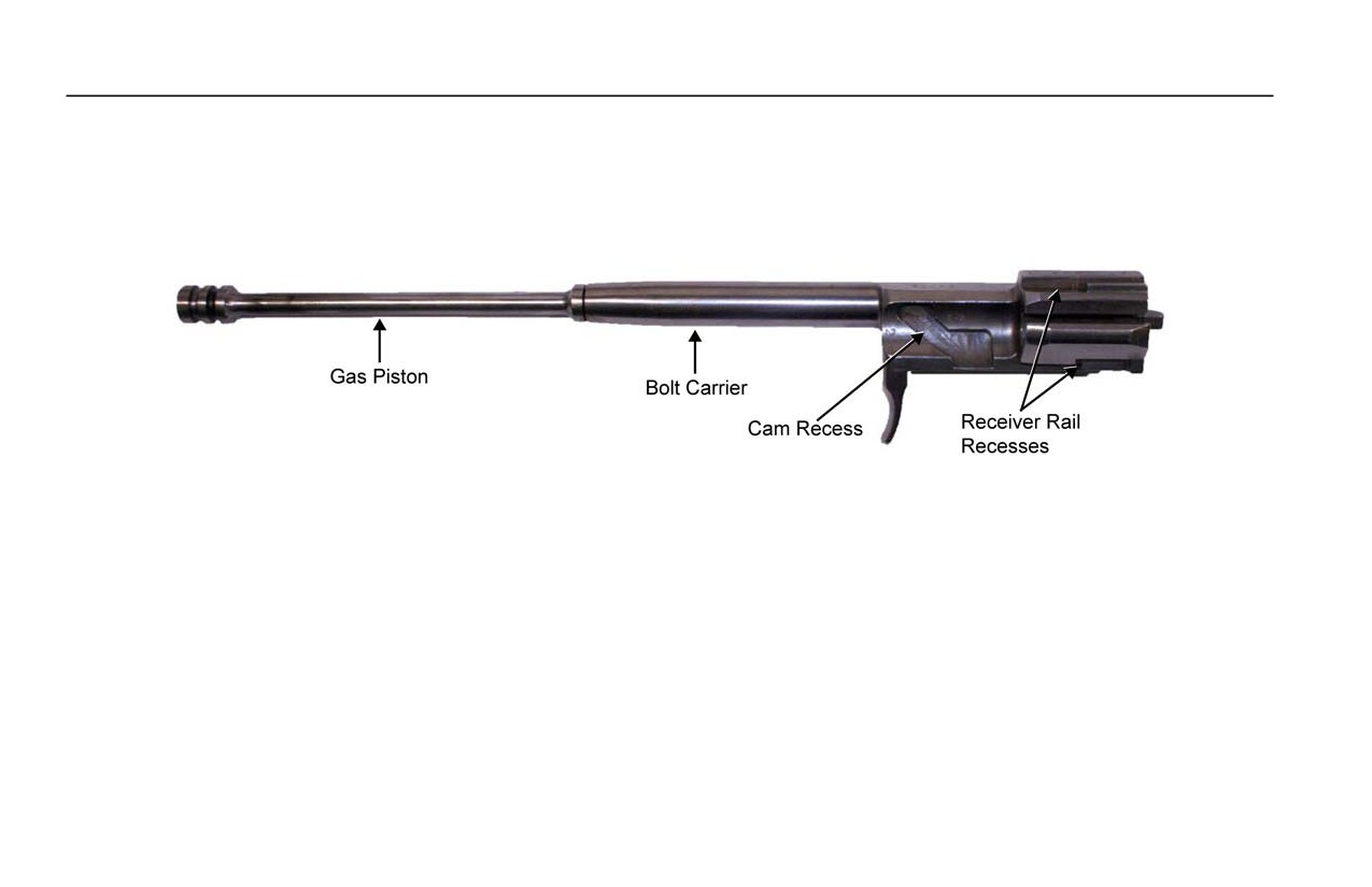
(1) Dry the bolt carrier assembly (bolt carrier and gas piston) and lightly lubricate with CLP. Generously
lubricate the cam recess and receiver rail recesses of the bolt carrier. Refer to Figure 3.
Figure 3. Bolt Carrier Assembly.
CAUTION
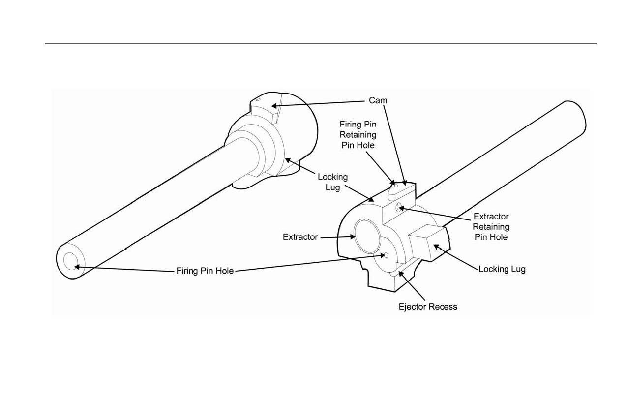
Apply only a light coat of CLP to the firing pin and firing pin hole in the bolt.
(2) LIGHTLY lubricate the firing pin and the firing pin hole in the bolt Refer to Figure 4.
0012 00-14
TM 8370-50007-OR/1
0012 00
(3) Generously lubricate the extractor, extractor retaining pin, firing pin retaining pin, and outside of the bolt.
Refer to Figure 4.
Figure 4. Bolt Assembly.
0012 00-15
TM 8370-50007-OR/1
0012 00
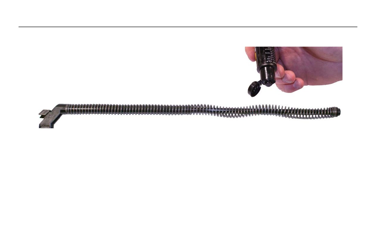
(4) Lightly lubricate the recoil spring and guide rod assembly. Refer to Figure 5.
Figure 5. Lubricating the Recoil Spring and Guide Rod Assembly.
0012 00-16
TM 8370-50007-OR/1
0012 00
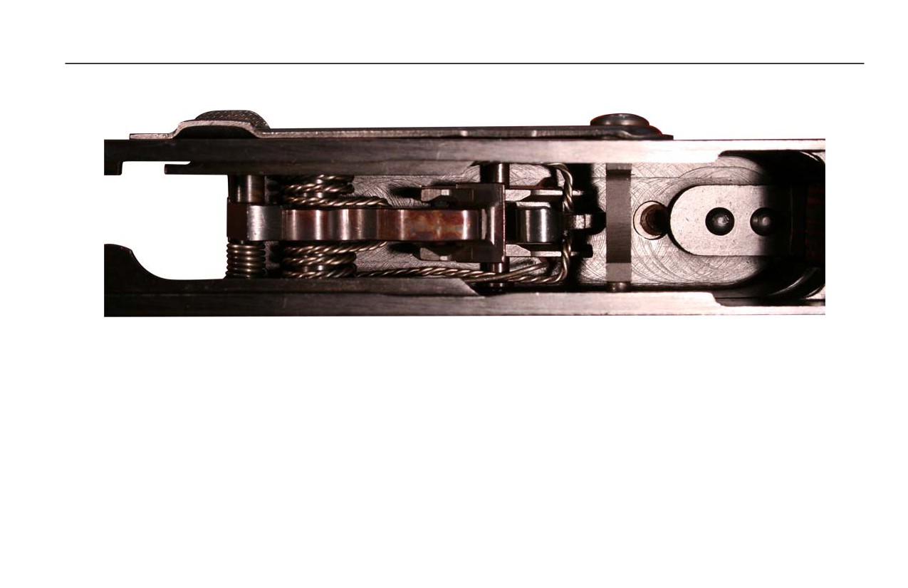
(5) Lightly lubricate all moving parts and pins inside the receiver. Refer to Figure 6.
Figure 6. Moving Parts and Pins in the Receiver.
0012 00-17
TM 8370-50007-OR/1
0012 00
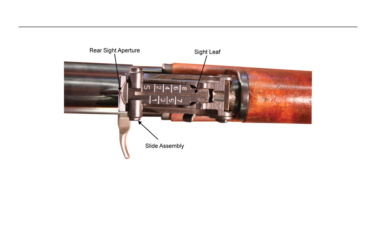
c. Rear Sight. Note the position of the sight before beginning. Refer to Figure 9
Figure 9. Rear Sight.
(1) Apply one drop of CLP to the sight leaf. Flip up and down to work in the CLP.
(2) Apply one drop of CLP to the slide assembly. Press the button several times and slide up and down the sight
leaf to work in the CLP.
(3) Reset the rear sight to its original setting.
0012 00-18

TM 8370-50007-OR/1
0012 00
NOTE
After amphibious salt water operations, thoroughly rinse the rear sight in fresh water until
the tactical situation allows for thorough cleaning and lubrication.
END OF WORK PACKAGE
0012 00-19

INTENTIONALLY BLANK

TM 8370-50007-OR/1
0013 00
GENERAL MAINTENANCE INSTRUCTIONS
THIS WORK PACKAGE DESCRIBES
Scope, Work Safety, General Information, Cleaning Instructions, Inspection Instructions, and Lubrication Instructions.
INITIAL SETUP
Maintenance Level
References
Operator
WP 0012 00
WP 0014 00
WP 0019 00
SCOPE
The following general maintenance instructions contain general shop practices and specific methods to properly maintain
the AK-47 rifle.
0013 00-1

TM 8370-50007-OR/1
0013 00
WORK SAFETY
1. Before starting a task, think about the risks and safety hazards. Wear protective gear such as safety goggles or lenses,
safety shoes, a rubber apron, and gloves.
2. Observe all WARNINGs, CAUTIONs, and NOTEs.
GENERAL INFORMATION
CAUTION
Do not mix lubricants on the same weapon. The weapon must be cleaned thoroughly
during any change from one lubricant to another. Dry cleaning solvent
(SD) is
recommended for cleaning before changing lubricants.
When the term cleaner, lubricant, and preservative (CLP) or the word lubricant is cited in this TM, it is to be interpreted to
mean that CLP, lubricating oil, semi-fluid, automatic weapons (LSA); or lubricating oil, arctic, weapons (LAW) can be
used.
1. Disassemble, thoroughly clean, inspect, and lubricate the weapon.
2. Always shake CLP prior to use.
3. After firing, clean the weapon with CLP according to instructions in WP 0014 00. Wipe the weapon dry and lubricate
according to instructions in WP 0012 00.
0013 00-2

TM 8370-50007-OR/1
0013 00
NOTE
Contact the unit armorer if parts from the cleaning kit are missing or defective.
4. Cleaning materials (e.g., patches, pipe cleaners, and CLP) are expendable items. For a complete list of cleaning
materials refer to WP 0019 00.
CLEANING INSTRUCTIONS
NOTES
Use only CLP for cleaning and lubrication in all but the most severe conditions.
Cloths or rags saturated with CLP must be disposed of in accordance with authorized
facilities’ procedures.
Cleaning instructions are the same for the majority of the parts and components of the
weapon.
0013 00-3

TM 8370-50007-OR/1
0013 00
The importance of cleaning must be thoroughly understood by operators and maintenance personnel. Great care and effort
are required in cleaning. Dirt and foreign material are a constant threat to satisfactory maintenance. The following apply
to all cleaning, inspection, repair, and assembly operations:
NOTES
Clean all parts before inspection, after repair, and before assembly.
To prevent contamination, hands should be kept free of any accumulation of grease
which can collect dust, dirt, or grit.
After cleaning, all parts should be covered or wrapped to protect them from dust and dirt.
Parts that are subject to rust should be lightly oiled.
1. Cleaning Disassembled Parts.
a. Dry and cover all cleaned parts.
b. All parts subject to rusting must be lightly oiled and wrapped.
c. Keep all related parts and components together. Do not mix parts.
2. Castings.
a. Clean the inner and outer surfaces of castings with CLP.
0013 00-4

TM 8370-50007-OR/1
0013 00
b. Use a stiff brush to remove sludge and gum deposits.
3. Machined Surfaces.
a. Clean machined surfaces with CLP.
b. Dry surfaces thoroughly.
4. Mated Surfaces. Lightly coat with CLP and wrap all parts subject to rust before storing.
INSPECTION INSTRUCTIONS
1. General. All components and parts must be checked carefully to determine if they are serviceable for reuse or if they
must be scrapped.
2. Castings.
a. Replace all cracked castings.
b. Inspect machined surfaces for nicks, burrs, or raised metal. Mark damaged areas for repair or replacement.
c. Inspect all screws and screw openings for damaged or stripped threads.
3. Machine-Tooled Parts. Inspect for cracks, breaks, elongated holes, wear, and chips.
0013 00-5

TM 8370-50007-OR/1
0013 00
4. Machined Surfaces. Inspect for cracks, evidence of wear, galled or pitted surfaces, burrs, nicks, and scratches.
5. Mating Surfaces. Inspect mating surfaces for seal, secure fit, and pitting.
6. Rusted Surfaces. Inspect for pitting, holes, and severe damage.
7. Internal Parts. Inspect for cracks, nicks, burrs, evidence of overheating, and wear.
8. Externally Exposed Parts. Inspect for breaks, cracks, rust damage, and wear.
9. Springs. Inspect for broken, collapsed, and twisted coils.
LUBRICATION INSTRUCTIONS
Refer to PMCS (WP 0012 00) for detailed, illustrated instructions on proper lubrication. The following are some general
practices to remember:
1. Use the correct lubricant.
2. Keep lubricants clean.
3. Lubricate clean, disassembled, and new parts to prevent rust.
END OF WORK PACKAGE
0013 00-6

TM 8370-50007-OR/1
0014 00
WEAPON CLEANING
THIS WORK PACKAGE DESCRIBES
Field Expedient Cleaning, Detailed Cleaning, and Thorough Cleaning.
INITIAL SETUP
Maintenance Level
References
Operator
WP 0005 00
WP 0015 00
Materials/Parts
WP 0019 00
WP 0020 00
Cleaner, lubricant, and preservative (CLP)
Cleaner, tobacco pipe
Equipment Conditions
Patch, small caliber, 7.62 mm
Patch, small caliber, 7.62 mm, round
Weapon field stripped (WP 0015 00)
Rag, wiping
0014 00-1

TM 8370-50007-OR/1
0014 00
WARNING
Ensure the weapon is clear before performing the following procedures. DO NOT
interchange parts from one weapon to another. Failure to follow this warning may cause
injury or death to personnel.
CLEANING THE WEAPON
Cleaning is part of scheduled maintenance and should always begin with an inspection of the weapon. Use the equipment
listed in WP 0019 00 for cleaning and lubrication. The weapon should be cleaned within two hours of firing or as soon as
the tactical situation permits.
1. Field Expedient Cleaning.
NOTE
After cleaning and before reassembly, lightly lubricate all parts with CLP.
a. Clear the weapon. Refer to WP 0005 00.
b. Check the bore and chamber for fouling.
c. Remove the bolt carrier assembly and bolt assembly. Refer to WP 0015 00.
d. Clean carbon and oil from the firing pin and all surfaces of the bolt and bolt carrier with clean, dry rag.
e. Clean the firing pin hole.
0014 00-2
TM 8370-50007-OR/1
0014 00
f.
Apply a light coat of CLP. Give special attention to the cam recess and receiver rail recesses.
g. Swab the bore with a patch with CLP.
CAUTION
Ensure that the patch goes completely through the muzzle. Do not reverse the direction
while the patch is in the bore or muzzle.
The bore of the weapon has lands and grooves called rifling. Allow the cleaning rod to rotate (following the
rifling grooves) as it is pulled through the bore. This will provide better cleaning of the bore and rifling grooves.
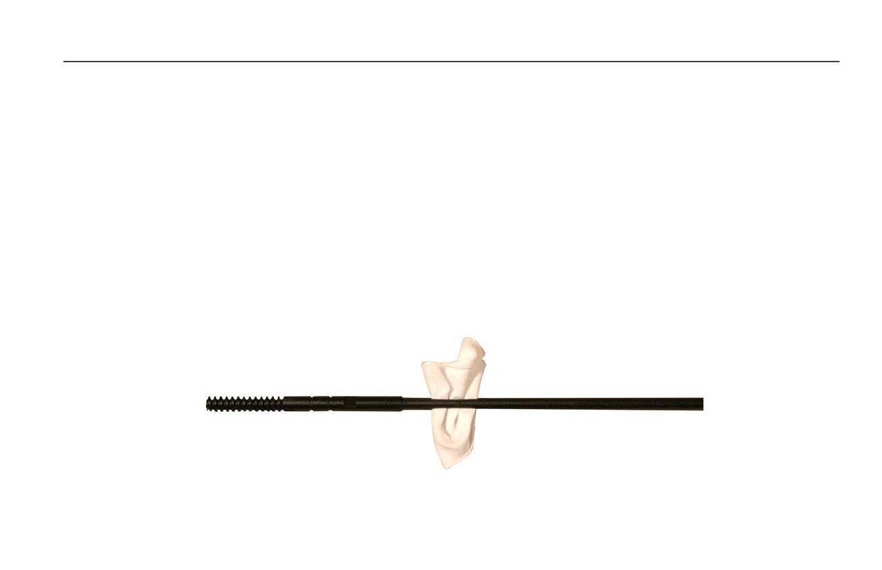
(1) Attach the patch holder to the cleaning rod and insert a clean patch in the patch holder. Apply several drops
of CLP to the patch. Refer to Figure 1.
Figure 1. Cleaning Rod with Patch Holder Attached and Patch Inserted.
0014 00-3
TM 8370-50007-OR/1
0014 00
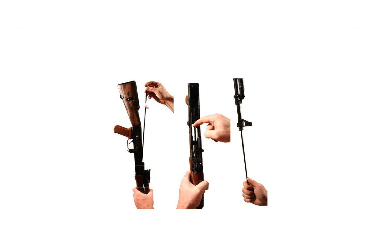
(2) Point the muzzle down. Holding the receiver in one hand, insert the end of the rod without the patch holder
into the chamber. Allow the rod to fall straight through the bore. Two to three inches will stick out of the
muzzle.
(3) Pull the cleaning rod out the muzzle. The rod will twist as it is pulled through. Refer to Figure 2.
Figure 2. Swabbing the Bore.
0014 00-4

TM 8370-50007-OR/1
0014 00
2. Detailed Cleaning Techniques - Standard Kit. To perform detailed cleaning techniques with a standard kit, use the
following instructions:
CAUTION
When using the bore brush, do not reverse the direction while the brush is in the bore.
a. Swab the bore with a patch with CLP as described in Field Expedient Cleaning in this work package.
b. Replace the patch and patch holder with the bore brush. Refer to Figure 3.
Figure 3. Bore Brush.
c. Re-insert the cleaning rod into the chamber, down through the bore.
0014 00-5
TM 8370-50007-OR/1
0014 00
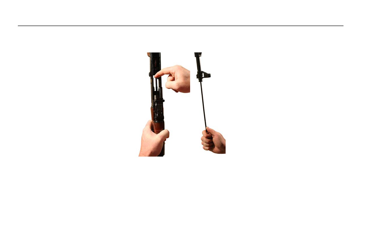
d. Pull the bore brush through the bore and out of the muzzle. The rod will twist as it is pulled through. Refer to
Figure 4.
Figure 4. Running the Bore Brush though the Bore and out of the Muzzle.
e. Repeat the process several times.
f.
Occasionally, pull a patch with CLP through the bore to help remove dirt and debris loosened by the bore brush.
Always have the bore wet with CLP prior to pulling the bore brush through the barrel.
0014 00-6

TM 8370-50007-OR/1
0014 00
3. Detailed Cleaning Techniques - with an Otis Kit.
a. Attach the bore obstruction remover tip to one end of the flexible cleaning rod and attach the slotted tip to the
other end of the rod.
b. Place the slotted tip into an outside hole on a cleaning patch.
NOTE
The size of the patch may be varied by pinching the patch in locations further away from
the slot.
c. Pinch a portion of the patch and insert it through the slot in the slotted tip. Pull it tight to tie the knot and ensure
that the patch scrubs efficiently.
d. Turn the outer edge of the patch down over itself.
NOTE
If done correctly, the patch forms a symmetrical cone centering it in the bore, ensuring
360° cleaning occurs. Always use a clean patch each time it is passed through the bore.
e. Apply three to five drops of CLP to the front end of the knot in the patch. Do not dip the patch into the CLP.
f.
Insert the bore obstruction remover tip and flexible cleaning rod into the chamber until the patch enters the
receiver.
0014 00-7

TM 8370-50007-OR/1
0014 00
g. Use the patch to mop out the receiver and slides.
h. Hold the flexible cleaning rod by the knurled bore obstruction remover and rotate the rod as the patch enters the
locking lugs. Use fingers or the cleaning brush to force the patch into the recess in front of the locking lugs.
NOTE
Give special attention to the following areas in step i, particularly if the weapon has been
firing blank rounds.
i.
Continue to turn the patch as it passes through the chamber and enters the neck area.
j.
Continue to pull the flexible cleaning rod and patch through the barrel until the patch exits the muzzle.
k. Remove the patch and slotted tip from the flexible cleaning rod.
l.
Attach the chamber brush to one end of the short chamber cleaning rod and the T-handle to the other end.
m. Cover the chamber brush with a used patch. Mop out the locking lugs and chamber while turning it in a clockwise
direction with the T-handle. Let the brush feed itself into the chamber.
n. Give the brush and patch several turns while in the chamber, ensuring the shoulder of the chamber is cleaned.
o. Turn and pull the brush and patch from the chamber.
p. Attach the bore brush to the flexible cleaning rod.
0014 00-8

TM 8370-50007-OR/1
0014 00
NOTE
Do not push the bore brush into the bore at first.
q. Insert the flexible cleaning rod into and down through the bore.
r.
Turn the flexible rod as the bore brush enters the chamber and into the neck so that the brush can be felt scrubbing
the shoulder of the neck.
s. Pull the bore brush into and through the bore in a “breech-to-muzzle” direction.
t.
Using a clean, dry patch for each pass through the chamber and bore, repeat steps f through k.
u. If the patch does not come out clean, repeat steps p through s until the patch comes out clean.
0014 00-9

TM 8370-50007-OR/1
0014 00
4. Thorough Cleaning.
a. Receiver. Clean with CLP.
(1) Clean all areas of powder fouling, corrosion, dirt, debris, and rust.
(2) Clean the chamber, locking lugs, and gas block.
(3) Bore. Clean as described in Detailed Cleaning Techniques - Standard Kit in this work package.
(4) Handguards. Remove and wipe the handguards with a cloth.
(5) Front and Rear Sights. Clean the front and rear sights with a brush and CLP.
b. Bolt Carrier Assembly and Bolt Assembly.
(1) Scrub the outer and inner surfaces of the bolt carrier and gas piston with a well worn bore brush and CLP.
(2) Clean the firing pin hole (using a pipe cleaner) and firing pin with CLP.
(3) Check the extractor for spring tension and clean any carbon and debris from under the extractor lip.
(4) Apply CLP to the extractor and depress it several times to work in the CLP.
0014 00-10

TM 8370-50007-OR/1
0014 00
c. Magazine.
(1) Disassemble the magazine. Refer to WP 0015 00.
(2) Clean with CLP. Wipe dirt from the body, spring, follower, locking plate, and base.
(3) Lightly lubricate the spring.
(4) Reassemble the magazine. Refer to WP 0015 00.
END OF WORK PACKAGE
0014 00-11/12 blank

INTENTIONALLY BLANK

TM 8370-50007-OR/1
0015 00
WEAPON MAINTENANCE (FIELD STRIPPING AND REASSEMBLY)
THIS WORK PACKAGE DESCRIBES
Weapon Disassembly/Field Stripping and Reassembly, Magazine Disassembly and Reassembly.
INITIAL SETUP
Equipment Conditions
References
Weapon cleared (WP 0005 00)
WP 0005 00
DISASSEMBLY/FIELD STRIPPING OF THE WEAPON
WARNING
Ensure the weapon is clear and on SAFE before performing these procedures. Failure to
follow this warning may cause injury or death.
1. Clear the weapon. Refer to WP 0005 00.
2. Remove the sling.
0015 00-1
TM 8370-50007-OR/1
0015 00
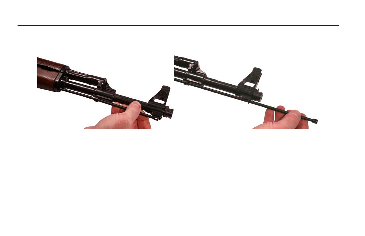
3. Remove the cleaning rod by pulling it down and away from the barrel until the head is clear of the stop under the front
sight base. Pull the cleaning rod forward until it is free from the weapon. Refer to Figure 3.
Figure 3. Removing the Cleaning Rod.
0015 00-2
TM 8370-50007-OR/1
0015 00
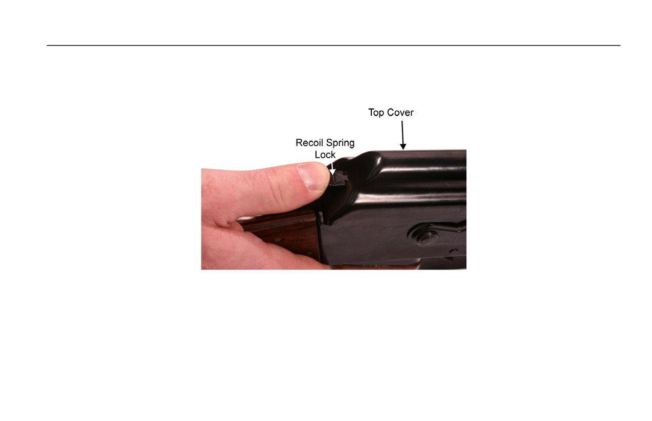
4. Remove the Top Cover.
a. Push in on the recoil spring lock until it clears the hole in the top cover. Refer to Figure 4.
Figure 4. Pushing in the Recoil Spring Lock.
0015 00-3
TM 8370-50007-OR/1
0015 00
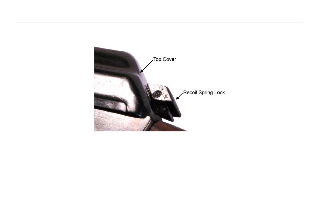
b. Some models have a two-piece recoil spring lock that needs to be pushed down, then in to disengage the recoil
spring lock from the hole in the top cover. Refer to Figure 5.
Figure 5. Two-Piece Recoil Spring Lock.
0015 00-4
TM 8370-50007-OR/1
0015 00
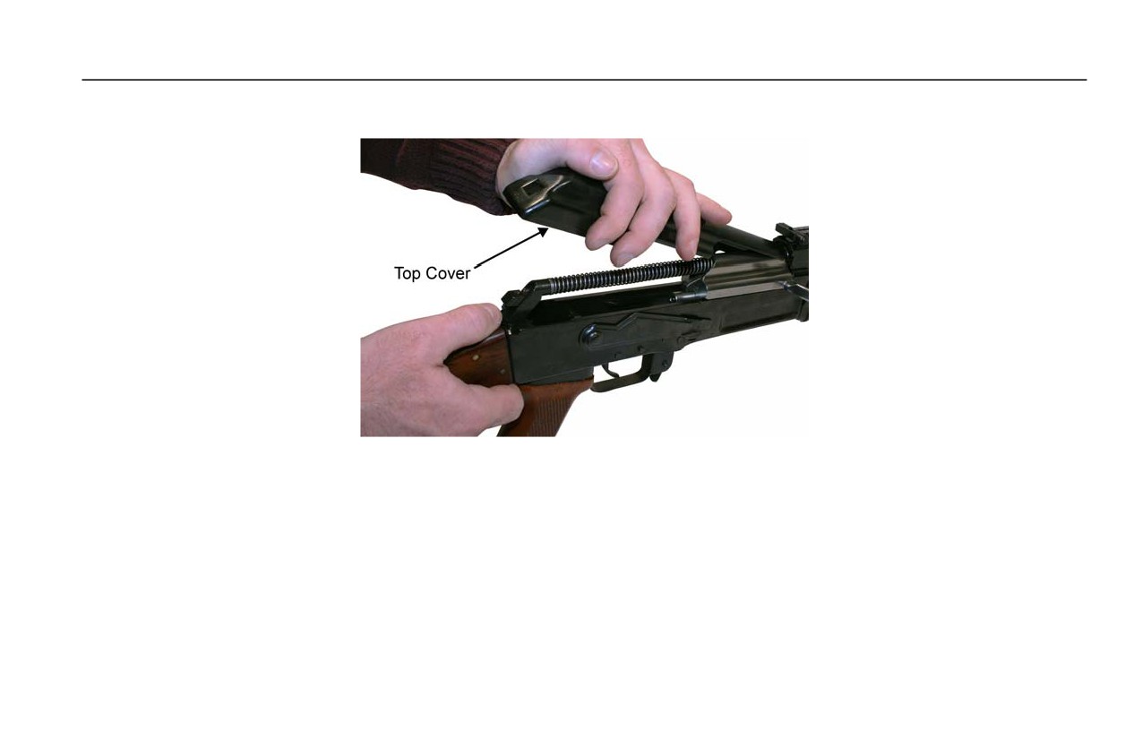
c. Pull the top cover up and to the rear to remove it from the receiver. Refer to Figure 6.
Figure 6. Lifting and Removing the Top Cover.
0015 00-5
TM 8370-50007-OR/1
0015 00
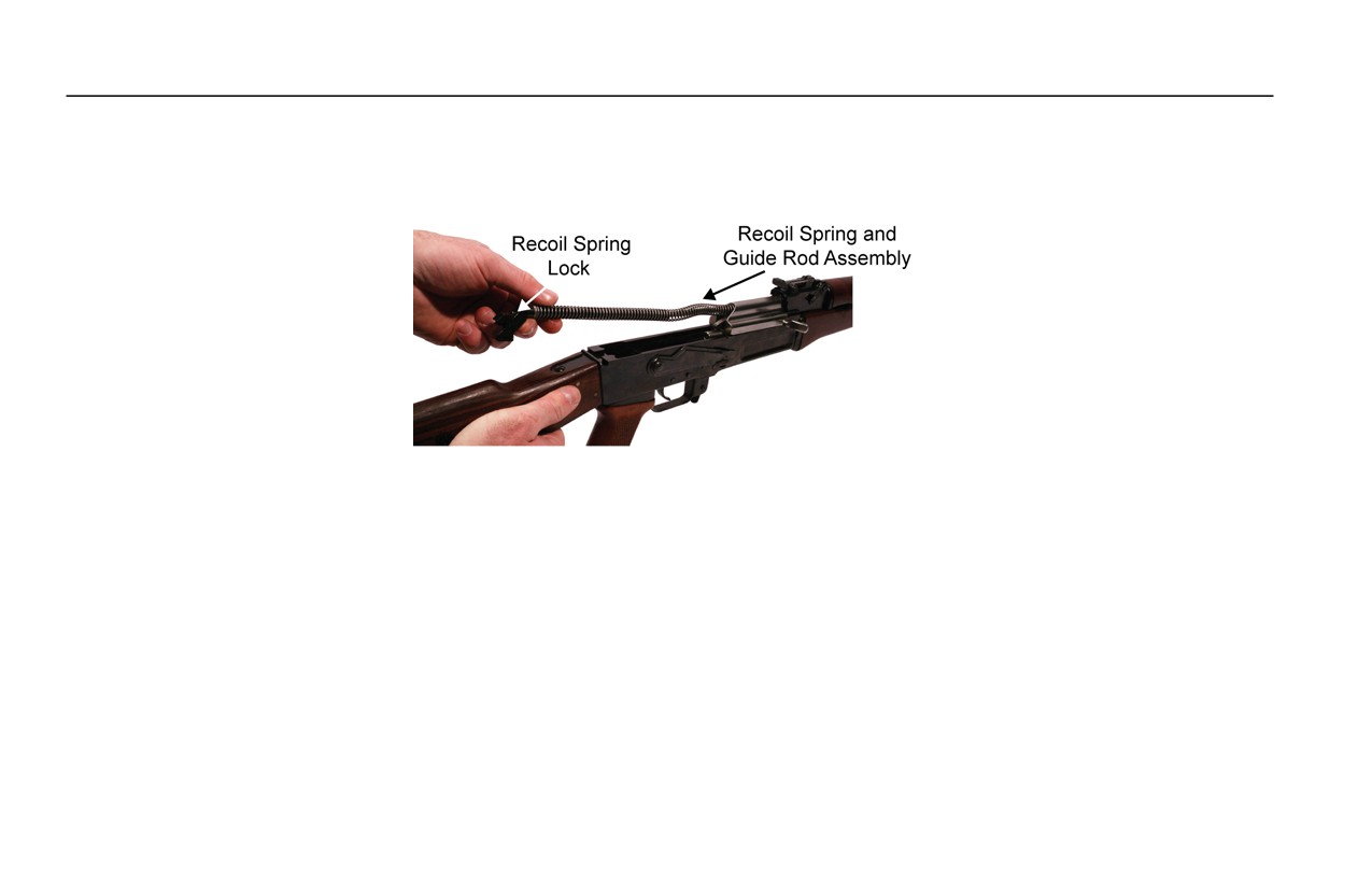
5. Remove the recoil spring and guide rod assembly by pushing forward on the recoil spring lock until it clears the lock
recess in the rear of the receiver. Lift the the recoil spring and guide rod assembly up and pull it back. Refer to
Figure 7.
Figure 7. Lifting the Recoil Spring and Guide Rod Assembly Up and Out of the Receiver.
0015 00-6
TM 8370-50007-OR/1
0015 00
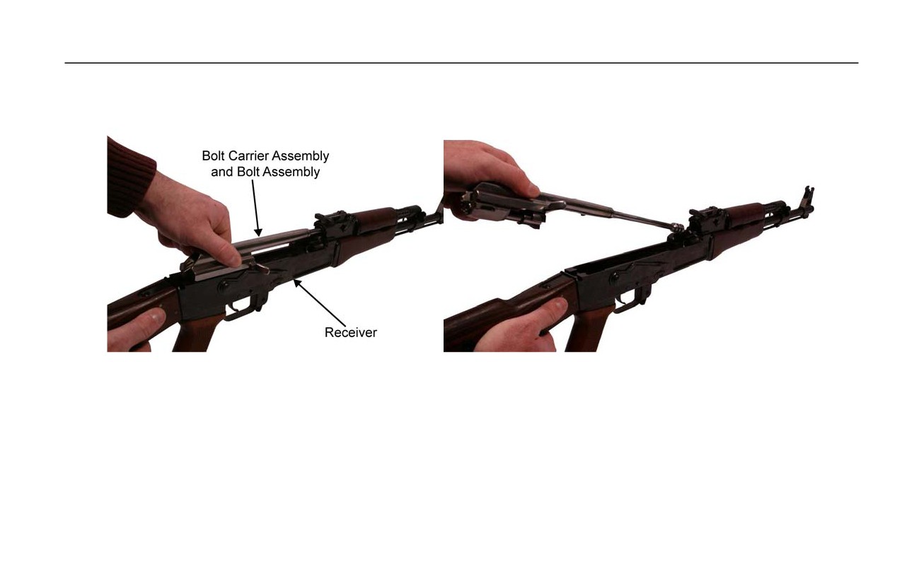
6. Remove the bolt carrier assembly and bolt assembly by sliding the bolt carrier to the rear of the receiver and pulling it
up and to the rear, out of the rear of the receiver. Refer to Figure 8.
Figure 8. Removing the Bolt Carrier Assembly and Bolt Assembly.
0015 00-7
TM 8370-50007-OR/1
0015 00
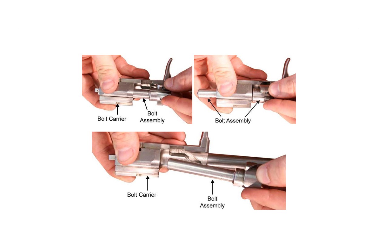
7. Remove the bolt assembly by pushing it to the rear of the bolt carrier, turning it until the bolt cam comes out of the
cam recess in the bolt carrier, and pulling the bolt assembly out (toward the gas piston). Refer to Figure 9.
Figure 9. Removing the Bolt Assembly.
0015 00-8
TM 8370-50007-OR/1
0015 00
8. Remove the Gas Tube and Handguard.
NOTES
Occasionally, the gas tube and handguard is very tight and may require a light tap to
move the locking lever from the locked down position to the unlocked up position.
Ensure the flat surface of the locking lever axle is perpendicular to the receiver to allow
adequate clearance for the gas tube and handguard.
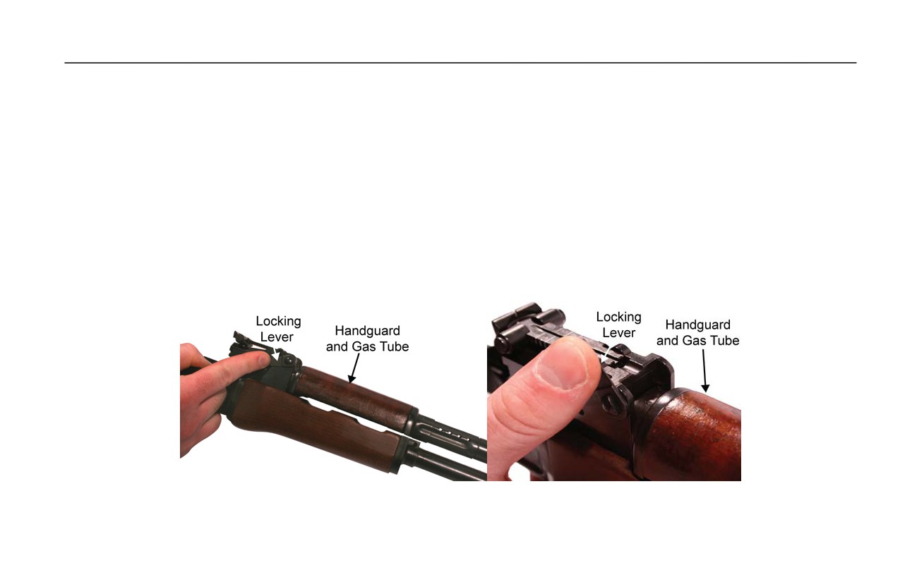
a. To remove the gas tube and handguard, push upward on the locking lever until it clears the rear of the gas tube
and handguard. Refer to Figure 10.
Figure 10. Pushing the Locking Lever to the Up Position.
0015 00-9
TM 8370-50007-OR/1
0015 00
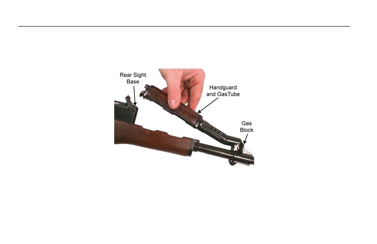
b. Unseat the rear of the gas tube and handguard from the rear sight base.
c. Pull up and to the rear on the gas tube and handguard to disengage and remove it from the gas block. Refer to
Figure 11.
Figure 11. Removing the Gas Tube and Handguard.
0015 00-10
TM 8370-50007-OR/1
0015 00
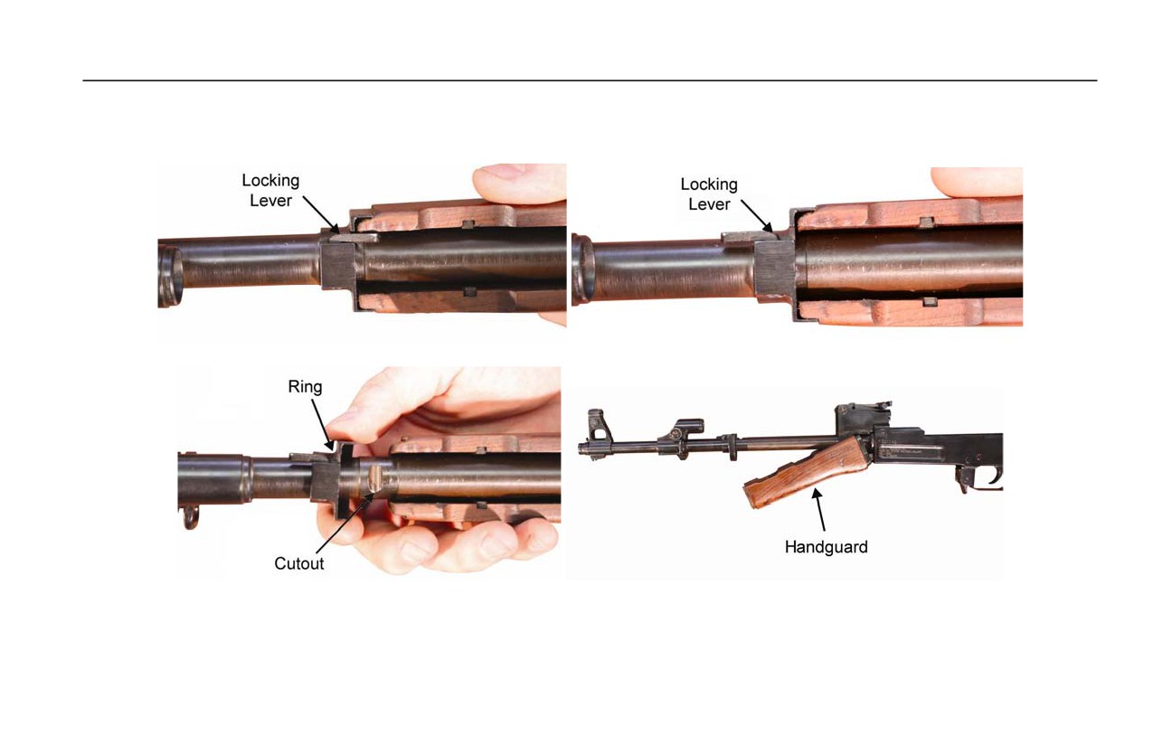
9. To remove the handguard, swing the locking lever forward. Refer to Figure 12. Slide the ring forward and remove the
handguard. Refer to Figure 12. It may be necessary to use a field expedient tool to move the locking lever.
Figure 12. Removing the Handguard.
0015 00-11