FM 3-20.98 Reconnaissance and Scout Platoon (AUGUST 2009) - page 5
Orders and Reports
“APACHE X-RAY, THIS IS RED 4. YELLOW 1. LINE 12: ALPHA. LINE 33:
BRAVO. LINE 38: CHARLIE. LINE 55: CHARLIE. OVER.”
Figure A-13. Sample ESTAT
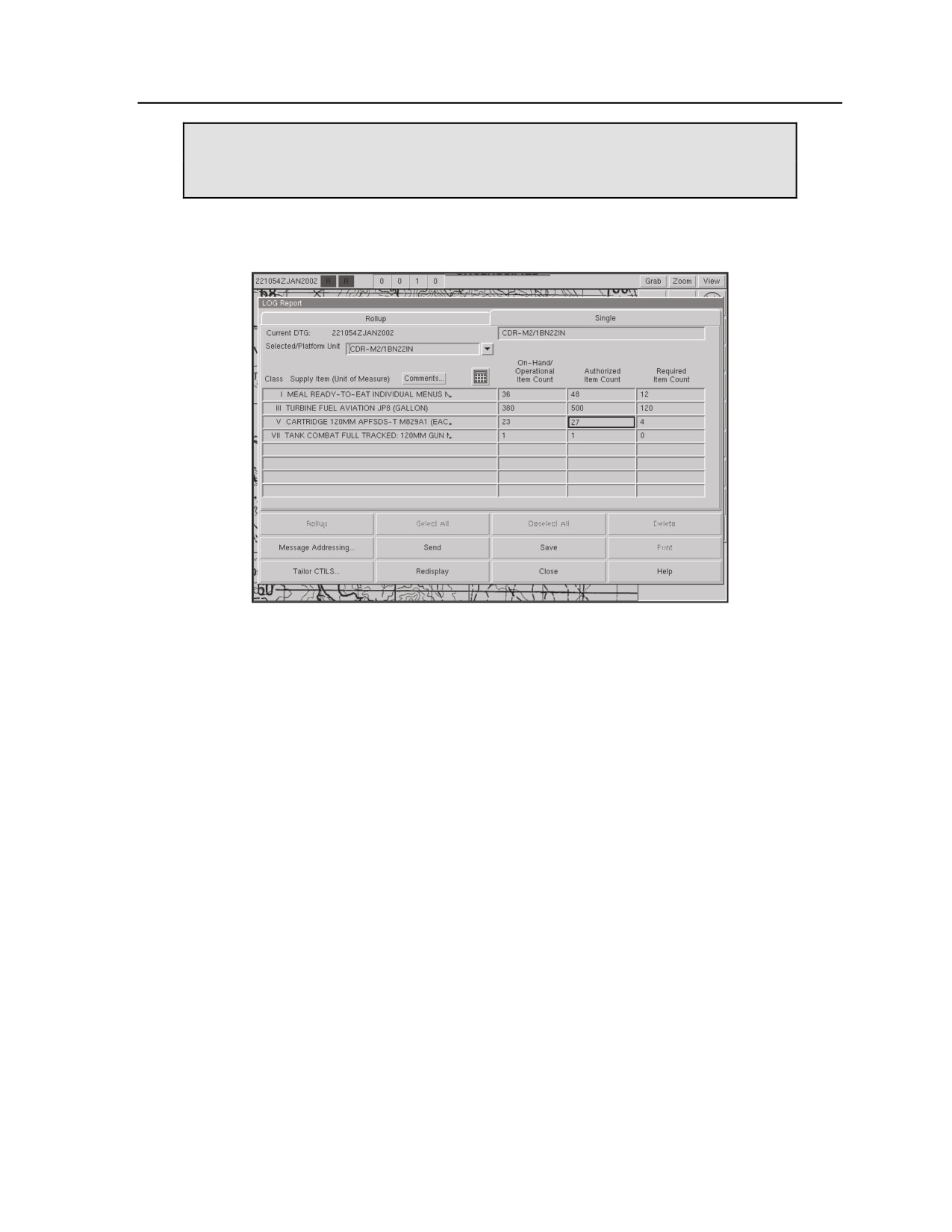
Figure A-14. Digital Yellow report (logistics report)
Yellow 1A - Battle Loss Spot Report
When Used
A-61. The Yellow 1A report is transmitted by the platoon leader or PSG as soon as possible after items are
lost or damaged in an operation. Losses are reported using line numbers from the Yellow 1 report.
Format
A-62. Provide pertinent information on the following lines:
z
Line 1: Time of loss.
z
Line 2: Number of pieces of equipment to be evacuated to troop/battalion or higher for
maintenance. Refer to the appropriate line numbers from the Yellow 1 report.
z
Line 3: Number of pieces of equipment destroyed and abandoned in pieces. Refer to the
appropriate line numbers from the Yellow 1 report.
z
Line 4: Location (encoded) of abandoned equipment.
3 August 2009
FM 3-20.98
A-23
Appendix A
Example
A-63. Figure A-15 shows an example of a battle loss spot report.
“BLACK 6, THIS IS RED 4. YELLOW ONE ALPHA, BREAK. LINE 1: ONE FOUR
THREE ZERO HOURS. LINE 2: REFERENCE SIX SLANT ONE; REFERENCE
TWO-NINER SLANT THREE. LINE 3: REFERENCE TWO-NINER SLANT ONE.
LINE 4: I SET VB, IDVRTG.”
Figure A-15. Sample battle loss spot report
Note. Yellow 1A reports are not cumulative. A Yellow 1 report showing total unit status is sent
daily not later than 1300 hours. It gives equipment status as of 1200 hours that day.
Yellow 2 - Ammunition Status Report
A-64. This report is transmitted once daily in accordance with SOP or immediately upon completion of
enemy contact. The following status codes are used:
z
GREEN: 90% or more on hand, all ammunition types.
z
AMBER: 80% to 89% on hand, all ammunition types.
z
RED: 60% to 79% on hand, all ammunition types.
z
BLACK: 59% or less on hand, all ammunition types.
Note. BLACK status in a Yellow 2 report requires immediate follow-up with a Yellow 2A
report. GREEN, AMBER, or RED status does not require submission of a Yellow 2A.
Yellow 2A - Ammunition Request
Format
A-65. The required quantity of each type of ammunition will be requested using the following line
numbers:
z
Line 1: Report as-of DTG.
z
Line 2: 105-mm/120-mm, HEAT.
z
Line 3: 105-mm/120-mm, HEP.
z
Line 4: 105-mm/120-mm, APERS.
z
Line 5: 105-mm/120-mm, WP.
z
Line 6: 105-mm/120-mm, APDS.
z
Line 7: 40-mm, HEDP.
z
Line 8: Caliber .50 (M85).
z
Line 9: Caliber .50 (M2).
z
Line 10: 25-mm.
z
Line 11: 7.62-mm (coax/M60).
z
Line 12: 120-mm HE with fuze.
z
Line 13: 120-mm WP with fuze.
z
Line 14: 120-mm illumination with fuze.
z
Line 15: 81-mm, HE with fuze.
z
Line 16: 81-mm, WP with fuze.
A-24
FM 3-20.98
3 August 2009
Orders and Reports
z
Line 17: 81-mm, illumination with fuze.
z
Line 18: Fuze, prox (4.2-inch).
z
Line 19: Fuze, PD (4.2-inch).
z
Line 20: Fuze, prox (81-mm).
z
Line 21: Fuze, PD (8l-mm).
z
Line 22: Fuze, blast, time.
z
Line 23: Blasting cap, nonelectric.
z
Line 24: Fuze, igniter.
z
Line 25: 5.56-mm ball.
z
Line 26: 5.56-mm tracer.
z
Line 28: Grenade, fragmentation.
z
Line 29: Grenade, obscurant munitions.
z
Line 30: Grenade, thermite.
z
Line 31: Grenade, 40-mm, HE.
z
Line 32: Grenade, 40-mm, WP.
z
Line 33: Grenade, 40-mm, AP.
z
Line 34: Javelin.
z
Line 35: AT-4.
z
Line 36: Dragon.
z
Line 37: TOW.
z
Line 38: Stinger missile.
z
Line 39: Mine, AT.
z
Line 40: Mine, AP.
z
Line 41: Mine, Claymore.
z
Line 42: 25-mm HE.
z
Line 43: 25-mm AP.
z
Line 44: 165-mm HE (CEV)
Note. All Yellow 2A requests will be for the quantity of ammunition required by the platoon
unless otherwise specified.
Note. When sending a Yellow 2A report, use only the lines required for specific requests.
Additional lines (beginning with Line 45) are used to request any other types of ammunition
required by the platoon. Attached units should coordinate with the S4 for additional line
numbers for their ammunition requirements.
Example
A-66. Figure A-16 shows an example of an ammunition request.
“APACHE X-RAY, THIS IS RED 4. YELLOW TWO ALPHA, BREAK. LINE 1:
112000NOV07. LINE 37: 12. LINE 42: 600. OVER.”
Figure A-16. Sample ammunition request
3 August 2009
FM 3-20.98
A-25
Appendix A
Yellow 3 - POL Status Report
When Used
A-67. This report is sent twice daily or as required.
Format
A-68. The following status codes are used:
z
GREEN: 90% or more of the required quantity on hand.
z
AMBER: 80% to 89% on hand.
z
RED: 60% to 79% on hand.
z
BLACK: 59% or less on hand.
Example
A-69. Figure A-17 shows an example of a POL status report.
“APACHE X-RAY, THIS IS RED 4. YELLOW THREE, AMBER, OVER.”
Figure A-17. Sample POL status report
Yellow 3A - POL Request
Format
A-70. The required quantity of each type of POL product will be requested using the following line numbers:
z
Line 1: Report as-of DTG.
z
Line 2: MOGAS (gal).
z
Line 3: Diesel (gal).
z
Line 4: Oil, OE-10 (gal).
z
Line 5: Oil, OE-30 (gal).
z
Line 6: Oil, OE-50 (gal).
z
Line 7: Oil, OE-90 (gal).
z
Line 8: Antifreeze (gal).
z
Line 9: Brake fluid (gal).
z
Line 10: Hydraulic fluid, OHA (qt).
z
Line 11: Hydraulic fluid, OHT (qt).
z
Line 12: Hydraulic fluid, FRH (qt).
z
Line 13: Oil, penetrating (qt).
z
Line 14: Oil, PL-special (qt).
z
Line 15: Oil, PL-medium (qt).
z
Line 16: Bore cleaner (gal).
z
Line 17: Oil, LSA (qt).
z
Line 18: Grease, GAA (lb).
z
Line 19: Grease, wheel bearing (lb).
z
Line 20: Solvent (gal).
Note. Additional lines (beginning with Line 21) are used to request any other POL products
required by the platoon or attached elements.
A-26
FM 3-20.98
3 August 2009
Orders and Reports
Example
A-71. Figure A-18 shows an example of a POL request.
“APACHE X-RAY, THIS IS RED 1. YELLOW THREE ALPHA, BREAK. LINE 1:
112000 NOV. LINE 3: 900. LINE 8: 15.”
Figure A-18. Sample POL request
RED REPORTS (PERSONNEL)
Red 2 - Personnel Battle Loss Report
When Used
A-72. A Red 2 report is transmitted to the troop CP as casualties occur. The unit must also complete DA
Form 1156 (Casualty Feeder Card), with witness statements, and submit them to the 1SG.
Format
A-73. Provide all pertinent information using the following lines:
z
Line 1: Unit roster number.
z
Line 2: DTG of the incident.
z
Line 3: Location of the incident (encoded).
z
Line 4: Type of casualties, encoded by letter as follows:
ALPHA: KIA, hostile action.
BRAVO: KIA, nonhostile action.
CHARLIE: Body recovered.
DELTA: Body not recovered.
ECHO: Body identified.
FOXTROT: Body not identified.
GOLF: Missing in action.
HOTEL: Captured.
INDIA: WIA, slight, hostile action.
JULIET: WIA, serious, hostile action.
KILO: WIA, slight, nonhostile action.
LIMA: WIA, serious, nonhostile action.
MIKE: Accident.
z
Line 5: Location to which casualties are evacuated.
Red 3 - Medical Evacuation Request
When Used
A-74. A Red 3 report is sent to the medical team on the troop command net to request MEDEVAC support.
When aerial MEDEVAC is not available, scouts should use a ground MEDEVAC format. Unit may
provide this alternate report format in local SOPs. A ground MEDEVAC should contain the listed
information.
Note. The digital Red 3 MEDEVAC request (see Figure A-19) is sent to the PSG, 1SG, medics,
and maintenance team.
3 August 2009
FM 3-20.98
A-27

Appendix A
Figure A-19. Digital Red 3 report
Ground Evacuation Format
A-75. Provide pertinent information on the following lines:
z
Line 1: State “EVAC.”
z
Line 2: Location for pickup (encoded).
z
Line 3: Number of casualties.
z
Line 4: Category of patient condition, encoded by letter designation as follows:
ALPHA: Urgent.
BRAVO: Priority.
CHARLIE: Routine.
Note. Use the letter designation with the number of patients in each category; for example,
“TWO ALPHA” indicates that two patients require evacuation on an urgent basis.
Air Evacuation Format
A-76. Use the information format in Figure A-20 for an air evacuation.
A-28
FM 3-20.98
3 August 2009
Orders and Reports
Medical Evacuation/Aero-Medical MEDEVAC
MEDEVAC FREQ:
Line 1
Grid
Line 2
Unit frequency, Call Sign, Suffix
Line 3
Number of Patients by Precedence:
Urgent
Urgent/Surgical
Priority
Line 4
Special Equipment:
Aircraft Rescue Hoist
Jungle/Forest Penetrator
Semirigid Litter
Strokes Basic Litter
Kendrick Extraction Device
Jaws of Life
Line 5
Number of Patients by Type:
L = Litter
A = Ambulatory
Note. Once complete with Lines 1 through 5, the MEDEVAC
can fly. Continue with remainder of report when you can.
Line 6
If in Wartime:
N = No Enemy in Area
P = Possible Enemy in Area
E = Enemy in Area
X = Enemy in Area, Escort Required
If in Peacetime: (Type of injury)
Gunshot
Broken Bones
Illness, etc.
Line 7
Method of Marking Site:
A = VS-17
B = Pyrotechnics
C = Obscurant munitions
D = None
E = Other
Line 8
Patient Nationality and Status
(Military/Nonmilitary)
Line 9
CBRN Contamination:
Y = Yes
N = No
Description of Terrain at Pick-Up Site
Figure A-20. Air MEDEVAC request format
3 August 2009
FM 3-20.98
A-29
Appendix A
NBC REPORTS
A-77. All shelling and NBC reports are forwarded to the troop CP over the command net.
z
NBC-1. Used by the observing unit to report initial and subsequent data of a NBC attack.
z
NBC-2. Used for passing evaluated data of a CBRN attack.
(Note. The format for the NBC-2
report is not included here.)
z
NBC-3. Used for immediate warning of expected CBRN contamination.
z
NBC-4. Used to report radiation dose rate measurements.
z
NBC-5. Used to report locations of CBRN contamination or hazards.
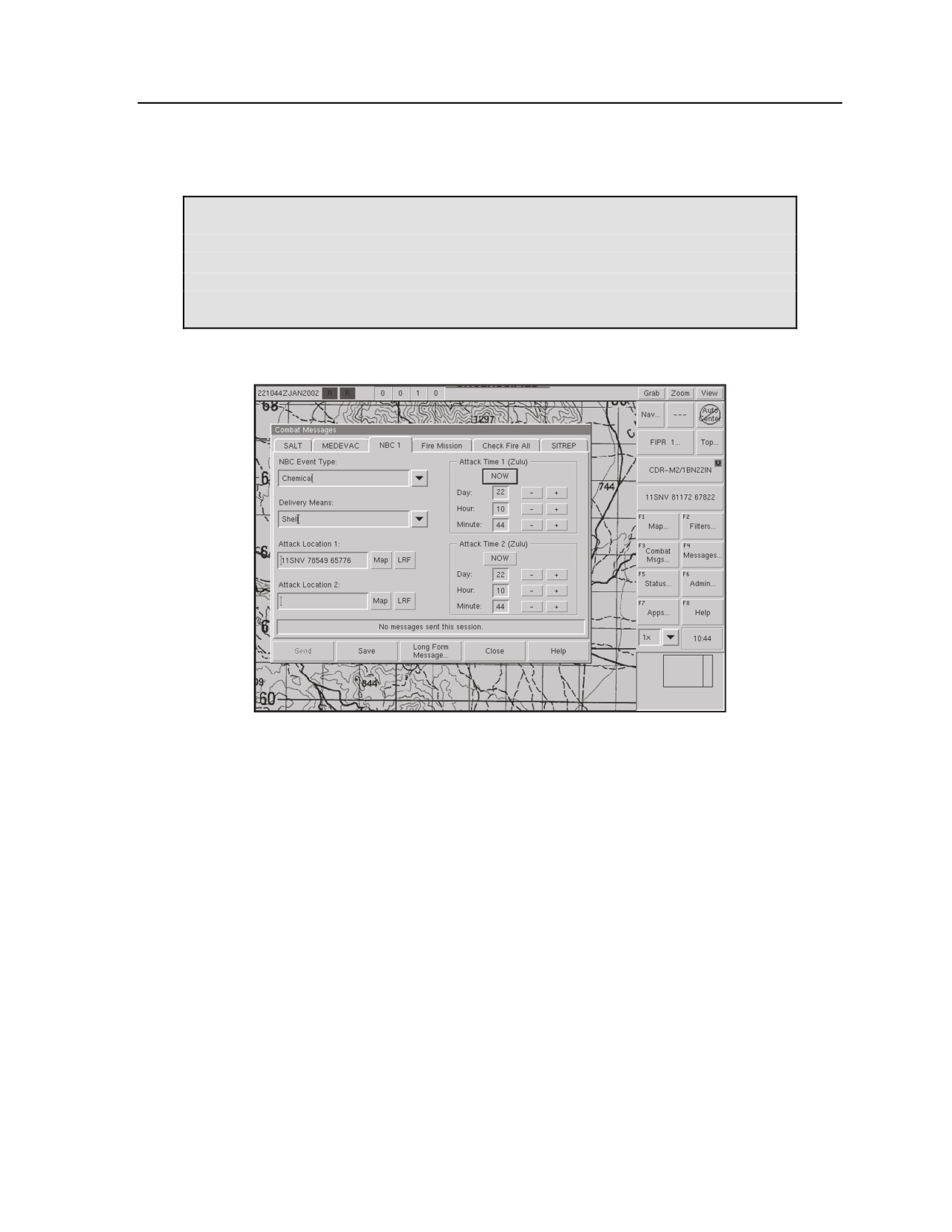
Note. The digital NBC-1 report (see Figure A-22) is sent on confirmation of contact with
CBRN weapons. The report is sent to the entire troop
NBC-1 - Observer’s Initial Report
Format
A-78. To send this report, state “NBC ONE” and give the type of NBC incident (nuclear, biological, or
chemical). Other information that may be sent includes precedence of the report, date and time of the
report (ZULU time), and security classification with "from" and "to" times the classification is applicable.
Provide all pertinent information on the following lines:
z
Line ALPHA: Strike serial number (if known).
z
Line BRAVO: Position of observer, using universal transverse Mercator (UTM) coordinates or
name of place.
z
Line CHARLIE: Grid or magnetic bearing (specify which is used) or azimuth of attack from
observer (in degrees or mils; specify which is used).
z
Line DELTA: DTG attack started (ZULU).
z
Line ECHO: Illumination time in seconds (for nuclear burst); time the attack ended (toxic agent
attack only).
z
Line FOXTROT: Location of attack (UTM coordinates) and/or vicinity of attack (actual or
estimated; specify which is given).
z
Line GOLF: Means of delivery (if known).
z
Line HOTEL: Type of burst (air, surface, unknown), type of toxic agent, or type of attack.
z
Line INDIA: Number of shells; other data (for toxic attack only).
z
Line JULIET: Flash-to-bang time (in seconds).
z
Line KILO: Crater present or absent; diameter in meters (if known).
z
Line LIMA: Cloud width (degrees or mils; specify which) 5 minutes after burst.
z
Line MIKE: Cloud height (top or bottom; specify which) 10 minutes after burst (degrees or
mils; specify which).
z
Line SIERRA: DTG of reading (local or ZULU time).
Note. DO NOT DELAY REPORTS in an attempt to provide complete format information.
Omit information that is not applicable or available. Items that must always be reported are the
type of report; lines D and H; and one of the following lines: B, C, F, or G.
Note. Carefully specify the units of measure used (such as degrees, mils, or grid azimuth).
A-30
FM 3-20.98
3 August 2009
Orders and Reports
Examples
A-79. Figure A-21 shows examples of NBC-1 reports for nuclear and chemical incidents. Figure A-22
shows an example of a digital report.
“THIS IS RED 1. NBC-1, NUCLEAR. LINE BRAVO: I SET DX, lMNUWS. LINE
DELTA:
020945 ROMEO. LINE HOTEL: AIR. LINE LIMA:
100 MILS,
ESTIMATED.”
“THIS IS RED 1. NBC-1, CHEMICAL. LINE DELTA:
261003 ROMEO. LINE
FOXTROT: NB783089. LINE GOLF: ARTILLERY. LINE HOTEL: VAPOR.”
Figure A-21. Sample NBC-1 reports for nuclear and chemical incidents
Figure A-22. Digital NBC-1 report (observer’s initial report)
NBC-3 - Immediate Warning of Expected Contamination
A-80. This report is sent by radio. State "NBC THREE," followed by pertinent information on these lines:
z
Line ALPHA: Strike serial number (if known).
z
Line DELTA: DTG when attack started.
z
Line FOXTROT: Location of attack (actual or estimated; specify which).
z
Line PAPA: Area of expected contamination.
z
Line YANKEE: Bearing or azimuth of left, then right radial lines (specify degrees or mils; use
4 digits for each line).
z
Line ZULU: Effective downwind speed (in kmph; use 3 digits), downwind effective distance of
zone (in km; use 3 digits), and cloud radius (in km; use 2 digits).
NBC-4 - Report of Radiation Dose-Rate Measurement
When Used
A-81. The NBC-4 report, used for nuclear activity only, is submitted immediately after any radiation is
detected and thereafter as required by the OPORD.
3 August 2009
FM 3-20.98
A-31
Appendix A
Format
A-82. To send this report, state "NBC FOUR," followed by pertinent information on these lines:
z
Line QUEBEC: Location of reading; use friendly graphics or encryption. Omit this line when
transmitting on a wire net.
z
Line ROMEO: Dose rate in cGy/hr (average total dose rounded to the nearest 10 cGy). Specify
whether the dose rate is "INITIAL," "INCREASING," "PEAK," or "DECREASING"; specify
"SHIELDED" if the dose rate was measured inside a vehicle.
z
Line SIERRA: DTG of reading. Specify the time zone.
Note. Repeat lines Q, R, and S as often as necessary. Radiation dose rates ideally are measured
in the open, one meter above the ground; if the rate must be measured in a shielded location, it is
converted (as accurately as possible) to a rate in the open.
Examples
A-83. Figure A-23 shows examples of NBC-4 radiation dose-rate measurement reports.
“THIS IS RED 1. NBC FOUR. LINE QUEBEC: LB 123987. LINE ROMEO:
1,
INITIAL. LINE SIERRA: 201735 LOCAL.”
“THIS IS RED 1. NBC FOUR. LINE QUEBEC: LB 123987. LINE ROMEO:
60,
PEAK. LINE SIERRA: 201805 LOCAL.”
Figure A-23. Sample NBC-4 radiation dose-rate measurement reports
Note. Users of NBC-4 reports are not confined solely to the use of the letter items shown in
these examples.
NBC-5 - Report of Areas of Contamination
A-84. To send this report, state “NBC FIVE.” Other information that may be sent includes precedence of
the report, date and time of the report (ZULU), and security classification with “from” and “to” times the
classification is applicable. Provide all pertinent information on the following lines:
z
Line ALPHA: Strike serial number, if known.
z
Line OSCAR: Reference DTG for estimated contours of contaminated areas.
z
Line SIERRA: DTG when contamination was initially detected.
z
Line TANGO: H+1 DTG or DTG of latest reconnaissance of contamination in the area.
z
Line UNIFORM: Coordinates of contour lines marking dose rate of 1,000 cGy/hr.
z
Line VICTOR: Coordinates of contour lines marking dose rate of 300 cGy/hr.
z
Line WHISKEY: Coordinates of contour lines marking dose rate of 100 cGy/hr.
z
Line X-RAY: Coordinates of contour lines marking dose rate of 20 cGy/hr.
A-32
FM 3-20.98
3 August 2009
Appendix B
Site Exploitation
Site exploitation
(SE) is a series of related activities and actions initiated and
conducted by Army forces in cooperation with joint, interagency, intergovernmental,
multinational agencies and special operations forces
(SOF) for the purpose of
exploiting personnel, documents, electronic data, and materiel. The platoon conducts
SE to ensure that all scouts identify, collect, protect, and evaluate documents,
materiel, and personnel to facilitate follow-on actions. The importance of SE goes
beyond the concept that every Soldier is a sensor. The scout must understand the
significance of the objective area and his role in the potential availability of
information for collection and analysis. Whether at a traffic control point (TCP), in a
room during a search, or at a suspected factory for IEDs or EFPs, the
reconnaissance/scout platoon can expect to conduct SE at some level in every
mission it undertakes. One skill that plays an important part in gaining awareness and
collecting information about the site is tactical questioning (TQ). Every scout must
know how to use TQ to enhance awareness of the current situation. This personal
contact and the observations of individual Soldiers are critical elements in the
platoon’s ability to develop a comprehensive understanding of the OE. For additional
information, see FM
3-90.15 and Center for Army Lessons Learned
(CALL)
Handbook 07-26.
SECTION I - PURPOSE OF SITE EXPLOITATION
B-1. SE is the overarching concept that encompasses technical site exploitation, sensitive
site
exploitation, explosive ordinance disposal (EOD) site exploitation, evidence and criminal site exploitation,
and technical intelligence site exploitation. At the tactical level, the platoon integrates SE in its assigned
missions and identifies, evaluates, collects, and protects personnel, documents, electronic data, and other
material at a site.
B-2. SE covers the spectrum of exploitation activities, including the following:
z
DOMEX.
z
Equipment exploitation.
z
Hasty analysis of pocket trash.
z
Mirror imaging of media and expediting various forms of media to the rear for further
exploitation.
z
EOD site exploitation, which can include weapons inspection teams (WIT) conducting blast
analysis.
z
Criminal site exploitation, which may incorporate support from HN, Central Intelligence
Agency (CIA), Federal Bureau of Investigation (FBI), and other governmental agencies.
B-3. Regardless of the size, echelon, and composition of the exploitation element, SE fundamentally
serves three basic purposes:
z
Answer IR.
z
Facilitate subsequent operations (through intelligence analysis and targeting).
z
Facilitate criminal prosecution by HN authorities.
3 August 2009
FM 3-20.98
B-1
Appendix B
ANSWER INFORMATION REQUIREMENTS
B-4. SE can be used to answer some commander’s critical information requirements (CCIR) through a
range of tools, including TQ and DOMEX. Effective planning for patrols, cordon and searches, raids, and
other CI operations can yield information that will answer the squadron commander’s CCIR. In addition,
proper SE can protect valuable information that, when properly collected and analyzed, can answer CCIR
or priority intelligence requirements (PIR) for the squadron or higher headquarters. Examples of CCIR/PIR
that could be answered by SE include the following:
z
Who are the key town council, tribal, or religious leaders in the area of operations (AO)?
z
What are the perceptions of these key community leaders?
z
How do these key leaders make their decisions, and how can those decisions be influenced?
z
What hostile elements are present in the AO? Who determines whether elements are to be
considered hostile or noncombatants?
z
What political, cultural, and religious sensitivities will have an impact on the noncombatants?
z
Who or what are the key information providers in the AO?
z
What effort is the enemy making to influence the target audiences?
z
What tools are they using (radio, television [TV], leaflets, disinformation, intimidation)?
z
Who are the enemy’s supporters, and what are their actions?
z
What nongovernmental/international organizations are operating in the AO?
z
Who are their key personnel?
z
Are there any enemy-affiliated religious sites in the AO?
z
Where are enemy safe havens/safe houses in the AO?
z
Are there enemy weapons caches within the AO?
z
Are there any weapons markets in the AO?
z
What infrastructure needs to be repaired in the AO?
B-5.
Additionally, effective SE can provide information that may answer other IR, such as—
z
Where are HN security forces operating in the AO?
z
How are HN security forces reacting to enemy activity in the AO?
z
How are HN security forces reacting to coalition activity in the AO?
z
What are the significant characteristics of enemy units in the AO?
z
What enemy cells are operating in the AO?
z
Who are the enemy leaders in the AO?
z
What are the local priorities for infrastructure repair in the AO?
z
What rivalries exist between leadership in the AO?
z
Where are all the crossing points (foot and vehicle) for the canals in the AO?
z
Is the indigenous police force corrupt?
z
How is the HN police force received by the community?
z
Can the HN police force be relied upon as an asset to assist U.S. and joint forces?
z
If the HN police force is reliable, what equipment, communications, and other capabilities does
it have?
FACILITATE SUBSEQUENT OPERATIONS
B-6. Effective SE provides critical data for inclusion in the intelligence process, which in turn supports
targeting and other aspects of subsequent operations. This can encompass the collection of information and
material within a building or on the terrain, as well as TQ of personnel located on the objective. In
conducting SE, the reconnaissance/scout platoon initially identifies material and personnel of interest. It
then collects these items and personnel and conducts debriefing with the squadron/battalion S2 after the
operation is completed. The collected material is processed and analyzed, and the appropriate agencies
further interrogate the personnel.
B-2
FM 3-20.98
3 August 2009
Site Exploitation
An example of SE leading to follow-on missions
Situation:
During clearing operations in Adhamiyah, 1-14 Cavalry entered empty apartments
and found suspicious items. The unit called for the squadron QRF/SE team to
investigate. The SE team arrived and conducted a thorough exploitation of two
apartments after EOD confirmed there were no IED/EFP threats. SE resulted in
numerous finds indicating the site was used by an advanced IED component maker.
Items discovered include IED components, manuals outlining electrical engineering,
surveillance instructions, IED-making documents, personal identification documents,
modified cell and long-range cordless phones, initiators ready-made to plug into
explosive devices, MBITR-type radios, radio control parts, empty cell phone boxes
with serial numbers, and oscilloscope and circuit testing kits. The materials were
recovered in accordance with SE protocols and were sent to the combined
explosives exploitation cell (CEXC) for analysis.
Initial CEXC assessment:
This cache yielded at least one initiator ready for use in an IED, as well as hundreds of
components for other radio-controlled IEDs. Extensive bomb-making literature was
recovered from the site. The IED-related material and literature indicated an individual
with significant knowledge, ability, and resources may still be in the Baghdad area.
Initial actionable information:
According to a quick translation by DOMEX on-site, a paper was found to read—
To: Al-Madi Sadee
For Electronic Manufacturing
Enclosed part numbers 64, 87, 35, & 16
Assemble at 1217 Dandi Street
Near Al-Assad University
Phone 415-1174
The DOMEX translator linked this document with several others from the site and
determined the location belonged to the same individual who resided/worked at the
site. Subsequently the target was identified based on the SE and a follow-on mission
captured the suspect.
FACILITATE CRIMINAL PROSECUTION
B-7. Collection of material associated with criminal/insurgent activity, to be handed over to
local
government agencies for prosecution, is often critical to the success of operational and strategic Army
objectives. This is especially true in stability operations, which frequently support attempts to establish
local governance and control.
SECTION II - SITE EXPLOITATION PLANNING AND ORGANIZATION
B-8. SE is associated with all missions, including cordon and search, raids, patrols, traffic control points
(TCP), and attacks. All of these missions encompass the requirement to plan and conduct SE at various
levels of detail, from individual Soldier actions to multifaceted and specialized task organized teams.
B-9. SE will generally be an “on-order” or a “be prepared” mission associated with the specified/essential
task that defines the primary mission. SE can appear as a specified task in the order; however, at a
minimum, it will be included as an implied task for planning in all missions. In a counterinsurgency
environment, where IEDs/EFPs are a weapon of choice, SE can become an essential task for the
commander. The following is an example of how SE relates to another mission:
1-14 Cavalry conducts a cordon and search of OBJ BAT NLT 120900ZJAN07 to
capture/kill ACF and limit the attacks on coalition forces. On order, conduct site
exploitation of OBJ BAT to collect information for the intelligence process.
3 August 2009
FM 3-20.98
B-3
Appendix B
PLANNING FACTORS
B-10. Units complete SE planning at the level of detail allowed by time constraints and enemy/threat
considerations. In analysis of the higher headquarters order in terms of SE, the tenets of mission analysis
remain the same, but special focus on key areas such as tasks, augmentation, equipment, available
collection assets, timelines, risk analysis, and the human dimension of the AO will affect the commander’s
planning effort. Understanding the higher commander’s intent is still critical to the process. Additionally,
mission analysis should consider the task of collecting biometric data.
AUGMENTATION
B-11. The reconnaissance/scout platoon does not possess the organic assets to complete many of the
detailed requirements of complex SE. Attachments from EOD, MI, and MP units, together with specialized
assets such as military working dogs (MWD) and WITs, may be required based on the staff’s estimate.
Internally, the staff must identify subordinate units that can fulfill these roles while understanding their
organic capabilities and limitations.
EQUIPMENT
B-12. Figure B-1 provides a recommended supply and equipment list for SE operations.
Megaphone with extra batteries
Metal detectors/wands
Breach equipment (hooligan tools, etc.)
Mine detectors
Bolt cutters
Mirrors
Ladders
Creepers
Signs in applicable languages for checkpoints
Class IV materials (such as concertina wire)
Triage equipment (evidence collection kits)
Zip ties/flex cuffs
Improvised equipment (trash bags, MRE
Video cameras, still cameras, tape
boxes, pillow cases, flour bags)
recorders
Fingerprint kits
Flashlights with extra batteries
GPS
IO products
3-4 permanent markers
Prepackaged holding area supplies
30 zipper-lock plastic bags
Computer and related materials
20 shoe tags
Gunpowder residue kit
Sim card reader
Dry erase board
Suitcases
Flashlight / head lamp
Blindfolds
Protective rubber gloves
3 extra backpacks
Figure B-1. SE supplies and equipment
BIOMETRIC COLLECTION ASSETS
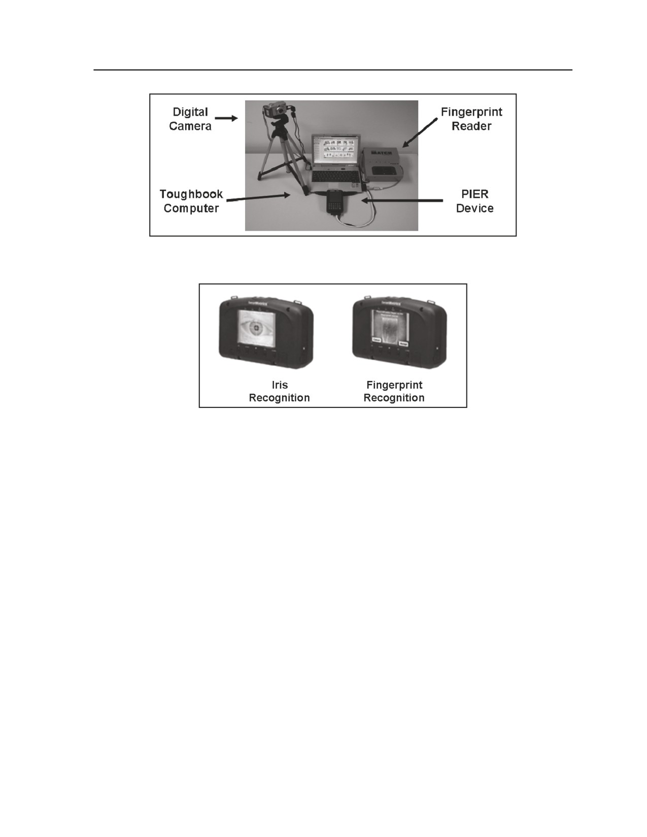
B-13. Biometrics refers to the use of a person’s physical characteristics or personal traits to identify or
verify the claimed identity of, that individual. Fingerprint minutia, iris pigmentation, facial geometry, voice
analysis, and handwritten signatures are examples of characteristics used to identify an individual.
Electronic, automated biometrics-based systems (biometric systems) provide a means of converting these
relatively unique individual attributes from a biometric characteristic—a fingerprint, for example—into
digital form. The results can then be compared against a computerized database to establish identity
quickly and relatively accurately. See Figures B-2 and B-3.
B-4
FM 3-20.98
3 August 2009
Site Exploitation
Figure B-2. Typical biometrics automated toolset
Figure B-3. Typical HIIDE displays
RISK ANALYSIS
B-14. To mitigate risks for the exploitation team, the commander evaluates the risks inherent to the SE
environment. This entails such considerations as ensuring the site has been properly secured and evaluating
the ability to clear IED/EFP threats prior to exploiting the site.
TIMELINES
B-15. The timeline will affect the platoon when internal forces have multiple tasks that require a transition
to SE. Additionally, the timeline will be evaluated to consider the impact of higher headquarters assets that
can be requested/directed to assist in SE once the platoon identifies that the level of material, personnel,
buildings, or terrain at the site exceeds the assigned or organic collection capabilities.
ADDITIONAL CONSIDERATIONS
B-16. In addition to the ROE, which will guide SE planning and to which the platoon will always adhere,
other planning considerations include the following:
z
Tactical call out. This affects forces clearing the objective, especially those that may have an
initial inability to connect called out personnel with their locations on the objective.
z
EOF. Escalation will require a balance between force protection, protection of noncombatants,
and efforts to prevent collateral damage that may have a negative impact on operational and
strategic objectives.
z
Language barriers. Language differences, or a lack of interpreters, can make it difficult for
Soldiers to interpret the actions of personnel on the objective/site.
z
Time factors. The projected time available on the objective to conduct SE must be considered.
3 August 2009
FM 3-20.98
B-5

Appendix B
ORGANIZATION
B-17. Regardless of the size of the element conducting the exploitation, an SE team leader is responsible
for planning, organizing, equipping, and executing the SE. If available or required, an assistant SE team
leader will be assigned to support the team leader in completion of SE. Subordinate to the team leader will
be a minimum of two elements, one for conducting TQ and another for conducting the search. The size and
scope of these elements, along with the establishment of additional elements
(such as detainee,
documentation, field interview, demolitions, and tunnel reconnaissance teams), will vary with METT-TC
considerations.
B-18. SE is not necessarily restricted to large-scale operations. For example, hasty SE can occur at a TCP
with the approach of a single vehicle. An initial search may indicate that SE is required for the vehicle and
its occupants. Once conditions of the search have transitioned from controlling access and deterring illegal
activity to a hasty exploitation of the “site,” the principles of SE will apply. Search personnel will initiate
exploitation to the level of assets available, and request assistance if the exploitation exceeds capabilities.
B-19. The commander may task the reconnaissance/scout platoon leader to organize to conduct troop-level
SE. The platoon can task organize as the TQ element or search element. Figure B-4 summarizes duties and
responsibilities for SE personnel. The TQ element typically includes—
z
Platoon leader.
z
Questioning team.
z
MP.
z
Category (CAT) II interpreter.
B-20. The search element typically includes—
z
Platoon leader.
z
Search team.
z
MWD.
z
EOD.
z
WIT.
z
CAT I interpreter.
SE Team Leader:
z
Command SE team
z
Initiate and control SE
z
Complete initial sketch of site
z
Document all activity
z
Deconflict/validate information with each element
z
Report and recommend action on immediate intelligence to commander
z
Supervise collection of all personnel and material
z
Ensure detainees are photographed with evidence of illegal activity
SE Search Element:
z
Conduct detailed search of target according to plan
z
Ensure IED awareness
z
Identify and process evidence
z
Recover evidence
z
Prepare evidence for transportation
z
Document evidence recovery
SE Tactical Questioning Element:
z
Identify/prioritize subjects for TQ
z
Coordinate security for collected personnel
z
Separate personnel as required for questioning
z
Conduct TQ
z
Identify/prioritize subjects for removal/detention
z
Document all TQ
Figure B-4. Summary of duties and responsibilities for SE personnel
B-6
FM 3-20.98
3 August 2009
Site Exploitation
SUPPORTING ASSETS
B-21. A number of assets may be attached, OPCON, or in DS of the squadron/troop and platoon when
conducting missions that encompass SE. These assets include the following:
z
Joint document and media exploitation center. The joint DOMEX center serves as the
collection point for all enemy documents overtly recovered during the SE. It also performs in-
theater screening and exploitation of those documents in support of intelligence agency
requirements at the theater, geographical combatant commander, and national/coalition levels.
The typical DOMEX section that may support the BCT or division collection effort consists of
five linguists, normally CAT II or III, and an additional linguist for forward support.
Additionally, a medical exploitation section, with a forensic analyst and one linguist, may be
available. (See FM 3-31 for further details.)
z
Linguists (interpreters). Leaders base assignment of linguists to subordinate elements on
availability, as well as the category
(CAT) status of available linguists. Linguists are
categorized based on background, capability, and security level as follows:
CAT I. CAT I linguists are locally hired personnel with an understanding of the English
language. Sensitivity of the potential exploitation site may limit the use of CAT I linguists.
CAT II. CAT II linguists are U.S. citizens who have native command of the target
language and near-native command of the English language.
CAT III. CAT III linguists are U.S. citizens who have native command of both the target
language and English.
z
Civil affairs team. CA Soldiers collect information and conduct assessments to help friendly
forces target their relief efforts or stabilize the civil environment. CA teams should be
incorporated with the information operations (IO) process to meet operational objectives, assess
the environment, and evaluate the effect of search operations on the region. CA teams can meet
with local leaders to outline the goals and objectives of the operation.
z
Weapons inspection team (WIT). WITs include personnel with specialized skills to analyze
IED sites and material located on the objective that can be tied to IED development. Their
capabilities include IED detection, post-blast analysis, and IED defeat capabilities.
z
Combined explosives exploitation cell (CEXC). The CEXC is a joint agency tasked with the
collection and exploitation of IEDs. It provides immediate in-theater technical and operational
analysis, including identification of enemy tactics and trends (see FMI 3-34.119 for more details).
z
Military police (MP). MP support can take various forms in SE:
Platoon-size MP element to assist with security, detainee collection, and other support.
MP with search dogs.
MP investigators to assist with site evaluation and collection of forensic evidence.
z
Military investigators. Units and investigators from the Army Criminal Investigation Division
Command, Naval Criminal Investigative Service, and Air Force Office of Special Investigations
can assist in collection and processing of materials. Many of the units are equipped to support
collection of forensic evidence and can assist in biometric tasks.
z
Explosive ordnance disposal (EOD). EOD personnel may clear an identified explosive hazard
or assist in the collection of explosive components.
z
Psychological operations (PSYOP). PSYOP teams can support the platoon during search
operations by coordinating public broadcast of information, using loudspeakers or other delivery
means, to influence the population on or near the objective. The platoon leader should consider
withdrawing from the area when employing PSYOP capabilities. At the tactical level, PSYOP
teams seek to influence targets directly through face-to-face contact, limited production of
printed products, and use of loudspeakers. Tactical PSYOP can—
Influence potential adversaries in the civil population not to interfere with friendly forces.
Induce cooperation or reduce active opposition.
Reduce collateral damage by giving instructions to noncombatants in the combat zone.
3 August 2009
FM 3-20.98
B-7
Appendix B
z
Aviation. Reconnaissance and attack aviation assets, particularly rotary wing assets, can
provide additional security en route to and from the objective, assist in isolation of the objective
site, and provide overwatch of high-value individuals attempting to flee the objective.
z
Other governmental agencies. Based on the scope of the operation and the suspected material
or personnel on the objective, agencies such as the FBI and CIA may take part in the SE effort.
SECTION III - SITE EXPLOITATION EXECUTION
ACTIONS ON THE OBJECTIVE
B-22. The execution of SE normally occurs after an objective has been seized, cleared, or otherwise
controlled to the point at which the exploitation team can conduct the search to the level of detail required
with appropriate risk mitigation. In the case of a cordon and search operation, this may mean after the
objective location has been isolated and secured and the IED/EFP threat on the objective mitigated by EOD
or search dog support, if available. At a minimum, the SE team will understand the level of threat
remaining on the site prior to exploitation. The SE team leader will conduct an initial debrief of the assault
force (initial entry force) and will then assess the site to make a determination of the scope and breadth of
the exploitation required.
B-23. Upon completion of the initial assessment, the team leader updates instructions to the search teams,
takes and/or directs initial photographic evidence of the site, completes a sketch of the objective site, and
coordinates marking of the objective for documentation purposes. The TQ element(s) will coordinate with
the search element to segregate personnel found on the objective in secure areas, noting where personnel
were located based on the team leader’s site sketch.
B-24. Search teams initiate the search of the site/objective using a defined pattern and collection process
according to unit SOPs. The team leader must have the ability to move throughout the site and coordinate
with the TQ and search teams. The team leader can focus search efforts based on the information gained by
TQ, as well as guide the TQ team based on the items that are uncovered during the search. This is a useful
tool in identifying additional information and in determining whether suspected personnel are attempting to
deceive the TQ team. METT-TC considerations may facilitate the use of the head of household to
accompany the search team, which can alleviate the perception of destruction of property and mitigate the
risks of IED/EFP attack. On the other hand, this technique can impose limitations on the search team, such
as possibly influencing decisions concerning which items/personnel are valuable to the SE effort and which
are not.
B-25. Collection of material will be completed with appropriate marking/tagging in accordance with SOP
and theater requirements. During the collection, the SE element will observe any special considerations for
handling of material that can be exploited for forensic evidence; it will also watch for evidence that could
be associated with detonation devices. Material that can be used as evidence in judiciary proceedings will
be photographed with the suspected individual. Maintaining control and custody of collected material is
critical for the SE element in maintaining the integrity of the search.
CONSOLIDATION AND REORGANIZATION
B-26. The SE team establishes detainee collection points, casualty collection points (CCP), and captured
material collection points and ensures that all collection sites are appropriately marked and secured. The
support element in a cordon and search or raid assists in these tasks. PSYOP and CA teams can also assist
in crowd control while searching the objective and preparing for withdrawal.
B-27. Once the search is complete, leaders ensure all collected items and personnel are properly
documented, photographed, and handled according to SOP to ensure proper accountability and chain of
custody.
WITHDRAWAL
B-28. Planning for additional security during retrograde operations may be required based on what the SE
has uncovered. Additionally, if the site requires exploitation beyond the platoon’s capabilities and time
B-8
FM 3-20.98
3 August 2009
Site Exploitation
available, the platoon may have to leave a force behind to maintain security for follow-on exploitation
teams. Leaders evacuate detainees with basic subsistence items.
B-29. After the unit conducts retrograde back to the FOB or patrol base, it must conduct an effective
debrief with the squadron S2. All collected evidence, material, and personnel will be reviewed with the S2
or processing agency. Detainees will be processed immediately at appropriate detainee collection points
(squadron/BCT/division); this includes making database entries into BAT. The squadron judge advocate
can assist the S2 in the debriefing and will coordinate and document material for HN prosecution.
INTELLIGENCE SUPPORT
B-30. The squadron and/or higher headquarters will evaluate the collected material and detained personnel
for information that can facilitate the planning of future operations. In addition, all material and
personnel—the information gained from them— is incorporated into an intelligence database for continued
pattern and link analysis. Trained interrogation teams can attempt to exploit detainees for further
information at approved holding areas. Exploitation of the information can provide intelligence that will
assist in follow-on targeting. The squadron/BCT staff will follow up with supporting agencies for
information exploited from tactical operations.
SECTION IV - TACTICAL QUESTIONING
B-31. Small units and individual Soldiers collect information and contribute to overall awareness of the
current situation in almost any action that involves observing and reporting elements of the OE and
activities of people in the AO. They serve as the commander’s “eyes and ears” in a variety of tactical
situations:
z
Performing traditional offensive or defensive missions.
z
Performing a patrol in stability operations, with patrol reporting cueing collection by a tactical
human intelligence team.
z
Manning a traffic control point (TCP).
z
Οccupying an OP.
z
Handling EPWs and detainees, along with captured enemy documents and captured enemy
equipment.
z
Passing through areas in convoys.
B-32. TQ is expedient initial questioning conducted to gain information of immediate value. When the
term applies to the interaction with the local populace, it does not usually take the form of formal
questioning; rather, it refers to personal contact that is more conversational in nature. The task of TQ can
be designed to build rapport as much as to collect information and understand the OE.
B-33. Soldiers conduct TQ based on the platoon and troop’s SOPs and the order for that mission. Small-
unit leaders include specific guidance for TQ in the OPORD for appropriate missions. Information that the
Soldier reports as a result of TQ is passed up the chain of command, in many cases to the S-2 at the
squadron or BCT, where it can become a vital part of planning and operations.
COLLECTING INFORMATION
B-34. Information collection occurs at all times during operations. Collection of combat information
consists of becoming familiar with the surrounding environment, to include the people, infrastructure, and
terrain, as well as recognizing change. Like a police officer “walking the beat” in a neighborhood day after
day, Soldiers at all ranks and echelons must be able to recognize that something has changed and, if
possible, to understand why. Even if the Soldier cannot determine why something changed, simply
reporting that there has been a change can help MI personnel. Scouts should train themselves to become
constantly aware of conditions such as⎯
z
Armed elements. Location of factional forces, minefields, and potential threat/enemy elements.
z
Homes, buildings, and other personal property. Condition of roofs, doors, windows, lights;
presence of vehicles, outbuildings, crops, and livestock.
3 August 2009
FM 3-20.98
B-9
Appendix B
z
Infrastructure. Presence of functioning stores, service stations, and open air markets; condition
of public areas and resources, such as roads, bridges, and power lines; availability of public
utilities (water, electricity, sanitation) through regular delivery means.
z
People. Numbers, sex, and age; visible health; clothing; daily activities; leaders; residence or
displaced persons, refugees, or evacuees status.
z
Contrast. Has anything changed? For example, are there new locks on buildings? Are windows
boarded up or are previously boarded-up windows now open, indicating a change of use of a
building? Have buildings been defaced with graffiti?
B-35. Because every Soldier is involved in the collection of combat information, everyone must be aware
of the current, applicable IR. All Soldiers who have contact with the local populace, who routinely travel
within the area, or who frequently attend meetings with local organizations must know the commander’s
IR and understand their responsibility to observe and report.
KEY CONSIDERATIONS FOR CONVERSATIONS
B-36. Certain vital elements of communication can make a conversation more effective and productive.
Every AO will have specific social and regional considerations that can affect communication and in turn
have an impact on the conduct of operations. These may include social taboos, desired behaviors, customs,
and courtesies. The commander includes this information in predeployment training at all levels to ensure
that Soldiers are properly equipped to interact with the local populace. Soldiers must also keep in mind
safety considerations and possible dangers associated with their actions.
B-37. Guidelines for Soldiers in establishing effective communication while ensuring personal safety
include the following:
z
Know the threat level and force protection measures in the AO.
z
Know as much as possible about the local culture, including customs and courtesies (for
example, male Soldiers not speaking to women or female Soldiers not speaking to men).
z
Learn a few phrases in the local language.
z
Be careful of body language.
z
Approach people in normal surroundings to avoid suspicion.
z
Be friendly and polite.
z
Remove sunglasses when speaking to locals.
z
Ιf security conditions permit, keep weapons in the least intimidating position possible.
THE QUESTIONING PROCESS
B-38. Using questions is the best way to start and maintain a conversation. Try to use open questions that
cannot be answered simply “yes” or “no.” These are basic questions that normally begin with an
interrogative (who, what, where, when, how, or why) and require a narrative answer. They are brief and
simply worded to avoid confusion. Example: “When was the last time you saw suspicious activity here?” is
more useful than, “Have you seen insurgents in this area?” It is a better question because it requires a
narrative response and requests specific elements of information. In addition, locals may have a different
interpretation of “insurgent.”
QUESTION GUIDELINES
B-39. Well-crafted open questions have the following characteristics:
z
They are broad in nature and serve as an invitation to talk. They require an answer other than
“yes” or “no.”
z
They give the individual freedom in answering. Questions do not offer a forced choice such as,
“Was the man tall or short?” Not only could the answer to that question be confusing, but it also
does not allow for responses such as “average height,” “medium,” or other descriptions.
z
They encourage discussion. Let the person know that you are interested in his opinion or
observations.
B-10
FM 3-20.98
3 August 2009
Site Exploitation
z
They allow the questioner to listen and observe as the individual talks. While the person is
answering, carefully watch for signs of nervousness or other nonverbal communication.
z
They pose little or no threat to the individual. Not all questioning is targeted at information
collection. Asking questions about neutral or “safe” topics can help build rapport.
z
They allow people to become involved. People like to think that their opinion is important.
Asking what people think allows them to feel that they are involved.
z
They elicit answers that reveal what the person thinks is important. In relating their experiences,
people will often start with what is most important to them.
z
They create a conversational tone. For example, a simple question about family, work, or hobbies
allows a person to talk freely since the topic is nonthreatening and one that they know about. Such
impertinent questions can serve as a springboard to topics more closely related to the collection
requirement, often without the person you are talking to realizing that the topic has changed.
MAINTAINING THE CONVERSATION
B-40. Once a conversation is established, use some common techniques to keep it flowing:
z
Avoid use of military jargon, especially with civilians.
z
Be prepared to discuss personal interests (hobbies, books, travel).
z
Be sensitive of body language, but use it to your advantage whenever possible. Follow these
guidelines:
Smile as long as it is appropriate.
Avoid sitting with arms crossed.
Do not show the bottom of feet in an Arabic culture.
Keep your hands away from the mouth.
Lean forward and nod.
Make frequent eye contact (if culturally appropriate).
ADDITIONAL CONVERSATION TIPS
B-41. An important guideline in any conversation that involves TQ is to be subtle. Remember to be sociable,
yet reserved at all times. Rattling off a series of questions and writing down the responses will not gain the trust
of the individual with whom you are speaking. Other helpful considerations include the following:
z
Use the person’s name, position title, rank, and/or other verbal expressions of respect.
z
Avoid judging the person by age, gender, or appearance.
z
Keep body posture relaxed, but alert.
z
Remember—a person’s favorite topic is himself or herself.
z
Use humor carefully. Some cultures consider excessive humor to be offensive or a sign of
deceit.
z
Understand and take into account the significance of holidays and religious days or times of the
day or week.
z
Have a second person listen to the conversation and later compare what you heard for accuracy
of recall.
EXAMPLE QUESTIONS
B-42. The following basic list of example questions can be tailored to fit requirements for the local
populace and/or EPWs/detainees. These questions were originally created for conditions specific to TCPs
and roadblocks. Keep in mind that they are only examples; you may need to modify or add to them based
on the mission, unit guidance, and the specific situation.
z
What is your name? (Require verification with identification papers, and check any applicable
lists or rosters, such as “detain,” “of interest,” or “protect.”)
z
What is your home address? (Ask for a former residence from displaced persons.)
3 August 2009
FM 3-20.98
B-11
Appendix B
z
What is your occupation?
z
Where were you going? (Get specifics.)
z
Why are you going there? (Get specifics.)
z
What route did you travel to arrive here?
z
What obstacles (or hardships) did you encounter on your way here?
z
What unusual activity did you notice on your way here?
z
What route will you take to get to your final destination?
z
Whom do you (personally) know who actively opposes U.S. (or multinational) forces? Follow
this up with, “Who else?” If the person knows of anyone in this category, ask the nature of any
hostile activities (against U.S. or multinational forces), including when and where such activities
have occurred.
z
Why do you believe we (U.S. or multinational forces) are here?
z
What do you think of our (U.S. or multinational force) presence here?
B-43. Although these questions may seem broad, they are in fact pointed and specific. They do not leave room
for misinterpretation or afford the person being questioned the chance to give a vague or misleading answer.
B-44. Always keep questions pertinent to your mission and report the answers promptly according to unit
guidance. Information of critical tactical value does no good if it remains in one place or if it arrives after
the operation or the event.
POTENTIAL PROBLEMS IN QUESTIONING NONCOMBATANTS
B-45. In conducting TQ of noncombatants, it is imperative that all questioners follow the provisions of the
Geneva Conventions at all times (see FM 27-10). Do not mistreat noncombatants in any way.
B-46. In questioning noncombatants, DO NOT⎯
z
Attempt to force or scare information from them.
z
Attempt to recruit or task someone to seek out information.
z
Pay money or make other compensation for information.
z
Ask questions in an area where the questioning puts the noncombatant in danger. Be discreet,
but not so discreet that you attract attention.
z
Ask questions that make your unit’s mission or IR obvious.
z
Take notes in front of the person after asking questions.
z
Ask leading questions, which are generally constructed to elicit a “yes” or “no” answer rather
than a narrative answer. Leading questions allow the individual to answer with a response he or
she thinks you want to hear, not necessarily the facts. Example: “Is Group XYZ responsible?”
z
Ask negative questions, which contain a negative word in the question itself. Example: “Didn’t
you go to the warehouse?”
z
Ask compound questions, which consist of two questions asked at the same time. Example:
“Where were you going after work, and who were you to meet there?”
z
Ask vague questions that do not provide enough information for the person to understand
exactly what you are asking. They may be incomplete, general, or otherwise nonspecific and
create doubt in the source’s mind.
POTENTIAL PROBLEMS IN QUESTIONING EPWS AND DETAINEES
B-47. When conducting TQ of EPWs or detainees, it is imperative that the provisions of the Geneva
Conventions be followed at all times. Refer to the discussion in Chapter 6 for additional considerations in
handling EPWs/detainees.
B-48. In questioning EPWs or detainees, DO NOT⎯
z
Attempt to force or scare information out of them.
z
Mention that they may be interrogated later or try any other “scare tactic.”
z
Give them comfort items. They are not your guests.
B-12
FM 3-20.98
3 August 2009
Site Exploitation
z
Pay money or make other compensation for information.
z
Inform them of their rights; someone else will handle that task.
B-49. In questioning EPWs or detainees, DO—
z
Ask only basic questions as described earlier in this section.
z
Move detainees to a detention facility as quickly as possible.
WORKING WITH INTERPRETERS
B-50. The use of interpreters is an integral part of the information collection effort. Working with an
interpreter, however, can be time-consuming and potentially confusing. Proper use and control of an
interpreter is a skill that scouts must learn and practice to maximize the effectiveness of the collection.
B-51. Perhaps the most important guideline to remember is that an interpreter is essentially your
mouthpiece; he says what you say, but in a different language. This sounds simple, but for those who have
never worked with interpreters, problems can quickly develop.
B-52. Upon meeting your interpreter, it is important that you assess his or her proficiency in English. You
need an interpreter with a firm grasp of English and the terminology that can be encountered.
Categories of Interpreters
B-53. Interpreters are categorized as to their capability and the clearance they have been granted. The
categories below are more fully detailed in Interpreter Operations, Multiservice Reference Manual for
Interpreter Operations, February 2004. This manual can be obtained from the Air Land Sea Application
(ALSA) Center. Linguist categories (CAT I, II, and III) are summarized in the discussion in Section I of
this appendix covering supporting assets for SE.
Guidelines for Interpreters
B-54. The following discussion outlines tips that should prove useful when working with an interpreter.
Placement
B-55. Use these guidelines:
z
When standing, the interpreter should stand just behind the commander or element leader and to
the side.
z
When sitting, the interpreter should sit right beside the commander or element leader, but not
between him and the individual being questioned.
Body Language and Tone
B-56. Use these guidelines:
z
Have the interpreter translate the message using the same tone in which you are speaking.
z
Ensure the interpreter avoids making gestures.
Delivery
B-57. Use these guidelines:
z
Talk directly to the person with whom you are speaking, not to the interpreter.
z
Speak as you would in a normal conversation, not in the third person. For example, do not say,
"Tell him that…" Instead, say, "I understand that you…" and instruct the interpreter to translate
as such.
z
Speak clearly, avoid acronyms or slang, and break sentences uniformly to facilitate translation.
z
Some interpreters will begin to translate while you are still speaking. This is frustrating for some
people. If so, discuss your preference with the interpreter.
3 August 2009
FM 3-20.98
B-13
Appendix B
z
The most important principle to obey while using an interpreter is to remember that you control
the conversation, not the interpreter.
Security
B-58. Use these guidelines:
z
Work on the premise that the interpreter may at some point be debriefed by a threat intelligence
service.
z
Always assume the worst.
z
Avoid careless talk.
z
Avoid giving away operational and personal details.
z
Do not become emotionally involved.
Interpreter Checklist for Patrolling
B-59. Use these guidelines when an interpreter takes part in a patrol:
z
Tell the interpreter what you expect of him and how you want him to do it.
z
Tell the interpreter exactly what you want translated. The interpreter should translate all
conversation between you and the individual without adding anything on his own.
z
Just as questioning should be conducted in such a way as to disguise the true intent of the
questioning from the source, you should not reveal any type of IR—including friendly forces
information requirements (FFIR), priority intelligence requirements (PIR), or essential elements
of friendly information (EEFI)—to the interpreter.
z
Brief the interpreter on actions to take at the halt or in the event of enemy contact.
B-14
FM 3-20.98
3 August 2009
Appendix C
Urban Operations
Operations in urban terrain challenge leaders with a combination of difficulties rarely
found in nonurban environments. The distinct characteristics of an urban
environment multiplies the amount of cover and concealment combatants and
noncombatants may use. The complexity of urban geography stems from the man-
made environment set into varying natural terrain, from villages in wooded
countrysides to cities established in the desert. This appendix provides information
that is essential for the reconnaissance or scout platoon in adapting to reconnaissance
and security missions in an urban area.
SECTION I - INTRODUCTION
C-1. Urban terrain is complex terrain that will affect operations differently in each situation. A tactical
technique effective in one area may be effective for only short periods—or not at all—in another area.
Similarly, a policy popular with one urban group may cause resentment and hostility in another due to
diverse cultural differences. A variety of potential difficulties exist for forces operating in the urban area—
from conventional military forces and politically oriented insurgents, from a populace facing disease and
starvation, from local leaders and pervasive media complicating the situation. Platoon leaders, PSGs, and
their subordinate leaders must make extraordinary efforts to assess and understand their particular urban
environment. See FM 3-20.971, FM 3-06, and FM 3-06.11 for additional information.
FUNDAMENTALS OF URBAN OPERATIONS
C-2. When planning and executing urban operations, scouts consider certain fundamentals particular to
man-made complex terrain. The eight fundamentals of urban operations include—
z
Conduct aggressive ISR operations.
z
Understand the human dimension.
z
Separate noncombatants from combatants.
z
Avoid the attrition approach.
z
Control what is essential.
z
Maximize effects without unnecessary collateral damage.
z
Conduct close combat.
z
Conduct transition control.
C-3. See FM 3-20.971 for an explanation of each of the eight fundamentals of urban operations.
URBAN TERRAIN
C-4. Although each OE encountered by the reconnaissance or scout platoon has its own distinct
characteristics, urban areas are the most complex. The two primary factors that influence the complexity of
urban operations are—
z
Man-made terrain and supporting infrastructure.
z
The density of noncombatants in close proximity to combat forces.
3 August 2009
FM 3-20.98
C-1
Appendix C
C-5. Of these two key urban factors, noncombatants and the human dimension are the most important
and, potentially, the most confusing to scout units. Furthermore, man-made features significantly affect
military systems and units, and thus tactics and operations. Reconnaissance and scout platoons must
operate in three physical aspects of the city:
z
Airspace over the city.
z
Supersurface areas, such as buildings.
z
Subsurface and subterranean areas, such as sewers and subways.
PREPARING FOR URBAN OPERATIONS
C-6. To operate effectively in an urban environment, platoons must prepare by developing a thorough
understanding of the urban environment through rigorous, realistic training. Platoons cover full spectrum
operations, including appropriate TTP (see FM 3-06.11). In addition, preparations should cover—
z
Psychological impact of intense, close combat against well-trained, relentless, and adaptive
enemies.
z
The effects of noncombatants—including governmental and nongovernmental organizations and
agencies—in close proximity to Army forces.
z
An in-depth understanding of culture and its effects on perceptions.
z
An understanding of civil administration and governance.
z
The ability to mediate and negotiate with civilians, including effective communication through
an interpreter.
z
The development and use of flexible, effective, and understandable ROE.
z
Employment of a complex intelligence environment requiring lower-echelon units to collect and
forward essential information to higher echelons for rapid synthesis into timely and actionable
intelligence for all levels of command.
z
The communications challenges imposed by the environment as well as the need to transmit
large volumes of information and data.
z
The sustainment challenges associated with operations in an urban area, including constant
enemy operations against LOCs and sustainment bases.
TRAINING SOLDIERS FOR URBAN OPERATIONS
C-7. While reconnaissance and scout platoons need to retain freedom of maneuver and avoid becoming
decisively engaged with the enemy, they must be committed and prepared to close with and destroy enemy
forces in an urban environment if necessary. The only exceptions are the HBCT and ACR platoons (CFV),
which are equipped to decisively engage the enemy (if necessary, until the larger elements arrive to take
over the fight). Every scout must also be prepared to effectively interact with the urban area’s
noncombatant population and assist in his unit’s intelligence collection efforts. Each urban operation will
be unique, and platoon leaders need to conduct an analysis of the tasks requiring emphasis or modification
to match the conditions of the OE. In urban operations, every scout will likely be required to—
z
Perform advanced rifle marksmanship, including advanced firing positions, short-range
marksmanship, and night firing techniques (unassisted and with the use of optics).
z
Operate crew-served weapons.
z
Conduct reconnaissance of urban areas and combat patrolling.
z
Enter and clear buildings and rooms as part of an urban attack, raid, or cordon and search
operation.
z
Defend an urban area.
z
Act as a member of a convoy (including specific driver training).
z
Control civil disturbances.
z
Navigate in an urban area.
z
Determine if EOF is required.
C-2
FM 3-20.98
3 August 2009
Urban Operations
C-8. Other critical individual and collective urban operations tasks might include but are not limited to—
z
Conduct troop-leading procedures.
z
React to contact (ambush, snipers, indirect fire, and IEDs).
z
Establish an OP, personnel or vehicle checkpoint, or roadblock.
z
Support SE and cordon and search.
z
Secure a disabled vehicle or downed aircraft (including UAS).
z
Call for indirect fire, CAS, and CCA support.
z
Create and employ explosive charges.
z
Process detainees and EPWs.
z
Treat and evacuate casualties.
z
Report information accurately.
z
Understand the society and culture specific to the AO.
z
Use basic commands and phrases in the region’s dominant language.
z
Conduct TQ.
z
Interact with the media.
z
Conduct thorough after-action reviews (AAR).
VEHICLE CAPABILITIES AND LIMITATIONS
C-9. Reconnaissance and scout platoons are found in a wide range of parent units (IBCT, SBCT, HBCT, and
ACR). Scouts may be assigned in any of these units; reassignments in theater may require them to use
unfamiliar platforms. Scouts should have a working knowledge of each platform in terms of conducting
effective operations and fighting for information if necessary. Refer to FM 3-20.971 for details on vehicle
capabilities and limitations.
COMMUNICATIONS
C-10. The reconnaissance or scout platoon leader must plan for effective communications in the urban
environment. The effects of buildings, power lines, and civilian communications systems will create the
need for redundant communications in controlling the platoon’s freedom of movement.
C-11. Urban terrain affects LOS communications. For example, man-made structures interfere with radios
by absorbing or reflecting transmitted signals. Leaders mitigate this effect on LOS communications by—
z
Requesting a retransmission (retrans) site on supporting terrain or structures.
z
Repositioning C2 vehicles to maintain communications with all elements.
z
Requesting UAS retrans.
z
Tapping into existing antennas and retransmission stations.
HELICOPTER SUPPORT
C-12. The reconnaissance/scout platoon may request attack reconnaissance helicopter support, utility
helicopter support, and UAS support. See FM 3-20.971 for information on missions, weapons limitations,
and command and support relationships.
FIRE SUPPORT
C-13. The reconnaissance/scout platoon leader and at times the PSG will plan for employment of fires in
the urban AO. Mortar fires are best suited for urban environments because of their availability to the
platoon, the short time required to re-lay the weapons from mission to mission, their high-angle trajectory,
and the short time of flight to target. The mortar’s high-angle fire characteristics reduce the amount of dead
space along the gun-target line behind tall buildings and other structures on scout-requested fire missions.
Light and medium mortars typically produce less collateral damage than higher-caliber weapon systems.
3 August 2009
FM 3-20.98
C-3
Appendix C
C-14. Leaders may employ GPS-enhanced artillery munitions such as Excalibur and GMLRS unitary
warhead rounds against well-located targets. The near-vertical attack trajectories of these munitions make
them suitable for employment in constricted terrain.
C-15. The reconnaissance/scout platoon leader should be knowledgeable on the employment of precision-
guided munitions (PGM). This may entail either use of laser or infrared designator equipment or special
augmentation. Scout sections must ensure that they request NFAs on all surveillance positions and that
CFZs are coordinated along reconnaissance routes through the platoon leader. In addition to the use of
conventional munitions, PGMs will also be carefully considered if available. The most important
consideration in using PGMs is that some type of laser or IR designator equipment must be available. If
these assets are not available to the platoon, the platoon leader must coordinate for a FIST or COLT.
Advances in air-delivered ordnance provide scout leaders with bombs of smaller diameter and weight that
are guided by GPS and LTDs. This improvement enables scouts to destroy threats with maximum accuracy
while minimizing possible collateral damage.
SECTION II - PLANNING FOR RECONNAISSANCE IN URBAN ENVIRONMENTS
C-16. The platoon conducts reconnaissance in urban environments to gain critical information on the
enemy and other aspects of the OE. The reconnaissance or scout platoon must have clear and detailed
reconnaissance guidance from the higher commander to begin planning for reconnaissance in support of
urban operations.
C-17. A successful reconnaissance effort must be exceptionally comprehensive and synchronized. Success
begins with a detailed plan that requires a comprehensive ISR effort. The ISR plan must be flexible, must
be responsive to the changing IR of the commander, and must support all phases of urban operations.
Figure C-1 depicts a sample planning checklist for reconnaissance in urban operations.
Planning Checklist for Urban Reconnaissance
Develop human intelligence collection plan.
Determine reconnaissance and surveillance objectives.
Plan infiltration and exfiltration.
Synchronize aerial and ground reconnaissance plans.
Coordinate for fire support.
Develop communications and sustainment plan.
Continue improving urban operations sketch.
Figure C-1. Planning checklist for reconnaissance in urban environments
C-4
FM 3-20.98
3 August 2009
Urban Operations
C-18. The platoon leader is responsible for the following essential aspects of the ISR effort in an urban
operations plan:
z
Understand the reconnaissance objectives.
z
Conduct urban mapping using these steps:
Identify and pinpoint key locations.
Continuously improve the urban operations sketch.
C-19. The platoon leader must consider the following as he develops his urban operations plan:
z
IPB, including the following:
The enemy situation.
Civil considerations.
Initial map and aerial photograph reconnaissance (if available).
Hazardous areas.
Major terrain features.
Avenues of approach.
Terrain and weather considerations.
Friendly force considerations.
z
Commander’s intent and concept of the urban operation, including the following:
Key reconnaissance tasks to be accomplished by the platoon.
Purpose of platoon reconnaissance in relation to the higher headquarters reconnaissance
objective.
Endstate for the reconnaissance.
Focus and tempo for the reconnaissance.
HUMINT collection plan.
Reconnaissance of the designated areas to answer the IR.
Synchronization of aerial and ground reconnaissance assets.
Synchronization of target acquisition assignments with reconnaissance tasks.
Integration of other elements or assets into the reconnaissance effort.
Locations and criteria for RHO and target handover.
z
Fires, including the following:
Determine who controls each fire support asset.
Exchange fire plan and observer plan with adjacent units.
Develop an observer plan.
Identify location of hazardous sites.
Identify the general construction or composition of the buildings and road surfaces.
Determine where buildings, overhead power lines, or towers degrade GPS or compass
function.
Determine beneficial and detrimental effects in using obscurants and illumination.
z
Additional considerations, such as the following:
Bypass and engagement criteria.
Commitment criteria and actions of the reaction force or reserve.
Graphic control measures that support the concept of the operation.
Sustainment considerations.
Communications considerations.
Continuous updating of the urban operations sketch.
C-20. See FM 3-20.971 for additional details on planning for urban operations.
3 August 2009
FM 3-20.98
C-5
Appendix C
SECTION III - EXECUTION OF URBAN OPERATIONS
C-21. This section focuses on a possible sequence the platoon should consider in executing urban
operations (see Figure C-2).
Sequence of Urban Operations Execution
Approaching and entering the urban AO
Employing surveillance teams (mounted/dismounted)
Conducting reconnaissance
Assessing the AO
Conducting sustainment operations
Endstate
Figure C-2. Recommended sequence of urban operations execution
APPROACHING AND ENTERING THE URBAN AO
C-22. The reconnaissance/scout platoon conducts reconnaissance and HUMINT collection outside the urban
area to gain information on the objective. Depending on the time available, the platoon develops the urban
situation progressively from the surrounding area toward the city. Using data obtained from one or more
sensor cues, such as Prophet, platoon or higher-echelons UASs or aerial reconnaissance assets may be
employed to conduct aerial reconnaissance of routes and objective areas ahead of or flanking the platoon.
UASs are focused on unit entry points to determine the enemy situation, such as obstacles in the urban area,
ambush positions on rooftops, or movement of personnel and vehicles as units approach. As discussed earlier,
the aerial and ground reconnaissance plans must be synchronized to be effective.
C-23. The commander manages resources during ISR operations to avoid undertasking or overtasking
collection systems. In some situations, unit taskings may exceed the platoon’s capabilities. Units constantly
reevaluate each collection asset for unused capability; they then assign or redirect unused assets/capacity to
cover the most important unfulfilled requirements.
C-24. The platoon leader may plan with redundancy by assigning several assets to cover the same NAI or
target from different directions. While this does not allow maximum coverage of the AO, it does help to
compensate for the loss of a patrol or other asset observing a critical area of interest. Redundant tasking
increases the chances for mission accomplishment when the probability of success by one asset is low.
C-25. The platoon orients on the objective by occupying and/or observing key terrain and enemy avenues
of approach. Platoons can use their sensors and optics to conduct long-range surveillance and to locate
enemy positions and/or vehicles before forces enter the urban area. Once in the urban area, scouts must
work to maintain contact with the enemy (whether or not they are in physical contact with the enemy). In
addition to surveillance, the platoon may conduct security tasks, which include the following:
z
Call for and adjust indirect fires.
z
Conduct combat patrols.
z
Conduct overwatch of other surveillance elements.
z
Identify and prevent enemy forces from escaping (within unit’s capability).
z
Identify and provide early warning of enemy reinforcement of the urban area.
z
Identify and provide early warning of enemy attack.
EMPLOYING SURVEILLANCE TEAMS (MOUNTED/DISMOUNTED)
Note. The platoon will use OPs to observe and report threats. When in contact, the OP will
transition into a BP and fight as necessary. A surveillance team position is meant for short-term
observation; when it is detected, the element exfiltrates to the safety of friendly elements.
C-6
FM 3-20.98
3 August 2009
Urban Operations
INFILTRATION
C-26. Depending on the mission and the information gained initially, the platoon may have to conduct
infiltration using surveillance teams to observe areas of interest or conduct target acquisition. Plans for
infiltration are based on the requirement for conducting movement to the AO with the least risk of
detection. Infiltration considerations include the following:
z
Concealed primary or alternate routes are selected based on detailed map reconnaissance and
aerial photographs, ground reconnaissance, and threat information from other sources.
z
Infiltrating elements must avoid obstacles, silhouetting locations, threat positions, main avenues
of approach, and movement on heavily populated routes and trails.
z
Infiltration should be conducted during periods of reduced visibility and reduced threat
alertness. The time is especially important during critical phases such as movement through
populated areas.
z
Scouts must know their routes, rally points (primary and alternate), time schedules, danger
areas, and the threat situation. These are critical to an optimum balance of speed and stealth.
z
Use of string or markers along infiltration routes can help scouts to retrace the route under
degraded conditions.
z
Centralized coordination helps to ensure that all scouts are acting in accordance with cover and
deception plans. Infiltration by land is characterized by centralized planning and decentralized
execution.
URBAN SURVEILLANCE SITE
C-27. The primary method of employing surveillance teams is in a surveillance OP. The terrain, mission, and
location of the site may require that the teams establish multiple OPs so the platoon can effectively observe the
NAI. At least two Soldiers must man the OP to conduct effective surveillance. One scout observes while the
other provides security and records information in the surveillance log. Because observer efficiency decreases
rapidly after 30 minutes, the observer and the recorder switch duties about every 30 minutes. When using
NODs, the observer’s initial period of viewing is 10 minutes, followed by a 15-minute rest period. After several
viewing periods, the rest period is extended to 20 minutes. Hide site personnel should be rotated every 24 hours.
Note. Surveillance sites may require the use of an overwatching element to support personnel
rotation and to protect teams during exfiltration to friendly or safe areas. These supporting
elements may be mounted or dismounted and must not be detected by the enemy; they must
adhere to the same stealth techniques as the surveillance site. Sniper teams may be employed as
an overwatching element because of their stealthy nature, superior optics, and overall
understanding of platoon evasion routes.
C-28. The team uses hasty sites for short periods (generally less than six hours). This most often occurs
during target acquisition missions. The team makes the best use of natural cover and concealment. It uses
man-made camouflage materials to improve concealment as required and keeps movement to a minimum.
These surveillance sites are similar to an OP; however, they are not intended for same amount of time.
C-29. Generally, two or three members are positioned forward in an OP to observe the target area and record
information. The hasty hide site is positioned far enough to the rear of the OP to be out of the direct line of
enemy observation. The distance normally depends on terrain and vegetation. It must be far enough away
from the surveillance OP so that if an enemy force discovers one of the two positions, the other position may
go undiscovered. This will allow scouts to escape or place direct fire on the enemy and, if necessary, enable
one or both elements to break contact. The team members in the hasty hide site maintain rear and flank
security. Communication is normally conducted after the team moves away from the area. In an emergency,
the surveillance team may need to request direct fire support from the overwatching element on the move.
C-30. Surveillance teams can construct fixed urban hide sites in occupied and abandoned buildings or
shrubbery, on water tanks or warehouse rooftops, or in attics of multistory buildings or other tall structures.
If possible, teams avoid wooden buildings and buildings in a significantly deteriorated condition because
3 August 2009
FM 3-20.98
C-7
Appendix C
of the risk of injury from fire and structural failure. Fixed sites should not be in buildings that attract enemy
attention, but they can be in rubble, yards, and gardens. If the site is set up in an undamaged part of the
urban area, teams should select buildings of solid construction with serviceable stairs and basements that
can be equipped for the rest and shelter of personnel during artillery bombardments.
C-31. Site construction may consist simply of taking a position at a suitable viewing port, or it can be much
more elaborate, time being a crucial factor. Windows, doors and other openings (such as bullet holes not
used for observation) are filled with bricks, fragments of building materials, or sandbags if available.
Flammable objects are removed from the premises. Supplies of water and sand are assembled for fighting
fires. If the enemy has previously occupied the building, the team takes precautions against booby traps
and mines. If the enemy is near, several places in the building are prepared for observation and departure.
Note. Enemy elements that have been in the area may return to the buildings they were
originally in. If scouts enter these same buildings and move objects the enemy had contact with,
they may alert the enemy and raise suspicion of another presence in the building. Surveillance
teams may become trapped in the building.
C-32. In limited visibility, two to three (normally three) members may be required to set up a new OP. The
OP site will be near the target area so that information can be collected through close-in observation and
sound detection. The remainder of the team stays in the hide site. The surveillance site and the route to and
from it are selected during good visibility. Members enter and exit the surveillance site during limited
visibility. One member observes, one records, and one maintains security to the rear and flanks. Only
passive NODs are used to help prevent detection. Observation of the NAI may be conducted with
weapons-mounted FLIR.
Note. During hours of limited visibility, overwatch elements for surveillance sites may require
use of FLIR. These devices provide optimum observation capability and allow overwatch
elements to provide maximum warning time to OP personnel.
C-33. The hide site may not be a suitable location for transmitting reports. The location may be situated
where the cover or concealment prevents communications equipment from transmitting or receiving due to
antenna interference. When this is the case, a separate communication site is needed. A minimum of two
personnel is required at the communication site: one to send the message and erect an antenna, if necessary,
and one to provide security. The communication site is occupied long enough to transmit the message and
conceal any signs of the team’s presence. In some situations, the hide site may send information to the
overwatch element for relay to the platoon leader or commander.
EXFILTRATION
C-34. The principles of route selection, movement formations, and movement security are observed during
movement to the extraction site. Exfiltration considerations are the following:
z
The amount of time that teams remain in the urban AO depends on their mission, composition,
and equipment. Exfiltration is critical from a standpoint of maintaining combat power and
morale while ensuring future mission accomplishment. Plans for extraction are made before the
operation, along with alternate plans for contingencies such as the evacuation of sick or injured
personnel, resupply while in contact, and reinforcement by a reaction force to break contact.
During the mission, the team leaders may be faced with unforeseen situations that demand the
utmost flexibility, discipline, and leadership. The reconnaissance/scout platoon must rehearse
the contingencies so the squad and section leaders can execute them under the pressure of
physical contact. Rehearsals should cover conducting linkup and directing the reaction force
once it is dispatched.
C-8
FM 3-20.98
3 August 2009
Urban Operations
z
Each team is given code words in the OPORD for use during exfiltration. For example, one code
word may mean that a team is at its extraction point. Another may mean that both the primary
and alternate extraction points are compromised and to abort the extraction.
z
When a team has missed required transmissions (either a specified number or within a period of
time), the command assumes that the team has a communications problem, is in trouble, or both.
At that time, a no-communication resupply and exfiltration plan is used. In deciding whether to
deploy the reaction force to assist in extracting the team, the platoon leader should consider the
current enemy situation and the likelihood that exfiltrating elements may come under enemy
fire.
z
Exfiltration of the teams may be by means other than linkup with the teams’ vehicles. The
OPORD may specify dismounted exfiltration or linkup with friendly forces during an offensive
operation. This allows the surveillance team to be recovered under the protection of friendly
forces moving forward. Any of these means may also be planned as alternatives in the event the
teams cannot be extracted by their vehicles or must take action to avoid capture.
z
Teams will be trained in exfiltration techniques so they can exfiltrate singly or in groups (see
Chapter 3 for further discussion).
CONDUCTING RECONNAISSANCE
URBAN PATROLLING
C-35. Although reconnaissance platoons typically will not perform building-to-building clearing operations
in urban areas, they can perform urban patrolling to accomplish reconnaissance missions. As discussed
previously, detailed planning is accomplished prior to execution of a patrol. Using maps, aerial
photography, and any known intelligence, leaders will determine the following:
z
Preliminary route reconnaissance.
z
Insertion and extraction routes.
z
Choke points along the routes.
z
Escape and evasion directions or corridors.
C-36. Urban patrols may be conducted mounted or dismounted with vehicles in support. Patrols should
never be conducted lower than section level. They should be planned using the considerations of a combat
patrol because physical contact with the enemy can be unexpected and violent.
Mounted Patrolling
C-37. Mounted patrols capitalize on the mobility of the reconnaissance/scout platoon’s vehicles. Mounted
urban patrolling principles include the following:
z
Ensure mutual support and depth by maintaining constant observation among vehicles.
z
Coordinate a supporting fire plan with any dismounted units in the area.
z
Maintain all-around security.
z
Develop a reliable communications plan for mounted and dismounted elements.
z
Develop vehicle recovery and CASEVAC plans.
z
Adjust patrol routes and speed to promote deception and avoid repetitive patterns.
z
Maintain SA.
C-38. Mounted patrols never enter an area via the route they will use to exit it. Vehicles should travel at
moderate speeds, with the lead vehicle stopping only to investigate areas that pose a potential threat or that
support essential tasks of the patrol. Use a vehicle speed of 15 to 20 miles per hour to allow for adequate
observation and quick reaction. Slower speeds may allow noncombatants or the enemy to impede
movement. On the other hand, vehicles should move at high speeds only when responding to an incident or
contact. Equipment stored externally on vehicles should be secured high enough to prevent locals from
snatching equipment and weapons.
3 August 2009
FM 3-20.98
C-9
Appendix C
C-39. When vehicles must stop, designated personnel dismount to provide security. The vehicle gunner is
at the ready, and the driver remains in his seat with the engine running. It is imperative that units maintain
SA during patrols; this includes orientation on other patrols in the urban area. If an element takes fire, it
should be capable of communicating with other patrols to obtain assistance and support.
Dismounted Patrolling
C-40. During reconnaissance with a multidimensional focus, dismounted patrolling is used in HUMINT
collection. At a minimum, patrols are organized at section level. Section-size patrols (six Soldiers) are
required for security purposes; a section-size patrol can maintain both an information-gathering team and a
security team. Patrols may be augmented by HUMINT, interpreters, interrogators, CA, and female Soldiers
for interaction with the populace.
C-41. Leaders of dismounted patrols maintain communications with vehicles and the platoon leader or
headquarters element throughout the mission. In the reconnaissance/scout platoon, vehicles operating as a
reaction force are prepared to react to any situation the dismounted element may encounter. Patrols should
avoid areas with large masses of civilians, who could quickly turn against the presence of U.S. Soldiers. As
with mounted patrols, dismounted patrol leaders must be ready to contact other patrols or supporting
elements for assistance in unfavorable or dangerous situations. A UAS deployed ahead of the patrol can
provide information to the controlling authority and patrol leader, enabling the patrol to avoid threat/enemy
elements without making visual contact.
ACTIONS ON CONTACT
C-42. The platoon always attempts to avoid becoming decisively engaged. Rehearsed actions on contact
are essential to the survivability of the unit and the success of the mission. All Soldiers require clear
understanding of the ROE and the unit’s EOF policy to avoid creating situations where physical contact
with the enemy draws in combatants. Soldiers should also understand that the ROE do not prevent them
from protecting themselves or their unit. Actions on contact entail the following:
z
Upon contact, make positive confirmation of the position or direction from which the fire came.
z
Move the vehicles quickly out of the line of direct fire while returning fire if the enemy position
can be identified.
z
Use other vehicles to envelop or cut off a sniper/antiarmor gunner’s avenue of escape.
z
If vehicles are caught in an area where they become decisively engaged, the vehicles must
suppress the enemy while moving out of the potential kill zone as quickly as possible.
C-43. If they encounter obstacles, patrols will move rapidly to an alternate route and report the obstacles to
higher headquarters. Patrols do not attempt to clear an obstacle, which are usually covered by enemy fire,
mined, or booby-trapped. Patrols should look for telltale signs that obstacles have been emplaced in a
sequence. Such a series of obstacles can cause turning and funneling and may ultimately lead the patrol
into a deliberate kill sack where it will face an unseen enemy.
ASSESSING THE AO
C-44. The platoon leader will receive reports on the urban AO through surveillance teams, HUMINT and
CA sources, and UAS flights. This information is sent by radio voice or digital means so the commander
can assess the AO according to the mission and intent of the higher headquarters. The information
provided by the platoon will include, but is not limited to, the following:
z
Enemy composition and activity.
z
Areas of vulnerability to friendly forces.
z
Key terrain.
z
Approach routes for mounted and dismounted forces.
z
Entry points or points of penetration.
z
Support positions for direct and indirect systems.
z
Civilian disposition (including religious makeup, if available).
z
Density and composition of the urban area.
C-10
FM 3-20.98
3 August 2009
Urban Operations
z
Hazard areas (fuel storage, natural gas lines, and chemical production sites).
z
Communication facilities.
z
Retransmission sites.
z
Intent of the civilian populace (stay or flee).
CONDUCTING SUSTAINMENT OPERATIONS
C-45. Additional medical support is requested as needed. When possible, MEDEVAC of team members is
delayed until the whole team is evacuated from the AO. Combat lifesavers within each squad improve the
scouts’ chances of survival until they must be evacuated. Unnecessary movement may alert the enemy to the
presence of scouts. Wounded team members are sent directly to the nearest medical facility that can provide
definitive care and treatment. If a surveillance position is occupied for a longer period than originally planned,
the PSG must begin supporting the surveillance position as an OP with items such as fresh personnel, water,
rations, and batteries. The resupply may be moved in a stealthy manner to the overwatch position (similar to
the service station method) or to the communication position as a cache. When the PSG must provide support
to the surveillance team and threat or enemy contact is not expected, a UAS may be employed to cover the
required NAI while the resupply operation is executed.
C-46. Recovery operations in the urban environment may be resource-intensive. If the platoon is operating
in MCO, it may have to provide security as troop or battalion assets attempt to recover the platoon’s
vehicles under the PSG’s supervision. If the platoon is in contact while conducting recovery, the PSG may
need to request support from the 1SG to expedite both recovery and CASEVAC (if required). Low-
intensity environments may allow the PSG to conduct self-recovery with like vehicles
(as well as
CASEVAC, if needed) to the secure maintenance collection point.
ENDSTATE
C-47. The endstate of the reconnaissance/scout platoon’s effort in the urban area is to provide the needed
information that allows the commander to answer the two critical questions for the squadron: Is it essential to
conduct operations in the urban environment? If so, how can the squadron employ combat power in the most
efficient manner?
C-48. The platoon conducts RHO to provide the higher commander with the required information as
discussed in Chapter 3. This will include specific considerations for urban operations, such as—
z
Production of urban operations sketches.
z
Recommendation of entry points and routes.
z
Surveillance of key objectives.
z
Target acquisition.
z
Assistance in isolating the AO by screening (or checkpoints) on the perimeter.
z
Continuous HUMINT collection during the operation.
3 August 2009
FM 3-20.98
C-11
This page intentionally left blank.
Appendix D
Fratricide Prevention and Combat Identification
Future conflicts may be fought with joint and/or coalition forces operating in an
operational environment (OE) against enemies without clearly defined national or
social boundaries. As the spread of combat systems across the world increases, the
likelihood of encountering friendly and enemy systems made by the same country also
increases. Reconnaissance and scout platoons must be prepared to perform their
missions while dealing with a wide range of threats and other influences. The OE
requires the platoon to be ready to counter all possible threats and, at the same time, to
work with various friendly or neutral elements present in the OE, such as international
humanitarian relief agencies, news media, refugees, and civilians.
These situations directly contribute to the increase of fratricide situations where the
unintentional death or injury of friendly personnel or damage to equipment by
friendly forces occurs. Fratricide prevention is the commander’s responsibility. He is
assisted by all leaders across all warfighting functions in accomplishing this task. In
any tactical situation, the situational awareness (SA) of leaders and Soldiers is critical
not only to mission success but also to survival. Leaders must know where other
friendly elements are operating, anticipate dangerous conditions, and take steps to
either avoid or mitigate possible fratricide. The platoon leader and commander must
be vigilant for changes and developments in their OE that may place elements in
danger. When a potential fratricide situation is identified, the platoon leader must
personally coordinate with all friendly elements involved. Scouts on the ground who
observe a fratricide situation unfolding must report the situation immediately up their
chain of command.
Note. Prior to all missions, commanders must ensure that their units conduct detailed
planning and rehearsals emphasizing SA, communication, and fratricide prevention.
SECTION I - DEFINITIONS
D-1. Combat identification (CID) is the process of attaining an accurate characterization of detected
objects as friendly, enemy, neutral, or unknown within the OE to ensure timely engagement with
appropriate systems can occur.
D-2. Target identification (TI) is the accurate and timely characterization of a detected object in the area
of operations (AO) as friend, neutral, or enemy. This aspect of CID is time sensitive and directly supports a
combatant’s shoot or don’t-shoot decision for the detected objects. TI is shooter-focused with friendly
systems, like the joint combat identification marking system (JCIMS).
D-3. Detect, identify, decide, engage, and assess (DIDEA) is a standardized and systematic five-step
approach used by individual Soldiers through weapon crews to apply CID and ROE to target engagements.
This is performed at point of engagement speed.
D-4. SA is the immediate knowledge and understanding of the current situation, which promotes timely,
relevant, and accurate assessment of friendly and enemy operations, and other conditions within the AO.
3 August 2009
FM 3-20.98
D-1
Appendix D
SECTION II - THE ROLE OF TRAINING
D-5. The underlying principle of fratricide prevention is simple: Leaders who know where their Soldiers
are and where they want them to fire can keep those Soldiers alive to kill the enemy. At the same time,
leaders must avoid reluctance to employ, integrate, and synchronize all required warfighting functions at
the critical time and place. Scouts must avoid becoming overly cautious out of fear of fratricide; rather,
they must strive to eliminate fratricide risk through tough, realistic, combined arms training in which each
Soldier and unit achieves the established standard.
D-6. Training allows units and Soldiers to make mistakes, with the goal of reducing or eliminating the
risk of errors occurring in combat. A key role of the reconnaissance and scout platoon training program is
to teach scouts which targets to engage and when to engage them. Just as important, Soldiers must learn
and practice restraint in what and when to engage; for example, every vehicle commander must know that
he must confirm the identity of the target as hostile, before issuing and executing any fire command.
D-7. Eliminating the risk of fratricide is no less critical as a training standard than are other mission
requirements. All leaders must know all aspects of the applicable training standard, including fratricide
prevention, and then make sure their Soldiers train to that standard.
SECTION III - EFFECTS OF FRATRICIDE
D-8. Fratricide results in unacceptable loss of life, equipment, weapon systems, and vehicles. This loss of
life and resources affects the unit’s ability to survive and function and this degraded capability to fight
increases the risk of mission failure. Fratricide in reconnaissance and scout platoons has these effects:
z
Degraded unit readiness.
z
Loss of combat effectiveness.
z
Loss of confidence in the unit’s leadership.
z
Increasing self-doubt among leaders.
z
Hesitation to employ supporting combat systems.
z
Leaders over-supervising units.
z
Hesitation to execute orders in the conduct of night operations.
z
Loss of aggressiveness during fire and maneuver.
z
Loss of initiative (both personal and regaining the tactical aspect).
z
Disrupted platoon operations affecting the higher command.
z
Overall degraded unit cohesiveness and morale.
z
Higher command suffers overall loss of combat power.
SECTION IV - CAUSES OF FRATRICIDE
D-9. The reconnaissance or scout platoon typically operates ahead of combat formations scanning for
threats. The following discussion covers the primary causes of fratricide. Leaders must identify any of the
factors that may affect their units and then strive to eliminate them. For more discussion, see FM 3-20.971.
FAILURES IN THE DIRECT FIRE CONTROL PLAN
D-10. These occur when units do not develop effective fire control plans, particularly in the offense. Units
may fail to designate target engagement areas or adhere to target priorities, or they may position their
weapons incorrectly. Under such conditions, fire discipline often breaks down upon contact.
D-11. The reconnaissance or scout platoons can use a number of techniques and procedures to help prevent
such incidents. An example is “staking in” vehicle and individual positions in the defense, using pickets to
indicate the left and right limits of each position. An area of particular concern is the additional planning
that must go into operations requiring close coordination between mounted elements and infantry squads.
For example, because of the danger posed by discarding petals, sabot rounds should be fired over friendly
scout elements only in extreme emergencies.
D-2
FM 3-20.98
3 August 2009
Fratricide Prevention and Combat Identification
LAND NAVIGATION FAILURES
D-12. Units often stray out of assigned sectors, report wrong locations, and become disoriented.
Continuous operations in all weather conditions coupled with a high operational tempo, present constant
challenges to dismounted scouts. These conditions effect mounted scouts in a similar manner; however, the
addition of moving in a vehicle increases the difficulty of navigation because distant terrain is not visible
for association. Navigational errors can place the platoon in a position where they employ fire support
weapons from or into the wrong location. In either type of situation, units placed in an unexpected chance
meeting engagement with an errant unit may fire their weapons at that friendly force.
FAILURES IN COMBAT IDENTIFICATION
D-13. Vehicle commanders and gunners cannot accurately identify thermal or optical signatures near the
maximum range of their systems. In limited visibility, units within that range may mistake one another for
a threat target. Reconnaissance vehicles equipped with LRAS3 have the ability to detect and begin tracking
targets out to 30 kilometers. While the scout may detect an entity, extended range may not allow them to
determine exactly what it is. The purchase of U.S. equipment by a large number of foreign armies makes
identifying friend from foe at extended distances nearly impossible. Every effort must be made to
determine the nature of a target once it is detected to prevent fratricide situations.
INADEQUATE CONTROL MEASURES
D-14. Units must disseminate the minimum necessary maneuver fire control measures and fire support
coordination measures; they must also tie control measures to recognizable terrain or events in a matrix. In
some situations, attention to detail was not enforced during graphics reproduction, allowing control
measures to be hundreds of meters off. As the operation develops, the plan then cannot address obvious
branches and sequels as they occur. When this happens, synchronization fails. When in doubt, leaders
should revert to their platoon SOP while attempting to reestablish communications with the platoon leader
to clarify the platoons control measures.
FAILURES IN REPORTING AND COMMUNICATIONS
D-15. Units at all levels may fail to generate timely, accurate, and complete reports as locations and tactical
situations change. Reports that are found to be in error must be updated with the platoon leader and the
commander, to ensure the operational picture and FBCB2 is corrected.
WEAPONS ERRORS
D-16. Lapses in individual discipline can result in fratricide. These incidents include charge errors,
negligent discharges, mistakes with explosives and hand grenades, and use of incorrect gun data.
HAZARDS IN THE AO
D-17. A variety of explosive devices and materiel may create danger in the AO: unexploded ordnance,
unmarked or unrecorded minefields (including scatterable mines), and booby traps. All of these hazards
need to be marked and recorded,
D-18. A unit that relies too heavily on systems such the FBCB2 and GPS devices will find its capabilities
severely degraded if these systems fail. The unit will be unable to maintain situational awareness. To
prevent potential dangers when system failure occurs, the platoon must ensure it can use a balance of
technology and traditional basic Soldier skills in observation, navigation, and other critical activities.
Scouts should practice human oriented skills due to technology failure as one of their contingencies to keep
momentum during the mission; Bradley commanders track on the map with a finger while navigating,
gunners practice range estimation in case of laser failure, and dismounted scouts practice engaging targets
with out weapon aiming sites.
3 August 2009
FM 3-20.98
D-3
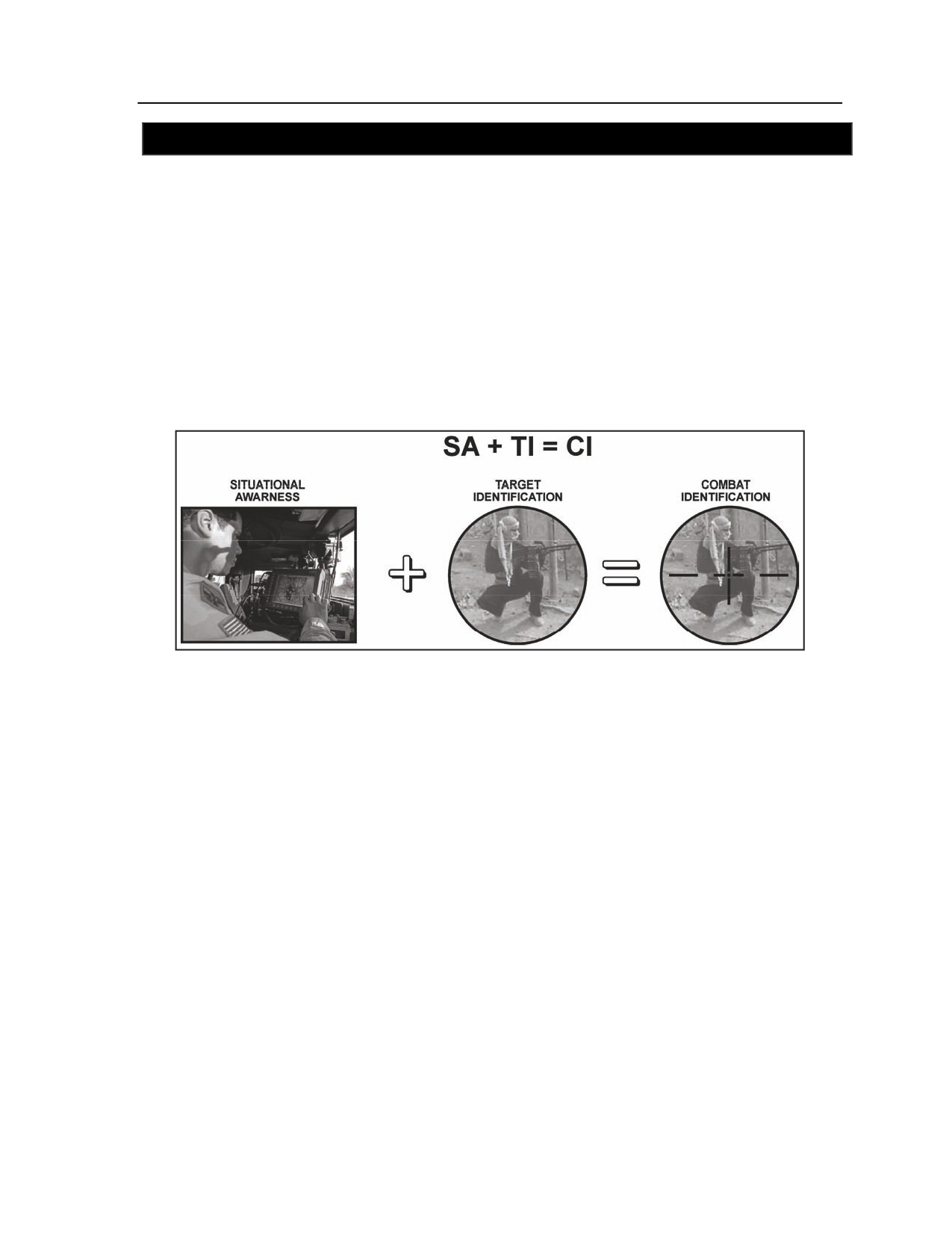
Appendix D
SECTION V - FRATRICIDE PREVENTION PRINCIPLES AND PROCEDURES
D-19. In many situations, the primary cause of fratricide is the lack of positive target identification. To
prevent fratricide incidents, commanders and leaders at all levels must ensure positive target identification
before they issue commands to fire. In addition, all units must accurately report their locations during
combat operations, and all TOCs and CPs must carefully track the location of all subordinate elements in
relation to all friendly forces. The measures outlined in this section, provide the platoon with a guide to
actions it can take to reduce and/or prevent fratricide risk. These guidelines are not directive in nature, nor
are they intended to restrict initiative. Commanders and leaders must learn to apply them as appropriate
based on the specific situation and METT-TC factors.
PRINCIPLES OF FRATRICIDE PREVENTION
D-20. At the heart of fratricide reduction and prevention are the key principles covered in the following
discussion. When considering these principles, all leaders should consider the formula SA+TI=CID, as
shown in Figure D-1.
Figure D-1. Formula for fratricide prevention
MAINTAIN SITUATIONAL AWARENESS
D-21. Focus on such areas as current intelligence; unit locations and/or dispositions; denial areas
(minefields/scatterable mines); contaminated areas, such as improved conventional munitions and CBRN;
SITREPs; and METT-TC factors. FBCB2 will provide the reconnaissance platoon with a distinct
advantage in situational awareness.
MAINTAIN EFFECTIVE FIRE CONTROL
D-22. Ensure fire commands are accurate, concise, and clearly stated. Make it mandatory for crewmen to
ask for clarification of any portion of the fire command they do not completely understand. Ensure
crewmen get in the habit of obtaining target confirmation and permission to fire from their leaders, before
engaging targets they assume are threat elements. Know not only who will be in and around the area of
operations, but what is in your area of operations, such as minefields, industrial contaminated areas,
religious sites, and CBRN areas.
ESTABLISH AN EFFECTIVE COMMAND CLIMATE EMPHASIZING FRATRICIDE PREVENTION
D-23. Enforce fratricide prevention measures, placing special emphasis on the use of doctrinally sound TTP.
Risks that create situations where fratricide may occur should be expressed in OPORDs and applicable
FRAGOs. Leaders must ensure rehearsals address these risks as they occur in the course of the operation.
D-4
FM 3-20.98
3 August 2009
Fratricide Prevention and Combat Identification
FRATRICIDE PREVENTION MEASURES
D-24. Commanders, leaders, and vehicle crewmen should adhere to the following guidelines,
considerations, and procedures in ensuring fratricide reduction and prevention:
z
Recognize the signs of stress. Maintain unit cohesion by taking quick, effective action to
alleviate stress.
z
Conduct individual, leader, and collective (unit) training covering fratricide awareness, target
identification and recognition, and fire discipline.
z
Develop a simple, decisive plan.
z
Give complete and concise mission orders.
z
To simplify mission orders, use SOPs that are consistent with doctrine. Periodically review and
update SOPs as needed.
z
Strive to provide maximum planning time for leaders and subordinates.
z
Use common language/vocabulary and doctrinally correct standard terminology and control
measures, such as CFL, zone of engagement, and RFL.
z
Ensure that thorough coordination is conducted at all levels.
z
Plan for and establish effective communications.
z
Plan for collocation of CPs whenever it is appropriate to the mission, such as during a passage
of lines.
z
Designate and employ liaison officers (LNO) as appropriate.
z
Make sure ROE and ROI are clear and understood.
z
Conduct rehearsals whenever the situation allows the troop adequate time to do so. Rehearse and
war-game potential fratricide scenarios with emphasis on unit recognition devices and signals.
z
Be in the right place at the right time. Use position location/navigation devices, such as global
positioning systems (GPS) and position navigation (POSNAV). Know your location and the
locations of adjacent units
(left, right, leading, and follow-on), and synchronize tactical
movement. If the troop or any element becomes lost or disoriented, leaders must know how to
contact higher headquarters immediately for instructions and assistance.
z
Include a discussion of fratricide incidents in all AARs.
z
Maintain situational awareness and understanding so circumstances of fratricide can be
anticipated, and be planned for minimization.
FRATRICIDE RISK ASSESSMENT
D-25. The guidelines shown in Figure D-2 illustrate a technique which platoons can use for evaluating
fratricide risks in the context of mission requirements. This technique includes a list of six mission
accomplishment factors that affect the risk of fratricide, along with related considerations for each factor.
Leaders should assess the potential risk in each area (low, medium, or high) and assign a point value to
each (one point for low risk, two for medium risk, three for high risk). They then add the point values to
calculate the overall fratricide assessment score.
D-26. The resulting score is used only as a guide, however. The leader’s final assessment must be based
both on observable risk factors, such as those listed on the worksheet, and on his “feel” for the intangible
factors affecting the operation. Note that descriptive terms are listed only in the low- and high-risk
columns. The assessment of each factor will determine whether the risk matches one of these extremes or
lies somewhere between them as a medium risk.
3 August 2009
FM 3-20.98
D-5
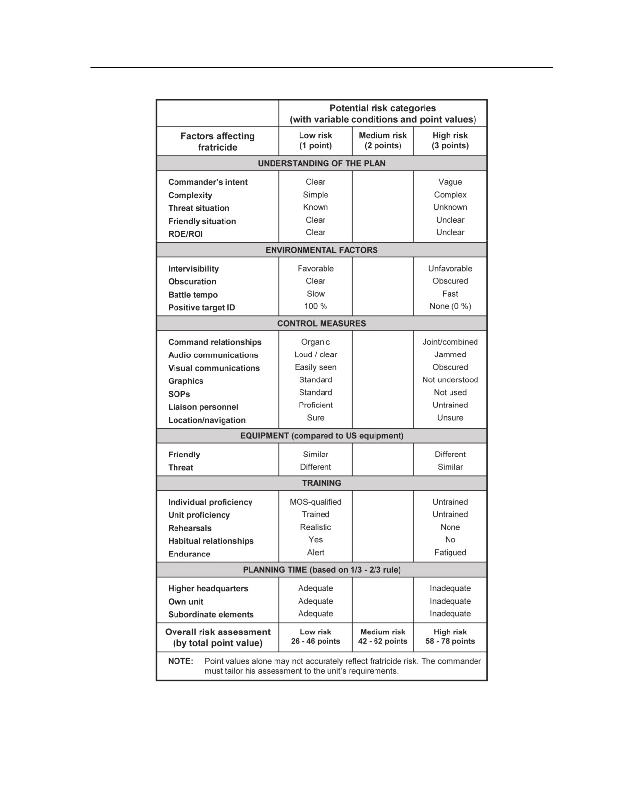
Appendix D
Figure D-2. Example fratricide risk guidelines
D-6
FM 3-20.98
3 August 2009
Fratricide Prevention and Combat Identification
PRINCIPLES OF FIRE CONTROL
D-27. Fire control ensures that critical targets are engaged first and with the correct weapon system. When
employed properly, weapon systems avoid target overkill, conserve ammunition, create standoff, and
prevent fratricide. The principles of fire control assist in defining the area of operations and empowering
the personnel to make decisions with minimum supervision.
MASS THE EFFECTS OF FIRE
D-28. Massing fires entails focusing fires at critical points and distributing the effects. For example,
sections concentrating a weapon system on a single target may ensure its destruction or suppression.
However, that fire control technique will probably not achieve a decisive effect on the enemy formation or
position permitting the enemy to escape and report your presence.
DESTROY THE GREATEST THREAT FIRST
D-29. The danger posed by the enemy depends on enemy weapons, range, and positioning. Presented with
multiple targets, a unit will, in almost all situations, initially concentrate fires to destroy the greatest threat,
and then distribute fires over the remainder of the enemy force (tanks, APCs, trucks, rocket-propelled
grenade [RPG] teams, and finally troops in the open).
AVOID TARGET OVERKILL
D-30. Target overkill wastes ammunition and ties up weapons that are better employed acquiring and
engaging other targets and can compromise the cover and concealed positions of potentially critical
reconnaissance platforms. On the other hand, the idea of having every weapon engage a different target
must be tempered by the requirement to destroy the greatest threats first.
EMPLOY THE BEST WEAPON FOR THE TARGET
D-31. Using the appropriate weapon for the target increases the probability of rapid threat destruction or
suppression; at the same time, it saves ammunition. Target type, range, and exposure are key factors in
determining the weapon and ammunition that should be employed, as are weapons and ammunition
availability and desired effects. Additionally, leaders should consider individual and crew capabilities
when deciding on the employment of weapons. The troop commander task organizes and arrays his assets
based on the terrain, threat/enemy, and desired effects of fires (such as TOW missiles for tanks, 25-mm
chain gun for APCs and trucks, and machine guns for troops and RPG teams).
Note. New TOW ammunition has been made available for platoons to use against aerial targets
and reinforced structures.
MINIMIZE FRIENDLY EXPOSURE
D-32. Units increase their survivability by using cover and concealment and exposing themselves to the
enemy only to the extent necessary to engage the enemy (hull or turret down positions) effectively. Crews
and squads minimize their exposure by constantly seeking effective available cover, attempting to engage
the enemy from the flank, remaining dispersed, firing from multiple positions, and limiting engagement
times.
PREVENT FRATRICIDE
D-33. Leaders must be proactive in reducing the risk of fratricide and noncombatant casualties. Knowledge
and employment of applicable ROE are the primary means preventing noncombatant casualties. There are
additional tools to assist in this effort; identification training for combat vehicles and aircraft; the units
weapons safety posture; the weapons control status; recognition markings; and knowledge of the common
3 August 2009
FM 3-20.98
D-7
Appendix D
operational picture (COP). Scout positions which have a visual contact but cannot clearly identify that
contact may make a net call to see if any other element has a visual on that contact. Details may be visible
to anther scout in a different location.
PLAN FOR EXTREME LIMITED VISIBILITY CONDITIONS
D-34. At night, limited visibility fire control equipment enables the engagement of threat forces from
nearly the same ranges that are applicable during the day. Obscurants such as dense fog, obscurant
munitions, and blowing sand, however, can reduce the capabilities of thermal and infrared equipment.
Although decreased acquisition capabilities have minimal effect on area fire, point target engagements will
likely occur at decreased ranges. Another alternative is the use of visual or IR illumination when there is
insufficient ambient light for passive light intensification devises.
DEVELOP CONTINGENCIES FOR DIMINISHED CAPABILITIES
D-35. Leaders initially develop plans based on their unit’s maximum capabilities; they make backup plans
for implementation in the event of casualties or weapon damage or failure. Leaders should develop plans
for what they view as the most probable occurrences. Platoon leaders should build redundancy into these
plans, such as having two systems observe the same NAI, is an invaluable asset when the situation (and the
number of available systems) permits.
SECTORS OF FIRE
D-36. Sectors of fire are areas that are covered by observation and fire, starting at the weapon system and
extending to its maximum effective range. Platoon leaders must ensure that each scout section’s field of
fire overlaps with adjacent section’s sectors of fire. The platoon’s fire plan must cover dead space within
and between sections to maintain coverage. Considerations include the following:
z
The primary sector of fire is the main area on which the leader wishes the weapon system to
concentrate its firepower, usually overlooking a main engagement area. The primary sector of
fire is covered by the primary and alternate positions.
z
The secondary sector of fire is assigned to engage a secondary avenue of approach or cover
another vehicle’s sector, if it is required. The secondary sector of fire is covered by the
supplementary position.
SCANNING TECHNIQUES
D-37. When scanning in open terrain, scouts will scan left to right and near to far. Urban terrain offers
more cover and concealment to possible threats. A third scanning dimension is added to target detection,
scanning up and down as shown. Figures D-3 through D-6 illustrate scanning techniques in various
environments.
D-8
FM 3-20.98
3 August 2009
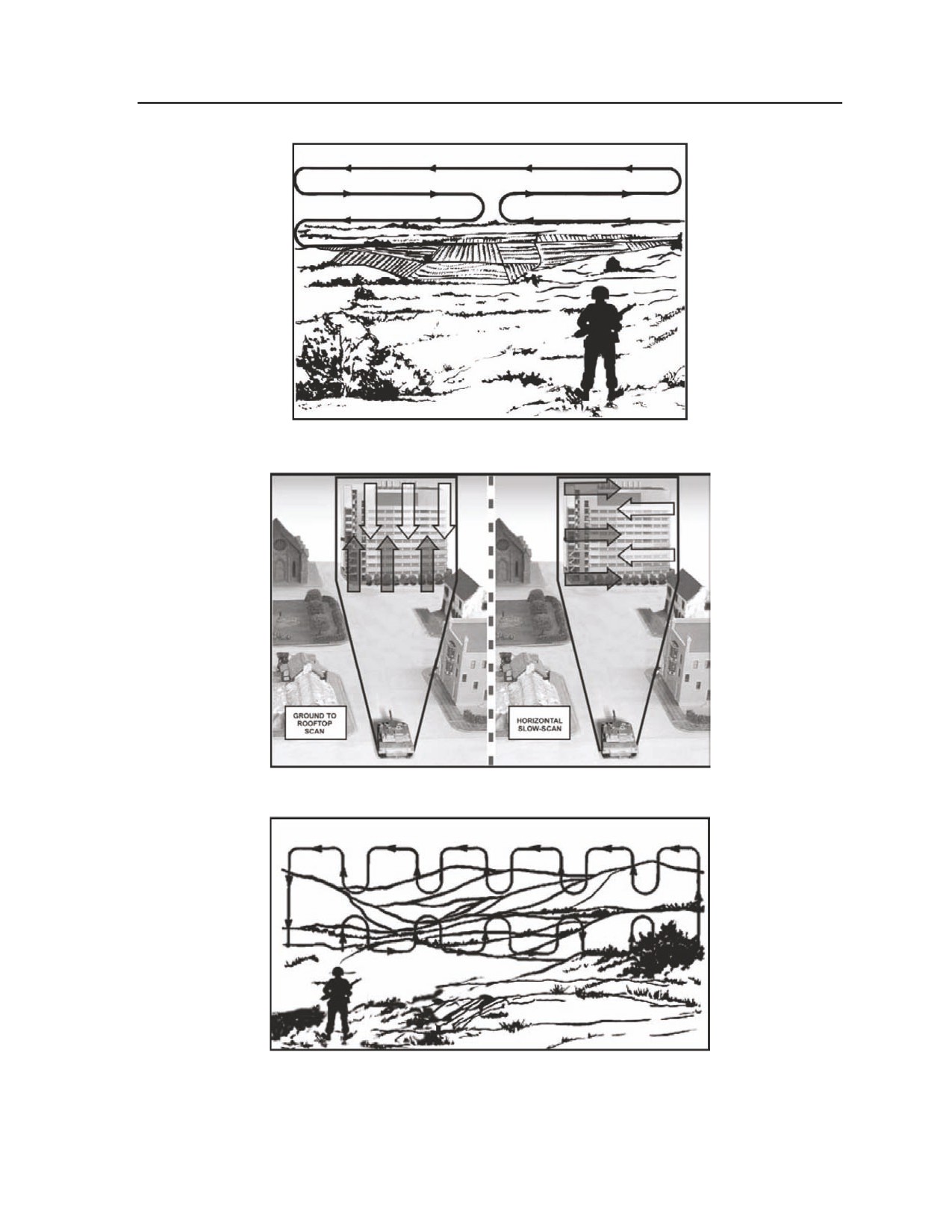
Fratricide Prevention and Combat Identification
Figure D-3. Scanning techniques (part one)
Figure D-4. Scanning techniques (part two)
Figure D-5. Scanning techniques (part three)
3 August 2009
FM 3-20.98
D-9
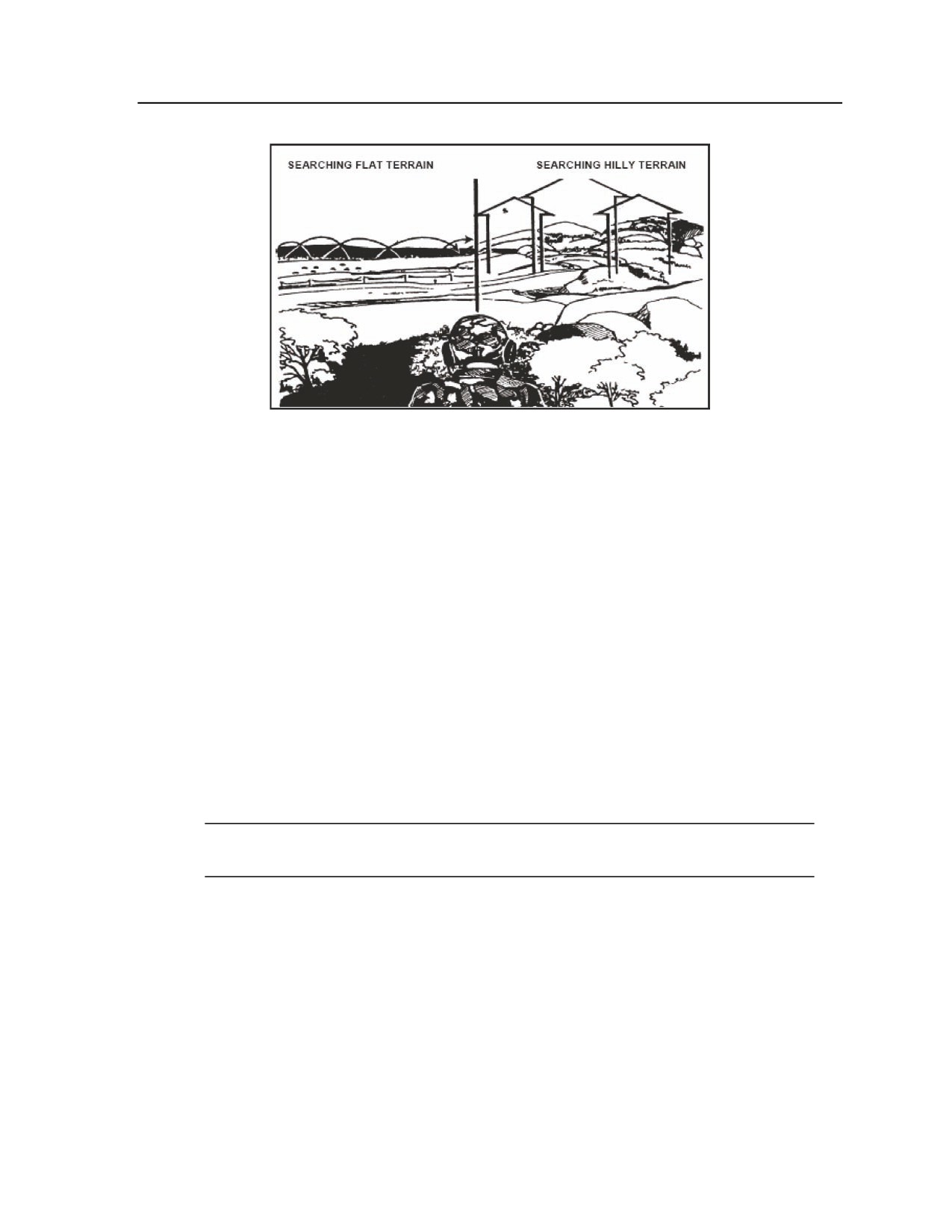
Appendix D
Figure D-6. Scanning techniques (part four)
ENGAGEMENT AREAS
D-38. The platoon leader must plan to use the massed effects of direct fires, CCA, CAS, and indirect fires
at the appropriate times or simultaneously. Obstacles should be used in the engagement area to turn, fix,
and contain the enemy in the engagement area for accurate fires.
TARGET REFERENCE POINTS (TRP)
D-39. A TRP is an easily recognizable point on the ground (natural or man-made) used for identifying
enemy targets or controlling direct fires. TRPs are used to designate targets of opportunity, shift fires, or
assign sectors of fire.
D-40. In the defense, TRPs are assigned for vehicles along mounted avenues of approach. In the offense,
TRPs are assigned on likely enemy locations or on prominent terrain features. To avoid confusion, the
number of TRPs should be limited to the number required to effectively control and distribute fires. When
using a TRP to hand off targets, compass directions (north, east, south, and west) are used rather than right
or left, because each vehicle may be viewing the TRP from a different direction. The FIST will assign each
TRP a target identification number. The target identification number consists of two letters and four
numbers (for example, AB5010). These identification numbers are recorded on range cards in the data
section for easy reference and control. To simplify fire commands, TRPs may be referred to by the last
three digits (for example, TRP AB5010 may be referred to as TRP 010).
Note. A TRP and indirect fire target may be designated in the same location with a common
name for clarity.
PHASE LINES
D-41. A phase line is a simple and effective linear control measure normally used to control movement; it can
also be used to control and distribute the fire of several widely separated vehicles. Leaders use phase lines to
indicate to crews when to fire and when to displace to an alternate position. The phase line may also be
designated as a disengagement line. Any prominent (natural or man-made) linear terrain feature (ridgeline,
river or stream, road, or railroad track) can be used as a phase line. In either offensive or defensive operations,
phase lines can be used to start or stop firing simultaneously, shift fire to another sector, or indicate when
vehicles are to move to alternate or supplementary positions. Platoon leaders and PSGs must control
movement of sections with established phase lines or with the addition of platoon internal phase lines to
prevent sections from moving in front of each other, thus creating a fratricide situation.
D-10
FM 3-20.98
3 August 2009
Fratricide Prevention and Combat Identification
SECTION VI - STOPPING A FRIENDLY FIRE INCIDENT
D-42. The reconnaissance platoon may become involved in a friendly fire incident in one of several ways:
as the victim of the fire; as the firing element; or as an observer intervening in an attack of one friendly
element on another. This section covers actions that leaders and crewmen must be prepared to take when
they encounter such situations. For more information see FM 3-20.971.
ACTIONS AS VICTIM OF FRIENDLY FIRE
D-43. The following are recommended actions at crew and leader level in the event the crew falls victim to
friendly fires:
z
React to contact until you recognize friendly fire.
z
Cease-fire.
z
Take immediate actions to protect Soldiers and vehicles.
z
Use a visual recognition signal directing the firing unit to cease fire.
z
Report the following on the next higher unit net:
Announce that you are receiving friendly fire.
Request medical assistance as needed.
Give the location and direction of the firing vehicles.
Warn the higher unit not to return fire if you identify the firing unit as friendly.
ACTIONS AS FIRING ELEMENT
D-44. The following are recommended actions at crew and leader level when the crew has engaged
friendly forces:
z
Cease-fire.
z
Report the following on the next higher net:
z
Identification of the engaged friendly force (if the unit is unidentified, report number and type of
vehicles).
z
The location of the incident.
z
Direction and distance to the engaged force.
z
The type of fire.
z
The target effects.
ACTIONS AS OBSERVER OF FRIENDLY FIRE
D-45. The following are recommended actions at crew and leader level in the event the crew observes a
friendly fire incident:
z
Seek cover and protect yourself.
z
Use a visual recognition signal directing the firing unit to cease-fire.
z
Report the following on the next higher net:
Identification of the engaged friendly force (if the unit is unidentified, report number and
type of vehicles).
The location of the incident.
Direction and distance to the victim and the firing unit.
The type of fire.
The target effects.
z
Provide assistance as needed (when it is safe to do so).
3 August 2009
FM 3-20.98
D-11
Appendix D
LEADER RESPONSIBILITIES
D-46. In all situations involving the risk of fratricide and friendly fire, leaders must be prepared to take
immediate actions to prevent casualties as well as equipment damage or destruction. Recommended actions
in fratricide situations include the following:
z
Identify the incident and order the parties involved to cease fire.
z
Conduct an in-stride risk assessment.
z
Identify and implement controls to prevent the incident from recurring.
SECTION VII - COMBAT IDENTIFICATION (CID)
D-47. It is highly unlikely that Army forces will operate independently of other U.S. ground, air, or naval
forces in future combat operations. Combat operations within joint task force structures will invariably
place Army units in close proximity to other U.S. and multinational units with different equipment and
uniforms. Effective combat identification measures and tactics, techniques, and procedures (TTP) will be
even more important within this context.
CID MEASURES
D-48. CID measures must be established early in all operational orders and planning cycles to ensure
subordinates fully understand and have opportunity to implement all established measures prior to combat
operations.
D-49. Combat identification measures must be consistent with ROE and not interfere unduly with unit and
individual rights and responsibilities to engage enemy forces.
D-50. No perfect combat identification system exists, but by analyzing combat identification requirements
from planning to execution, friendly forces can be more effective in combat and reduce the potential for
fratricide and undesired collateral damage. Soldiers make the Shoot/No Shoot decision at the point of
engagement and must be fully proficient in all aspects of CID. This includes situational awareness and
understanding of doctrine, TTP, ROE and technology to directly address fratricide avoidance and expedite
force sorting for improved combat effectiveness. While technology aids the Soldier, it has limitations
because not all entities are equipped with a blue force tracker (BFT) or similar device. BFT does not
automatically report enemy or neutral entities.
Note. None of the cooperative technologies currently in use or being developed truly identifies
friend or foe; they can only identify friend or unknown.
SAFETY CONSIDERATIONS
D-51. Leaders at all levels must be aware of the safety considerations involved in full-spectrum operations.
All personnel in both the light and heavy units must be aware of these considerations to prevent
unnecessary casualties.
D-52. Armored vehicle crewmen occupied with maneuvering or controlling their vehicle are often unable
to see dismounted Soldiers operating close to their vehicle. In these conditions, the crew is focused on the
enemy or on potential enemy locations rather than any nearby dismounts. The use of JCIMS CID marking
system capabilities like the dismounted Soldier combat identification marking system (DCIMS) and
Phoenix infrared lights can help identify and illuminate other friendly vehicles and dismounted Soldiers at
night. Employment of JCIMS will assist vehicle commanders and gunners and allow the driver to assist in
positive identification of friendly platforms and Soldiers reducing fratricide across the Army.
D-53. JCIMS marking devices are used in conjunction with forward looking infrared (FLIR) optics and
image intensification devices (such as NVGs) to assist in identifying friendly vehicles and Soldiers at the
point of engagement. The markings must be installed, turned on, and visible on friendly vehicles and
D-12
FM 3-20.98
3 August 2009
Fratricide Prevention and Combat Identification
dismounted Soldiers to be effective; in addition, operational status in accordance with the unit SOP and
specifics contained in the OPORD must be included in PCI procedures to ensure compliance. JCIMS
components for vehicle and personnel include the following:
z
Combat identification panels (CIP).
z
Thermal identification panel.
z
Phoenix beacons (infrared lights).
z
Dismounted combat identification marking system (DCIMS).
z
Automated target recognition devices.
D-54. The potential for fratricide will continue to be a problem because new technologies allow target
engagements by vehicle-mounted weapons beyond the visual identification range. Two systems in use to
eliminate fratricide are the following:
z
The battlefield combat identification system (BCIS) allows the platform gunner or commander
to rapidly aim at their weapon system at and identify other friendly BCIS equipped platforms at
the point of engagement. The BCIS incorporates a secure digital data link (DDL) which
provides local SA updates (friend identification, GPS location, and unit identification) to
vehicles within one kilometer of each other at 5 to 6 second intervals. This DDL also enables
SA information exchange between vehicles when interrogated. Dismounted elements may use
similar technologies to prevent identification as an enemy.
z
The combat identification system dismounted Soldier (CIDDS) system, is a lightweight, laser-
based, question and answer type system, used by the individual Soldiers to positively identify
friendly Soldiers. The system includes a compact, eye safe laser interrogator; a laser detector
assembly; an electronic processor unit. The CIDDS will also be directly interoperable with the
combat ID functions embedded in the Land Warrior equipment suite.
APPLYING DIDEA
D-55. As the scout detects entities and must determine if they need engagement, the scout will use all
available means to sort the entities in his OE into friendly, enemy, or neutral elements. This enables the
scout to employ the weapons at his disposal efficiently against the enemy, without firing on friendly or
neutral elements. The acquisition and location of an object in the OE may be achieved by visual, radar,
electronic signals measurement, or other means. The DIDEA process is a standardized and systematic
approach to apply CID and ROE to target engagements. DIDEA is applied at the individual Soldier level
through crew level for a firing platform. The engagement process begins with the application of each step
in DIDEA.
SITUATIONAL AWARENESS (SA)
D-56. SA is immediate knowledge of the conditions of the AO surrounding the Soldier. Scouts begin
developing their SA once they receive WARNOs and FRAGOs for missions.
D-57. The key attributes of SA are gaining, maintaining, and updating information through—
z
Accuracy and timeliness of reporting.
z
An adequate density of friendly position, location, and information generating systems.
z
Interoperability of friendly force C2/SA systems in the OE.
D-58. SA is achieved by having—
z
A constantly updated picture of the AO.
z
An accurate assessment of friendly, enemy, neutral, and other operations within the unit’s OE.
z
The ability to quickly determine the context and relevance of unfolding events.
D-59. Other sources of information and knowledge that provide SA are OPORDs/FRAGOs and combat
reports. The platoon leader down to the squad leader is responsible for keeping subordinates aware of
changes in the situation (friendly, enemy, and neutral). SA can be displayed on FBCB2 or manually posted
on a map showing the position and tracking of friendly units and the reported locations of enemy, neutral,
3 August 2009
FM 3-20.98
D-13
Appendix D
and unknown entities. The automated position reporting capability of these systems relieves radio voice
network traffic and enables leaders to focus more of their time on finding and killing the enemy and less
time on determining friendly dispositions. Scouts may post the original time of a SPOTREP allowing the
scout to track updates of an entity without confusing new reports as additional enemy elements in the
operational space.
Note. Attaining and maintaining SA of the OE is every Soldier’s responsibility.
TARGET IDENTIFICATION (TI)
D-60. TI is the accurate and timely characterization of a detected object in the AO as friend, enemy, or
neutral. This is time sensitive and is the basis of a Soldier’s “engage/don’t engage” decision. In direct fire
situations, regardless of the system used to identify a target, the Soldier must achieve visual positive
identification prior to executing the engagement. Reconnaissance and scout platoons may detect entities on
the ground through remote sensors, however a friendly element must gain a visual on the entity to
determine it is an enemy. Scouts must remember that not all elements in the AO have technology assisting
with target identification. There are two types of TI systems.
Cooperative TI
D-61. Cooperative TI entails systems in which a query is sent out and a response is given that “I am a
friend” with cooperative equipped systems. Cooperative systems may consist of high-tech query systems
that electronically identify friendly elements, or may be as low-tech as a sentry issuing a challenge and
waiting for a password. Cooperative TI directly addresses fratricide avoidance by positively identifying
friendly elements. However, the lack of a friendly response does NOT identify the target as enemy. The
Soldier must still use the DIDEA process to identify entities; Cooperative TI technologies should never be
used as the sole criteria to engage. Mechanical issues or enemy action may render the Cooperative TI
technology inoperative, or friendly units/allies in the OE may not be equipped with compatible Cooperative
TI technologies. Soldiers with or without Cooperative TI technology cannot engage unknown entities in
the AO prior to positive visual identification. Current cooperative TI technologies include identification
friend or foe (IFF), OE TI devices, and radio based combat identification systems.
Noncooperative TI
D-62. Noncooperative TI exploits physical characteristics of the object and requires no cooperative action
or response on the part of the object. These devices may be active or passive and employ an array of
technologies including those permitting detection and analysis of signal emissions, noise emissions, and
radiation emissions; determination and analyses of physical dimensions and characteristics; and other
factors. Noncooperative TI systems include—
z
Optics such as forward looking infrared (FLIR)
z
Night vision goggles (NVG).
z
Binoculars.
RULES OF ENGAGEMENT (ROE)
D-63. ROE are Department of Defense (DOD) directives issued by competent military authority that
delineate the circumstances and limitations under which Soldiers will initiate and/or continue combat
engagement with other forces encountered. The ROE reflect the law of land warfare and operational
considerations and are primarily concerned with the restraints on the use of force. The ROE are the primary
means by which leaders convey legal, political, diplomatic, and military guidance to Soldiers. The platoon
leaders and PSGs must train scouts thoroughly concerning the ROE, and laws that govern armed conflict
before deployment. During the conduct of operations, leaders ensure Soldiers properly apply the ROE to
preclude inappropriate engagements. Unintentional discharge and even injuries from the discharge may
degrade relations with the local population and host country if deployed.
D-14
FM 3-20.98
3 August 2009
Fratricide Prevention and Combat Identification
D-64. ROE requirements and TTP will depend on the OE. Before a force deploys, the judge advocate
general corps will review and approve through the chain of command the rules by which a target can be
engaged. These rules will address the appropriate EOF.
D-65. The ROI provide guidance for interacting with people encountered in the OE. ROI, when applied
with good interpersonal communication skills, improve the Soldier's ability to accomplish the mission,
while reducing possible hostile confrontations. ROI founded on firm ROE provide the Soldier with the
tools to address non-traditional threats, such as political friction, ideologies, cultural idiosyncrasies,
religious beliefs, and rituals. ROI must be regionally and culturally specific.
D-66. Platoon leaders and PSGs should integrate ROE and ROI into all platoon and section training where
appropriate. The platoon should employ situations where the EOF is played out to prepare the platoon for
real world situations where incidents aggravate the training situation.
TARGET IDENTIFICATION AND FRIENDLY POSITION MARKING
IN AVIATION SUPPORT OPERATIONS
D-67. To maximize the effects of their weapon systems and reduce the incidence of fratricide, aircraft
crews require positive identification of targets and friendly positions before firing their weapons. Aircrews
must easily observe and effectively identify the ground signals marking targets and friendly positions. This
capability is a critical factor in reducing fratricide and maximizing the responsiveness and accuracy of
aerial fires.
D-68. The proximity of friendly forces to targets in the modern OE makes positive marking and
identification especially critical. This discussion addresses several factors that operators should consider
when marking targets and friendly positions; the equipment covered includes target-marking devices,
NVGs, FLIR, thermal imaging system, TV and EO systems, electronic beacons, and laser designators.
PLANNING CONSIDERATIONS
D-69. As noted, aircrews must work closely with the ground forces to accomplish positive marking and
identification of targets and friendly positions. This coordination requires the ground and air commanders
to determine all required marking/identification procedures based on several tactical factors:
z
The signal or combination of signals used must be items commonly carried by ground maneuver
units.
z
Aircrews must be able to acquire signals using available resources on the aircraft, including
normal vision, NODs, and TISs.
z
Signals must be recognizable by the aircrews.
D-70. All participants, ground and airborne, must clearly understand the marking and identification
procedures. Accurate and detailed maps, charts, or other types of imagery will assist the aircrews in
learning the friendly ground scheme of maneuver.
MARKING/IDENTIFICATION TECHNIQUES
D-71. Only the creativity of the ground forces and aircrews limit the methods used to identify and mark
targets and friendly positions. Table D-1 outlines a variety of marking techniques. Ground and air
commanders should use the table as a reference. In any situation, marking methods must be adapted to the
conditions prevalent at the time. Positive air-to-ground communications are also essential in coordinating
and authenticating marking procedures.
D-72. Often, the simplest methods are the best. Traditional signaling devices such as flares, strobes, and
signaling mirrors may be quite effective in marking friendly positions. Scouts use common signaling
techniques such as obscurant munitions, laser pointers, and tracers in marking targets or orienting aircrews
on enemy positions.
3 August 2009
FM 3-20.98
D-15
Appendix D
D-73. Other devices are available to aid in the recognition of friendly forces and equipment where the fluid
tactical situation or the intermingling of friendly and enemy forces in the close fight makes identification
difficult. For example, the use of glint tape, combat identification panels (CIP), and infrared beacons can
assist in the clear identification of friendly ground forces. Such factors as ground lighting, thermal contrast,
and intermediate obstructions can influence the effectiveness of these devices.
D-74. All aerial crewmembers and ground maneuver leaders should understand the strengths and
weaknesses of available aviation sensors when employed in conjunction with a variety of target-marking
equipment and methods. Time permitting, attack aircraft may input a target grid into the aircraft
GPS/inertial navigation system to provide fire control cues to the target (such as range, heading, and time);
these cues can result in quicker target acquisition and help to distinguish friendly positions from targets and
enemy positions. Because CCA missions may be “danger close” with short firing ranges, both aircrews and
ground forces should expect to have minimum tracking time and thus minimum time to optimize the
aircraft sensors.
D-16
FM 3-20.98
3 August 2009
Fratricide Prevention and Combat Identification
Table D-1. Target and friendly position marking methods
Friendly
Target
Method
Day/Night
Assets
Remarks
Marks
Marks
Easily identifiable. May
compromise friendly position,
obscure target, or warn of fire
SMOKE, obscurant
Day/night
All
Good
Good
support employment.
Structures may make
placement difficult.
Easily identifiable. May
compromise friendly position,
obscure target, or warn of fire
SMOKE, obscurant
All/NOD at
support employment.
Day/night
Good
Good
(IR)
night
Structures may make
placement difficult. Night
marking is greatly enhanced
using IR reflective obscurant.
GROUND BURST
Easily identified. May wash
Day/night
All
N/A
Good
ILLUMINATION
out NODs.
Avoids compromise of friendly
location. Dependent on
weather and available light
SIGNAL MIRROR
Day
All
Good
N/A
and may be lost in reflections
from other reflective surfaces
(such as windshields,
windows, or water).
Highly visible to all.
Compromises friendly
position and warns of fire
SPOTLIGHT
Night
All
Good
Marginal
support employment.
Effectiveness dependent on
degree of urban lighting.
Visible to all with NODs. Less
likely to compromise than
IR SPOTLIGHT
Night
All NODs
Good
Marginal
overt light. Effectiveness
dependent on degree of
urban lighting.
IR LASER POINTER
Effectiveness dependent on
Night
All NODs
Good
Marginal
(BELOW .4 WATTS)
degree of urban lighting.
Less affected by ambient
light and weather conditions.
IR LASER POINTER
Highly effective under all but
Night
All NODs
Good
Good
(ABOVE .4 WATTS)
the most highly lit or worst
weather conditions. IZLID-2
is the current example.
Highly visible to all. Risk of
compromise is high.
VISUAL LASER
Night
All
Good
Marginal
Effectiveness dependent on
degree of urban lighting.
Highly effective with PGM.
Because of very restrictive
LASER
PGM or LST
laser acquisition cone,
Day/Night
N/A
Good
DESIGNATOR
equipped
requires line of sight to
target. May require pre-
coordination of laser codes.
May compromise position.
May be difficult to distinguish
marking rounds from other
TRACER
Day/Night
All
N/A
Marginal
gunfire. During daytime use,
may be more effective when
used to kick up dust
surrounding target.
3 August 2009
FM 3-20.98
D-17
Appendix D
Table D-1. Target and friendly position marking methods
Friendly
Target
Method
Day/Night
Assets
Remarks
Marks
Marks
Easily masked by urban
structures and lost in thermal
clutter. Difficult to acquire,
CHEMICAL HEAT
Day/Night
All FLIR
Poor
N/A
but can be effective when
SOURCES
used to contrast cold
background or when ACFT
indicates general location.
Visible by all. Effectiveness
STROBE (OVERT)
Day/Night
All
Marginal
N/A
dependent on degree of
urban lighting.
Visible to all NODs.
Effectiveness dependent up
STROBE (IR)
Night
All NODs
Good
N/A
degree of urban lighting.
Coded strobes aid in
acquisition.
Ideal friendly marking device
for
AC-130 and some USAF
fixed-wing aircraft (not
compatible with Navy or
Marine aircraft). Least
ELECTRONIC
Day/Night
See Remarks
Excellent
Good
impeded by urban terrain.
BEACON
Can be used as a TRP for
target identification.
Coordination with aircrews
essential to ensure
equipment and training
compatibility.
Visible by all. Easily identified
FLARE (OVERT)
Day/Night
All
Good
N/A
by aircrews.
Visible to all NODs. Easily
FLARE (IR)
Night
All NODs
Good
N/A
identified by aircrews.
Not readily detectable by
GLINT/IR PANEL
Night
All NODs
Good
N/A
threat. Very effective except
in highly lit areas.
Provides temperature
COMBAT
contrast on vehicles or
IDENTIFICATION
Day/night
All FLIR
Good
N/A
building. May be obscured by
PANEL
urban terrain.
Only visible during daylight.
VS-17 PANEL
Day
All
Marginal
N/A
Easily obscured by
structures.
Provides unique signature.
May be obscured by
SPINNING
structures. Provides a distinct
CHEM LIGHT
Night
All
Marginal
N/A
signature easily recognized.
(OVERT)
Effectiveness dependent on
degree of urban lighting.
Provides unique signature.
SPINNING
May be obscured by
CHEM LIGHT
Night
All NODs
Marginal
N/A
structures. Effectiveness
(IR)
dependent on degree of
urban lighting.
D-18
FM 3-20.98
3 August 2009
Appendix E
Composite Risk Management and Environmental
Protection
Risk is the chance of injury or death for individuals and damage to or loss of vehicles
and equipment. These risks and the potential for risks are always present in every
combat and training situation to include damaging the environment. Composite risk
management (CRM) must take place at all levels of the chain of command during
each phase of every operation to protect Soldiers, the Army, and environmental
resources. The reconnaissance or scout platoon leader, his NCOs, and all other
platoon Soldiers must know how to use CRM, coupled with fratricide reduction
measures, to ensure that they execute the mission in the safest possible manner,
within mission constraints. This appendix outlines the process that leaders can use to
identify hazards and implement a plan to address each identified hazard. It includes a
detailed discussion of the responsibilities of the troop’s leaders and Soldiers in
implementing a sound CRM program. It also covers the parallel process of assessing,
managing, and alleviating environmental risks and hazards. For additional
information, refer to FM 5-19 and FM 3-20.971.
SECTION I - COMPOSITE RISK MANAGEMENT PROCEDURES
E-1. CRM is the Army’s primary decision-making process for identifying hazards and controlling risks
across the full spectrum of Army missions, functions, operations, and activities that have the potential to
injure or kill personnel, damage or destroy equipment, or otherwise impact mission effectiveness. The
Army used to separated risk into two categories:
z
Accident risk. This covers any type of risk involving friendly forces, such as vehicle collisions,
operational mistakes, and equipment and communications failures. It includes hazards imposed
on the troop because of terrain, weather, or mission requirements
(such as traveling an
unimproved road at night in a snow storm).
z
Threat risk. This covers all types of risk posed by contact with threat/enemy forces, as well as
risk that may arise in gaining or breaking threat contact. Tactical hazards are those imposed on
friendly forces by the enemy, such as ATGM positions or untemplated enemy positions on the
flanks.
E-2. While these two areas of concern remain, the primary premise of CRM is that it does not matter
where or how the loss occurs. The result is the same: decreased combat power or mission effectiveness.
The guiding principles of CRM are the following:
z
Integrate CRM into all phases of missions and operations.
z
Make risk decisions at the appropriate level. CRM is only effective when the information is
passed to the appropriate level of command for decision.
z
Accept no unnecessary risk unless the potential gain or benefit outweighs the potential loss.
z
Apply the process cyclically and continuously. CRM is a continuous process applied across the
full spectrum of Army training and operations, individual and collective day-to-day activities
and events, and base operations functions.
z
Do not be risk averse. Identify and control the hazards; then complete the mission.
3 August 2009
FM 3-20.98
E-1
Appendix E
E-3. The primary objective of CRM is to help units protect their combat power, enabling them to achieve
success quickly and decisively, with minimum losses. Leaders of the reconnaissance or scout platoon must
always remember that the effectiveness of the process depends on SA. They should never approach CRM
with a “one size fits all” solution mentality. Rather, in performing the five steps of CRM, they must keep in
mind the essential tactical and operational factors that make each situation unique.
STEP 1 - IDENTIFY HAZARDS
E-4. A hazard is a source of danger. It is any existing or potential condition that could entail injury,
illness, or death of personnel; damage to or loss of equipment and property; or other sorts of mission
degradation.
E-5. The reconnaissance/scout platoon leader must identify the hazards associated with all aspects and
phases of the platoon’s mission, paying particular attention to the factors of METT-TC. CRM must never
be an afterthought. The platoon leader must begin the process during his troop-leading procedures and
continue it throughout the operation. Figure E-1 lists possible sources of risk that the reconnaissance/scout
platoon might face during a typical tactical operation.
E-2
FM 3-20.98
3 August 2009
Composite Risk Management and Environmental Protection
SOURCES OF OPERATIONAL RISK
MISSION
• Duration of the operation and size/range of the AO.
• Complexity/clarity of the plan. (Is the plan well developed and easily understood?)
• Proximity and number of maneuvering units.
ENEMY
• Inadequate knowledge of the enemy situation to include enemy capabilities.
• Limited availability of time and resources to conduct reconnaissance.
TERRAIN AND WEATHER
• Limited visibility conditions, including light, dust, fog, and smoke.
• Precipitation and its effect on mobility.
• Extreme heat or cold.
• Additional natural hazards (broken ground, steep inclines, and water obstacles).
TROOPS AND SUPPORT AVAILABLE
• Platoon organization, including number of vehicles and type of weapons/equipment.
• Soldier/leader inexperience, limited proficiency, and low equipment readiness.
• Lack of experience the units conducting the operation have working together.
• Danger areas associated with the troop’s weapon systems.
• Lack of Soldier/leader rest.
• Non-acclimatization to environment.
• Impact of new leaders and/or Soldiers.
TIME AVAILABLE
• Limited time available for TRPs and rehearsals by subordinates.
• Limited time available for PCCs/PCIs.
CIVIL CONSIDERATIONS
• Restrictive applicable ROE and/or ROI.
• Contact with civilians
(such as NEOs, refugee or disaster assistance, or
counterterrorism) during stability and/or civil support operations.
• Media contact/inquiries.
Figure E-1. Sources of risk in tactical operations
STEP 2 - ASSESS HAZARDS TO DETERMINE RISKS
E-6. Hazard assessment is the process of determining the direct impact of each hazard on an operation (in
the form of hazardous incidents). Use the following steps:
z
Determine which hazards can be eliminated, minimized, or avoided.
z
Assess each hazard that cannot be eliminated, minimized, or avoided to determine the
probability that the hazard can occur.
z
Assess the severity of hazards that cannot be eliminated, minimized, or avoided. Severity,
defined as the result or outcome of a hazardous incident, is expressed by the degree of injury or
illness (including death), loss of or damage to equipment or property, environmental damage, or
other mission-impairing factors (such as unfavorable publicity or loss of combat power).
z
Taking into account both the probability and severity of a hazard, determine the associated risk
level (extremely high, high, moderate, and low). Figure E-2 summarizes the four risk levels.
Table E-1 provides an outline of the risk assessment matrix used to determine the level of risk.
3 August 2009
FM 3-20.98
E-3

Appendix E
z
Based on the factors of hazard assessment (probability, severity, and risk level, as well as the
operational factors unique to the situation), complete the DA Form 7566 (Composite Risk
Management Worksheet).
Note. DA Form 7566 is available on the Army Knowledge Online (AKO) website. Click on—in
order—the Self Service tab, the DA Pubs & Forms tab, and the Army Forms link. Users can
quickly open/download the DA Form 7566 by going here, http://www.apd.army.mil. When it is
completed, the worksheet can serve as a guide for platoon CRM training, which should cover
how to execute battle drills for actions on contact as well as how to develop and refine SOPs for
actions on contact. Refer to FM 5-19 for detailed guidance and instructions on how to use DA
Form 7566.
LEVELS OF RISK
EXTREMELY HIGH
Someone will die or suffer permanent disability.
HIGH
More often than not, someone will suffer an injury that requires less than 3 months
to heal.
MODERATE
More often than not, someone will require first aid or minor medical treatment.
LOW (WORST CASE)
Someone is likely to need first aid or minor medical treatment.
Figure E-2. Risk levels and impact on mission execution
Table E-1. Risk assessment matrix
Probability
Severity
Frequent
Likely
Occasional
Seldom
Unlikely
Catastrophic
E
E
H
H
M
Critical
E
H
H
M
L
Marginal
H
M
M
L
L
Negligible
M
L
L
L
L
E - Extremely High Risk
H - High Risk
M - Moderate Risk
L - Low Risk
STEP 3 - DEVELOP CONTROLS AND MAKE RISK DECISIONS
E-7. After assessing each hazard, develop one or more controls that will either eliminate the hazard or
reduce the risk (probability and/or severity) of potential hazardous incidents. When developing controls,
leaders consider the reason for the hazard, not just the hazard by itself. Platoon leaders may create
interventions for non military hazards which can defuse the reason for the mission risks.
E-8. A key element in the process of making a risk decision is determining whether accepting the risk is
justified or, conversely, is unnecessary. The decision-maker (the reconnaissance/scout platoon leader, if
applicable) must compare and balance the risk against mission expectations. He alone decides if the
controls are sufficient and acceptable and whether to accept the resulting residual risk. If he determines the
risk is unnecessary, he directs the development of additional controls or alternative controls; as another
option, he can modify, change, or reject the selected COA for the operation. The decision-maker must
E-4
FM 3-20.98
3 August 2009
Composite Risk Management and Environmental Protection
always keep in mind that an important step in reducing or eliminating risk factors is to keep the next higher
level of command involved in and informed of the CRM process.
Note. Risk decisions and controls are especially critical for the BFSB reconnaissance platoon
because of its unique operational requirements and organizational capabilities and limitations.
The platoon leader must be prepared to evaluate the potential risks, make effective risk
decisions, and implement the appropriate controls to mitigate the risks.
STEP 4 - IMPLEMENT CONTROLS
E-9. Controls are the procedures and considerations the unit uses to eliminate hazards or reduce their risk.
Implementing controls is the most important part of the CRM process; this is the chain of command’s
contribution to the safety of the unit. Implementing controls includes coordination and communication with
appropriate superior, adjacent, and subordinate units and with individuals executing the mission. The
reconnaissance/scout platoon leader must ensure that specific controls are integrated into OPLANs,
OPORDs, SOPs, and rehearsals. The critical check for this step is to ensure that controls are converted into
clear, simple execution orders understood by all levels.
E-10. When the leaders conduct a thoughtful risk assessment, the controls will be easy to implement,
enforce, and follow. Examples of CRM controls include the following:
z
Thoroughly brief all aspects of the mission, including related hazards and controls.
z
Conduct thorough PCCs and PCIs.
z
Allow adequate time for rehearsals at all levels.
z
Drink plenty of water, eat well, and get as much sleep as possible (at least 4 hours in any 24-
hour period).
z
Use buddy teams.
z
Enforce speed limits, use of seat belts, and driver safety.
z
Establish recognizable visual signals and markers to distinguish maneuvering units.
z
Enforce the use of ground guides in assembly areas and on dangerous terrain.
z
Establish marked and protected sleeping areas in assembly areas.
z
Limit single-vehicle movement.
z
Establish SOPs for the integration of new personnel.
z
Ensure that all Soldiers are in the proper uniform and/or at the correct MOPP level.
z
Ensure that leaders maintain SA and stay alert to prevent complacency among their Soldiers.
STEP 5 - SUPERVISE AND EVALUATE
E-11. During mission execution, it is imperative for leaders to ensure that CRM controls are properly
understood and executed. Leaders must continuously evaluate the unit’s effectiveness in managing risks to
gain insight into areas that need improvement.
SUPERVISION
E-12. Leadership and unit discipline are the keys to ensuring that effective CRM controls are implemented.
In general, a constant concern for Soldier health and welfare is the key to fostering an environment for
successful, risk-free operations. All leaders are responsible for supervising their mission rehearsals and
execution to ensure standards and controls are enforced. In particular, NCOs must enforce established
safety policies as well as controls developed for a specific operation or task. Techniques include spot
checks, inspections, SITREPs, confirmation briefs, buddy checks, and close supervision.
E-13. During mission execution, leaders must continuously monitor CRM controls, both to determine
whether they are effective and to modify them as necessary. Leaders must also anticipate, identify, and
assess new hazards. They ensure that imminent danger issues are addressed on the spot and that ongoing
planning and execution reflect changes in hazard conditions.
3 August 2009
FM 3-20.98
E-5
Appendix E
EVALUATION
E-14. Whenever possible, the CRM process should also include an after-action review (AAR) to assess
unit performance in identifying risks and preventing hazardous situations. Leaders should then incorporate
lessons learned from the process into unit SOPs and plans for future missions.
SECTION II - IMPLEMENTATION RESPONSIBILITIES
E-15. Leaders and individuals at all levels are responsible and accountable for managing risk. They must
ensure that hazards and associated risks are identified and controlled during planning, preparation, and
execution of operations. The reconnaissance/scout platoon leader and his senior NCOs must look at both
tactical risks and accident risks. The same CRM process is used to manage both types. The platoon leader
alone determines how and where he is willing to take tactical risks. With the assistance of his PSG, NCOs,
and individual Soldiers, the platoon leader manages accident risks.
E-16. Sometimes, despite the need to advise higher headquarters of a risk taken or about to be assumed, the
CRM process may break down. Such a failure can be the result of several factors; most often, it can be
attributed to the following:
z
The risk denial syndrome in which leaders do not want to know about the risk.
z
A Soldier who believes that the risk decision is part of his job and does not want to bother his
platoon leader or section leader.
z
Outright failure to recognize a hazard or the level of risk involved.
z
Overconfidence on the part of an individual or the unit in the capability to avoid or recover from
a hazardous incident.
z
Subordinates not fully understanding the higher commander’s guidance regarding risk decisions.
E-17. The platoon leader gives the platoon direction, sets priorities, and establishes the command climate
(values, attitudes, and beliefs). Successful preservation of combat power requires him to embed CRM into
individual behavior. To fulfill this commitment, the platoon leader must exercise creative leadership,
innovative planning, and careful management. Most important, he must demonstrate support for the CRM
process. The platoon leader, PSG, section, and squad leaders can establish a command climate favorable to
CRM integration by taking the following actions:
z
Demonstrate consistent and sustained CRM behavior through leading by example and by
stressing active participation throughout the CRM process.
z
Provide adequate resources for CRM. Every leader is responsible for obtaining the assets
necessary to mitigate risk and for providing them to subordinate leaders.
z
Understand their own and their Soldier’s limitations, as well as their unit’s capabilities.
z
Allow subordinates to make mistakes and learn from them.
z
Prevent a “zero defects” mindset from creeping into the platoon’s culture.
z
Demonstrate full confidence in subordinates’ mastery of their trade and their ability to execute a
chosen COA.
z
Keep subordinates informed.
z
Listen to subordinates.
E-18. For the platoon leader, his subordinate leaders, and individual Soldiers alike, responsibilities in
managing risk include the following:
z
Make informed risk decisions; establish and then clearly communicate risk decision criteria and
guidance.
z
Establish clear, feasible CRM policies and goals.
z
Train the CRM process. Ensure that subordinates understand the who, what, when, where, and
why of managing risk and how these factors apply to their situation and assigned
responsibilities.
E-6
FM 3-20.98
3 August 2009
Composite Risk Management and Environmental Protection
z
Accurately evaluate the platoon’s effectiveness, as well as subordinates’ execution of risk
controls during the mission.
z
Inform higher headquarters when risk levels exceed established limits.
SECTION III - ENVIRONMENTAL RISK MANAGEMENT PROCESS
E-19. Environmental risk management is similar to CRM and is based on the same philosophy and
principles. Refer to FM 3-20.971 for a detailed description of environmental risk management.
Note. Refer to the discussion of CRM. The environmental risk assessment and management
process consists of the five steps outlined in the following paragraphs.
STEP 1 - IDENTIFY ENVIRONMENTAL HAZARDS
E-20. The platoon leader must identify potential sources of environmental degradation during his analysis
of METT-TC factors. These environmental hazards are conditions with the potential for polluting air, soil,
or water and/or destroying cultural or historical structures, sites, or artifacts. Figure E-3 lists procedures
and considerations for identifying possible sources of environmental risks that the platoon may face during
a typical tactical operation.
STEP 2 - ASSESS ENVIRONMENTAL HAZARDS
E-21. Leaders of the reconnaissance or scout platoon can use the CRM worksheet (DA Form 7566) to
analyze the potential severity of environmental degradation for each training activity. The worksheet
allows them to quantify the risk to the environment as extremely high, high, moderate, or low. Refer to FM
5-19.
STEP 3 - DEVELOP CONTROLS AND MAKE DECISIONS
E-22. Based on the results of the risk assessment, the reconnaissance/scout platoon leader makes decisions
and develops measures to reduce significant environmental risks. Risk decisions are made at a level of
command that corresponds to the degree of risk. Leaders should brief all responsible individuals and
agencies (to include the installation environmental office, if applicable) on the proposed operational and
training plans and on pertinent high-risk environmental factors.
STEP 4 - IMPLEMENT CONTROLS
E-23. The reconnaissance/scout platoon leader and subordinate leaders implement environmental
protection measures at all stages of operational planning, preparation, and execution. They integrate these
measures into plans, orders, SOPs, training performance standards, and rehearsals.
STEP 5 - SUPERVISE AND EVALUATE
E-24. The reconnaissance/scout platoon leader must enforce environmental protection standards during
supervision of all training activities.
3 August 2009
FM 3-20.98
E-7
Appendix E
Figure E-3. Example procedures for identifying environmental risks
E-8
FM 3-20.98
3 August 2009
Appendix F
Chemical, Biological, Radiological, and Nuclear (CBRN)
Operations
Because many potential adversaries have the capability to employ CBRN weapons,
the reconnaissance platoon must prepare to fight in a CBRN environment. To survive
and remain effective in its area of operations (AO), the reconnaissance and scout
platoon must be proficient in contamination avoidance and movement in a CBRN
environment.
SECTION I - CONTAMINATION AVOIDANCE
F-1. Contamination avoidance is defined as taking actions to avoid or reduce the effects of a CBRN
attack and to minimize the effects of CBRN or toxic industrial materials contamination hazards. There are
active and passive measures that can be taken to avoid contamination. These measures include planning
ahead, avoiding detection, providing warning, seeking protection, dispersing assets, remaining mobile, and
covering supplies and equipment. Avoiding contaminated areas minimizes the risk of additional casualties;
it also prevents the degradation of combat power that results when a unit must operate in MOPP level 3 or
4 for extended periods of time. In addition to degrading combat power, the unit is not required to spend the
time and resources needed for decontamination which would keep it from being available for action. For
more information on contamination avoidance, see FM 3-11.3.
GENERAL AVOIDANCE MEASURES
F-2. Contamination avoidance measures include the following:
z
Using passive avoidance techniques.
z
Locating contaminated areas.
z
Identifying CBRN agents.
z
Warning other members of the platoon as well as other units.
z
Reporting CBRN threats to higher headquarters.
F-3. Passive avoidance measures can decrease the possibility of CBRN attack or reduce the effects of an
attack already under way. Effective use of concealment, dispersion, prepared positions, OPSEC, and signal
security reduces the chances of being acquired as a target. The platoon should continually analyze its
vulnerability to chemical or nuclear attack and take appropriate protective measures.
F-4. CBRN attacks and contamination must be detected quickly and reported across the AO. Typically,
an initial warning is issued by radio, audible signals, or hand-and-arm signals once a CBRN danger has
been detected in a close proximity (as close as 200 meters) to some element. During the course of
maneuver, scouts using LRAS3 or other observation systems will not detect a chemical agent (see Figure
F-1). They will however allow scouts to see effects of a CBRN presence. It is preferable for scouts to gain
this visual contact on these areas at a safe distance to avoid contamination. Gunners scanning with the
scout platform’s primary weapon system can pick out details which indicate CBRN danger. Structural
damage is not a typical indicator of a chemical agent; however, people scattered on the ground in a village
without signs of shooting is an indication that something life-threatening has happened, requiring caution
and reporting. Employing scouts to observe a CBRN environment at a distance allows the platoon to retain
freedom of maneuver, report the visual contact, upgrade its MOPP posture, locate overwatch positions, and
request Fox CBRN vehicles for reconnaissance.
3 August 2009
FM 3-20.98
F-1
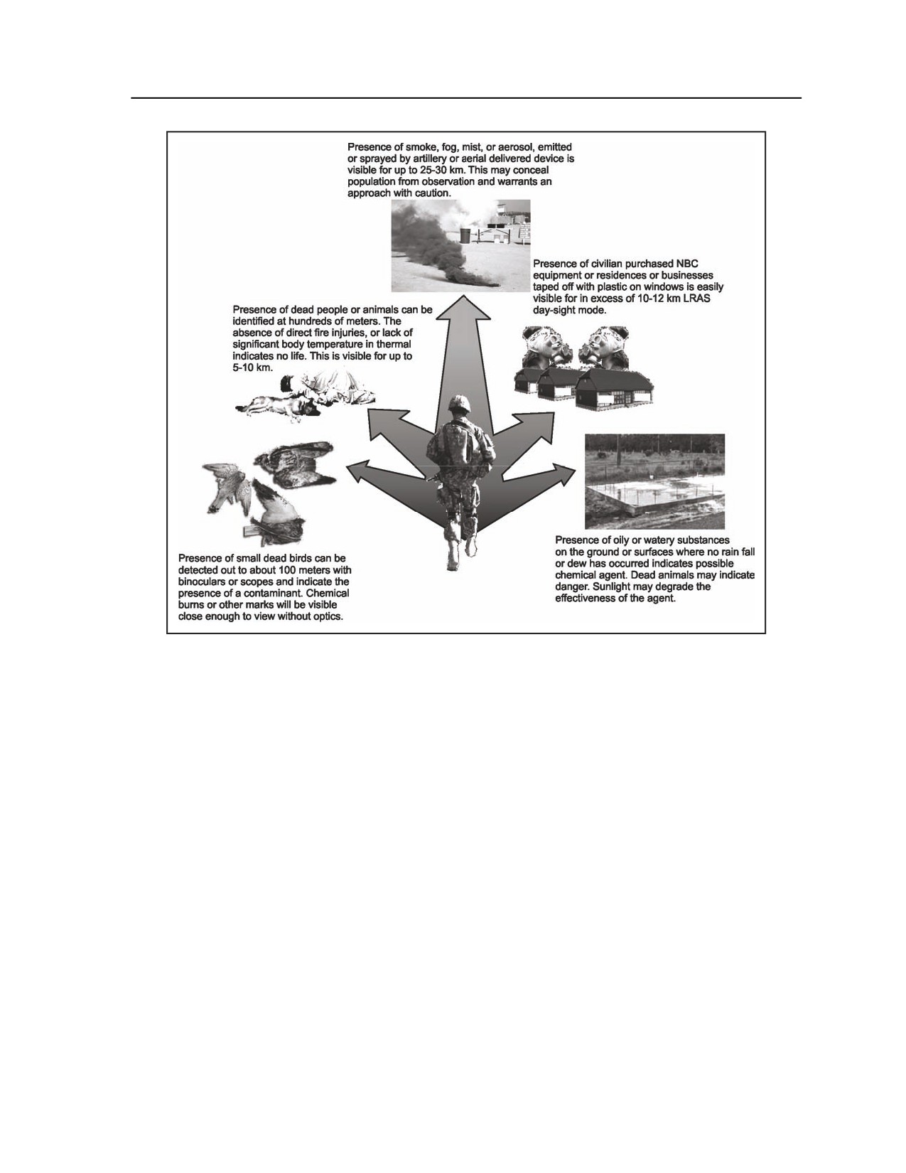
Appendix F
Figure F-1. Locating contaminants ahead of movement.
F-5. The scout section which identifies the contaminated area outside of physical contact must effectively
and quickly alert the platoon. If a CBRN encounter is deemed possible, the platoon leader should request
and plan for the use of CBRN and medical support in the platoon’s contingencies. The PSG should
similarly plan evacuation and resupply needs around a possible contaminated area. The unit SOP should
specify criteria and automatic procedures for employing detection teams and submitting the required NBC
reports following a CBRN attack or when contamination is encountered. Whenever possible, all movement
routes and future positions should be reconnoitered for CBRN contamination. Quartering party personnel
should be prepared to conduct monitoring operations; if they detect contaminated areas, they identify,
report, and mark them. The quartering party can then evaluate the location and type of hazard (nuclear
radiation or chemical/biological agent) to determine the best plan for bypassing, crossing, or operating in
the contaminated area. Based on the situation, the platoon leader and company/troop commander must be
able to implement protective measures specified in the SOP to minimize personnel losses and limit the
spread of contamination.
DEFENSIVE ACTIONS BEFORE AN ATTACK
BIOLOGICAL DEFENSE
F-6. The key protective measure against a biological attack is maintaining a high order of health, personal
hygiene, and sanitation discipline. Biological attacks are difficult to detect. If an attack occurs, the chances
of survival are better if crew members are healthy and physically fit and maintain good personal hygiene.
Keeping the body clean helps to prevent ingestion of biological agents. Small cuts or scratches should be
F-2
FM 3-20.98
3 August 2009
Chemical, Biological, Radiological, and Nuclear (CBRN) Operations
covered and kept germ-free by means of soap, water, and first-aid measures. Since insects may carry
biological agents, Soldiers should prevent insect bites by keeping clothes buttoned and skin covered. The
platoon will only consume water and food that has come through approved sources. Leadership must
ensure all Soldiers understand the risk from getting food or water from local sources.
NUCLEAR DEFENSE
F-7. The best defense against a nuclear attack is to dig in. Unit defensive positions, which range from
individual foxholes to full-scale improved fighting positions, should be prepared whenever the tactical
situation permits. Personnel should keep their individual weapons, equipment, clothing, and other issue
items in their vehicles. Inside the vehicle, equipment and any loose items must be secured because the blast
wave can turn unsecured objects into lethal missiles. Supplies, explosives, and flammable materials should
be dispersed and protected.
F-8. Reverse slopes of hills and mountains give some nuclear protection. The initial radiation and the heat
and light from the fireball of a nuclear blast tend to be absorbed by hills and mountains. The use of gullies,
ravines, ditches, natural depressions, fallen trees, and caves can also reduce nuclear casualties.
F-9. Equipment that would be damaged in the explosion must be safe guarded. One technique is not using
all night-vision goggles at the same time, if not required by the mission, to prevent damage to the image
enhancing mechanism by the flash.
CHEMICAL DEFENSE
General Guidelines
F-10. Make sure all personnel have their protective masks available, and make sure each mask fits and
functions properly. All personnel should wear the proper protective clothing in accordance with the MOPP
level designated by the commander. Inform everyone to remain alert and to be constantly aware of the
chemical threat. Protect all equipment and supplies from liquid chemical contamination by keeping them
organized and covered with a tarp. Exposed gear will not be decontaminated and will be destroyed and
deprive the platoon of its equipment. The platoon must have a standardized plan for placing M9 tape on the
vehicles as part of the early warning process.
Automatic Alarm System
F-11. The automatic alarm system is the primary means of detecting an upwind chemical attack. The
system provides two essential elements of survival: detection of a toxic agent cloud and early warning to
troops in the monitored position.
F-12. The platoon leader decides where to place the chemical alarm. In stationary operations, he first
determines the wind direction, and then places available detector units upwind of the nearest position to be
protected. The detector unit should be no more than 400 meters upwind from the alarm unit. The optimum
distance is 150 meters. Operation of the alarm can be affected by blowing sand or dust, rain, sleet, snow,
tropical conditions, and temperatures below 40 degrees Fahrenheit (4.5 degrees Celsius).
F-13. Space the available detector units approximately 300 meters apart, and make sure each detector unit
is connected to each alarm unit by telephone cable (WD-1). Position the alarm units near radiotelephone
communications; this makes it easy to alert the unit to an attack. Platoons must remember that although the
M8A1 could be installed in the platoon hot loop the new M22 cannot. Attempt to do so will cause the M43
alarm not to sound in the event of an attack.
F-14. During movement operations, the platoon should place the alarm on the exterior of the CBRN
vehicle to give the platoon as much early warning as possible.
F-15. The PSG and CBRN vehicle commander must ensure the platoon has sufficient batteries to support
continuous operation of the chemical agent alarm. The PSG also needs to ensure that normal PMCS is
being conducted on the platoons CBRN equipment and corrective action is taken when deficiencies are
identified.
3 August 2009
FM 3-20.98
F-3
Appendix F
SECTION II - MOVEMENT IN A CBRN ENVIRONMENT
F-16. As with other combat elements, one of the basic tactical requirements for the reconnaissance/scout
platoon is to be able to move through and operate in a contaminated area. To do so safely, the platoon
should follow the procedures outlined in this section.
CROSSING A CHEMICALLY OR BIOLOGICALLY CONTAMINATED
AREA
F-17. Upon identifying a contaminated area, each vehicle makes preparations to cross. While one section
provides security, the other section, positioned in a covered and concealed location, removes all externally
stowed equipment. Crews mount and test M8A1/M22 alarms and M9 paper. They adopt MOPP level 4 and
prepare the vehicle’s overpressurization system (if it is available and METT-TC factors permit). Once the
section’s preparations are complete, it moves into an overwatch position; the other section moves to a
covered and concealed position and follows the same procedures.
F-18. When both sections have been prepared, they use standard tactical movement techniques (such as
bounding overwatch) to cross the contaminated area. During this movement, the crews continuously
monitor the M8A1/M22 and the M9 paper.
F-19. Drivers and vehicle commanders take precautions to avoid low ground, overhanging branches, and
brushy areas as much as possible. While the platoon is in the contaminated area, all personnel observe each
other for signs of chemical poisoning.
F-20. Once the platoon has successfully crossed the contaminated area, it makes a temporary halt. During
the halt, detection teams monitor for the presence of chemical agents. Each crew in turn executes
operational decontamination of its vehicle and, with higher headquarters’ approval, initiates unmasking
procedures. Once these procedures are complete, the platoon continues its mission.
CROSSING A RADIOLOGICALLY CONTAMINATED AREA
F-21. The procedures involved in crossing a radiologically contaminated area are similar to those for a
chemically or biologically contaminated area, with the following additional considerations:
z
Vehicle preparation. Crews may store external equipment in the turret or cover it with a tarp.
This prevents contaminated dust particles from accumulating on the equipment. Place wet
sandbags or other materials on the turret floor to increase the amount of radiation shielding.
When available, turn on the turret overpressurization system to protect the crew compartment
from contaminated dust.
z
Movement. Vehicles should limit their speed to minimize dust. In addition, they must maintain
the correct dust interval.
z
Monitoring. Ensure IM-93/UDR-13 and VDR-2 dosimeters are zeroed (if not zeroed, follow
instructions that are included with the equipment to zero). Conduct continuous monitoring and
report the results of dosimeter and radiacmeter surveys to higher headquarters and adjacent
units.
z
Decontamination. During decontamination, each crewman should cover his nose and mouth
with a handkerchief or cloth to avoid breathing contaminated dust particles.
F-4
FM 3-20.98
3 August 2009
Appendix G
Essential Field Data
This appendix provides information that will be useful to the reconnaissance or scout
platoon’s leaders and Soldiers during execution of platoon missions. It covers tactics,
techniques, and procedures (TTP) the platoon will need to conduct an effective route
reconnaissance operation, including the tasks involved in route classification and the
inspection and classification of bridges. Also included are conversion tables to assist
in the basic computations for changing common English/American measurements to
their metric equivalents.
SECTION I - ROUTE RECONNAISSANCE SYMBOLS
G-1. Figure G-1 outlines a variety of symbols that the platoon can use to illustrate reconnaissance data on
its overlays. Figure G-2 shows symbols for various materials, facilities, equipment, and services. An
example of how these graphics are used in classification overlays is illustrated in Figure G-3, which shows
a route classification overlay. See FM 3-34.170 for additional information.
3 August 2009
FM 3-20.98
G-1
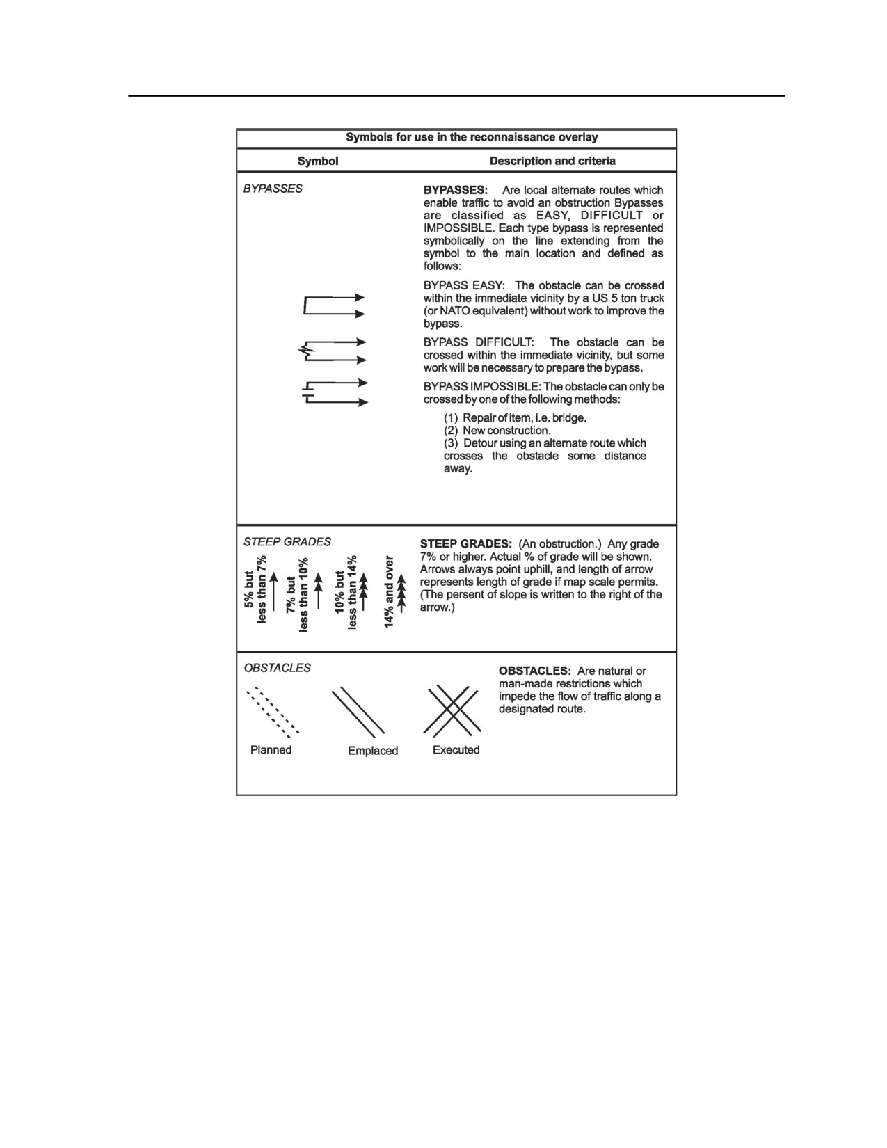
Appendix G
Figure G-1. Reconnaissance overlay symbols
G-2
FM 3-20.98
3 August 2009
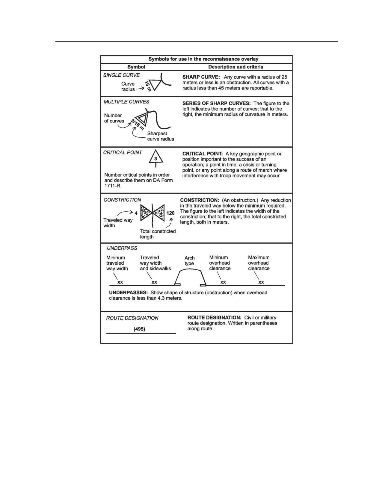
Essential Field Data
Figure G-1. Reconnaissance overlay symbols (continued)
3 August 2009
FM 3-20.98
G-3
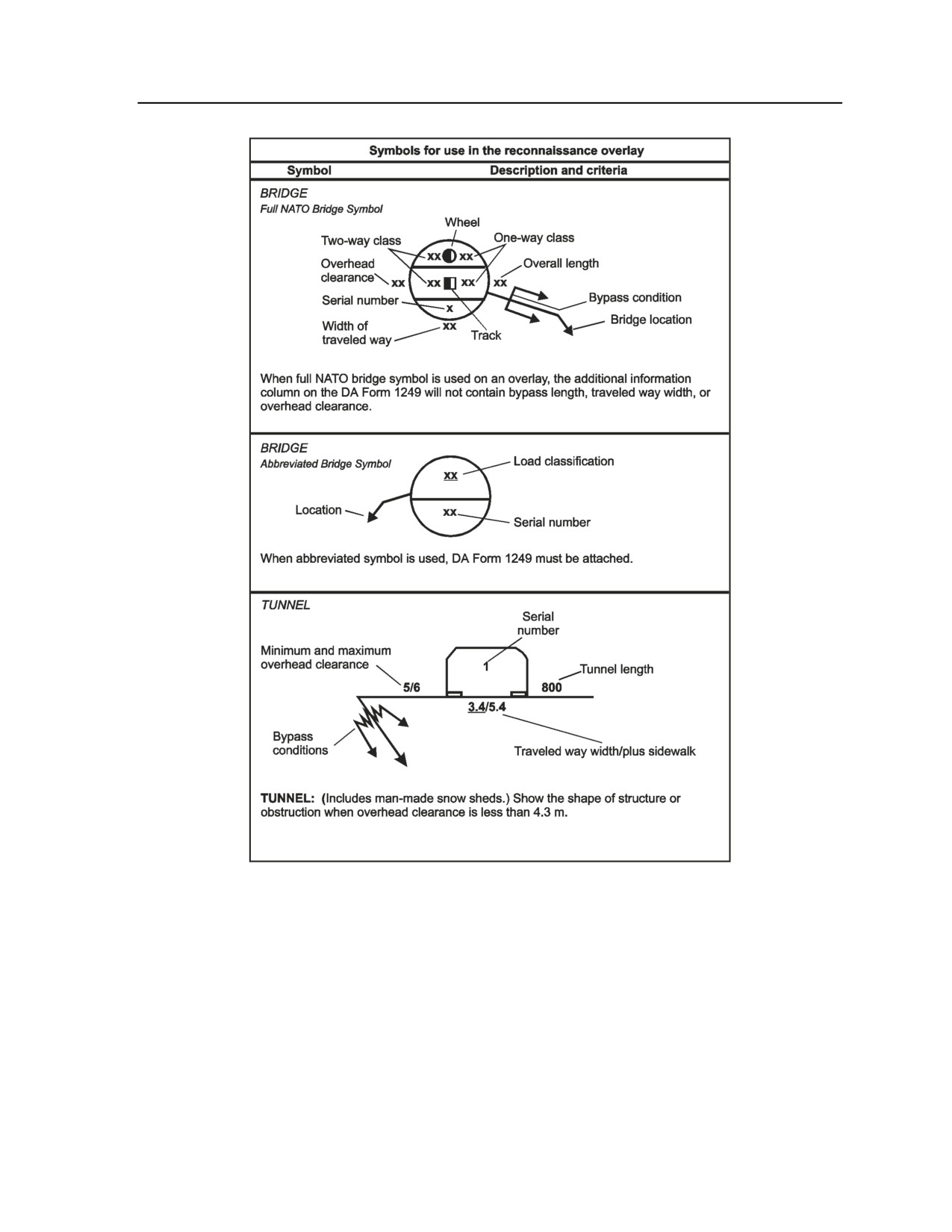
Appendix G
Figure G-1. Reconnaissance overlay symbols (continued)
G-4
FM 3-20.98
3 August 2009
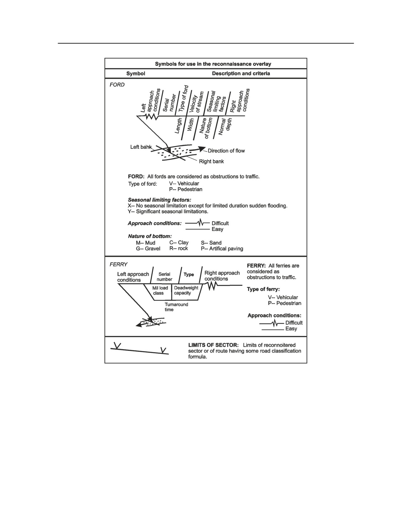
Essential Field Data
Figure G-1. Reconnaissance overlay symbols (continued)
3 August 2009
FM 3-20.98
G-5
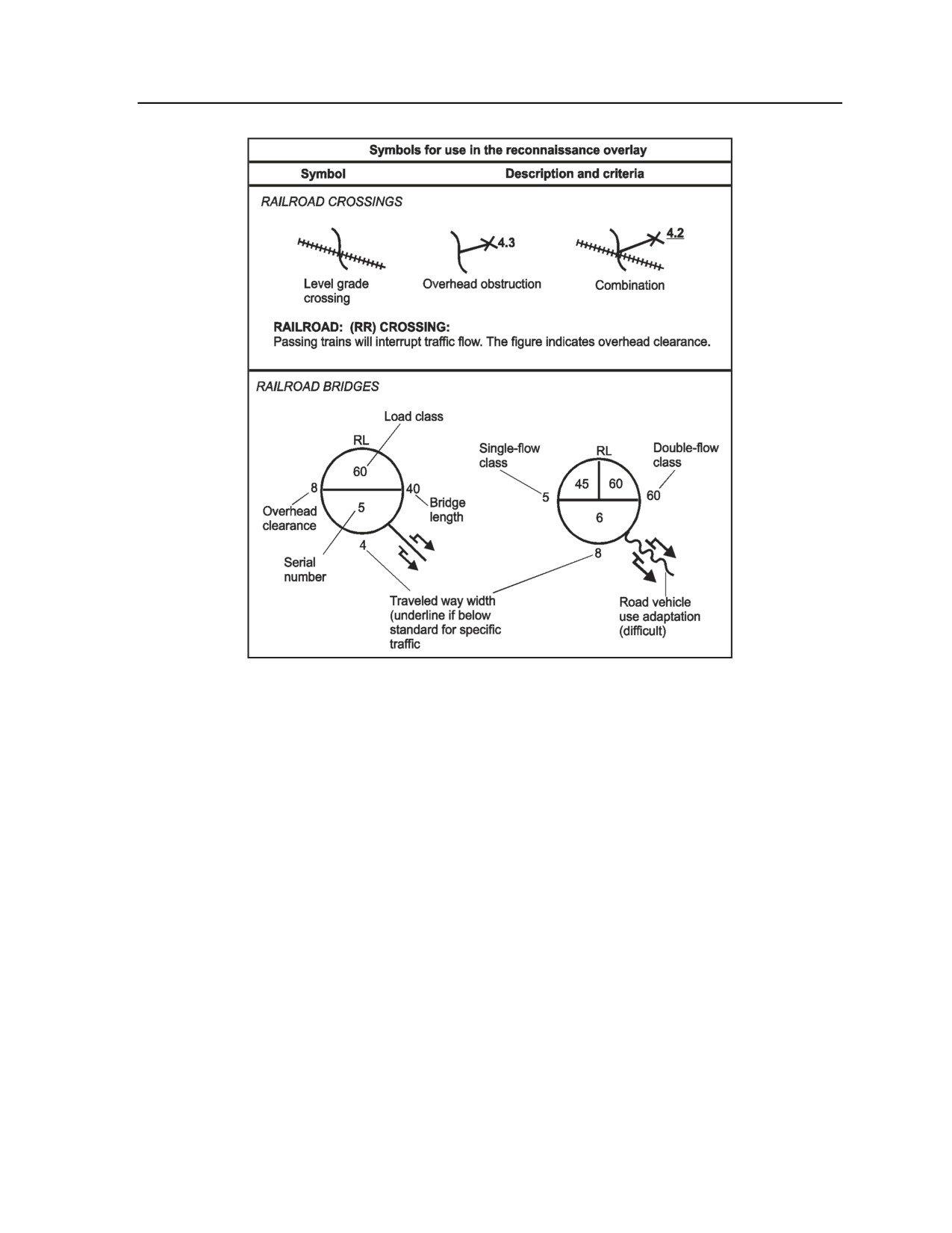
Appendix G
Figure G-1. Reconnaissance overlay symbols (continued)
G-6
FM 3-20.98
3 August 2009
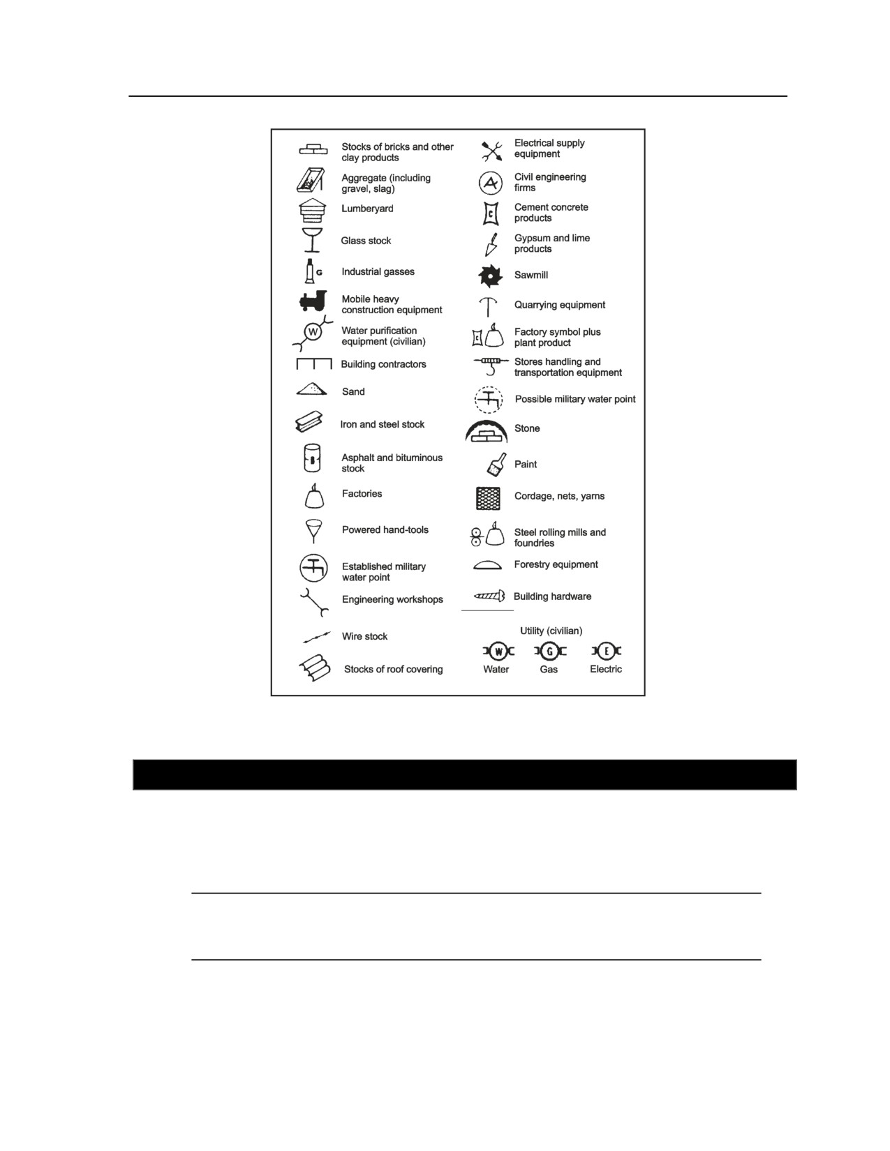
Essential Field Data
Figure G-2. Material, facility, equipment,
and service symbols
SECTION II - ROUTE CLASSIFICATION
G-2. This section describes how to perform the technical classification of a route reconnaissance. Route
classification is a tool that helps a unit determine what vehicles can travel on a particular road network and
how fast they can travel. The results of route reconnaissance are displayed on map overlays. METT-TC
conditions may dictate that only the necessary and essential facts about a route are gathered. The goal is to
assemble this information as quickly and safely as possible.
Note. This information is recorded on a route classification overlay and supplemented by
additional reports. During peacetime operations, detailed route classification missions are
performed to obtain in-depth information for future use.
3 August 2009
FM 3-20.98
G-7
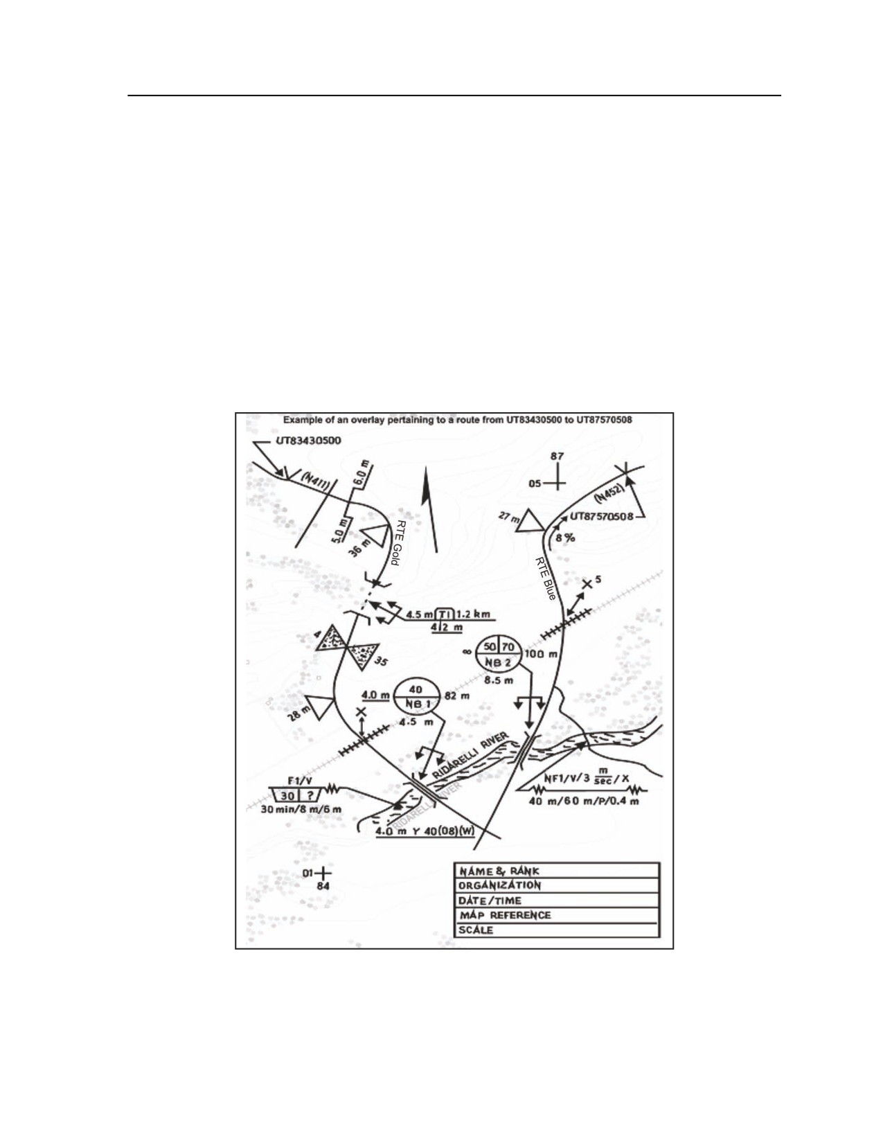
Appendix G
ROUTE CLASSIFICATION OVERLAY
G-3. The first step in understanding the technical portions of a route reconnaissance is understanding what
information is needed to complete a route classification overlay. This overlay graphically depicts a route’s
entire network of roads, bridge sites, and other key locations and terrain features.
(Note. These items are
reconnoitered, with the data recorded as support documentation for the complete route.) A route
classification gives specific details on what obstructions will slow down a convoy or maneuver force along
the route. As a minimum, the following information will be included on the route classification overlay
(see Figure G-3 for an illustration of how the information is recorded on the overlay):
z
The route classification formula.
z
The name, rank, and social security number of the person in charge of performing the
classification.
z
The unit conducting the classification.
z
The DTG showing when the classification was conducted.
z
The map name, edition, and scale.
z
Any remarks necessary to ensure complete understanding of the information on the overlay.
Figure G-3. Route classification overlay
G-8
FM 3-20.98
3 August 2009
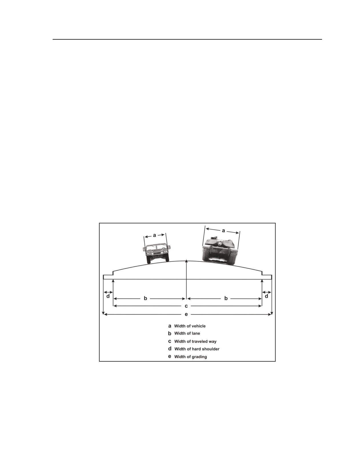
Essential Field Data
ROUTE CLASSIFICATION FORMULA
G-4. A route classification must cover the primary route (such as a road, highway, street, or trail), as well
as every alternate route on which movement can be made, to determine what type of vehicles and traffic
load each specific portion of the route can handle. Routes are classified by obtaining, through the route
reconnaissance, all pertinent information concerning trafficability and applying it to the route classification
formula. The formula, which is recorded on the route classification overlay (see Figure G-3), consists of
the following elements (an example of these items follows this listing):
z
(1) Route width, in meters.
z
(2) Route type (based on ability to withstand various types of weather conditions).
z
(3) Lowest military load classification (MLC).
z
(4) Lowest overhead clearance, in meters.
z
(5) Obstructions to traffic flow (OB), if applicable.
z
(6) Special conditions, such as snow blockage (T) or flooding (W).
Example:
(1)
(2)
(3)
(4)
(5)
(6)
5.5/
Y/
30/
4.6
(OB)
(T or W)
ROUTE WIDTH
G-5. The route width is the narrowest width of traveled way on a route (see Figure G-4). This narrow
width may be the width of a bridge, a tunnel, a road, an underpass, or other constriction that limits the
traveled way. The number of lanes is determined by the traveled-way width. The lane width normally
required for wheeled vehicles is 3.5 meters; for tracked vehicles, this width is 4 meters.
Figure G-4. Route width
G-6. Based on the number of lanes, route width is classified as follows:
z
Limited access. This type of route permits passage of isolated vehicles of appropriate width in
one direction only.
z
Single lane. A single-lane route permits use in only one direction at any one time. Passing or
movement in the opposite direction is impossible.
3 August 2009
FM 3-20.98
G-9
Appendix G
z
Single flow. This route permits the passage of a column of vehicles and allows isolated vehicles
to pass or travel in the opposite direction at predetermined points. It is preferable that such a
route be at least 1.5 lanes wide.
z
Double flow. This route permits two columns of vehicles to proceed simultaneously. It must be
at least two lanes wide.
ROUTE TYPE
G-7. The route type defines the ability of the route surface to withstand various types of weather. It is
determined for the worst section of road on the entire route and is categorized as follows:
z
Type X. This is an all-weather route that, with reasonable maintenance, is passable throughout
the year to a volume of traffic never appreciably less than its maximum capacity. This type of
route is normally formed of roads having waterproof surfaces that are only slightly affected by
rain, frost, thaw, or heat. This route is never closed because of weather effects other than snow
or flood blockage.
z
Type Y. This is a limited, all-weather route that, with reasonable maintenance, is passable
throughout the year but at times is limited to a volume of traffic considerably less than
maximum capacity. This type of route is normally formed of roads that do not have waterproof
surfaces and that are considerably affected by rain, frost, thaw, or heat. A type Y route is likely
to be closed for short periods (up to one day at a time) by adverse weather conditions, during
which heavy use of the road would probably lead to complete collapse.
z
Type Z. This type of route is passable only in fair weather. It is so seriously affected by adverse
weather conditions that it may remain closed for long periods. Improvement of a type Z route is
possible only through construction or realignment.
MILITARY LOAD CLASSIFICATION
G-8. A route’s MLC number represents its safe load-carrying capacity and indicating the maximum
vehicle class that the route can accept under normal conditions. Usually, the lowest bridge MLC
(regardless of the vehicle type or conditions of traffic flow) determines the route’s MLC. If there is no
bridge on the route, the worst section of road will determine the route’s overall classification. These are the
broad MLC categories:
z
Class 50. This is an average-traffic route.
z
Class 80. This is a heavy-traffic route.
z
Class 120. This is a very heavy-traffic route.
G-9. When a unit’s vehicles have a higher MLC than the route, its first alternative may be to seek an
alternate route. On the other hand, the unit may conduct additional reconnaissance of the roads within the
original route to determine whether a change in traffic flow (such as single-flow crossing of a weak point)
will permit heavier vehicles on the route. Whenever possible, the unit should ensure that the route network
includes a number of heavy-traffic roads as well as average-traffic roads. This helps staff planners to
manage heavy-traffic loads and to decrease the bottleneck effect.
OVERHEAD CLEARANCE
G-10. The lowest overhead clearance is the vertical distance between the road surface and any overhead
obstacle (power lines, overpasses, tunnels, and so forth) that denies the use of the road to some vehicles.
Use the infinity symbol () for unlimited clearance in the route classification formula.
(NOTE: Any point
along the route where the minimum overhead clearance is less than 4.3 meters is considered to be an
obstruction.)
Note. Platoons may deploy into regions where overhead restrictions are already calculated and
posted for civilian traffic.
G-10
FM 3-20.98
3 August 2009
Essential Field Data
ROUTE OBSTRUCTIONS
G-11. Route obstructions restrict the type, amount, or speed of traffic flow. They are indicated in the route
classification formula by the abbreviation
“OB.” The platoon must depict the exact nature of each
obstruction it encounters on the route classification overlay.
G-12. Specific types of obstructions that the platoon may face on a route include the following:
z
Overhead obstructions with a clearance of less than 4.3 meters. Examples include tunnels,
underpasses, overhead wires, and overhanging buildings.
z
Reductions in traveled-way widths that are below the standard minimums prescribed for the type
of traffic flow (see Table G-1 for examples). This category includes reductions caused by
bridges, tunnels, craters, lanes through mined areas, projecting buildings, or rubble.
z
Slopes (gradients) of 7 percent or greater.
z
Curves with a radius of 25 meters or less. Curves with a radius between 25.1 and 45 meters are
not considered obstructions, but they must be recorded on the route reconnaissance overlay.
z
Ferries.
z
Fords.
Table G-1. Traffic-flow capability based on route width
Limited
Single
Single
Double
Access
Lane
Flow
Flow
Wheeled vehicles
At least 3.5 m
3.5 to 5.5 m
5.5 to 7.3 m
Over 7.3 m
Tracked and
At least 4.0 m
4.0 to 6.0 m
6.0 to 8.0 m
Over 8 m
combination vehicles
SNOW BLOCKAGE AND FLOODING
G-13. In cases where snow blockage is serious and is blocking traffic on a regular and recurrent basis, the
symbol used in the route classification formula is “T.” When flooding is serious and is blocking traffic on a
regular and recurrent basis, the symbol in the route classification formula is “W.”
EXAMPLES OF ROUTE CLASSIFICATION FORMULA
G-14. The following are examples illustrating the use of the route classification formula:
z
6.1m/Z/40/∞. This is a fair-weather route (type Z) with a minimum traveled way of 6.1 meters,
and an MLC of 40. Overhead clearance is unlimited (). There are no obstructions to traffic
flow. Based on its minimum traveled-way width, this route accommodates both wheeled and
tracked, single-flow traffic without obstruction.
z
6.1m/Z/40/∞(OB). This formula indicates a fair-weather route (type Z) similar to the previous
example, except that there is an obstruction. This obstruction could consist of overhead
clearances of less than 4.3 meters, grades of 7 percent or greater, curves with a radius of 25
meters and less, or fords and ferries. A traveled way of 6.1 meters limits this route to one-way
traffic if there is no width obstruction. If the route is used for double-flow traffic, 6.1 meters of
traveled way is considered an obstruction and is indicated in the formula as an obstruction.
z
7m/Y/50/4.6(OB). This limited, all-weather route (type Y) has a minimum traveled way of 7
meters, an MLC of 50, an overhead clearance of 4.6 meters, and an obstruction. This route width
is not suitable for double-flow traffic (wheeled or tracked). This width constriction is indicated
as OB in the route classification formula if the route is intended to be used for double-flow
traffic.
z
10.5m/X/120/∞(OB)(W). This formula shows an all-weather route (type X) with a minimum
traveled-way width of 10.5 meters, which is suitable for two-way traffic of both wheeled and
tracked vehicles. The route has an MLC of 120, unlimited overhead clearance, an obstruction,
and regular, recurrent flooding.
3 August 2009
FM 3-20.98
G-11
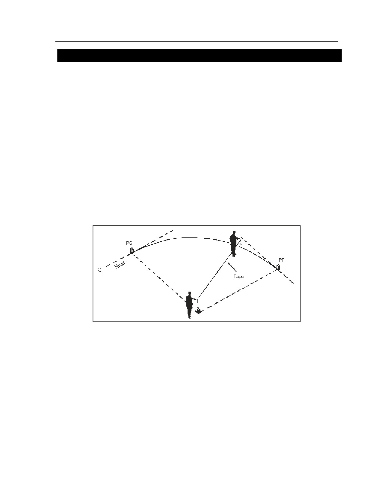
Appendix G
SECTION III - CURVE CALCULATIONS
G-15. The speed at which vehicles move along a route is affected by sharp curves. Curves with a radius of
25 meters and less are obstructions to traffic and are indicated by the abbreviation “OB” in the route
classification formula. Curves with a radius between 25.1 and 45 meters are recorded on the overlay but
are not considered obstructions.
MEASURING METHODS
G-16. The platoon can use several methods to measure curves:
z
Tape measure.
z
Triangulation.
z
Formula.
TAPE MEASURE METHOD
G-17. A quick way to estimate the radius of a sharp curve is by using a tape measure to find the radius (see
Figure G-5). Imagine the outer edge of the curve as the outer edge of a circle. Find (estimate) the center of
this imaginary circle; then measure the radius using a tape measure. Start from the center of the circle and
measure to the outside edge of the curve. The length of the tape measure from the center of the imaginary
circle to its outer edge is the curve’s radius. This method is practical for curves located on relatively flat
ground and having a radius of up to 15 meters.
Figure G-5. Tape measure method
TRIANGULATION METHOD
G-18. Determine a curve’s approximate radius by “laying out” right triangles (3:4:5 proportion) at the
point of curvature (PC) and point of tangency (PT) locations (see Figure G-6). The intersection (o), which
is formed by extending the legs of each triangle, represents the center of the circle. The distance (R) from
point o to either point PC or PT represents the curve’s radius.
G-12
FM 3-20.98
3 August 2009
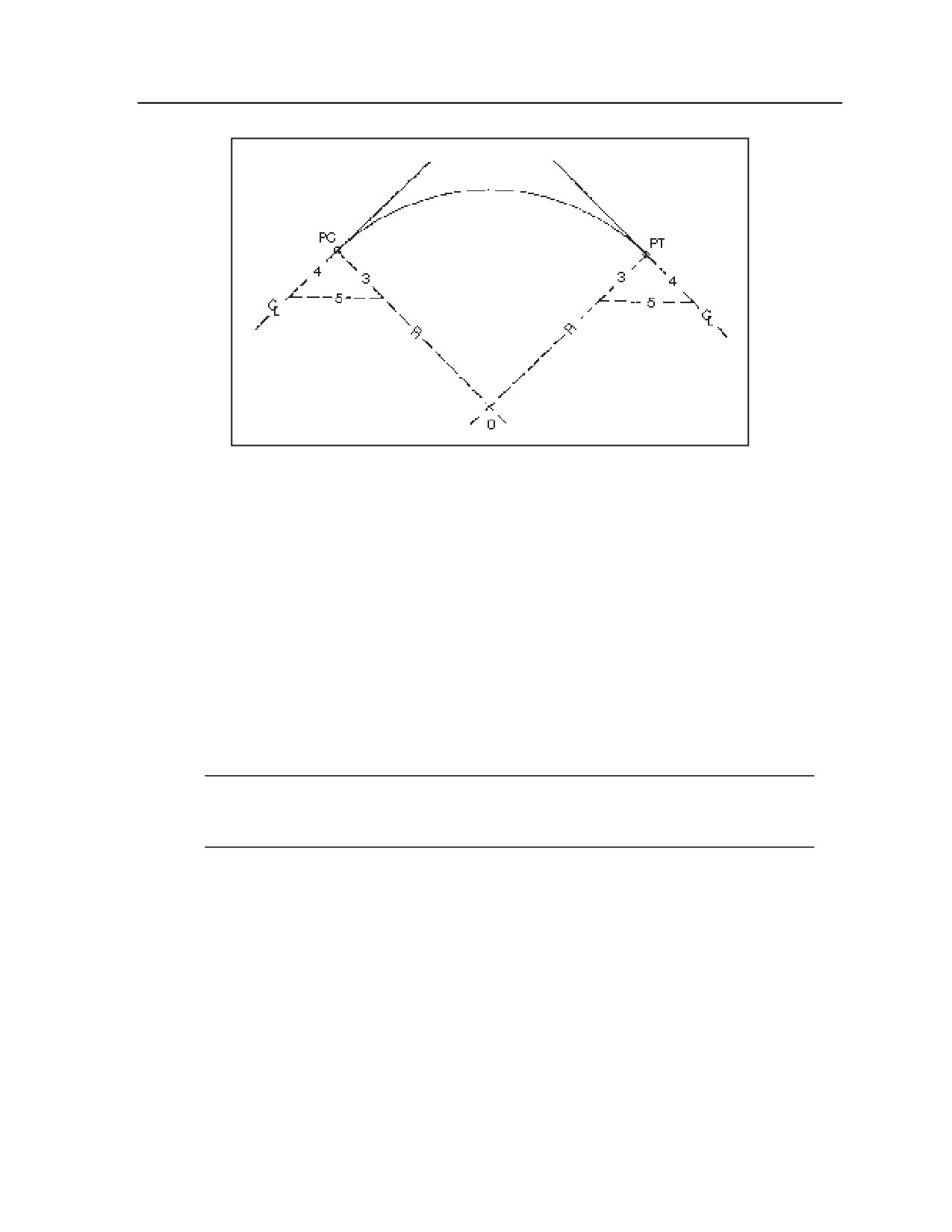
Essential Field Data
Figure G-6. Triangulation method
FORMULA METHOD
G-19. This method of determining the curve’s radius (illustrated in Figure G-7) is based on the following
formula (all measurements are in meters):
R = (C2/8M) + (M/2)
R = radius of the curve.
C = the distance from the centerline of the road to the centerline of the road at the outer extremities
of the curve.
M = the perpendicular distance from the center of the tape to the centerline of the road.
G-20. Example: If C is 15 meters and M is fixed at 2 meters, the formula becomes the following:
R = (152/16) + 2/2 = 15.0625
G-21. The result of this calculation (a radius of slightly more than 15 meters) would be an obstruction to
traffic flow, and “OB” would be entered in the route classification formula.
Note: When conditions warrant, set M at 2 meters from the centerline, then measure C 2 meters
from the centerline. Use this method when there is a time limitation or when natural or man-
made restrictions prevent proper measurements.
3 August 2009
FM 3-20.98
G-13
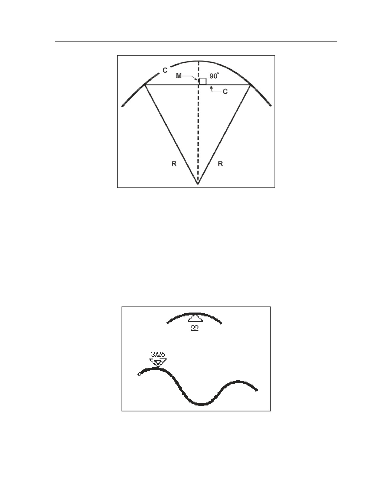
Appendix G
Figure G-7. Formula method
CURVE SYMBOL
G-22. Sharp curves with a radius of 45 meters or less are symbolically represented on maps or overlays by
a triangle that points to the curve’s exact map location. In addition, the measured value (in meters) for the
radius of curvature is written outside the triangle (as shown in the top drawing in Figure G-8). All curves
with a radius of 45 meters or less are reportable.
SERIES OF SHARP CURVES
G-23. A series of sharp curves is represented by two triangles, one drawn inside the other. The outer
triangle points to the location of the first curve. The number of curves and the radius of curvature for the
sharpest curve in the series are written to the outside of the triangle (bottom drawing in Figure G-8).
Figure G-8. Curve symbols
G-14
FM 3-20.98
3 August 2009
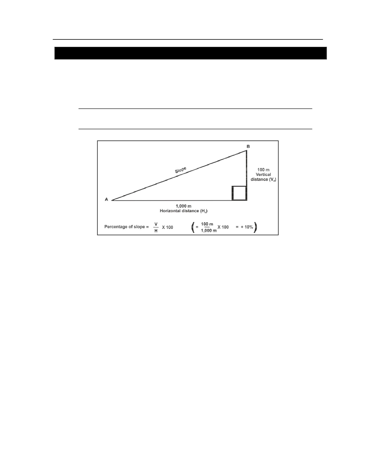
Essential Field Data
SECTION IV - SLOPE ESTIMATION
G-24. The rise and fall of the ground is known as the slope or gradient (grade). The percentage of the slope
is used to describe the effect that inclines have on movement rates. It is the ratio of the change in elevation
(the vertical distance divided by the horizontal ground distance) multiplied by 100 (see Figure G-9). It is
important to express the vertical distance and the horizontal distance in the same unit of measure. Slopes of
7 percent or greater affect the platoon’s movement speed along a route and are considered an obstruction.
Record all slopes greater than 5 percent on the route classification overlay.
Note. Platoons may deploy into regions where percent of slope on major roads and routes is
already calculated and posted.
Figure G-9. Formula for slope percentage
SLOPE PERCENTAGE
G-25. The following discussion focuses on four methods for determining the percent of slope.
CLINOMETER METHOD
G-26. A clinometer is an instrument that directly measures percent of slope. Typically, the clinometer is
found in engineer survey units as part of an artillery compass and as part of an engineer platoon sketch set.
Follow the instructions included with the instrument. Scouts in CFV equipped platoons are equipped with a
vehicle slope indicator in the turret which will provide a rough percent of slope. This instrument also
provides clear to fire information to crew during TOW missile engagements.
PACE METHOD
G-27. The pace method is a quick way to estimate percent of slope. The first step in using this method is to
accurately determine the height and pace of each Soldier of a reconnaissance team. As a rule of thumb, the
eye level of the average Soldier is 1.75 meters above the ground. The pace of the average Soldier is 0.75
meter. Determine the percent of slope using these steps:
z
Stand at the bottom of the slope with head and eyes level.
z
Sight a spot on the slope. This spot should be easily identifiable. If it is not, another member of
the team should go forward to mark the location.
z
Walk forward and stand on the marked spot. Record the number of paces. Repeat this procedure
until you reach the top of the slope (estimate fractions of an eye level).
3 August 2009
FM 3-20.98
G-15
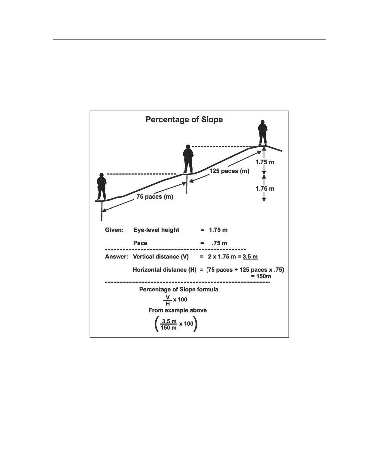
Appendix G
z
Compute the vertical distance by multiplying the number of sightings by the eye-level height
(1.75 meters). Compute the horizontal distance by totaling the number of paces and converting
them to meters by multiplying by 0.75 (or the known pace-to-meter conversion factor).
z
Calculate the percent of slope by substituting the values into the percent-of-slope formula (see
Figure G-10). Because this method considers horizontal ground distance and incline distance as
equal, you can obtain reasonable accuracy only for slopes of less than 30 percent. This method
requires practice to achieve acceptable accuracy. A line level and string can be used to train this
method.
Figure G-10. Pace method for percent of slope
MAP METHOD
G-28. The platoon can use a large-scale map (such as 1:50,000) to estimate the percent of slope quickly.
After identifying the slope on the map, find the difference in elevations between the top and bottom of the
slope by reading the elevation contours or spot elevation; then measure and convert the horizontal distance
(usually road distance) to the same unit of measurement as the elevation difference. Substitute the vertical
and horizontal distances in the percent-of-slope formula as shown in Figure G-11.
G-16
FM 3-20.98
3 August 2009
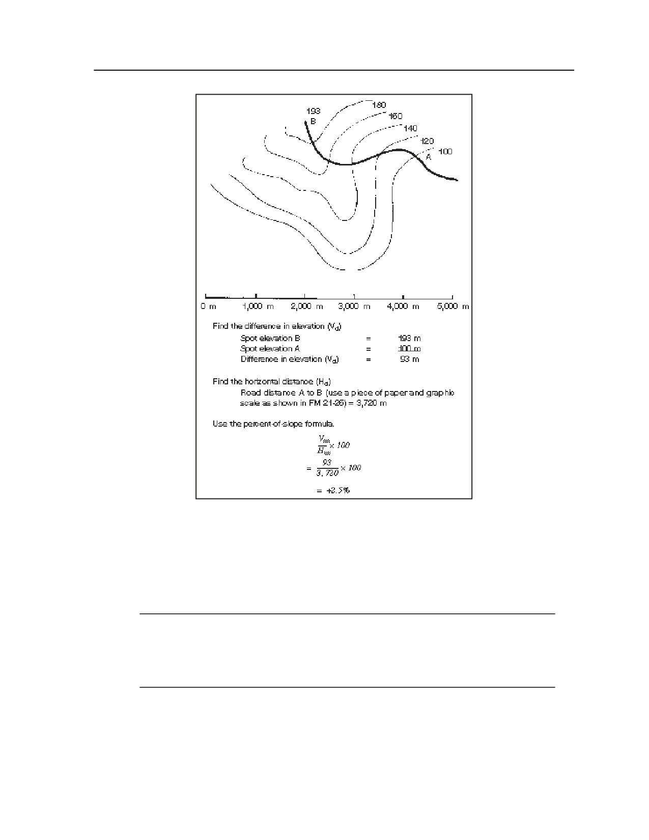
Essential Field Data
Figure G-11. Map method for percent of slope
ANGLE OF SLOPE METHOD
G-29. The angle of slope method is a quick way to estimate the percent of slope. The angle of slope is first
measured by using an elevation quadrant, aiming circle, M2 compass, or binoculars with a standard reticle.
If the instrument used to take the angle of measurement is mounted above ground level, the sighting must
be taken a corresponding, and equal, distance higher on the slope to compensate for the height difference.
Note. This corresponding distance is the height of the instrument above the ground. You must
take the angle of measurement at the base of the slope. Once you obtain the angle of
measurement, consult Table G-2 and enter the column corresponding to the measured angle of
slope. You can then read the percent of slope directly from the table. Figure G-12 illustrates this
method.
3 August 2009
FM 3-20.98
G-17
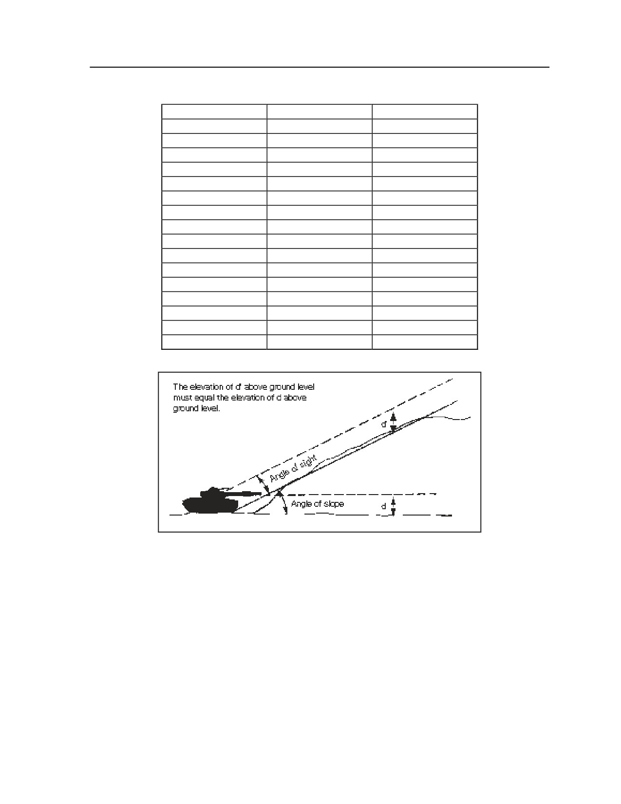
Appendix G
Table G-2. Conversion of degrees and mils to percent of slope
DEGREES OF SLOPE
MILS OF SLOPE
PERCENT OF SLOPE
1
18
1.7
2
36
3.5
3
53
5.2
4
71
7.0
5
89
8.7
10
175
17.6
15
267
26.7
20
356
36.4
25
444
46.6
30
533
57.7
35
622
70.0
40
711
83.9
45
800
100.0
50
889
108.7
55
978
117.6
60
1,067
126.7
Figure G-12. Angle of slope method for percent of slope
SLOPE SYMBOL
G-30. Most vehicles will be slowed when they must negotiate slopes of 7 percent or greater for a
significant distance. Such slope characteristics must be accurately reported. The symbols illustrated in
Figure G-13 are used to represent various slope percentages.
G-18
FM 3-20.98
3 August 2009
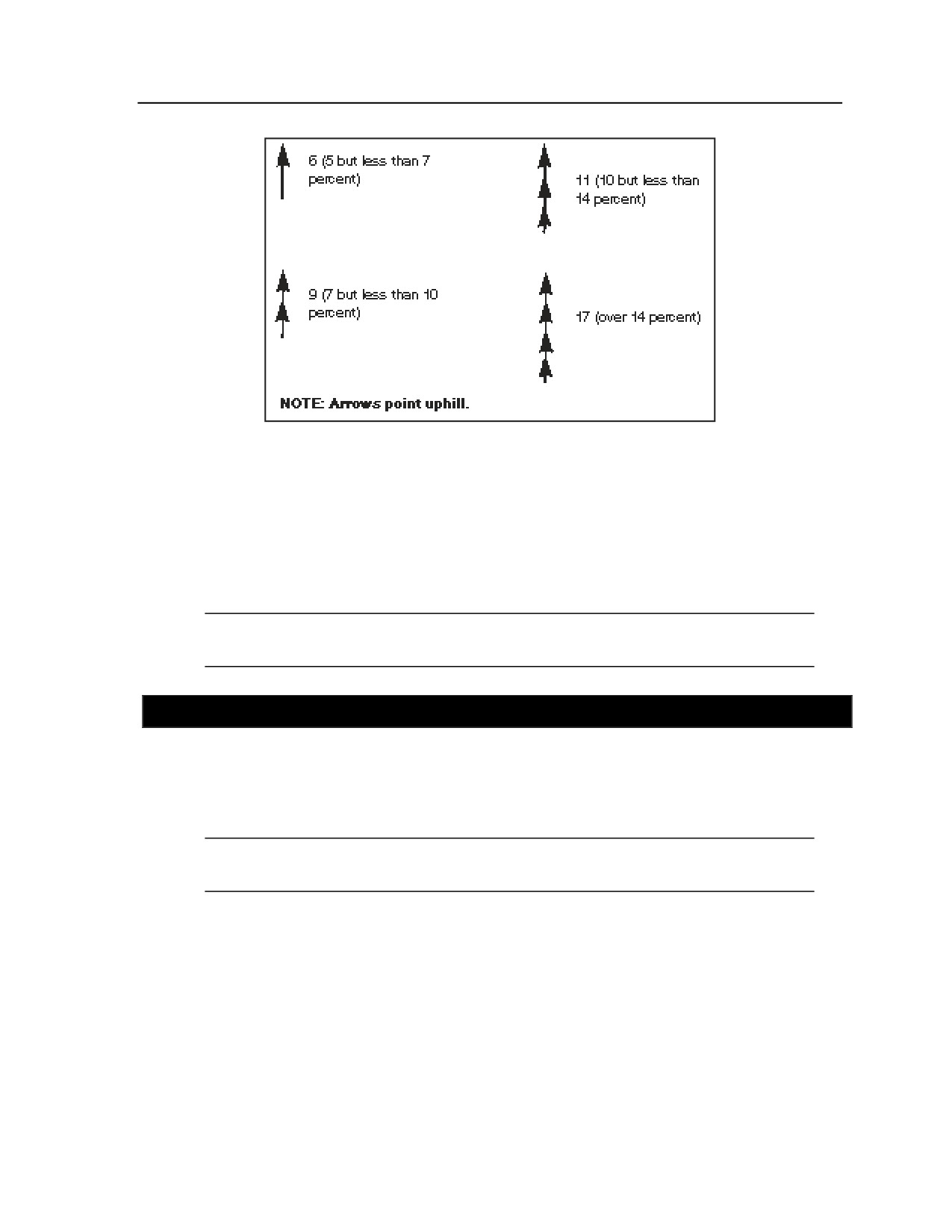
Essential Field Data
Figure G-13. Percent-of-slope symbols
G-31. A single arrowhead along the trace of a route pointing in the uphill direction indicates a grade of at
least 5 percent but less than 7 percent. Two arrowheads represent a grade of at least 7 percent but less than
10 percent. Three arrowheads represent a grade of at least 10 percent but less than 14 percent. Four
arrowheads represent a grade of 14 percent or more. As noted previously, no symbol is required for slopes
of less than 5 percent.
G-32. The percent of slope is written to the right of the arrow. When the map scale permits, the length of
the arrow shaft will be drawn to map scale to represent the approximate length of the grade.
Note. Slopes of 7 percent or greater are obstructions to traffic flow and are indicated by the
abbreviation “OB” in the route classification formula.
SECTION V - CONSTRICTIONS
G-33. Reductions in the traveled-way width, known as constrictions, include narrow streets in built-up
areas, drainage ditches, embankments, and war damage. Constrictions may limit vehicle movement;
therefore, the physical dimensions of the vehicles that will be using the route must be known and
considered when conducting the route classification. Reconnaissance or scout platoons should know
dimensions of the vehicles with in their brigade elements.
Note. Platoons may deploy into regions where constrictions on most roads and routes is already
calculated and posted for civilian traffic.
CONSTRICTION SYMBOL
G-34. Constrictions that reduce the traveled-way width to below minimum requirements are depicted on
maps and overlays by two opposing shaded triangles. The width of the usable traveled way (in meters) is
written next to the left triangle. The length of the constriction (in meters) is written next to the right triangle
(see Figure G-14).
3 August 2009
FM 3-20.98
G-19
Appendix G
Figure G-14. Route constriction symbol
Note. Constrictions of traveled-way widths below the minimum standard for the type and flow
of traffic are obstructions; they are indicated by the symbol “OB” in the route classification
formula.
UNDERPASSES
G-35. An underpass is depicted on a map or overlay by a symbol that depicts the structure’s ceiling. The
symbol is drawn over the route at the map location of the underpass. The width (in meters) is written to the
left of the underpass symbol, and the overhead clearance (in meters) is written to the right of the underpass
symbol (see Figure G-15).
Figure G-15. Underpass symbols
G-20
FM 3-20.98
3 August 2009
Essential Field Data
G-36. If sidewalks permit emergency passage of wider vehicles, the sidewalks are symbolically
represented. The traveled-way width is recorded first, followed by a slash, then the structure’s total width,
including sidewalks.
Note. Features that result in a decrease in overhead clearance, such as arched ceilings or
irregularities in ceilings, must be noted. In such cases, an extension of width does not
necessarily mean that the structure will accommodate wider vehicles.
G-37. Both minimum and maximum overhead clearances, if different, will be recorded. The minimum will
be recorded first, followed by a slash, then the maximum overhead clearance.
TUNNELS
G-38. A tunnel is a section of roadway along the route that is either artificially covered (such as a covered
bridge or a snowshed) or underground. A tunnel classification determines essential information such as the
serial number, location, type, length, width (including sidewalks), bypasses, alignment, gradient, and cross
section. A tunnel consists of a bore, a tunnel liner, and a portal.
TUNNEL BORE TYPES
G-39. Common shapes of tunnel bores are semicircular, elliptical, horseshoe, and square with an arched
ceiling (see Figure G-16).
Figure G-16. Types of tunnel bores
TUNNEL SYMBOL
G-40. Basic tunnel information is recorded on maps or overlays using symbols (as shown in Figure G-17).
The location of the tunnel entrance is shown by an arrow from the symbol to the location of the entrance.
For long tunnels (more than 30.5 meters), both tunnel entrance locations are indicated.
G-41. For later reference purposes, each tunnel on a particular map or overlay is assigned a serial number.
3 August 2009
FM 3-20.98
G-21
Appendix G
Note. Check for an existing fixed serial number on the actual tunnel or map sheet; if there is no
serial number, assign a number based on unit SOP. Serial numbers are not duplicated on any one
map sheet, overlay, or document. The number is recorded inside the symbol. The traveled-way
width is shown in meters and is recorded below the symbol.
Figure G-17. Tunnel symbols
G-42. If sidewalks permit the emergency passage of wider vehicles, they are symbolically represented. The
traveled-way width is written first, followed by a slash, then the total width including the sidewalks.
Note. Structures with arched or irregular ceilings will decrease overhead clearance. An
extension of width does not necessarily mean that the structure will accommodate wider
vehicles.
OVERHEAD CLEARANCE
G-43. Overhead clearance is the shortest distance between the surface of a traveled way and any
obstruction vertically above it. The measurement of overhead clearance must be accurate. Figures G-18
and G-19 show methods and considerations for obtaining these measurements.
G-22
FM 3-20.98
3 August 2009
Essential Field Data
Figure G-18. Overhead clearance measurements
Figure G-19. Overhead clearance in tunnels
SECTION VI - STREAM CLASSIFICATION
G-44. A stream crossing site is a location at a body of water where vehicles can “swim” across and not
touch the bottom. Identify and report locations that permit smooth traffic flow and reduce route
obstructions as much as possible. When conducting reconnaissance of a stream crossing area, record the
stream’s depth, width, approaches, velocities, and natural and man-made obstacles (see Figure G-20).
3 August 2009
FM 3-20.98
G-23
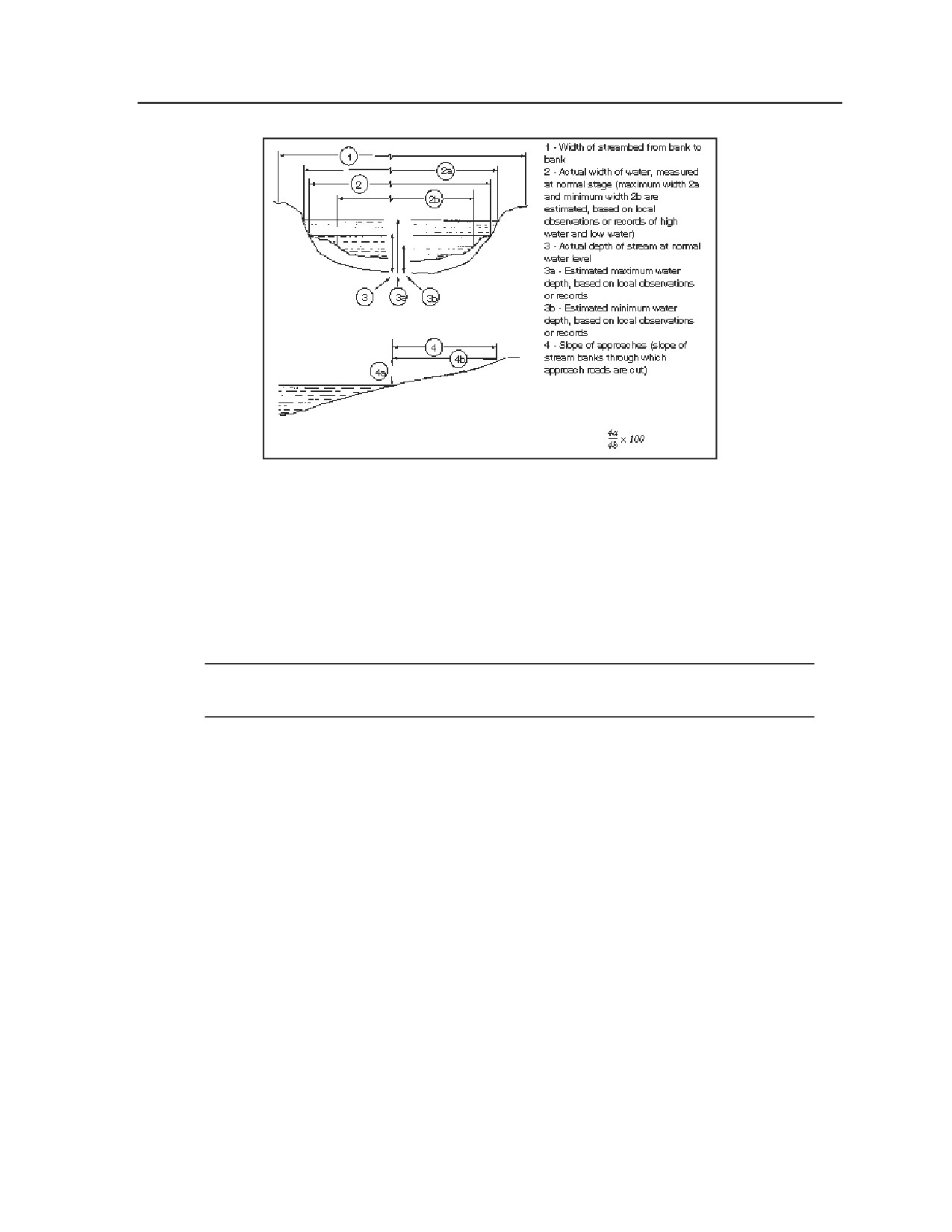
Appendix G
Figure G-20. Dimensions required for streams
MEASUREMENTS
G-45. Stream depth is usually measured using field-expedient devices such as poles or weighted ropes.
Measure the depth every 3 meters along the planned stream crossing route. Recheck depths and currents
frequently during inclement weather. Sudden, heavy rainfall may turn a sluggish stream or river into a
torrent very quickly, particularly in tropical and arid regions. Monitor weather reports of the surrounding
area. Storms occurring miles away can cause flash flooding. Always consider the importance of upstream
dams and locks that may cause elevated levels or flooding when opened or destroyed.
Note. When there is little time for reconnaissance, the actual measured depth should be
recorded as the normal depth.
PREEXISTING DATA
G-46. In developed areas of the world, special water navigation maps containing data on specific bodies of
water are available through government agencies. The S2 can obtain copies of such maps. When using
these maps, however, check the actual site whenever possible; there is no substitute for in-person
reconnaissance.
STREAM WIDTH
G-47. Determine stream width using one of several available methods: the compass method; an aiming
circle, azimuth indicator, or alidade; the GPS; or a direct measurement.
COMPASS METHOD
G-48. In this method, use a compass to take an azimuth from a point on the near shore, close to the water’s
edge, to a point on the opposite shore, also close to the water’s edge (as illustrated in Figure G-21). On the
near shore, establish another point that is on a line with and at a right angle to the azimuth selected. The
azimuth to the same point on the far shore is + or - 45 degrees (800 mils) from the previous azimuth.
Measure the distance between the two points on the near shore. This distance is equal to the distance across
the stream.
G-24
FM 3-20.98
3 August 2009
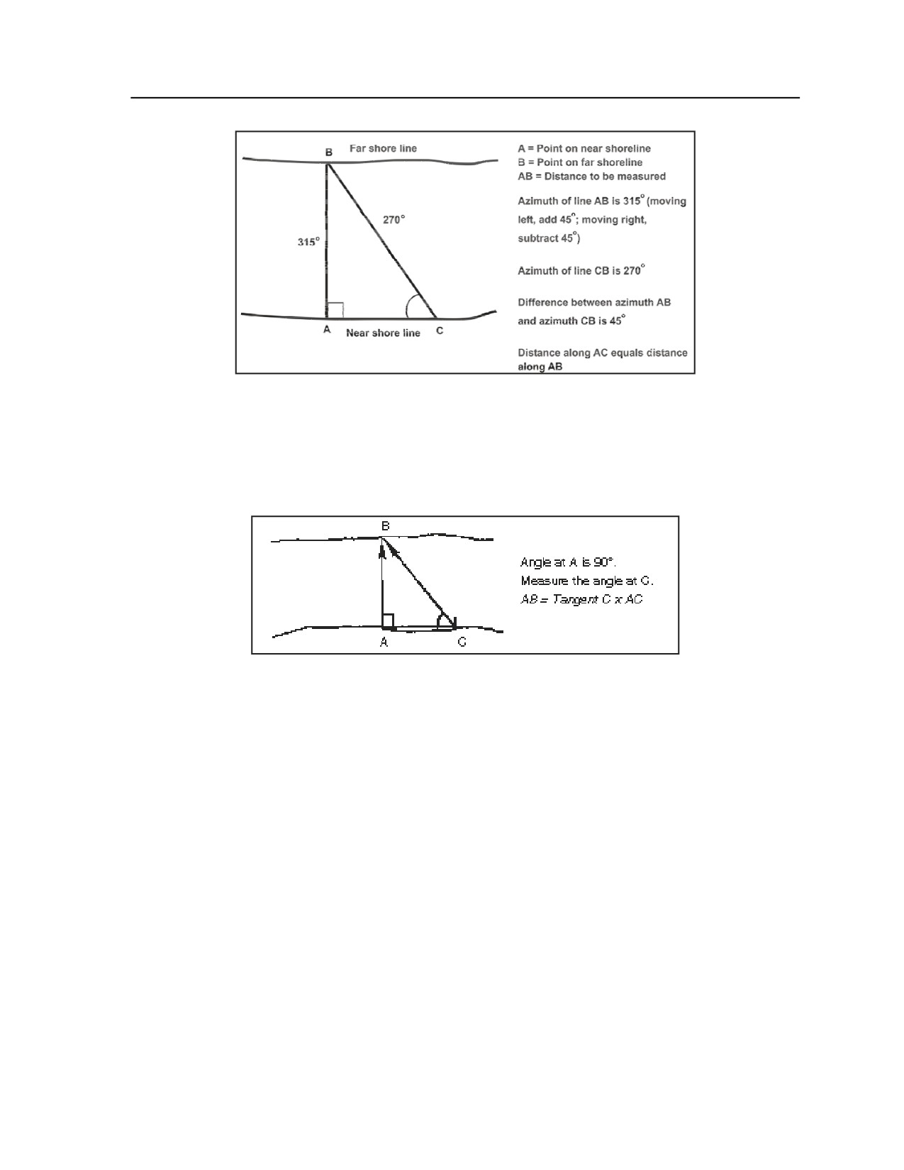
Essential Field Data
Figure G-21. Measuring stream width with a compass
AIMING CIRCLE, AZIMUTH INDICATOR, OR ALIDADE
G-49. Use an aiming circle, azimuth indicator, or alidade to measure the angle between two points that are
a known distance apart on the near shore and a third point directly across the river from one of these points
(see Figure G-22). Using trigonometric relationships, compute the distance across the stream.
Figure G-22. Measuring stream width
with a surveying instrument
GLOBAL POSITIONING SYSTEM
G-50. In this method, calculate the distance using two known grid points taken from the GPS.
DIRECT MEASUREMENT
G-51. Measure short gaps with a tape measure or a dark rope that is accurately measured and marked.
CURRENT VELOCITY
G-52. Current velocity varies in different parts of a stream. Velocity is usually slower near the shore and
faster in the main channel. Perform the following procedure to determine stream velocity:
z
Measure a distance along a riverbank.
z
Throw a light, floating object (not affected by the wind) into the stream.
z
Record the time it takes for the object to travel the measured distance. Repeat the procedure at
least three times. Use the average time of the test in the following formula (also illustrated in
Figure G-23) to determine the stream’s velocity:
Stream velocity (in meters per second) =
measured distance (in meters) divided by
average time (in seconds)
3 August 2009
FM 3-20.98
G-25
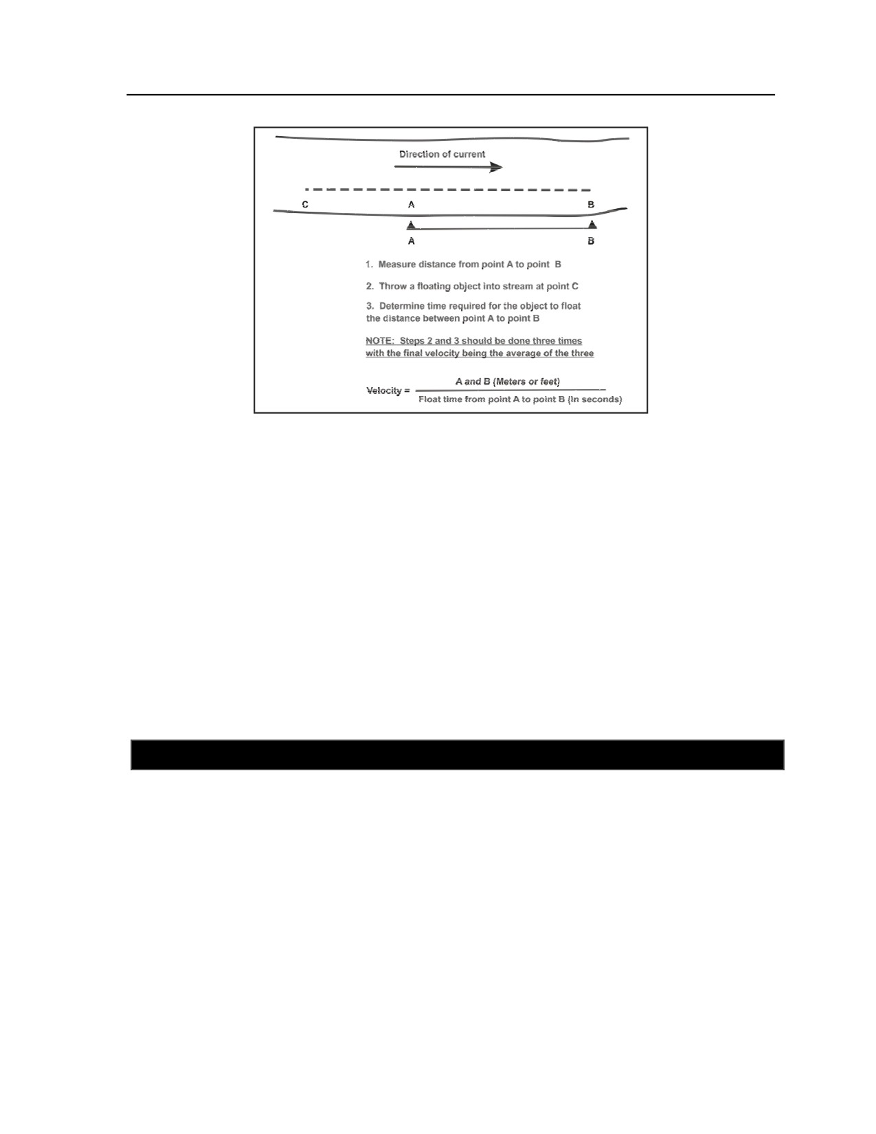
Appendix G
Figure G-23. Measuring stream velocity
STREAM APPROACHES
G-53. Gently sloping stream approaches are desirable for fording and swimming operations. Slope is
expressed in percentage. Slope-climbing capability must be considered for the vehicles that are expected to
ford/swim the stream. This information is found on the vehicle’s data plate or dash plate or in the vehicle’s
technical manual (TM). When considering slope-climbing capability, consider the degrading effects of
weather, the condition of the vehicle’s tires or tracks, and the condition of the ground surface of both sides
of the stream.
G-54. The platoon should avoid the following obstacles during stream crossing operations:
z
High, vertical banks.
z
Mines and booby traps that are located at the entrance and exit points or at likely approaches to
the stream; that are submerged in the stream itself; or that are attached to poles or floating logs.
z
Debris and floating objects such as logs and brush, poles, or floating objects with wire attached
that could foul propellers and suspension systems.
z
Ice crusts.
SECTION VII - FORD CLASSIFICATION
G-55. A ford is a location in a water barrier where the current, bottom, and approaches allow personnel,
vehicles, and other equipment to cross while remaining in contact with the bottom during the crossing.
Fords are obstructions to traffic flow and are shown by the abbreviation “OB” in the route classification
formula.
G-56. During high-water periods, low-water bridges are easily confused with paved fords because both are
completely submerged. It is important to know the difference between this type of bridge and a paved ford
because of corresponding military load limitations.
G-57. Fords are classified according to their crossing potential (or trafficability) for pedestrians or vehicles.
Fordable depths for vehicular traffic can be increased by providing suitable waterproofing and by adding
deep-water fording kits. These kits permit fording depths up to an average of 4.3 meters. Check vehicle
TMs for further fording information.
G-58. Record the composition of the approaches. They may be paved or covered with mat or track
materials, but they are usually unimproved. The composition and the slope of the approaches to a ford
G-26
FM 3-20.98
3 August 2009
Essential Field Data
should be carefully noted to determine the trafficability after fording vehicles saturate the surface material
of the approaches. Identify the ford’s left and right approaches when looking downstream.
G-59. Record the current velocity and the presence of debris to determine their effect, if any, on the ford’s
condition and trafficability. Estimate the current velocity using the following categories:
z
Swift (more than 1.5 meters per second).
z
Moderate (1 to 1.5 meters per second).
z
Slow (less than 1 meter per second).
G-60. The composition of the ford’s stream bottom largely determines its trafficability. It is important to
determine whether the bottom is composed of sand, gravel, silt, clay, or rock and in what proportions.
Record whether the ford’s natural river bottom has been improved to increase the load-bearing capacity or
to reduce the water depth. Improved fords may have gravel, macadam, or concrete surfacing; layers of
sandbags; metal screening or matting; or timber (corduroy) planking. Determine if material is available
nearby that can be used to improve the ford. Record limited ford information, such as the following, on
maps or overlays using symbols as illustrated in Figure G-24:
z
Use an arrow to show the ford’s geographic location from the symbol to the ford location on a
map or overlay. The symbol is drawn on either side of the stream.
z
Assign a serial number to each ford for reference (if the map sheet has a preassigned serial
number, use it). Follow the unit’s SOP in assigning serial numbers. They must not be duplicated
within any one map sheet, overlay, or document.
z
Use the letters “V” for vehicular or “P” for pedestrian to show the ford type. The type of ford is
determined by bottom conditions, width, and water depth. Approaches are not considered in
determining the ford type.
z
Express the stream’s normal velocity in meters per second. Following the stream-velocity
notation, list any seasonal limitations, summarizing the factors with these letters:
X. No seasonal limitations except for sudden flooding of limited duration (such as flash
floods).
Y. Serious, regular, or recurrent flooding or snow blockage.
Note. If the “Y” symbol is used, the route type in the route-classification formula automatically
becomes type Z.)
z
List the length of the ford, in meters; this is the distance from the near to far shores. Also list the
width of the ford, which is the traveled-way width of the ford’s bottom.
z
Indicate the nature of the bottom by the most appropriate letter symbol:
M. Mud.
C. Clay.
S. Sand.
G. Gravel.
R. Rock.
P. Artificial paving.
z
Express the normal depth of the ford, in meters. This is the depth of water at the deepest point.
During a hasty reconnaissance, the actual water depth, as measured, is used.
z
Label the stream’s left and right banks, as determined looking downstream. Imagine yourself in
the middle of the stream and looking downstream. Your left arm would indicate the left bank
and the right arm the right bank. In drawing this portion of the symbol, pay attention to the
direction of the stream flow. Irregular lines placed on the corresponding side of the basic symbol
show a difficult approach.
G-61. All elements of the ford symbol are separated by slashes. If you do not know or cannot determine
any item of the ford symbol, substitute a question mark for the required information.
3 August 2009
FM 3-20.98
G-27
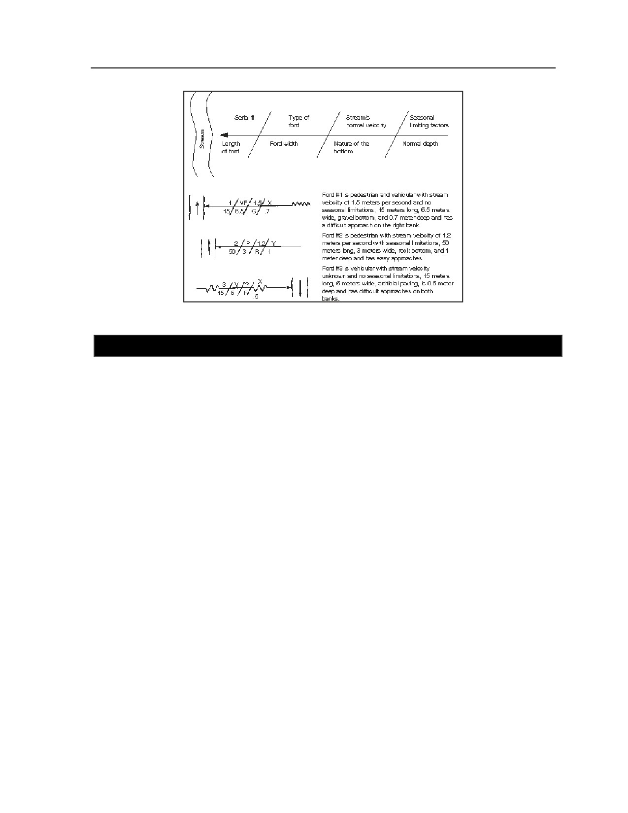
Appendix G
Figure G-24. Ford symbols
SECTION VIII - FERRY CLASSIFICATION
G-62. Ferries are considered obstructions to traffic flow and are indicated by the abbreviation “OB” in the
route classification formula. Ferryboat construction varies widely and ranges from expedient rafts to ocean-
going vessels. Ferries differ in physical appearance and capacity depending upon the waterway’s width,
depth, and current and the characteristics of the traffic to be moved. Ferries may be propelled by oars;
cable and pulleys; poles; the stream current; or steam, gasoline, or diesel engines.
CIVIL FERRIES AND FERRY SITES
G-63. The capacity of a civil ferryboat is normally expressed in tons and its capacity (total number of
passengers and/or vehicles, as well as cargo). In addition, it is often assigned an MLC number. Because
ferries vary in capacity, be sure to record the capacity of each ferry when more than one is used at a given
site.
G-64. Ferry slips (or piers) are usually provided on each shore to permit easy loading of passengers, cargo,
and vehicles. The slips may range from simple log piers to elaborate terminal buildings. A distinguishing
characteristic of a ferry slip is often the floating pier that adjusts, with changes in the water depth, to the
height of the ferryboat.
G-65. Approach routes to ferry installations have an important bearing on use of the ferry. Reconnoitering
and recording the conditions of the approaches (including the load-carrying capacity of landing facilities) is
very important.
G-66. Limiting characteristics of ferry sites that should be considered include the following:
z
Width of the water barrier from bank to bank.
z
Distance and time required for the ferryboat to travel from one bank to the other.
z
Depth of the water at each ferry slip.
z
Factors influencing the possible defense of each landing site.
G-67. Climatic conditions affect ferry operations. The platoon must consider data on tide fluctuations,
freezing periods, floods, excessive dry spells, and their effects on ferry operations. For example, fog and
ice substantially reduce the total traffic-moving capacity of the water route and increase the danger
associated with movement across the water.
G-28
FM 3-20.98
3 August 2009
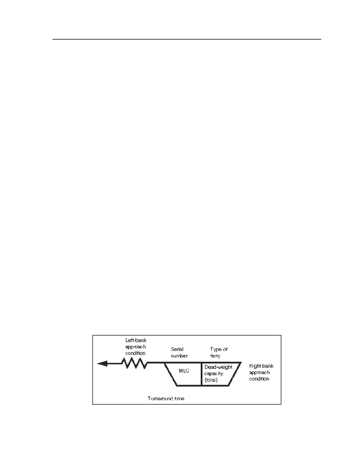
Essential Field Data
MILITARY FERRIES AND RAFTING
G-68. Reconnaissance personnel will be required to locate and report suitable sites for military rafting or
ferrying operations. Military floating bridges are currently available for such operations. Desirable site
characteristics include the following:
z
Current velocity between 0 and 1.6 meters per second.
z
Banks that permit loading without a great deal of preparation.
z
Approaches that permit easy access and egress.
z
Strong, natural holdfasts.
z
Sites with no shoals, sandbars, or snags.
z
Sites clear of obstacles immediately downstream.
z
Sites clear of mines and booby traps.
z
Sites with sufficient depth to prevent grounding of the raft or ferry during loading, unloading, or
crossing operations.
z
Suitable raft-construction sites (dependent on type of raft).
z
Holding areas for vehicles awaiting passage.
z
A suitable road network to support crossing traffic.
FERRY INFORMATION
G-69. Record limited ferry information on maps or overlays by using the symbol shown in Figure G-25.
Refer to Figure G-26 for examples of completed ferry symbols. Ferry information includes the following:
z
Use an arrow to connect the ferry symbol to the geographic location of the ferry on a map or
overlay. The symbol may be drawn on the map or overlay on either side of the stream.
z
Assign a serial number to each ferry, using unit SOP, for later reference. Numbers must not be
duplicated within any one map sheet, overlay, or document. Some maps will already show a
ferry serial number; if so, use this number for the reconnaissance.
z
Identify the type of ferry, listing “V” for vehicular or “P” for pedestrian after the serial number.
If the ferry can haul vehicles, it can also haul pedestrians.
z
List the deck’s MLC in the bottom left box of the symbol. Most ferries have this information on
their data plate.
z
List the dead-weight capacity of the ferry. This is the MLC plus the actual weight of the ferry, in
short tons.
z
Show turnaround time, in minutes, required to cross the waterway, unload, and return.
G-70. When drawing the approach condition portion of the symbol, pay attention to the direction of stream
flow. Left and right banks are determined by looking downstream. Approach conditions are determined in
the same manner as for fords. Use irregular lines on the corresponding side of the basic symbol to show a
difficult approach.
Figure G-25. Basic ferry symbol
3 August 2009
FM 3-20.98
G-29
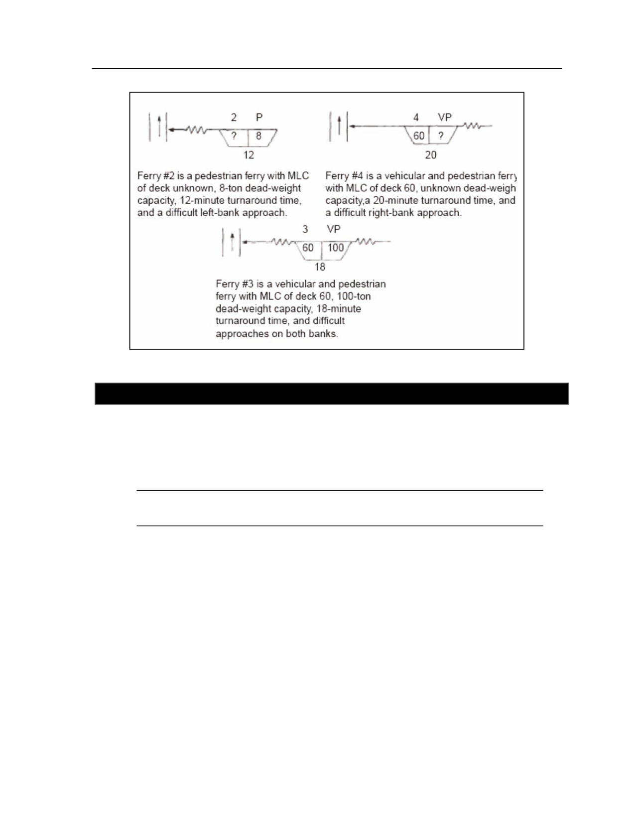
Appendix G
Figure G-26. Sample ferry symbols
SECTION IX - BRIDGE CLASSIFICATION
G-71. The reconnaissance or platoon conducts a bridge reconnaissance to ensure that they know the load-
carrying capabilities of each bridge along a specific route. In some situations, this also identifies which
bridges are unusable and provides a rough estimate of the materials needed to destroy the bridge. When
tactical situation allows, platoon leaders should request engineer support to determine the most accurate
capabilities or damages to a bridge. Platoons may employ UAS overflights for preview of the bridge prior
to reaching their locations.
Note. Platoons may deploy into regions where bridge classifications for most roads and routes
is already calculated and posted for civilian traffic.)
G-72. This section reviews the basics of hasty bridge load classification procedures and reconnaissance
procedures for bridge destruction. It will help vehicle operators to avoid loss of life or equipment due to
bridge failure by outlining procedures for determining what vehicles can cross a bridge. Vehicle operators
may cross without restrictions if their vehicle’s load class (including the load) is less than or equal to the
bridge’s load class. The vehicle’s load class can be found in the appropriate vehicle TM.
G-73. Common types of bridges that the platoon may encounter include the following (see Figure G-27 for
an illustration of bridges, by span type):
z
Timber or steel trestle bridge with timber deck.
z
Steel stringer bridge with concrete deck.
z
Concrete-steel stringer bridge.
z
Concrete T-beam.
z
Bridge with asphalt surface.
z
Masonry arch bridge.
G-30
FM 3-20.98
3 August 2009
Essential Field Data
REQUIRED INFORMATION
G-74. To classify a bridge, you must acquire the necessary information concerning the bridge’s basic
components, including the following:
z
Approaches (the portions of a route leading to a bridge). Approaches may be mined or booby-
trapped, requiring thorough investigation during a reconnaissance.
z
Substructure
(lower part of a bridge). The substructure consists of the abutments and
intermediate supports that transfer the bridge’s load to the ground. It is important to measure all
aspects of an abutment, including its height, width, and length; the abutment wings; and the
intermediate supports for bridge demolition missions. It may be more feasible to destroy the
intermediate supports or abutments when compared to the rest of the bridge structure.
z
Superstructure
(upper part of a bridge). The superstructure consists of the following
components (see Figure G-28):
Stringers. These rest on and span the distance between the intermediate supports or
abutments. Stringers are the superstructure’s main load-carrying members. They receive the
load from the flooring and the vehicles and transfer it to the substructure.
Flooring system. This often consists of both decking and tread. The decking is laid directly
over the stringers at right angles to the centerline of the bridge. The tread is laid parallel to
the centerline of the bridge and between the curbs.
Curbs. These are placed at both edges of the flooring to guide the vehicles. A vehicle with
an axle that is wider than the traveled-way width (between the curbs) cannot cross the
bridge. Most bridges, however, allow for vehicular overhang beyond the normal traveled
area. This allowance is called horizontal clearance above the curbs and is a safety factor.
Platoon leaders s must perform a risk analysis before attempting such a crossing.
Railings. These are located along the bridge to guide drivers and to protect vehicular and
foot traffic.
Trusses. These are used in some bridge superstructures, either above or below the traveled
way, to increase the load-carrying capacity. A truss is a structural element made of several
members joined together to form a series of triangles.
Number of members in each span. This is noted where applicable (for example, for
stringer bridges and concrete T-beam bridges). Exact dimensions of specific bridge
members are taken as outlined later in this section.
Span length. This is measured from center to center of the supports. The bridge’s
classification is usually based on the weakest span. If the weakest span is apparent, no
other spans need to be reconnoitered. If the weakest span is difficult or impossible to
locate, however, all spans must be classified. Even if several spans look identical, actual
measurements should be taken to prevent error.
Traveled-way width. This is measured between the inside faces of the curbs. On a truss
bridge, however, the horizontal clearance is measured from a point 1.21 meters (4 feet)
above the roadway.
Note. Figure G-27 illustrates various types of bridges, by span type, that the platoon may
encounter. Figure G-28 shows components of the bridge superstructure.
3 August 2009
FM 3-20.98
G-31
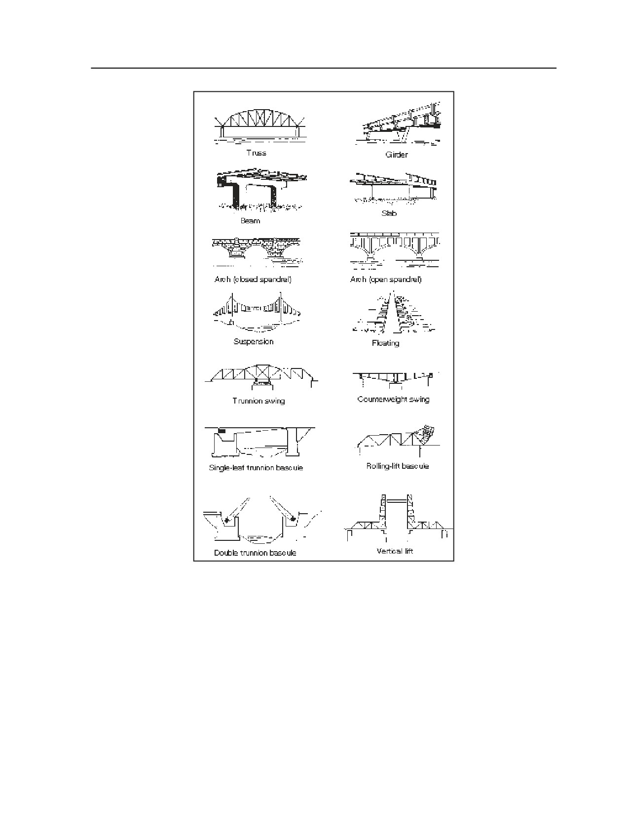
Appendix G
Figure G-27. Typical bridges (by type of span)
G-32
FM 3-20.98
3 August 2009
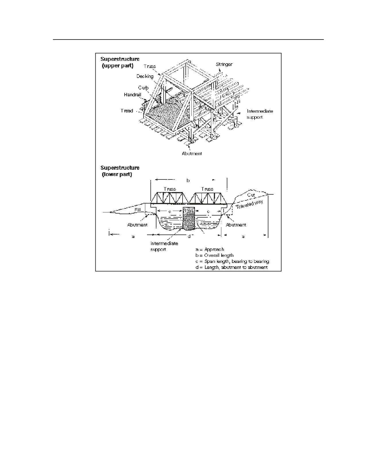
Essential Field Data
Figure G-28. Bridge components
HASTY BRIDGE CLASSIFICATION TECHNIQUES
G-75. In wartime, the platoon will sometimes have to cross underclass bridges. To determine whether the
bridge can be crossed safely, assess it using the following considerations:
z
Is there a data plate on the side of or underneath the bridge?
z
Can the unit’s largest vehicle cross with at least two of the bridge supports under it? (See Figure
G-29.)
z
If the bridge fails, will the vehicle fall a distance not exceeding its own length? The risk is
minimized if the drop is shallow enough that the vehicle can be easily retrieved and the crew can
avoid serious injury.
z
What does the bridge span? If it spans a railroad track or a highway, the risk of crossing is
probably too great. If the bridge crosses a stream, small ravine, or creek, however, it may be
worth the risk to attempt a crossing.
3 August 2009
FM 3-20.98
G-33
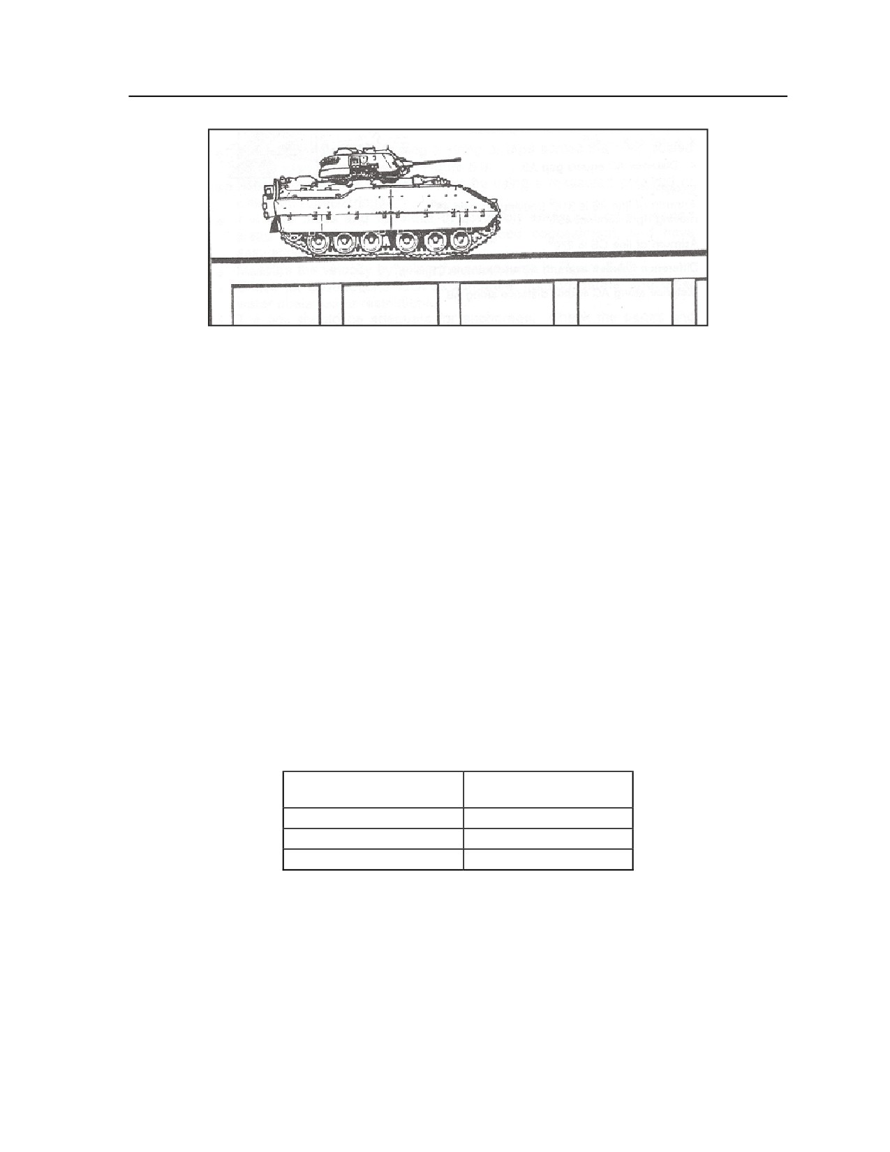
Appendix G
Figure G-29. BFV crossing a bridge with two supports under it
G-76. If the risk is acceptable, the senior member of the crossing element should observe the bridge while
the first vehicle crosses. If the first vehicle causes no visible damage to the bridge, subsequent vehicles
should cross one at a time, in the center of the bridge, at a constant speed, and without stopping or
accelerating. An observer should watch each vehicle from the side of the bridge to detect any sign of
bridge damage.
G-77. The following discussion focuses on hasty bridge classification techniques for MLC 30 and MLC 70
bridges.
CONCRETE SLAB MLC 30 BRIDGE
G-78. Before crossing a concrete slab MLC 30 bridge, use the following evaluation steps to determine if it
is safe to cross:
z
Step 1. Is the roadway width 4.5 meters (14.75 feet) or greater? Is there 4.3 meters (14 feet) of
overhead clearance? If the answer to both of these questions is yes, go to step 2; if the answer to
either question is no, do not cross.
z
Step 2. Measure the span length and deck thickness (as illustrated in Figure G-30). Compare
the span length and deck thickness to minimum standards using Table 3. Does the slab meet
minimum deck thickness for the corresponding span? If the answer is yes, it safe to cross MLC
30 traffic; if the answer is no, go to step 3.
Table G-3. Measurement correlations for a
concrete slab MLC 30 bridge
SPAN LENGTH
MINIMUM DECK
THICKNESS
30 feet
18 inches
20 feet
13 inches
10 feet
8 inches
z
Step 3. Take into account the following special condition: For each foot under the closest
higher span length shown, deck thickness can decrease by no more than ½ inch. Does the slab
meet minimum deck thickness required according to this special condition? If the answer is yes,
it is safe to cross MLC 30 traffic; if the answer is no, do not cross.
G-34
FM 3-20.98
3 August 2009
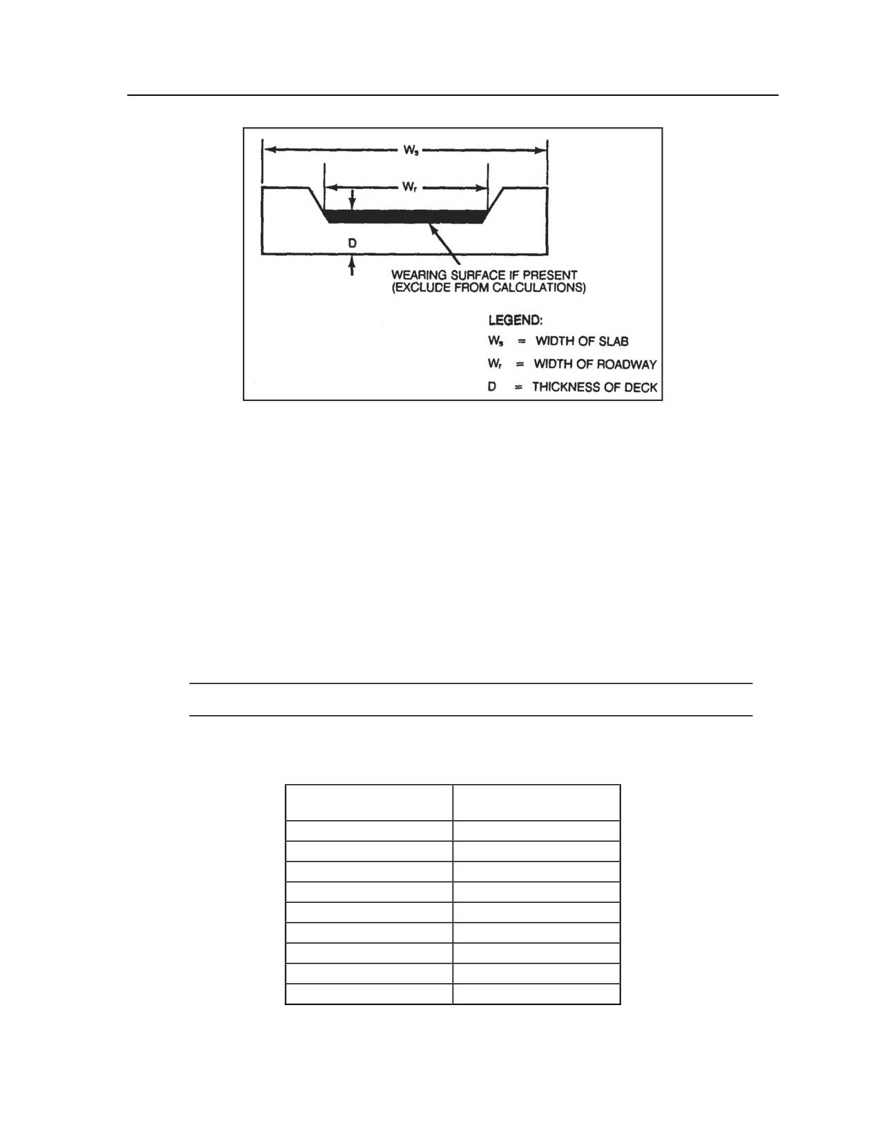
Essential Field Data
Figure G-30. Concrete slab MLC 30 bridge
CONCRETE T-BEAM MLC 30 BRIDGE
G-79. Before crossing a concrete T-beam MLC 30 bridge, use the following evaluation steps to determine
if it is safe to cross:
z
Step 1. Is the roadway width 4.5 meters (14.75 feet) or greater? Is there 4.3 meters (14 feet) of
overhead clearance? Is the deck at least 6 inches thick? If the answer to all three questions is
yes, go to step 2; if the answer to any question is no, do not cross.
z
Step 2. Measure the span length, stringer spacing, and depth of the stringer (as illustrated in
Figure G-31). Is the stringer spacing no less than 6 feet and no more than 8 feet? If the answer is
yes, go to step 3; if the answer is no, do not cross.
z
Step 3. Does the stringer depth meet the minimum dimension for the corresponding span length
shown in Table G-4? If the answer is yes, it is safe to cross MLC 30 traffic; if the answer is no,
do not cross.
Note. If the span length falls between designated lengths, use the next higher value.
Table G-4. Measurement correlations for a
concrete T-beam MLC 30 bridge
SPAN LENGTH
MINIMUM STRINGER
DEPTH
20 feet
15 inches
30 feet
20 inches
40 feet
25 inches
50 feet
30 inches
60 feet
35 inches
70 feet
40 inches
80 feet
44 inches
90 feet
50 inches
100 feet
57 inches
3 August 2009
FM 3-20.98
G-35
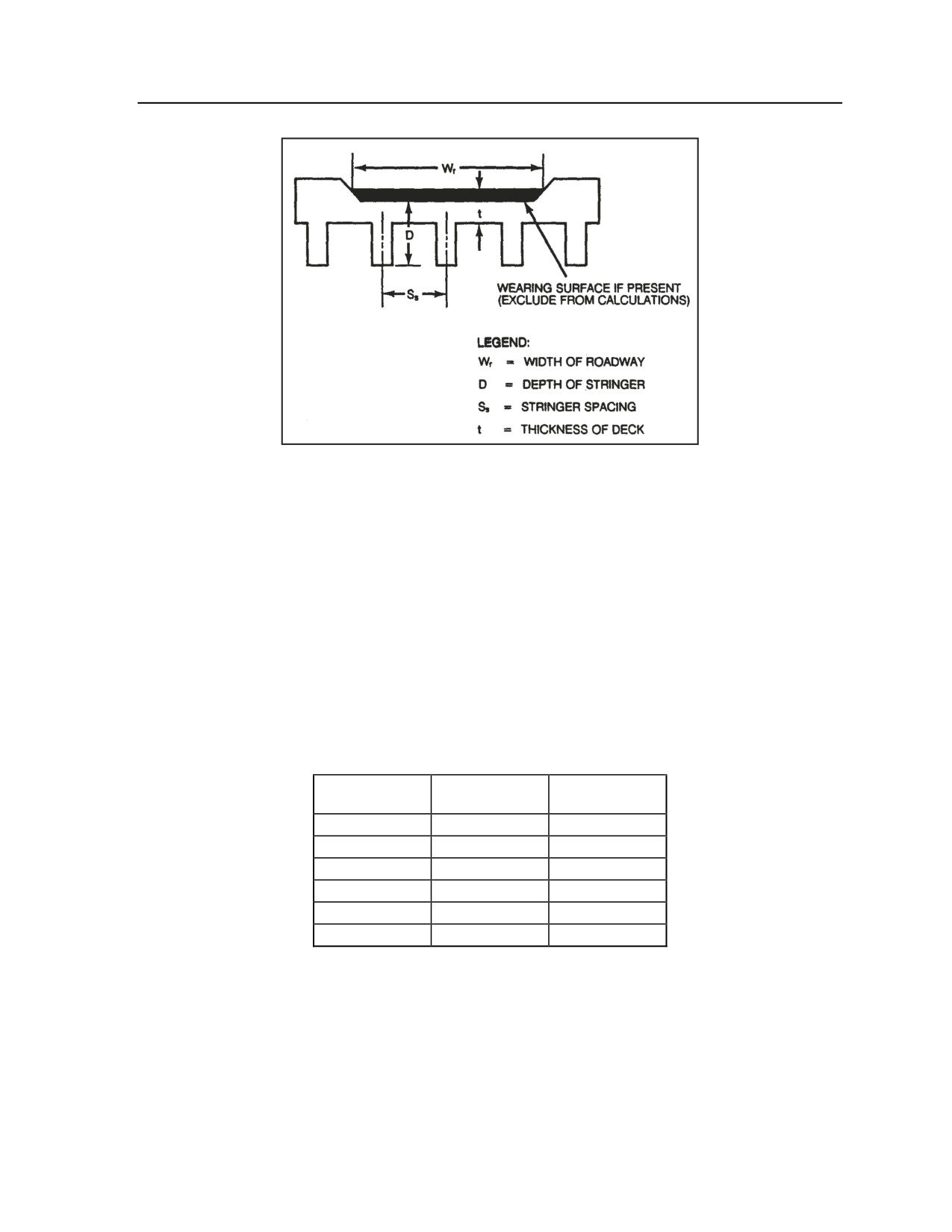
Appendix G
Figure G-31. Concrete T-beam MLC 30 bridge
MASONRY ARCH MLC 30 BRIDGE
G-80. Before crossing a masonry arch MLC 30 bridge, use the following evaluation steps to determine if it
is safe to cross:
z
Step 1. Is the roadway width 4.5 meters (14.75 feet) or greater? Is there 4.3 meters (14 feet) of
overhead clearance? If the answer to both questions is yes, go to step 2; if the answer to either
question is no, do not cross.
z
Step 2. Measure the span length, arch ring, and fill (as shown in Figure G-32). Compare these
measurements to minimum standards using Table G-5. Do the arch ring and fill meet minimum
required dimensions for the designated span? If the answer is yes, it is safe to cross MLC 30
traffic; if the answer is no, go to step 3.
Table G-5. Measurement correlations for
a masonry arch MLC 30 bridge
SPAN LENGTH
MINIMUM
MINIMUM FILL
ARCH RING
10 feet
9 inches
None
15 feet
9 inches
6 inches
20 feet
9 inches
12 inches
30 feet
13.5 inches
18 inches
40 feet
18 inches
12 inches
50 feet
22.5 inches
12 inches
z
Step 3. Take into account the following special condition: Fill can be reduced if the thickness
of the arch ring exceeds the specifications above. Compare these measurements using Table G-
6. Does the bridge span meet the minimum fill requirements for the corresponding arch ring
thickness according to this special condition? If the answer is yes, it is safe to cross MLC 30
traffic; if the answer is no, do not cross.
G-36
FM 3-20.98
3 August 2009
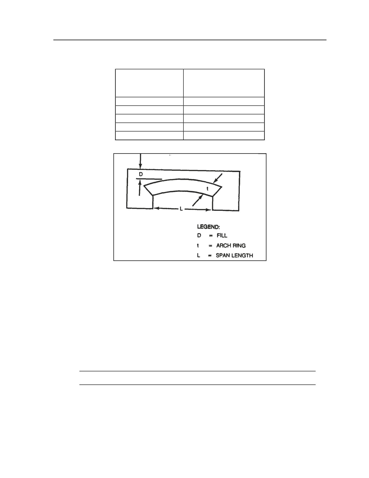
Essential Field Data
Table G-6. Special conditions for minimum fill
on a masonry arch MLC 30 bridge
SPAN LENGTH
FOR EACH 1-INCH
INCREASE ABOVE THE
MINIMUM ARCH RING, FILL
CAN DECREASE BY:
15 feet
3 inches
20 feet
2-2/3 inches
30 feet
2-2/3 inches
40 feet
1-1/3 inches
50 feet
2-2/3 inches
Figure G-32. Masonry arch MLC 30 bridge
STEEL STRINGER MLC 30 BRIDGE WITH CONCRETE DECK
G-81. Before crossing a steel stringer MLC 30 bridge with a concrete deck, use the following evaluation
steps to determine if it is safe to cross:
z
Step 1. Is the roadway width 4.5 meters (14.75 feet) or greater? Is there 4.3 meters (14 feet) of
overhead clearance? Is the deck at least 5 inches and no more than 8 inches thick? If the answer
to all three questions is yes, go to step 2; if the answer to any question is no, do not cross.
z
Step 2. Measure the span length, stringer spacing, and stringer height and width (as illustrated
in Figure G-33). Using Table G-7, find the row and column corresponding to the bridge’s span
length and stringer spacing. Does the stringer meet the minimum requirements for overall height
and width? If the answer is yes, it is safe to cross MLC 30 traffic; if the answer is no, do not
cross.
Note. If these measurements fall between the values given, use the next higher measurement.
3 August 2009
FM 3-20.98
G-37