FM 3-34.214 (FM 5-250) EXPLOSIVES AND DEMOLITIONS (July 2007) - page 2

Chapter 2
Table 2-3. M21 Characteristics
Tabulated Data
Length
2.25 to 2.35 in
Aluminum-tube detonator
Diameter
0.230 to 0.241 in
Material
Various plastics
Shock tube
Length
500 ft
Diameter
0.09 in
Detonator
Lead azide, PETN
Filler
Shock tube
HMX and aluminum
Actuation method
Impulse from attached minitube
Shipping and Storage Data
DOD hazard class
1.4S
QD/DIV/SCG
DOT hazard class
1.4S
DOT label
Explosive
1.4S
Proper shipping name
Detonating, assemblies, nonelectric
UN serial number
0500
NSN
1375-01-494-6945
DODAC
Live: MN88
Inert: MN89
DOT container marking
NEW (per cap)
19 gr
Drawing
12999559
Specification
QAA-1430
8 units per fiberboard box; 5 boxes per wooden
Packaging
box (40)
Dimensions
44 by 16.38 by 17.38 in
Cube
5.25 cu ft
Packing box
NEW
0.28 lb
Gross weight of package
20 lb
References
TM 9-1375-213-34&P
TM 9-1375-213-12
DOD Consolidated Ammunition Supply Catalog
M13 NONELECTRIC BLASTING CAP WITH A 1,000-FOOT SHOCK
TUBE
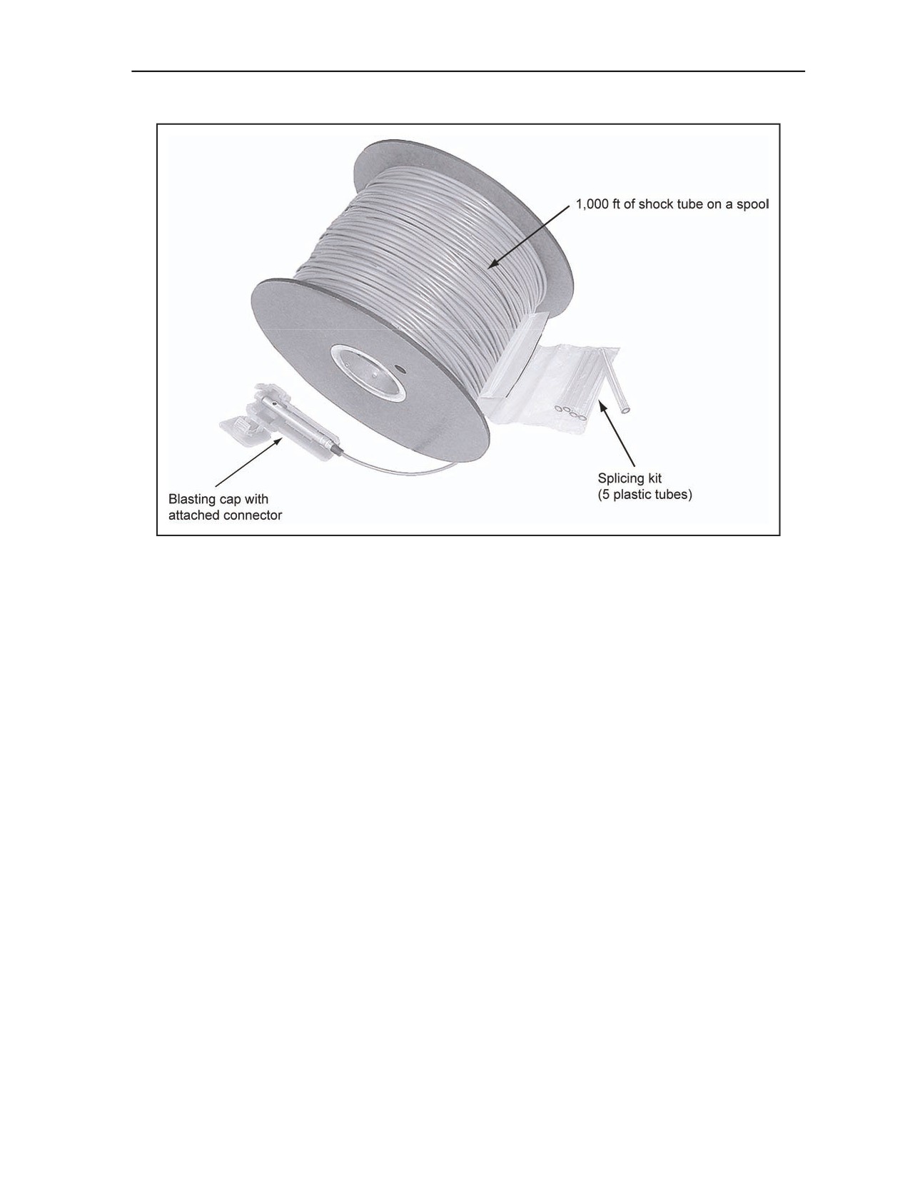
2-78. The M13 is a low-strength blasting cap, factory-crimped to a 1,000-foot length of shock tube. A
special plastic connector is attached to the detonator to facilitate quick and easy attachment to the shock
tube of up to five shock tubes or five low-strength detonating cords or one strand of standard detonating
cord. The M13 is provided on a spool as shown in Figure 2-39.
2-40
FM 3-34.214
11 July 2007
Initiating Sets, Priming Methods, Firing Systems, and Modernized Demolition Initiators
Figure 2-39. M13 Shock Tube Component and Blasting Cap With a Splicing Kit
USE
2-79. The M13 is used as a transmission line in a firing system. It does not have enough output to initiate
military explosives reliably.
FUNCTIONS
2-80. The M13 functions by sending an initiating shock or a small detonation through the shock tube to the
blasting cap. This blasting cap then actuates five shock tubes, five low-strength detonating cords, or one
strand of high-strength detonating cord held by the plastic connector. The M13’s shock tube must be
initiated by another blasting cap or by the M81 fuse igniter. Table 2-4, page 2-42, shows the M13
characteristics.
11 July 2007
FM 3-34.214
2-41

Chapter 2
Table 2-4. M13 Characteristics
Tabulated Data
Length
2.7 in
Aluminum-tube detonator
Diameter
0.296 in
Material
Various plastics
Shock tube
Length
1,000 ft
Diameter
0.118 in
Detonator
Lead azide, PETN
Shock tube
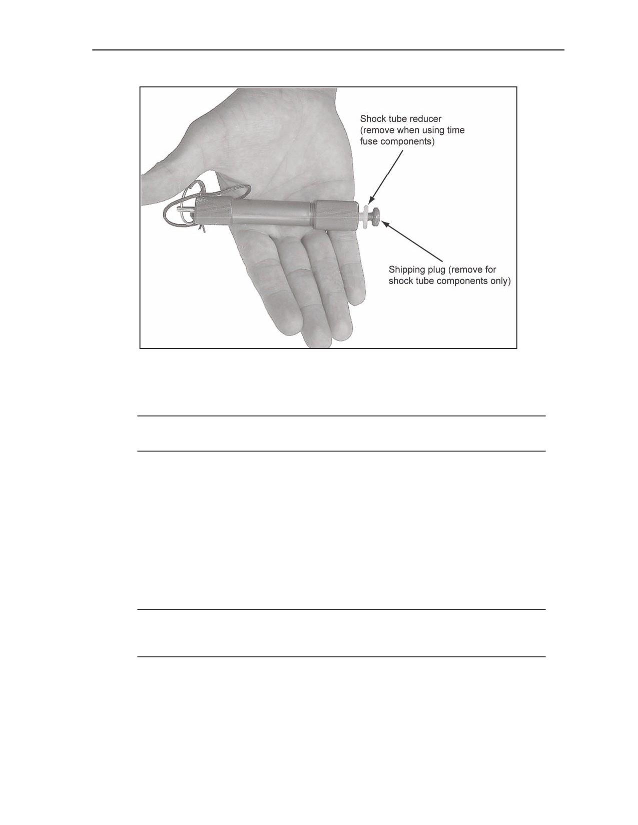
HMX and aluminum
Filler
Shock from the detonation of a blasting cap or
Actuation method
the primer of the M81 igniter
Shipping and Storage Data
DOD hazard class
1.4S
QD/DIV/SCG
DOT hazard class
1.4S
DOT label
Explosive
1.4S
Proper shipping name
Detonator assemblies, nonelectric
UN serial number
0500
NSN
1375-01-415-1231
DODAC
Live: MN03
Inert: none
NEW (per cap)
13 gr
DOT container marking
Drawing
12972629
Specification
QQA-1459
Pre-1999: 4 units per cardboard box; 6 boxes per
wooden box (24)
Packaging
Post-1999: 4 units per fiberboard box; 5 boxes
per wooden box (20); 4 wooden boxes per pallet
(80)
Pre-1999 production: 46 by 21 by 21 in
Dimensions
Post-1999 production: 48.75 by 19.8 by 20.75 in
Pre-1999 production: 11.74 cu ft
Cube
Post-1999 production: 11.41 cu ft
Packing box
Pre-1999 production: 0.298 lb
NEW
Post-1999 production: 0.2486 lb
Gross weight of
Pre-1999 production: 169 lb
package
Post-1999 production: 176 lb
References
TM 9-1375-213-34&P
DOD Consolidated Ammunition Supply Catalog
2-42
FM 3-34.214
11 July 2007
Initiating Sets, Priming Methods, Firing Systems, and Modernized Demolition Initiators
M23 NONELECTRIC BLASTING CAP WITH A 1,000-FOOT
MINISHOCK TUBE
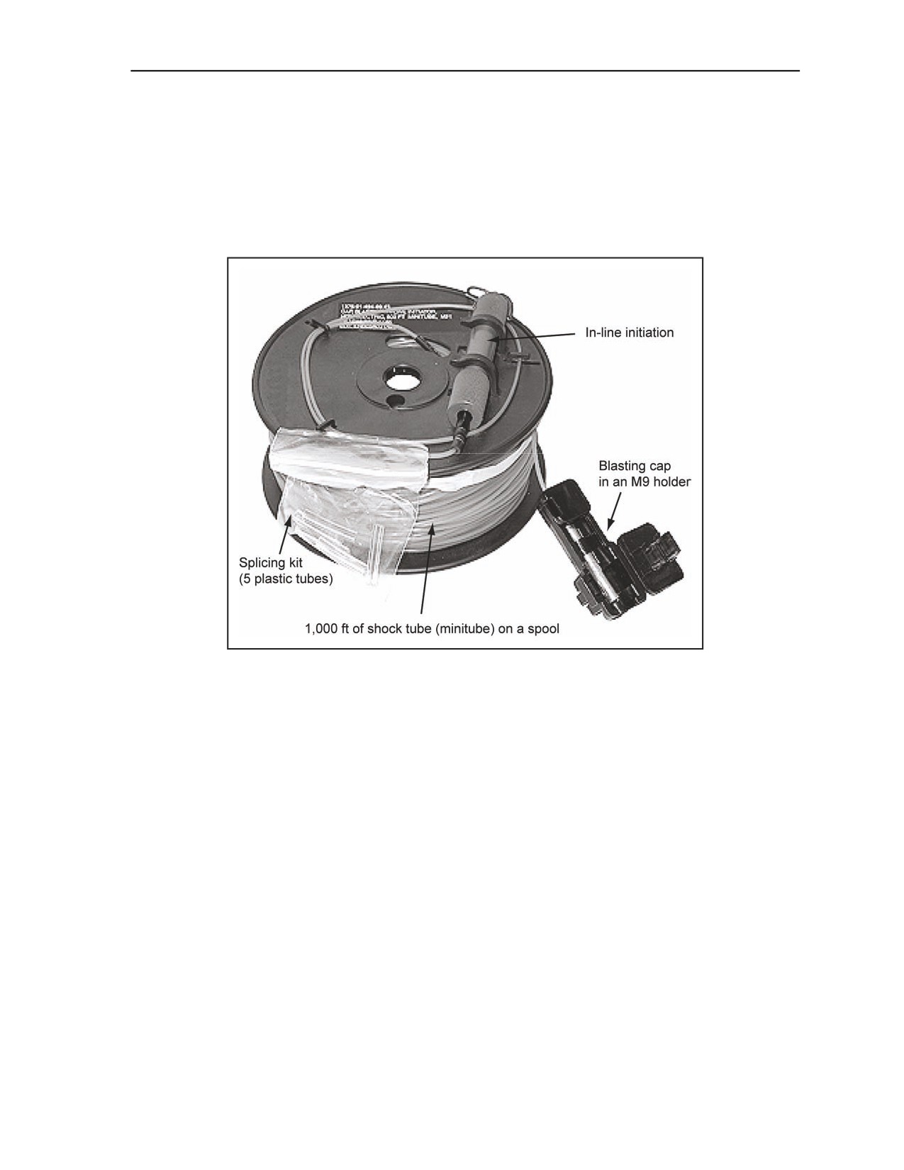
2-81. The M23 consists of a high-strength blasting cap precrimped to a 1,000-foot length of minitube. The
M23 is about one-third the size and weight of the M13. The M23 has a modified M81E1 igniter moisture
cap with a protected ignition primer factory-crimped that is installed to an in-line initiator on the minitube.
The M23 has a M9 holder already connected to the high-strength cap (Figure 2-40).
Figure 2-40. M23 MDI 1,000-Foot Shock Tube Component
USE
2-82. The M23 is used to transmit a shock tube detonation impulse from an initiator (or another relay cap).
Unlike the M13, a high-strength blasting cap or booster will not have to be added as part of the
transmission line. The M23 high-strength cap can be secured into an M9 holder to provide the capability to
initiate up to five additional shock tubes or five low-strength detonating cords or one strand of detonating
cord. The M23 high-strength cap can also be used to prime military explosives.
FUNCTIONS
2-83. The M23 functions by sending an initiating shock or small detonation through the shock tube to the
blasting cap. This blasting cap then actuates five shock tubes, five low-strength detonating cords, or one
strand of high-strength detonating cord held by the plastic connector. The M23’s shock tube must be
initiated by another blasting cap or by the M81E1 in-line initiators. Table 2-5, page 2-44, shows the M23
characteristics.
11 July 2007
FM 3-34.214
2-43

Chapter 2
Table 2-5. M23 Characteristics
Tabulated Data
Aluminum-tube
Length
2.25 to 2.35 in
detonator
Diameter
0.230 to 0.241 in
Material
Various plastics
Shock tube
Length
1,000 ft
Diameter
0.09 in
Detonator
Lead azide, PETN
Filler
Shock tube
HMX and aluminum
Actuation method
Impulse from attached minitube
Shipping and Storage Data
DOD hazard class
1.4S
QD/DIV/SCG
DOT hazard class
1.4S
DOT label
Explosive
1.4S
Proper shipping name
Detonating, assemblies, nonelectric
UN serial number
0500
NSN
1375-01-494-6941
DODAC
Live: MN90
Inert: none
DOT container marking
NEW (per cap)
19 gr
Drawing
12999561
Specification
QAA-1430
4 units per fiberboard box; 5 boxes per wooden
Packaging
box (20); 4 wooden boxes per pallet (80)
Dimensions
44 by 16.38 by 17.38 in
Cube
5.25 cu ft
Packing box
NEW
0.22 lb
Gross weight of package
17 lb
References
TM 9-1375-213-12
TM 9-1375-213-34&P
DOD Consolidated Ammunition Supply Catalog
M14 NONELECTRIC BLASTING CAP WITH A DELAY
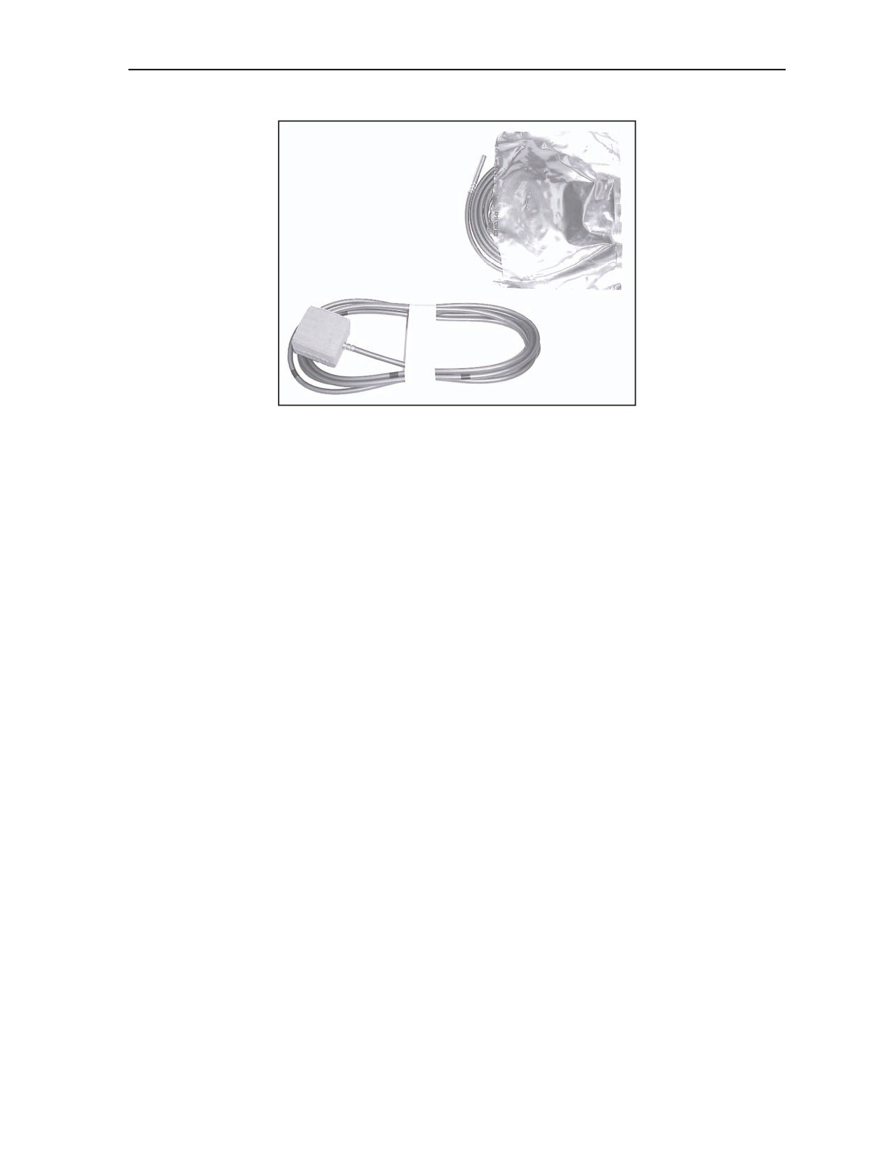
2-84. The M14 is a high-strength blasting cap, factory-crimped to about 7 ½-foot length of time fuse. The
M14 is marked with yellow or black bands that represent a nominal 1 minute of burn time instead of having
a yellow band every 18 inches as on the M700 time fuse. The free end of the fuse is moisture-sealed and
must be cut off to the selected time band when being prepared for ignition (Figure 2-41).
2-44
FM 3-34.214
11 July 2007
Initiating Sets, Priming Methods, Firing Systems, and Modernized Demolition Initiators
Figure 2-41. M14 Time Fuse Component (Various Vendors)
USE
2-85. The M14 is used to detonate military explosives and initiate shock tube, low-strength detonating
cord, and detonating cord after being ignited. In dual initiation, an M14 can be connected to a line main or
transmission line and be used as the primary or secondary initiation system.
FUNCTIONS
2-86. The M14 functions by sending an initiating flame (from a time-blasting fuse igniter or a match)
slowly through the length of the time-blasting fuse to the blasting cap. The 1-minute bands on the time fuse
have been factory-calibrated. The burn time will increase with altitude and colder temperatures. The M14
has been designed to allow a nominal 5-minute delay, under all weather and altitude conditions, to allow
personnel to move to the minimum safe distance (MSD) from the explosive charges being detonated. If
greater time accuracy is required under specific altitude and weather conditions, an M14 from the same lot
should be tested. The M14 being tested should be timed to the detonation of the cap to provide an actual
burn time. This will allow the operator to adjust the time for the detonation of the explosive system or main
charge. Table 2-6, page 2-46, shows the M14 characteristics.
11 July 2007
FM 3-34.214
2-45

Chapter 2
Table 2-6. M14 Characteristics
Tabulated Data
Length
2.25 to 2.35 in
Aluminum-tube detonator
Diameter
0.230 to 0.241 in
Material
Plastic-covered fiber
Time-blasting fuse
Length
About 7.5 ft
Diameter
0.25 in
Detonator
Lead styphnate, lead azide, PETN
Filler
Time fuse
Black powder
Actuation method
M81 fuse igniter or flame from a match
Shipping and Storage Data
DOD hazard class
1.4S
QD/DIV/SCG
DOT hazard class
1.4S
DOT label
Explosive
1.4S
Proper shipping name
Detonators, nonelectric
Pre-1999: 0455
UN serial number
Post-1999: 0500
Pre-1999 production: 1375-01-415-1233
NSN
Post-1999 production: 1375-01-482-7380
DODAC
Live: MN06
Inert: MN37
DOT container marking
Pre-1999 production: 16 gr
NEW (per cap)
Post-1999 production: 16 gr
Drawing
12982929
Specification
QAA-1424B
Pre-1999 production: 10 units per fiberboard
box; 6 boxes per wooden box (60)
Packaging
Post-1999 production: 10 units per fiberboard
box; 4 boxes per wooden box (40)
Dimensions
26 by 18 by 11 in
Cube
2.8 cu ft
Packing box
Pre-1999 production: 1.554 lb
NEW
Post-1999 production: 1.6 lb
Pre-1999 production: 57 lb
Gross weight of package
Post-1999 production: 86 lb
References
TM 9-1375-213-34&P
DOD Consolidated Ammunition Supply Catalog
M18 NONELECTRIC BLASTING CAP WITH A DELAY
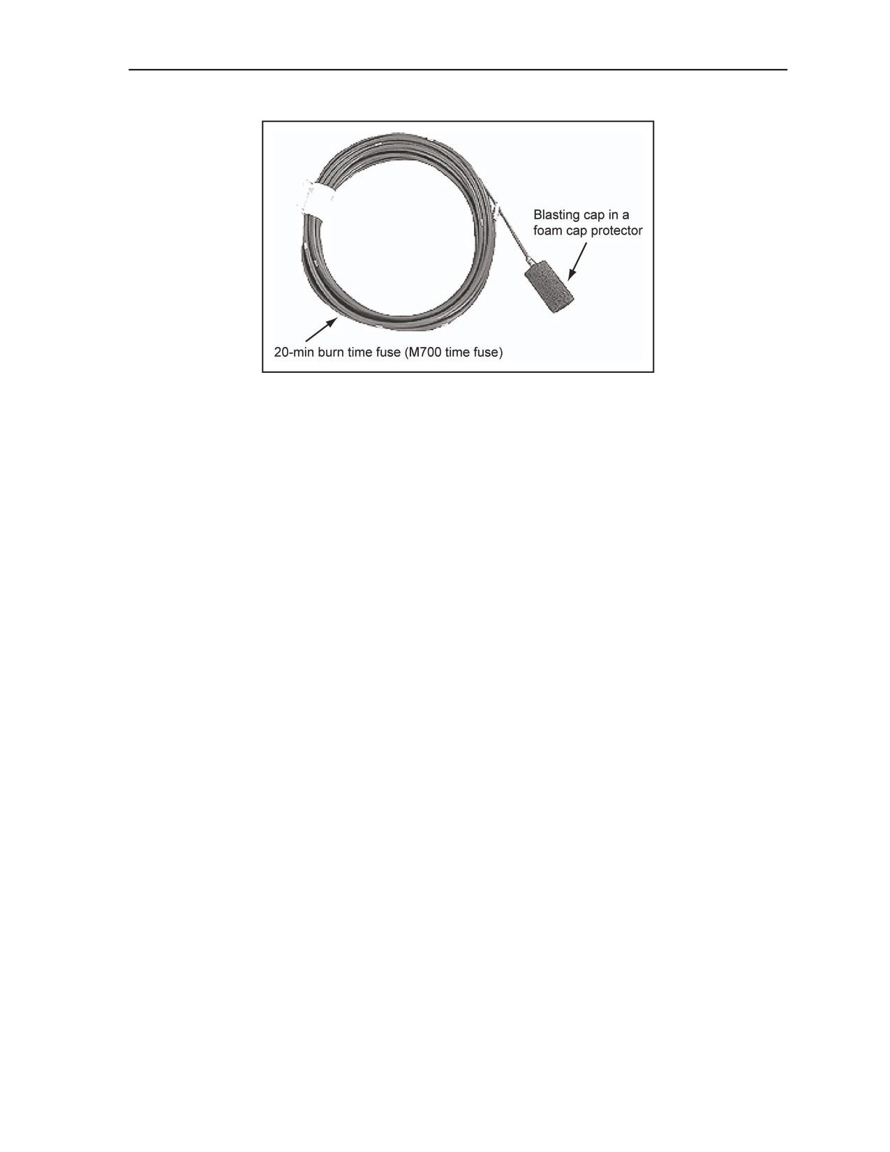
2-87. The M18 is a high-strength blasting cap, factory-crimped to about 30-foot length of time-blasting
fuse. The black bands represent 1 minute of burn time. The free end of the fuse is moisture-sealed and must
be cut off to the selected time band when being prepared for ignition (Figure 2-42).
2-46
FM 3-34.214
11 July 2007
Initiating Sets, Priming Methods, Firing Systems, and Modernized Demolition Initiators
Figure 2-42. 20-Minute Burn Time M18 Component
USE
2-88. The M18 is used to detonate all standard military explosives. It is also used to initiate shock tube
blasting caps and detonating cord up to 20 minutes after being ignited.
FUNCTIONS
2-89. The M18 functions by sending an initiating flame (from a fuse igniter or a match) slowly through the
length of the time-blasting fuse to the factory-crimped blasting cap. The 1-minute bands on the time fuse
have been calibrated at sea level at a temperature of 125°F. The burn time will increase with altitude and
colder temperatures. The M18 has been designed to allow a nominal 20-minute delay under all weather and
altitude conditions. This allows personnel to move to the MSD from the emplaced explosive charges being
detonated. Table 2-7, page 2-48, shows the M18 characteristics.
11 July 2007
FM 3-34.214
2-47

Chapter 2
Table 2-7. M18 Characteristics
Tabulated Data
Aluminum-tube
Length
2.25 to 2.35 in
detonator
Diameter
0.230 to 0.241 in
Material
Plastic-covered fiber
Time-blasting fuse
Length
30-ft approximate length
Diameter
0.25 in
Detonator
Lead styphnate, lead azide, PETN
Filler
Time fuse
Black powder
Actuation method
M81 fuse igniter or flame from a match
Shipping and Storage Data
DOD hazard class
1.4S
QD/DIV/SCG
DOT hazard class
1.4S
DOT label
Explosive
1.4S
Proper shipping name
Detonators, nonelectric for blasting
UN serial number
0345
NSN
1375-01-449-9602
DODAC
Live: MN41
Inert: none
DOT container marking
NEW (per cap)
16 gr
Drawing
12982929
Specification
QAA-1424B
2 per barrier bag; 5 barrier bags inside box;
Packaging
4 boxes in overpack (40)
Dimensions
26 by 18 by 11 in
Cube
2.8 cu ft
Packing box
NEW
0.104 lb (for 60 caps NEW = 1.57 lb)
Gross weight of package
57 lb
References
TM 9-1375-213-34&P
DOD Consolidated Ammunition Supply Catalog
M15 NONELECTRIC BLASTING CAP WITH A DELAY
2-90. The M15 consists of two blasting caps, factory-crimped at each end of a 70-foot length of shock
tube. The blasting caps are slightly different in size and contain different delay elements. The shorter, low-
strength blasting cap is designed to initiate another piece of shock tube in the firing system, while the
longer high-strength blasting cap is designed to prime explosives. Since the M15 high-strength blasting cap
is commercially used in boreholes, two brightly colored plastic flags are attached to the shock tube near the
detonator. A red flag is attached 1 meter from the longer high-strength blasting cap, and a yellow flag is
attached 2 meters from the low-strength blasting cap (Figure 2-43).
2-48
FM 3-34.214
11 July 2007

Initiating Sets, Priming Methods, Firing Systems, and Modernized Demolition Initiators
Figure 2-43. M15 Delay Blasting Cap
DANGER
The M15 can only be used belowground in quarry operations
according to FM 3-34.465. Failure to comply may cause death or
permanent injury.
USE
2-91. The M15 is used to provide a delay element in a combination firing system to obtain staged
detonations. Delayed and staged detonations are essential in quarrying operations but are also used in
relieved-face cratering.
FUNCTIONS
2-92. The M15 sends an initiating shock (or small detonation) through the shock tube to both of the
blasting caps. These contain pyrotechnic-delay elements. The delay times in the two detonators are
different; one is 25 milliseconds (low-strength, smaller cap with a shock tube connector), and the other is
200 milliseconds (higher-strength, larger cap with a shock tube connector). The high-strength blasting cap
is slightly larger in diameter than a standard blasting cap and will not fit in a standard cap well. The M15
shock tube must be initiated by another MDI component. Table 2-8, page
2-50, shows the M15
characteristics.
11 July 2007
FM 3-34.214
2-49

Chapter 2
Table 2-8. M15 Characteristics
Tabulated Data
Length (low strength)
2.5 in
Length (high strength)
3.5 in
Diameter (low strength)
0.296 in
Aluminum-tube detonator
Diameter (high strength)
0.296 in
Low strength: 3 gr
NEW (per cap)
High strength: 15 gr
Material
Various plastics
Shock tube
Length
70 ft
Diameter
0.118 in
Detonator
Lead azide, PETN
Shock tube
HMX and aluminum
Filler
Shock from the detonation of a blasting cap or
Actuation method
detonating cord
Shipping and Storage Data
DOD hazard class
1.4S
QD/DIV/SCG
DOT hazard class
1.4S
DOT label
Explosive
1.4S
Proper shipping name
Detonator assemblies, nonelectric
UN serial number
0500
NSN
1375-01-447-2049
DODAC
Live: MN07
Inert: MN38
DOT container marking
NEW (per cap)
1.36 gr
Drawing
12972631
Specification
QAA-1425
Packaging
60 units per wood box; 4 boxes (240) per pallet
Dimensions
46 by 21 by 21 in
Cube
11.74 cu ft
Packing box
NEW
0.18 lb
Gross weight of package
118 lb
References
TM 9-1375-213-34&P
DOD Consolidated Ammunition Supply Catalog
M151 BOOSTER DEMOLITION CHARGE
2-93. The M151 is a nonelectric, insensitive initiation system that is factory-assembled by crimping a
secondary explosive booster onto a 10-foot length of low-strength detonating cord to allow the user to
2-50
FM 3-34.214
11 July 2007

Initiating Sets, Priming Methods, Firing Systems, and Modernized Demolition Initiators
preprime explosives for military operations and bury explosives primed with M151. The M151 has a
detonating cord clip like other MDI components for easy attachment to a line or ring main detonating cord.
A pentagonal-shaped tag affixed to the low-strength detonating cord identifies it as an M151 to preclude
incorrect connection within a firing system.
CAUTION
Do not use M151 low-strength detonating cord as a line or ring main.
The M151 is only used as a branchline and cannot be substituted for
standard detonating cord. Personal injury or damage to equipment
may result from long-term failure to follow correct procedures.
USE
2-94. The M151 is used to prime charges in situations where simultaneous initiation and detonation are
desired. Prepriming of charges allows a Soldier to transport the preprimed charge in the vehicle or on his
person. This also allows for the burial of an explosive charge.
WARNING
Never attach an M60 or M81 igniter to the M151. Failure to comply
could result in immediate personal injury or damage to
equipment.
FUNCTIONS
2-95. The M151 functions upon receiving an initiating shock from a blasting cap or other booster. When
the booster functions, it detonates the primed explosive charge. The M151 booster can be secured in the
M9 holder by using the small flap. Table 2-9, page 2-52, shows the M151 characteristics.
11 July 2007
FM 3-34.214
2-51

Chapter 2
Table 2-9. M151 Characteristics
Tabulated Data
Material
PETN
Aluminum-tube booster
Length
2.25 to 2.35 in
cap
Diameter
0.230 to 0.241 in
Black fiber, with an environmental seal on one end,
Material
5 to 7.5 gr per ft
Green pentagonal-shaped identification tag on both
ends of the assembly, marked M151 to distinguish a
Marking
low-strength detonating cord from other MDI
Low-strength detonating
components
cord
Length
10 ft
Diameter
0.150 in
Shock from the detonation of a blasting cap or
Actuation method
detonating cord when an M151 is used as a
branchline
Shipping and Storage Data
DOD hazard class
1.4S
QD/DIV/SCG
DOT hazard class
1.4S
DOT label
Explosive
1.4S
Proper shipping name
Detonator, assemblies, nonelectric
UN serial number
0410
NSN
1375-01-467-8646
DODAC
Live: MN68
Inert: none
DOT container marking
NEW
87 gr
Drawing
D10451-1 Ensign-Bickford drawing
Specification
None
Packaging
20 per cardboard box; 6 boxes per overpack (120)
Dimensions
None
Cube
None
Packing box
NEW
1.13 lb
Gross weight of package
46 lb
References
TM 9-1375-213-34&P
DOD Consolidated Ammunition Supply Catalog
M152 BOOSTER DEMOLITION CHARGE
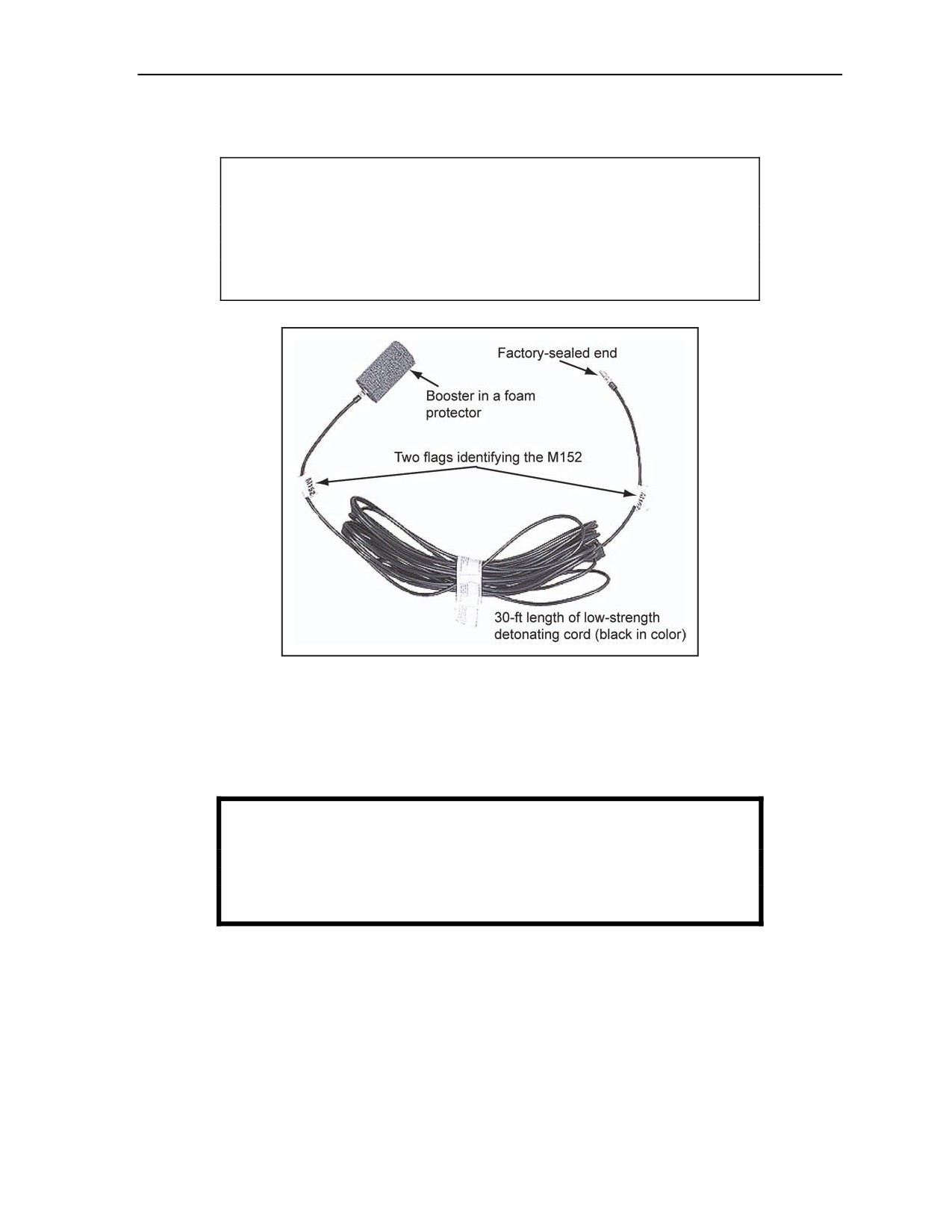
2-96. The M152 is a nonelectric insensitive initiation system that is factory-assembled by crimping a
secondary explosive booster onto a 30-foot length of low-strength detonating cord. This allows the user to
preprime explosives for military operations and bury explosives primed with M152. The M152 has a
detonating cord clip like other MDI components for easy attachment to a line or ring main detonating cord.
2-52
FM 3-34.214
11 July 2007
Initiating Sets, Priming Methods, Firing Systems, and Modernized Demolition Initiators
A pentagonal-shaped tag affixed to the low-strength detonating cord identifies it as an M152 to preclude
incorrect connection within a firing system (Figure 2-44).
CAUTION
Do not use M152 low-strength detonating cord as a line or ring main.
The M152 is only used as a branchline and cannot be substituted for
standard detonating cord. Personal injury or damage to equipment
may result from long-term failure to follow correct procedures.
Figure 2-44. M152 Low-Strength Detonating Cord Component
USE
2-97. The M152 is used to prime charges in situations where simultaneous initiation and detonation are
desired. Prepriming of charges allows a Soldier to transport the preprimed charge in the vehicle or on his
person. This also allows for the burial of an explosive charge.
WARNING
Never attach an M60 or M81 igniter to the M152. Failure to comply
could result in immediate personal injury or damage to
equipment.
FUNCTIONS
2-98. The M152 functions upon receiving an initiating shock from a blasting cap or other booster. When
the booster functions, it detonates the primed explosive charge. The M152 booster can be secured in the
M9 holder by using the small flap. Table 2-10, page 2-54, shows the M152characteristics.
11 July 2007
FM 3-34.214
2-53

Chapter 2
Table 2-10. M152 Characteristics
Tabulated Data
Material
PETN
Aluminum-tube booster
Length
2.25 to 2.35 in
cap
Diameter
0.230 to 0.241 in
Black fiber, with an environmental seal on one end,
Material
5 to 7.5 gr per ft
Green pentagonal-shaped identification tag on
Marking
both ends of the assembly, marked as M152
Low-strength detonating
Length
30 ft
cord
Diameter
0.150 in
Shock from the detonation of a blasting cap or
Actuation method
detonating cord when an M152 is used as a
branchline
Shipping and Storage Data
DOD hazard class
1.4S
QD/DIV/SCG
DOT hazard class
1.4S
DOT label
Explosive
1.4S
Proper shipping name
Detonator, assemblies, nonelectric
UN serial number
0410
NSN
Live: 1375-01-470-2399 Inert: 1375-01-467-8645
DODAC
Live: MN69
Inert: MN75
DOT container marking
NEW
197 gr
Drawing
D10451-2 Ensign-Bickford drawing
Specification
None
Packaging
20 per cardboard box; 3 boxes per overpack (60)
Dimensions
None
Cube
None
Packing box
NEW
1.44 lb
Gross weight of package
46 lb
References
TM 9-1375-213-34&P
DOD Consolidated Ammunition Supply Catalog
M19 NONELECTRIC BLASTING CAP WITH A DUAL MINISHOCK
TUBE
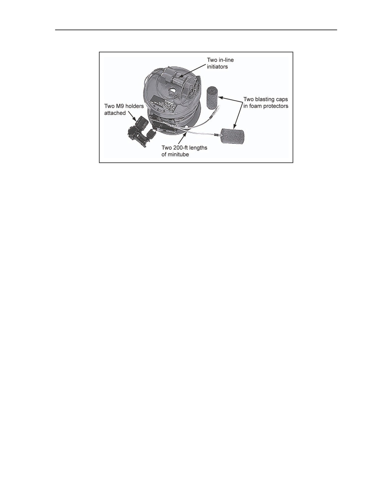
2-99. The M19 consists of a 200-foot length of dual minitube with an in-line initiator built into one end of
each of the two minitubes and a nonelectric, nondelay high-strength blasting cap attached to the other end
of each minitube. The minitube is smaller in diameter and possesses all the same characteristics of a shock
tube. The M81E1 igniter is attached to each in-line initiator. M9 plastic holders are provided in the
packaging for each M19 to facilitate quick and easy attachment to the minitube of additional blasting cap
components (Figure 2-45).
2-54
FM 3-34.214
11 July 2007
Initiating Sets, Priming Methods, Firing Systems, and Modernized Demolition Initiators
Figure 2-45. M19 Dual-Minitube and Blasting Cap Component
USE
2-100. The M19 is used to initiate standard military explosives and demolition charges by inserting the
blasting caps directly into an explosive or the cap well of demolition charges. The M19 is particularly
suited for urban terrain missions when very high reliability is required.
FUNCTIONS
2-101. The M19s minitube must be initiated by a blasting cap or by activating the firing assembly of the
M81E1 igniter. To actuate the M81E1, remove the cotter pin, and then pull the pull ring to the limit of its
travel. The pull ring rod then releases the firing pin. The firing assembly of the M81E1 igniter strikes the
M42C1 primer. The small detonation impulse (shock wave) from the primer is transmitted through the
minitube into a less sensitive explosive contained within its blasting cap. The blasting cap can actuate an
additional number of components held by the M9 plastic holder or can directly initiate explosive charges or
demolition devices. Table 2-11, page 2-56, shows the M19 characteristics.
11 July 2007
FM 3-34.214
2-55

Chapter 2
Table 2-11. M19 Characteristics
Tabulated Data
Aluminum-tube
Length
2.25 to 2.35 in
detonator
Diameter
0.230 to 0.241 in
Material
Various plastics
Shock tube
Length
200 ft (dual)
Diameter
0.09 in
Detonator
Lead azide, RDX
Filler
Shock tube
HMX and aluminum
Actuation method
Impulse from attached minitube
Shipping and Storage Data
DOD hazard class
1.4S
QD/DIV/SCG
DOT hazard class
1.4S
DOT label
Explosive
1.4S
Proper shipping name
Detonating assemblies, nonelectric
UN serial number
500
NSN
1375-01-494-6939
DODAC
Live: MN86
Inert: MN87
DOT container marking
NEW (per cap)
18 gr
Drawing
12999557
Specification
QAA-1431
Packaging
8 per fiberboard box; 5 boxes per wooden box (40)
Dimensions
44 by 16 by 21.5 in
Cube
8.76 cu ft
Packing box
NEW
0.31 lb
Gross weight of package
20 lb
References
TM 9-1375-213-12
TM 9-1375-213-34&P
DOD Consolidated Ammunition Supply Catalog
M9 BLASTING CAP AND SHOCK TUBE HOLDER
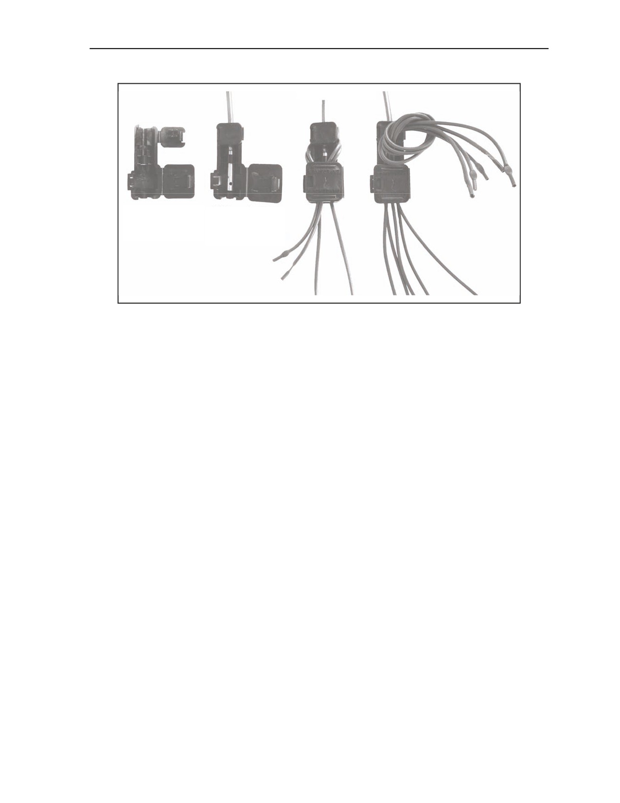
2-102. Plastic holders allow the connection of several shock tubes to high-strength blasting caps and
boosters (Figure 2-46). The M9 holder helps secure the connection of up to five shock tubes or low-
strength detonating cords to high-strength caps or boosters. The M9 holder can also be used to connect
high-strength blasting caps and boosters to detonating cord. When using the M9 holder, tape it closed.
Note. Do not connect the shock tube, low-strength detonating cord, or detonating cord in the
same holder. Detonating cord functions at a higher velocity than the HMX and aluminum in the
shock tube and may cause a break in the shock tube.
2-56
FM 3-34.214
11 July 2007
Initiating Sets, Priming Methods, Firing Systems, and Modernized Demolition Initiators
1 to 2 shock tubes
Overhand knot
M9 holder (both MDI cap/booster
flaps open)
secured in an M9
(small flap closed)
3 to 5 shock tubes
Figure 2-46. M9 Blasting Cap and Shock Tube Holder
USE
2-103. The M9 can accommodate and ensure proper proximity for initiating up to five shock tubes, five
low-strength detonating cords, or one strand of detonating cord from the blasting cap or booster. The M9
can also be used to connect the MDI blasting cap or booster to a detonating cord line or a ring main.
FUNCTIONS
2-104. Shock tubes must be positioned straight through the holder with an overhand knot when using one
or more (Figure 2-46). The blasting cap or booster is inserted and secured by closing the smaller hinged
flap. Insert the ends of the shock tubes through the channels in the holder. Close the large flap to secure the
overhand knot. Use tape to secure the large flap in place. See Table 2-12, page 2-58, for the M9
characteristics. In the event an M9 holder becomes unserviceable or is not available, use tape to make MDI
connections. To attach a blasting cap to MDI components using tape, ensure that all strands of shock tube
or low-strength detonating cord being connected are in contact with the blasting cap or booster and is
secured with tape.
11 July 2007
FM 3-34.214
2-57
Chapter 2
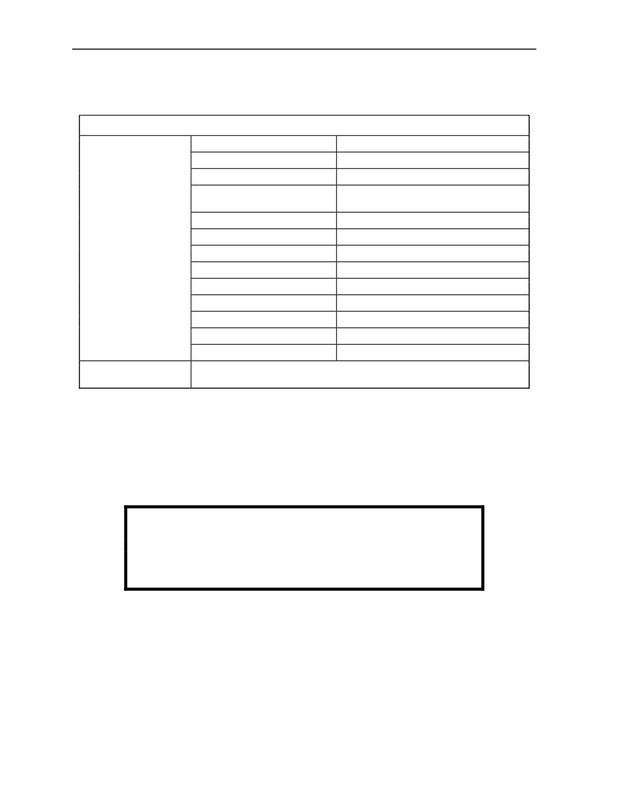
Table 2-12. M9 Characteristics
Tabulated data
Length
3.0 in
Diameter
1.3 in
Thickness
0.7 in
One cap or booster per five shock tubes on
Accommodation
low-strength detonating cords
Material
Polyethylene
Color
Black
Dimensions (closed)
NSN
1375-01-415-1229
DODAC
1375-ML45
Drawing
12972626
Specification
QAA-1423
Gross weight of item
1 oz
Packaging
500 units per box
Gross weight of package
49 lb
Because this item is designed for one-time use, continued use in training will
Limitations
wear out the hinges very quickly.
M81 TIME-BLASTING FUSE IGNITER WITH SHOCK TUBE
CAPABILITY
2-105. The M81 igniter will initiate the time fuse and shock tube end of MDI components(Figure 2-47).
The M81 is almost identical to the older M60 igniter, except the M81 has a screw-end cap with a green
shipping plug and a silicon shock tube reducer. The cap allows the M81 to accommodate the standard
shock tube or the standard-diameter, time-blasting fuse (M700). Extra care is required when connecting the
shock tube to an M81 igniter to ensure proper initiation of an explosive system.
WARNING
Never attach an M151, M152, or detonating cord to the M81
igniter. Failure to comply could result in immediate personal
injury or damage to equipment.
2-58
FM 3-34.214
11 July 2007
Initiating Sets, Priming Methods, Firing Systems, and Modernized Demolition Initiators
Figure 2-47. M81 Fuse Igniter
USE
2-106. The M81 igniter is used to ignite a time-blasting fuse or to initiate a shock tube.
Note. The standard M60 igniter (which has an almost identical appearance to the M81) will not
secure or reliably initiate the shock tube.
FUNCTIONS
2-107. The M81 is actuated as follows:
Loosen the screw cap and remove the shipping plug when using shock tube. Remove both the
shipping plug and shock tube reducer when using a time fuse (Figure 2-47).
Insert the freshly cut end of the time-blasting fuse or shock tube in the hole from which the plugs
were removed.
Tighten the screw cap to secure the fuse or shock tube.
Remove the safety (cotter) pin by squeezing the safety pin ends together then pulling on the
cord.
Pull the pull ring to the limit of its travel.
Note. When the M81 reaches its limit of travel, the pull ring rod releases the firing pin. The
spring forces the pin into the primer. The primer fires with a flame, and an explosive shock
ignites the fuse or initiates the shock tube.
2-108. Table 2-13, page 2-60, shows the M81characteristics.
11 July 2007
FM 3-34.214
2-59

Chapter 2
Table 2-13. M81 Characteristics
Tabulated Data
Length
4.0 in
Pull ring: 1.2 in
Body
Diameter
Body: 0.75 in
Material
Plastic
M42 primer
Primer mix
NEW (per igniter)
0.00005 lb (0.000023 gr)
Filler
Impact of the spring-loaded firing pin
Actuation method
on the primer is affected by the
operator pulling the pull ring.
Shipping and Storage Data
DOD hazard class
1.4S
QD/DIV/SCG
DOT hazard class
1.4S
DOT label
Explosive
1.4S
Proper shipping name
Lighters, fuse
UN serial number
0131
NSN
1375-01-415-1235
DODAC
Live: MN08
Inert: none
Drawing
12972638
DOT container marking
Specification
QAA-1442
Drawing
12972628
Specification
QAA-1423
Five igniters per paperboard box;
Packaging
one to a barrier bag; 6 bags (300
igniters) per wooden box
Dimensions
21.5 by 12 by 14.5 in
Cube
2.16 cu ft
Packing box
NEW
0.03 lb
Gross weight (with contents)
65 lb
References
TM 9-1375-213-34&P
DOD Consolidated Ammunition Supply Catalog
2-60
FM 3-34.214
11 July 2007

Initiating Sets, Priming Methods, Firing Systems, and Modernized Demolition Initiators
SECTION V - EXPLOSIVE CHARGES PRIMED WITH MODERNIZED
DEMOLITION INITIATORS
2-109. There are three methods of priming explosive charges—nonelectric (MDI), boosters (MDI), and
detonating cord. Only nonelectric (MDI) and boosters are discussed in this section. Priming charges with
MDI M151 or MDI M152 components or detonating cord are the preferred methods for reserve demolition
targets, which allow charges to be primed at state of readiness—state 1 (safe).
NONELECTRIC PRIMING
2-110. Use high-strength MDI blasting caps or boosters for priming explosive charges that are emplaced
aboveground. For priming explosive charges belowground, use the M151 or M152 booster. Use the M12
and M13 only as transmission lines in firing systems (refer to Section VI of this chapter).
WARNING
Do not insert blasting caps in explosive charges until ordered to
do so. Failure to comply could result in immediate personal injury
or damage to equipment.
2-111. MDI priming is safer and more reliable than the current nonelectric cap priming methods. MDI
blasting caps and boosters are already factory-crimped to precut lengths of shock tube or time-blasting fuse.
Because the caps are sealed units, they are resistant to moisture and will not misfire in damp conditions.
However, once the system has been spliced, reliability will be significantly degraded due to moisture. Also,
the human factor of incorrect crimping is removed, making MDI blasting caps and boosters extremely
reliable. MDI blasting caps and boosters can be used with priming adapters or can be inserted directly into
the explosive charge and secured with tape. If using priming adapters, place them on high-strength blasting
caps and boosters as outlined in the note below.
Note. Older MlA4 priming adapters must be slid down the full length of the shock tube or low-
strength detonating cord to the high-strength blasting cap or booster. To slide the priming
adapter on the free end of the shock tube, it will be necessary to cut off the end of the shock tube
to remove the sealed end cap, and then slide the detonating cord clip off. The preferred priming
adapter is the M1A5 priming adapter, which has wider slots and can be placed over the shock
tube at a point near the blasting cap or booster.
TRINITROTOLUENE BLOCK DEMOLITION CHARGE
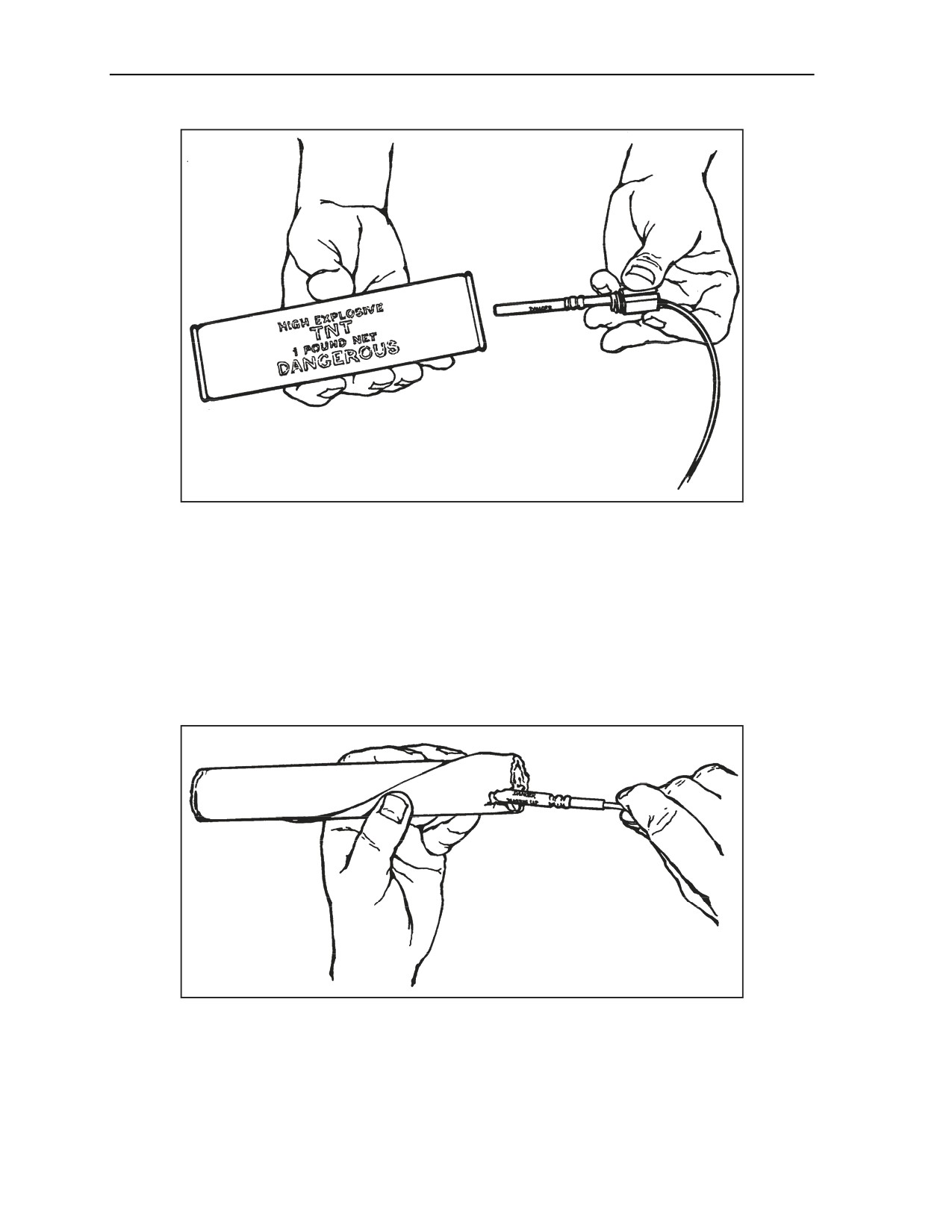
2-112. TNT blocks have threaded cap wells. A priming adapter is used to secure a high-strength blasting
cap or booster in the cap well of the TNT block as shown in Figure 2-48, page 2-62. When priming
adapters are not available, prime TNT blocks by inserting a high-strength blasting cap or a booster into the
cap well of the charge and secure it with tape.
11 July 2007
FM 3-34.214
2-61
Chapter 2
Figure 2-48. Priming a TNT Block With an MDI
MILITARY DYNAMITE
2-113. Military dynamite can be primed with MDI blasting caps or boosters using either the end- or side-
priming method. M2 crimpers or other nonsparking tools are used to make a cap well in one end of the
dynamite cartridge. If using the side-priming method, make the cap well in the side of the cartridge at one
end. The blasting cap or booster is inserted nearly parallel to the side of the cartridge. The explosive tip of
the cap should be near the middle of the cartridge. A blasting cap or booster is inserted into the cap well.
The shock tube, time fuse, or low-strength detonating cord is secured to the cartridge with tape to hold the
blasting cap or booster firmly in place (Figure 2-49). For quarry operations, see FM 3-34.465.
Figure 2-49. Priming M1 Dynamite With an MDI
M112 (COMPOSITION C4) DEMOLITION BLOCK
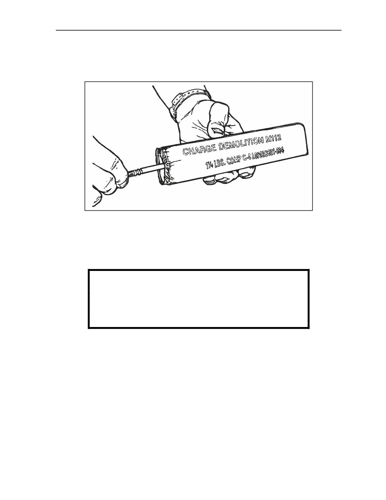
2-114. Use M2 crimpers or other nonsparking tools to make a hole in one end or on the side (at the
midpoint) of the demolition block. The hole should be large enough to hold a blasting cap or booster. Insert
2-62
FM 3-34.214
11 July 2007
Initiating Sets, Priming Methods, Firing Systems, and Modernized Demolition Initiators
a blasting cap or booster into the hole produced by the M2 crimpers. Do not force the blasting cap or
booster if it does not fit; make the hole larger. The blasting cap or booster is anchored in the demolition
block by gently squeezing the composition C4 plastic explosive around the blasting cap or booster. The
blasting cap or booster is secured by tape in the charge (Figure 2-50).
Figure 2-50. Priming a Composition C4 Demolition Block With an MDI
40-POUND CRATERING CHARGE
2-115. The 40-pound cratering charge is primed using one M151 or M152 booster and one M112
composition C4 or two M112 composition C4 as boosters attached to the side of the charge. Forty-pound
cratering charges should not be primed with blasting caps.
WARNING
Do not use the low-strength detonating cord of the M151 or M152
to lower 40-pound cratering charges into the holes. Failure to
comply could result in immediate personal injury or damage to
equipment.
M2A4 AND M3A1 SHAPED CHARGES
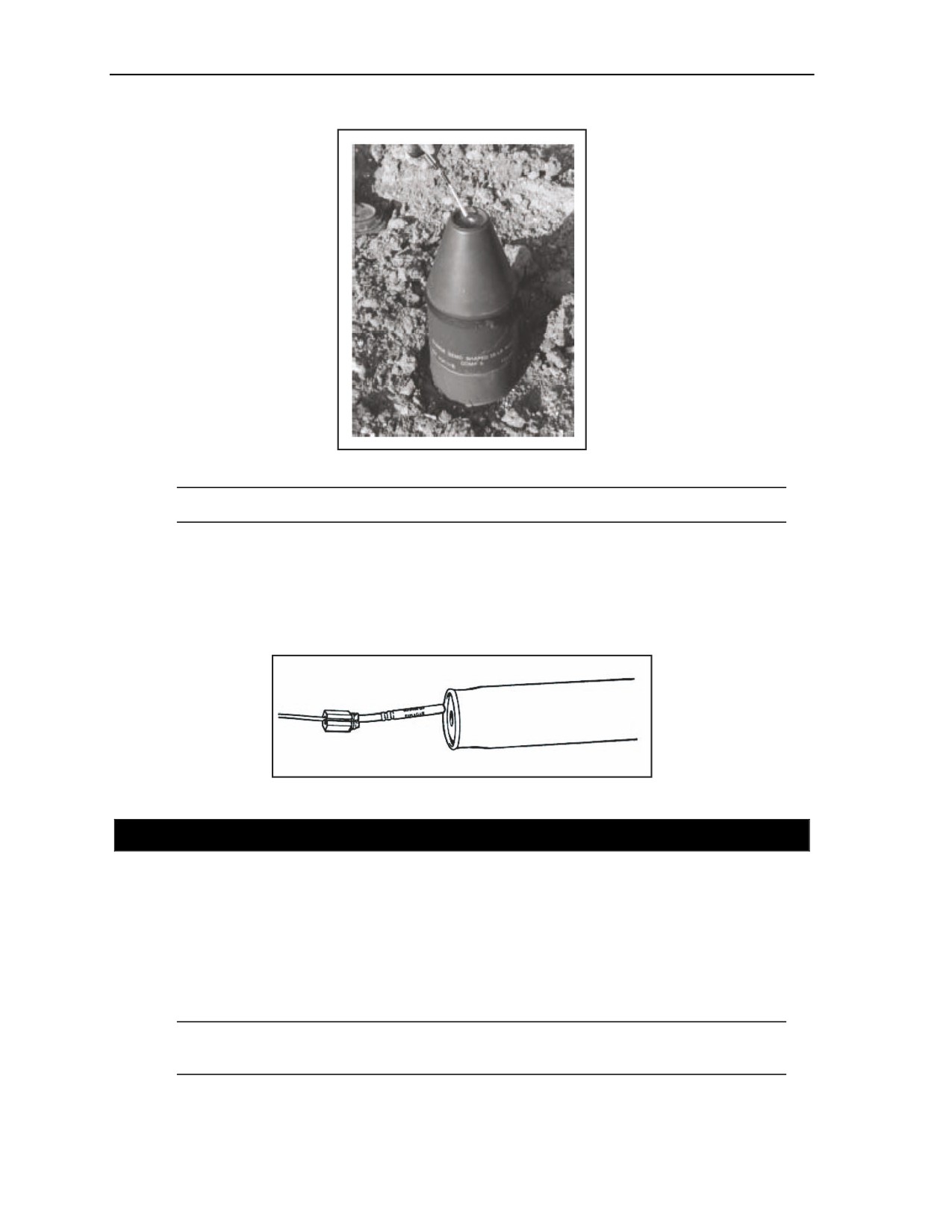
2-116. The M2A4 and M3A1 shaped charges have a threaded cap well at the top of the cone. A priming
adapter is used, if available, to secure a blasting cap or booster in the threaded cap well. If a priming
adapter is not available, use tape to secure the blasting cap or booster in the cap well (Figure 2-51,
page 2-64).
11 July 2007
FM 3-34.214
2-63
Chapter 2
Figure 2-51. Priming Shaped Charges With an MDI
Note. Charges will not be primed with blasting caps until the charges are placed on the target.
BANGALORE TORPEDO
2-117. The bangalore torpedo is primed using a blasting cap or a booster. Insert the blasting cap or
booster into the cap well in the end section of the charge, and secure it with a priming adapter. If a priming
adapter is not available, use tape to hold the blasting cap or booster firmly in place (Figure 2-52).
Figure 2-52. Priming the Bangalore Torpedo With an MDI
SECTION VI - INITIATING SETS AND FIRING SYSTEMS
INITIATING SETS
2-118. All MDI blasting caps and boosters can be used to initiate shock tube. Only use blasting caps or
boosters to initiate detonating cord or to prime and initiate explosive charges directly. MDI initiating sets
are used to initiate instantly. An M12, M13, M19, M21, and M23 or an M14 or M18 can be used to create a
delay. When using a combination (command and delayed) initiation system on the MDI, the command
initiation will be the primary initiation system, and the delay initiation will be the secondary initiation
system.
Note. Cover the secondary-initiation system blasting cap to reduce fragmentation hazards of the
cap.
2-64
FM 3-34.214
11 July 2007

Initiating Sets, Priming Methods, Firing Systems, and Modernized Demolition Initiators
2-119. If the primary initiating system fails, the secondary initiating system will function and initiate the
system when the time fuse burns down to the blasting cap. If the primary initiates the system, the secondary
blasting cap will detonate along with the other components of the firing system if it was connected to the
detonating cord. If the secondary blasting cap was connected to the shock tube or the low-strength
detonating cord, it will detonate when the time fuse burns down to the blasting cap. When using dual-delay
initiation systems, the shorter delay is the primary initiation system. When placing multiple charges, the
transmission line blasting caps and charges should be a sufficient distance apart to prevent fragments from
cutting other shock tube or low-strength detonating cord components before their planned ignition.
WARNING
Always observe the safe distances given in Chapter 6. Failure to
comply could result in immediate personal injury or damage to
equipment.
INSTANTANEOUS OR COMMAND INITIATION
2-120. To achieve the necessary safe distance from the explosive charges being emplaced, lay out one or
more M12s, M13s, M21s, or M23s. The blasting cap furthest from the initiation point is connected to the
MDI firing system or to the detonating cord ring main. When returning to the initiation point, visually
inspect the initiation system for possible misfire problems. This is the only test procedure for the MDI
initiation system. At the initiation point, the M81 igniter is secured to the M12 or M13 shock tube as
follows:
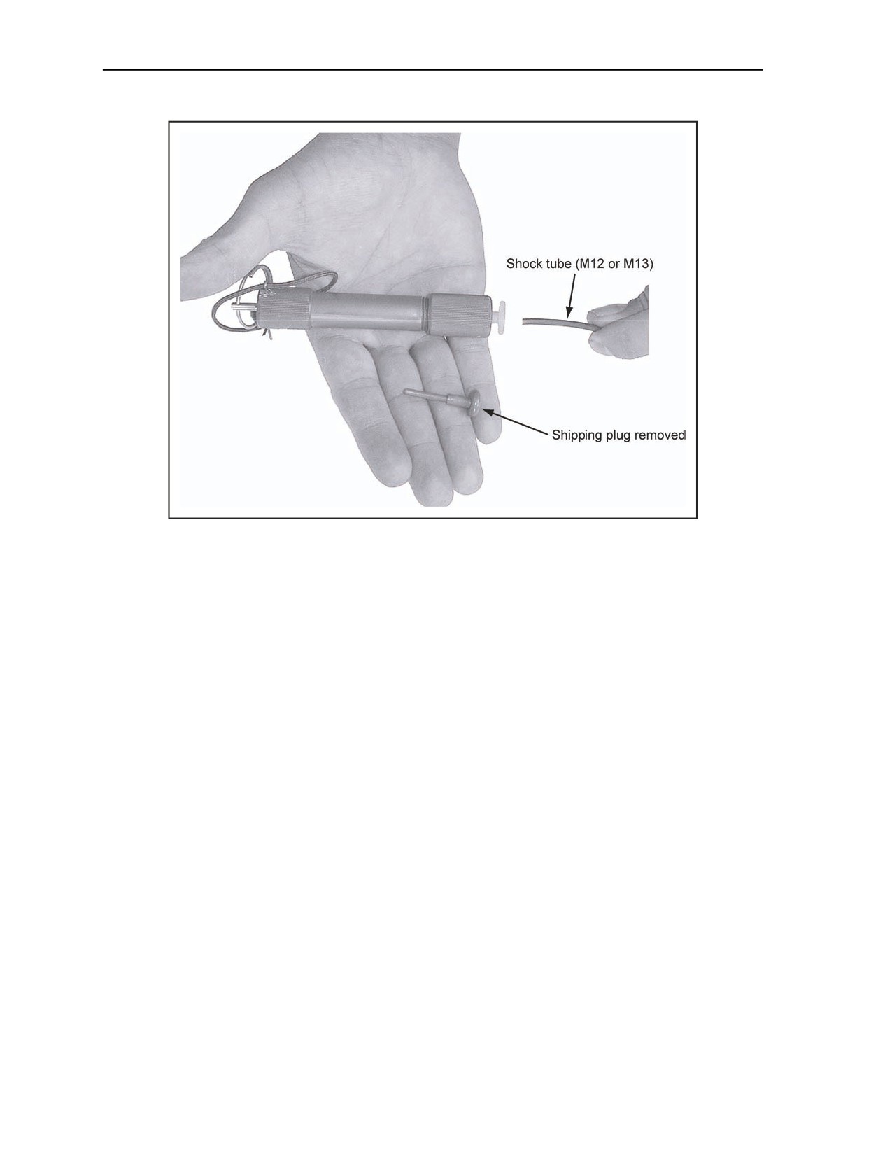
Loosen the M81 end cap three to four turns counterclockwise, and remove the hard, plastic
shipping plug. Pull the shipping plug out of the igniter ensuring not to remove the shock tube
reducer.
Cut off the crimped end of the shock tube at the desired length of the relay cap shock tube using
a sharp knife.
WARNING
Crimpers will not make a smooth enough cut to ensure that the
M81 will function the shock tube. Failure to comply could result in
immediate personal injury or damage to equipment.
Push the shock tube into the hole in the M81 end cap as far as it will go. Turn the igniter end cap
clockwise and finger tight to secure it in the device once the shock tube has seated (Figure 2-53,
page 2-66).
Ensure that all friendly personnel are at a safe distance from the explosive charge and that they
take appropriate cover.
Squeeze together the spread legs of the safety (cotter) pin. Use the safety pin cord to remove the
safety pin from the body of the igniter. Wear a leather glove, and grasp the igniter body firmly
with one hand, with the pull ring fully accessible to the other hand.
Actuate the igniter by sharply pulling its pull ring. Ensure that the pop of the igniter primer is
heard.
Note. The mechanism of the M81 is identical to that of the old M60 igniter. If the primer does
not fire, the M81 can be recocked and reactuated immediately. The igniter should be held firmly
and then the pull rod should be pushed back into the igniter until a click is heard or felt, and then
the pull ring should be pulled again sharply to actuate it. If the igniter primer fires, but the charge
does not, refer to Section VII, Misfires, in this chapter.
11 July 2007
FM 3-34.214
2-65
Chapter 2
Figure 2-53. M81 Fuse Igniter With a Shock Tube
DELAY INITIATION
2-121. The M14 delay blasting cap assembly has a 7 1/2-foot length of time fuse marked in nominal
1-minute increments giving a total delay of a nominal 5 minutes. Before attaching the M14 to the initiation
system, visually inspect the initiating sets for possible misfire problems. This is the only test procedure for
the MDI initiating set. The M14 is initiated by—
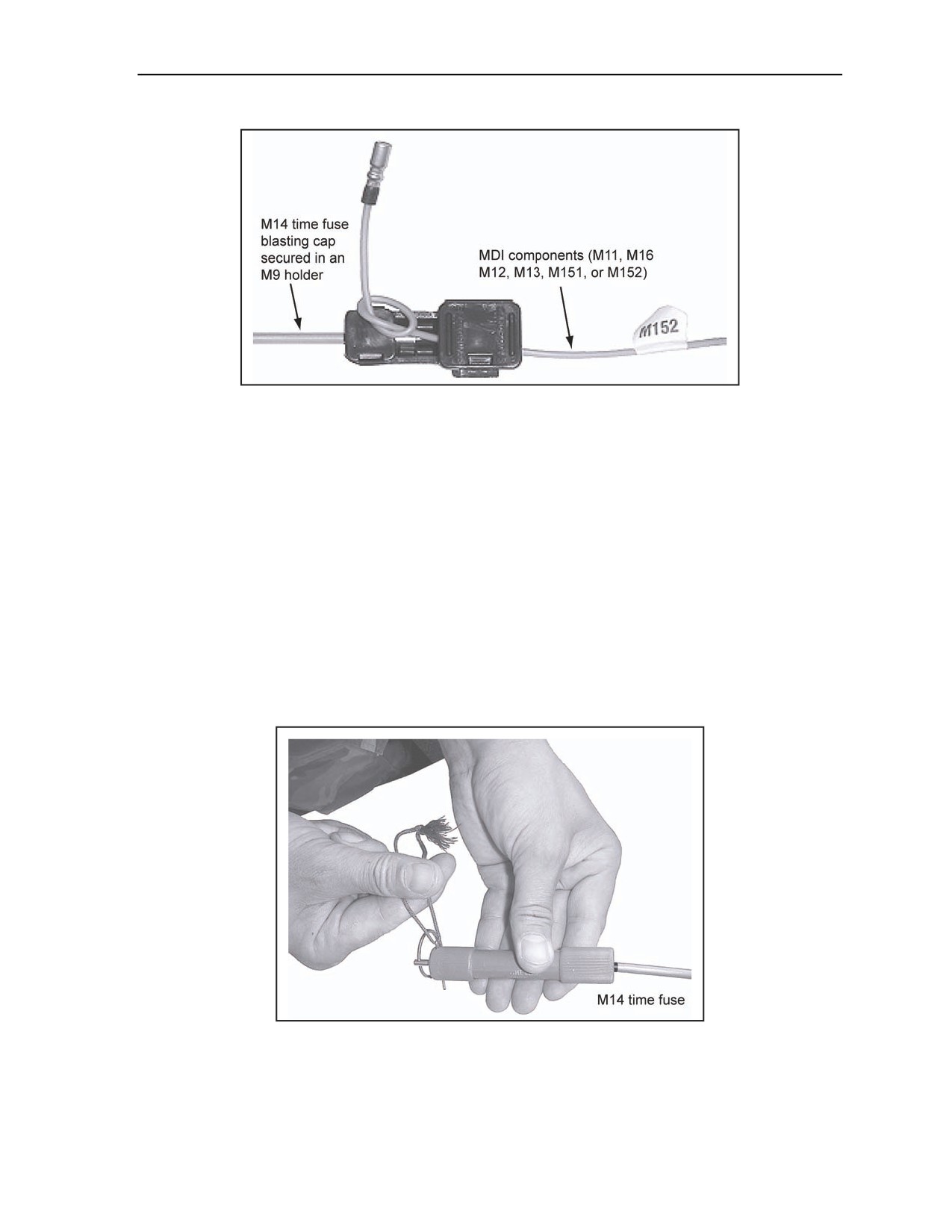
Step 1. Opening an M9 blasting cap holder.
Step 2. Inserting the M14 blasting cap.
Step 3. Snapping shut the smaller hinged flap to secure the M14.
Step 4. Placing up to five shock tubes, five low-strength detonating cords, or one strand of
detonating cord in the M9 holder if they are run straight through the M9 and are not looped.
Step 5. Tying the shock tube, low-strength detonating cord, or detonating cord ends into an
overhand knot.
Step 6. Placing the shock tube, low-strength detonating cord, or detonating cord in the M9
holder alongside the blasting cap and securing the M9 larger hinged holder flap.
Step 7. Securing the large flap with tape (Figure 2-54).
2-66
FM 3-34.214
11 July 2007
Initiating Sets, Priming Methods, Firing Systems, and Modernized Demolition Initiators
Figure 2-54. M9 Blasting Cap Holder in a Delay Initiation
2-122. A M14 time fuse is installed as follows:
Step 1. Use a sharp knife to cut 1/4 inch of the time fuse and the metal seal from the free end of
the M14 time fuse (if the maximum 5-minute delay is required). Cut at the marked bands to
reduce the delay, if so desired. Ensure that the delay on the time fuse allows for withdrawal to a
safe distance or allows time to take appropriate cover.
Step 2. Loosen the M81 end cap three to four turns counterclockwise so the hard, plastic
shipping plug can be easily removed. Pull the shipping plug and shock tube reducer out of the
igniter.
Step 3. Secure an M81 fuse igniter to the freshly cut end of the M14 time fuse (Figure 2-55).
Step 4. Squeeze the spread legs of the safety (cotter) pin together. Use the safety pin cord to
remove the safety pin from the body of the igniter. Wear a leather glove and grasp the igniter
body firmly with one hand, with the pull ring fully accessible to the other hand. Pull the igniter
pull ring sharply to actuate.
Step 5. Ensure that smoke is coming from the fuse or out of the vent hole in the igniter.
Step 6. Remove the igniter, and withdraw to a safe distance or to appropriate cover.
Figure 2-55. M81 Fuse Igniter With an M14 Time Fuse Installed
11 July 2007
FM 3-34.214
2-67

Chapter 2
SPECIAL CONDITIONS
2-123. The ambient temperature and the altitude of the site have an impact on the operation of the MDI.
Cold weather and high altitudes will extend the delay times on the M14 and M18. Precautions can be taken
when using MDI in extreme cold temperatures and/or high altitudes by dual-priming and dual-initiating the
charges to ensure proper initiation. When using MDI for ice demolitions, the same precautions must be
taken with one addition; if the charges are to be placed in the ice or under water in extreme cold conditions,
the same rules apply as if the target were stemmed or tamped. For these types of missions, use detonating
cord for priming and branchline construction.
Note. The M14 and M18 time-blasting fuses gives about a 5-minute delay and 20-minutes,
respectively, between lighting the fuse and initiating the detonator. Like the standard M700 fuse,
the burning time will vary with temperature and altitude. For example, operating at an altitude of
12,000 feet in cold weather will extend the delay time significantly. When exact detonation
times are required, command-detonation methods should be considered.
WARNING
When using an MDI in extreme cold temperatures and/or high
altitudes, dual-prime and dual-initiate the charges. Failure to
comply could result in immediate personal injury or damage to
equipment.
MODERNIZED DEMOLITION INITIATOR FIRING SYSTEMS
2-124. With the introduction of MDI components, there are two types of firing systems: a stand-alone and
a combination firing system. Both systems can be emplaced as single- or dual-firing systems. The choice of
which system to use for a particular demolition mission is left to the experience of the engineer
commander. However, the combination firing system is the preferred method for reserved demolition
targets. Whenever handling MDI components with blasting caps or boosters outside of their original
packaging, ensure that they are inserted into a foam protective cap or an M9 holder to prevent damage.
DISPOSAL
2-125. After the charges have been successfully fired, the unit commander is responsible for ensuring the
proper disposal of the residue. The used shock tube is nonrecyclable plastic and may be sent directly to an
approved landfill. However, the blasting cap residual is considered hazardous waste and must be removed
from the shock tube and disposed of according to local policy. Commanders must coordinate with the local
Directorate of Engineering (Department of Public Works) and/or the local Defense Reutilization and
Marketing Office (DRMO) for local disposal guidance and landfill information.
WARNING
Do not dispose of used shock tubes by burning them because of
the potentially toxic fumes given off from the burning plastic.
Failure to comply could result in immediate personal injury or
damage to equipment.
STAND-ALONE SYSTEM
2-126. The stand-alone firing system is one in which the initiating sets and transmission and branchlines
are constructed using only MDI components and the explosive charges are primed with MDI blasting caps
2-68
FM 3-34.214
11 July 2007
Initiating Sets, Priming Methods, Firing Systems, and Modernized Demolition Initiators
or boosters. It is important to ensure that the firing system is balanced. All charges must have the same
distance in the shock tube length and the low-strength detonating cord from the firing point to the charge.
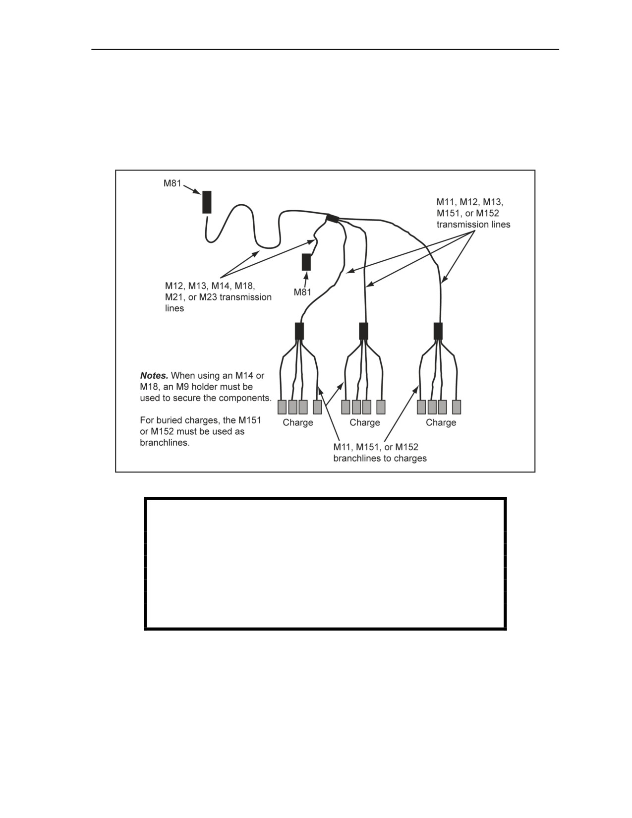
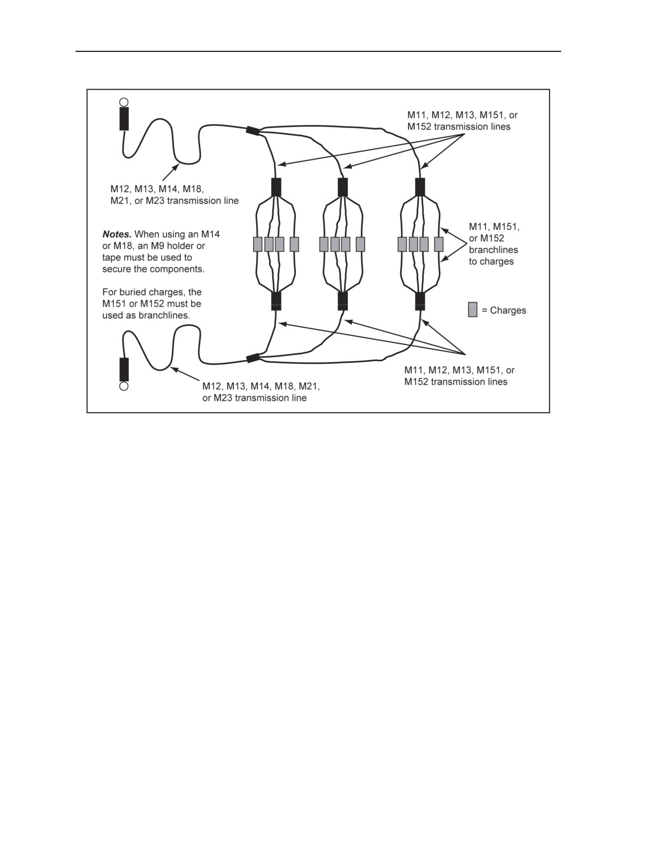
Figure 2-56 shows the MDI single-firing system and Figure 2-57, page 2-70, shows the MDI dual-firing
system.
2-127. The disadvantages of a single-firing system are that if the transmission line is cut, charges down
line from the cut will not detonate. If there is a possibility of the transmission lines being cut (for example,
through artillery fires), a second firing system should be added as shown in Figure 2-57.
Figure 2-56. MDI Single-Firing System (Single-Primed and Dual-Initiated)
WARNING
When making multishock tube installations, ensure that the shock
tubes are protected from the effects of the nearby relay caps and
charges. The shrapnel produced by a cap or charge could easily
cause a misfire (partial or complete). When there are many shock
tubes involved in a shot, they should be carefully placed away
from the junction. Failure to comply could result in immediate
personal injury or damage to equipment.
2-128. The stand-alone MDI firing system is used for all types of demolition missions, including bridge
demolitions. The MDI firing system can be used to initiate reserved demolition targets. However, only the
M151 or M152 may be used to prime charges. Under current internationally agreed upon doctrine, charges
cannot be primed with blasting caps until a change of readiness from state 1 (safe) to state 2 (armed) is
ordered. Priming every charge with MDI blasting caps at this critical moment would take a considerable
amount of time and be unacceptable to the maneuver commander. Priming charges with MDI M151 or
MDI M152 components or detonating cord are the required methods for reserve demolition targets. The
charges in this case are now dual-primed, the transmission line is laid in the opposite direction of the first
transmission line, and the system is a balanced system.
11 July 2007
FM 3-34.214
2-69
Chapter 2
Figure 2-57. MDI Dual-Firing System (Dual-Primed and Dual-Initiated)
CONSTRUCTION SEQUENCE OF A MODERNIZED DEMOLITION INITIATOR USING A SHOCK
TUBE
2-129. The demolition site should be thoroughly reconnoitered before emplacing explosive charges on the
firing system. The following steps should be used:
Step 1. Identify the firing point, and observe the safe distances as given in Chapter 6.
Step 2. Emplace and secure primed explosive charges on the target.
Step 3. Begin with the set of explosive charges furthest from the firing point, and place a
sandbag or other easily identifiable marker over the transmission line blasting cap. Use an M11
or M152 if the distance between the sets of charges is less than 30 feet. Use an M151 if the
distance is less than 10 feet.
Step 4. Attach branchlines from the primed explosive charges to the transmission line using the
attaching method as shown in Figure 2-46, page 2-57. Secure the transmission and branchlines
by taping all the holders closed.
Step 5. Unreel the transmission line to the firing point. Achieve the necessary safe distance by
using several M12s, M13s, M21s, or M23s if needed. Use an M14 or M18 as an ignition element
of a transmission line to provide time to reach a safe distance without the need to lay and
connect multiple M12s, M13s, M21s, and M23s spooled components as transmission lines.
2-70
FM 3-34.214
11 July 2007

Initiating Sets, Priming Methods, Firing Systems, and Modernized Demolition Initiators
Note. To effectively prevent a misfire, the shock wave in the shock tube must travel the same
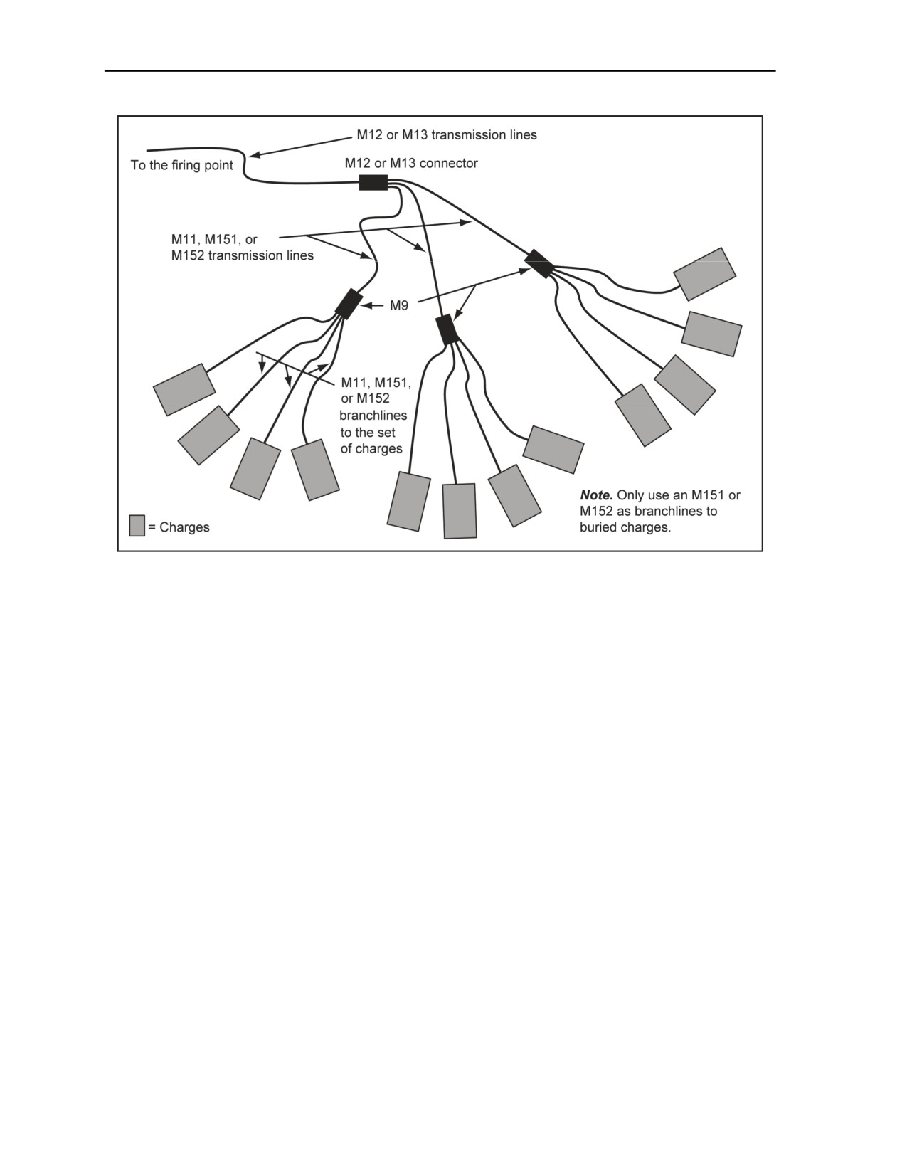
distance to all charges. No more than five M11, M151, or M152 branchlines can be connected to
the transmission line blasting cap holder. If there are more than five charges, group the
branchlines from the charges, and connect them to the M9s blasting cap holder of another M11,
M151, or to an M152 branchline. The branchline is connected to the transmission line blasting-
cap holder as shown in Figure 2-46, page 2-57. The transmission and branchlines are secured by
a large, hinged flap and the flap is secured with tape.
Step 6. Perform a visual inspection of the firing system for possible misfire indicators while en
route to the firing point.
Step 7. Initiate the system at the firing point using the procedures in paragraph 2-121.
CONSTRUCTION SEQUENCE OF A MODERNIZED DEMOLITION INITIATOR USING AN M151
OR AN M152
2-130. The boosters are factory-crimped onto low-strength detonating cord. The booster is used to prime
charges that are either buried or aboveground by substituting, not eliminating, the present use of standard
detonating cord as a branchline or to prime charges. When an M151 or M152 is removed from an original
shipping container, a foam protector should be installed on the booster. As low-strength detonating cord is
used, additional procedures are involved in the use of an M151 and M152. These procedures include—
Removing any tape used to bundle an M151 or M152.
Spreading the low-strength detonating cord between the primed charge and the M9 holder of the
transmission line when charges are in the same general area.
Avoiding conditions where one or more cords are running alongside or twisted with other cords
or crossovers any low-strength detonating cord.
Ensuring that the cords are in contact with a blasting cap or booster.
2-131. Thoroughly reconnoiter the demolition site before emplacing explosive charges on the firing
system. Use the following steps:
Step 1. Identify the firing point, and observe the safe distances as given in Chapter 6.
Step 2. Emplace and secure primed explosive charges on the target.
Step 3. Begin with the set of explosive charges farthest from the firing point, and place a
sandbag or other easily identifiable marker over the transmission line blasting cap. Use an M11
or M152 if the distance between the sets of charges is less than 30 feet. Use an M151 if the
distance is less than 10 feet.
Step 4. Attach branchlines from the primed explosive charges to the transmission line. See
Figure 2-58, page 2-72. The attaching method is shown in Figure 2-46. Secure the transmission
and branchlines by taping all the holders closed.
Step 5. Unreel the transmission line to the firing point. Use several M12s, M13s, M21s, or M23s
to achieve the necessary safe distance needed. Use an M14 or M18 as an ignition element of a
transmission line to provide time to reach a safe distance without laying and connecting multiple
M12s, M13s, M21s, and M23s spooled components as transmission lines.
Step 6. Perform a visual inspection of the firing system for possible misfire indicators while en
route to the firing point.
Step 7. Initiate the system at the firing point using the procedures in paragraph 2-121.
11 July 2007
FM 3-34.214
2-71
Chapter 2
Figure 2-58. MDI Branchline Array
COMBINATION FIRING SYSTEM
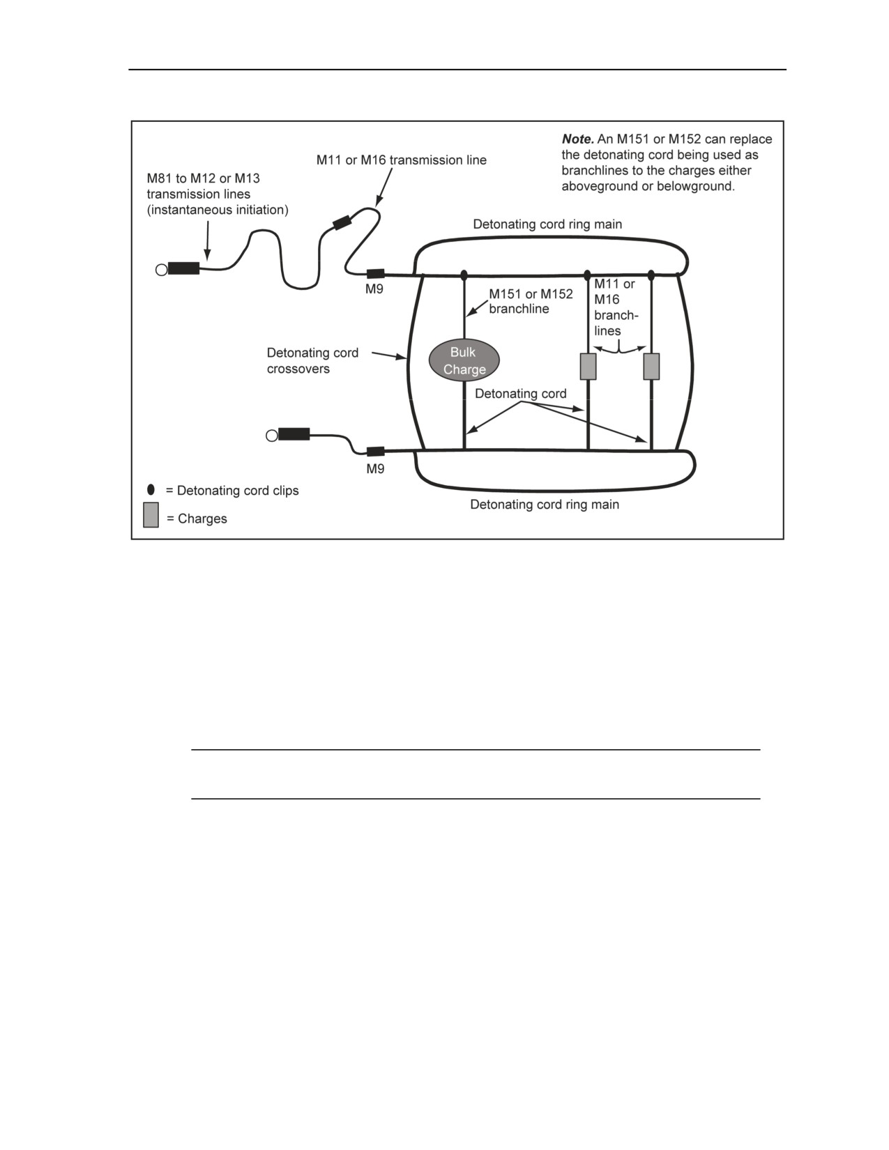
2-132. A combination firing system is one which consists of the MDI initiating set, either a detonating
cord line used as a line or ring main and branchlines that can be either MDI shock tube components or
booster components used as branchlines (Figure 2-59).
2-72
FM 3-34.214
11 July 2007
Initiating Sets, Priming Methods, Firing Systems, and Modernized Demolition Initiators
Figure 2-59. Combination (MDI and Detonating Cord) Firing System (Dual)
2-133. Use the combination (MDI and detonating cord) firing system for all types of demolition missions.
It combines the advantages of MDI components with the simplicity and flexibility of detonating cord. The
combination firing system is the preferred method for reserved demolition targets, underwater operations,
and operations where subsurface-laid charges are used.
CONSTRUCTION SEQUENCE FOR MODERNIZED DEMOLITION INITIATOR SHOCK TUBE
COMPONENTS AND DETONATING CORD
2-134. Thoroughly reconnoiter the site before emplacing explosive charges on the firing system. Use the
following steps:
Note. M151s or M152s can be used to replace detonating cord when used as branchlines to
charges placed either aboveground or belowground.
Step 1. Identify the firing point, and observe the safe distances as given in Chapter 6.
Step 2. Emplace and secure the primed explosive charges on the target.
Step 3. Construct detonating cord line or ring mains according to the procedures in Section III,
of this chapter.
Step 4. Cover the blasting cap of the transmission line with a sandbag or another easily
identifiable marker at the connection between the detonating cord line and ring main to the MDI
initiating set.
11 July 2007
FM 3-34.214
2-73
Chapter 2
Step 5. Tie in any detonating cord branchlines to the line or ring main. Clip the branchlines to
the detonating cord line or ring main using the attached detonating cord clip if priming with
MDI. Do this by—
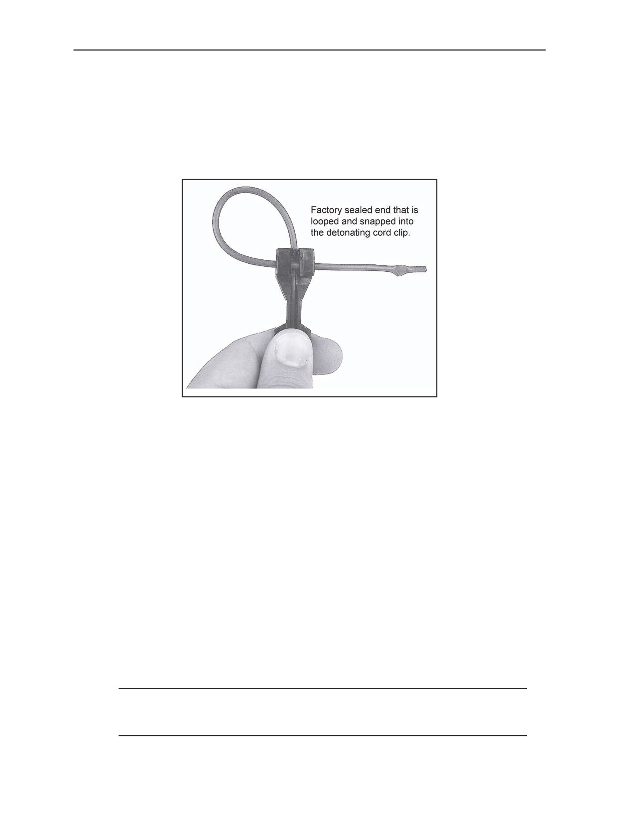
Looping the shock tube around and into the detonating cord clip (Figure 2-60).
Pulling the shock tube tight to prevent the detonating cord clip from slipping.
Clipping the detonating cord line or ring main into the detonating cord clip.
Laying the branchlines toward the charges if an M11 is used.
Figure 2-60. MDI Detonating Cord Clip
Step 6. Lay out an M11, M151, or M152 with an M9 installed as a transmission line from the
detonating cord ring main to the transmission line.
Step 7. Attach the M11, M151, or M152 to the holder on the transmission line blasting cap
holder, and secure with tape.
Step 8. Tie an overhand knot in the detonating cord of the ring main, and place it into the M9
blasting cap holder. Secure the large flap with tape.
Step 9. Perform a visual inspection of the entire firing system for any flaws, which might cause
a misfire.
Step 10. Initiate the system at the firing point using the procedures in paragraph 2-121.
SHOCK TUBE SPLICING
2-135. The MDI shock tube components are extremely reliable because all the components are sealed.
Unlike standard, nonelectric priming components, they cannot be easily degraded by moisture. Cut shock
tubes make the open ends vulnerable to moisture. Dampened explosive film on the inside of the shock tube
will stop a detonation from going beyond such a damp spot. Care should be taken when cutting and splicing
the shock tube. When cutting the shock tube, make a temporary moisture seal by bending it 2 inches onto
itself from the cut and taping it together along the open end with electrical tape. Splicing tubes are used to
repair a break in the shock tube of a transmission or branchline (for example, caused by shrapnel from
artillery fire). Every splice in the shock tube reduces the reliability of the firing system. The number of
splices in a shock tube line should be kept to as few as practicable.
Note. A fully sealed MDI component should be used to replace the broken shock tube. If a fully
sealed MDI component is not available, splicing is used as a last resort. When conducting water
or diving demolition missions, do not splice the shock tube.
2-74
FM 3-34.214
11 July 2007
Initiating Sets, Priming Methods, Firing Systems, and Modernized Demolition Initiators
2-136. The following procedures are the proper way to splice the shock tube:
Step 1. Use a sharp knife to make a square cut about 3 feet from the previously cutoff end of the
shock tube, whether or not it was knotted according to the guidance above. Immediately seal off
the shock tube remaining on the spool by bending 2 inches of the shock tube end over on itself
and taping it in place to provide a temporary moisture seal. Tie a knot if no tape is available.
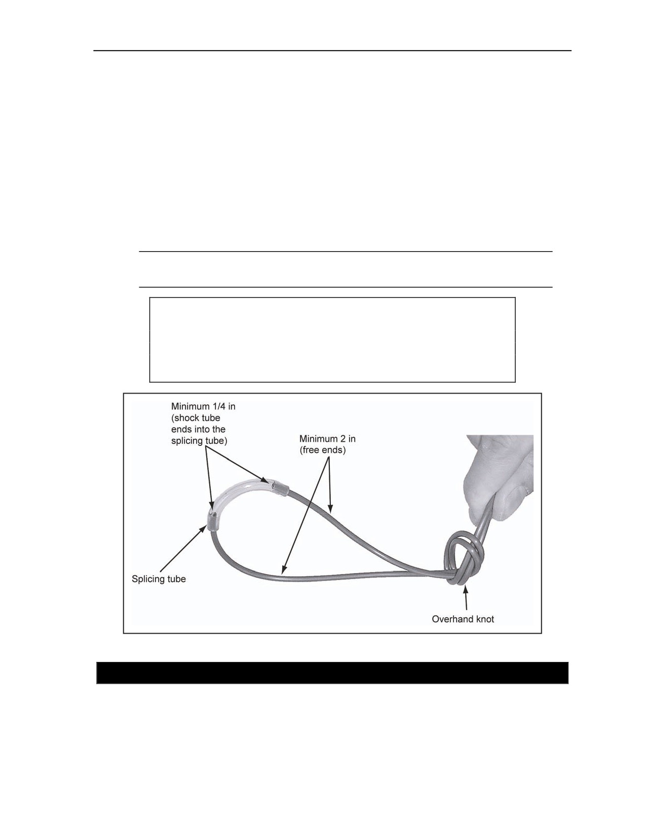
Step 2. Tie loosely the two shock tube ends to be spliced together in an overhand knot. Leave at
least 2 inches free at the end of each shock tube beyond the knot.
Step 3. Pull the shock tube lightly to tighten the knot, but not so tight as to significantly deform
the shock tube in the knot.
Step 4. Push one of the free shock tube ends to be spliced firmly into one of the precut splicing
tubes at least 1/4 inch.
Step 5. Push the other shock tube end firmly into the other end of the splicing tube at least
1/4 inch (Figure 2-61).
Note. It is not necessary for the two ends of the shock tube to meet; the detonation wave in the
shock tube will still generate over a small gap.
CAUTION
Taping two cut ends of the shock tube together does not make a
reliable splice. Personal injury or damage to equipment may result
from long-term failure to follow correct procedures.
Figure 2-61. Splicing a Shock Tube
SECTION VII - SAFETY PROCEDURES
MODERNIZED DEMOLITION INITIATOR CONSIDERATIONS
2-137. When conducting training and missions with the MDI, follow the general safety considerations for
demolitions as given in Chapter 6 and DA Pamphlet 385-63. When MDI components are removed from
their original packaging, install a foam protector onto the blasting cap or booster. Misfires occur when—
11 July 2007
FM 3-34.214
2-75

Chapter 2
The shock tube is cut using crimpers.
The M81 fuse igniter is not properly connected to the shock tube before initiation or the shock
tube is pulled after being secured in the M81.
The shock tube is cut by shrapnel during the initiation process.
The shock tube is incorrectly inserted into the holders on the M12 or M13 blasting caps or into
the M9 holder.
An overhand knot is not used to secure the spliced area. A splice without a knot can separate by
a small accidental tug on the shock tube.
2-138. MDI components, with factory-crimped blasting caps attached to a shock tube, in their original
packaging and subpackaging are marked according to Department of Transportation hazard class
explosives requirements. These items can be transported with other explosives provided they are
compatible. See DA Pamphlet 385-64 to identify the classes of explosives that can be transported in the
same vehicle.
MODERNIZED DEMOLITION INITIATOR MISFIRES
2-139. Working on or near a misfire is the most hazardous of all blasting operations. A misfire in the MDI
system is extremely rare if the following procedures are used:
Prepare and emplace all components of the firing systems. Use dual-firing systems where
appropriate. Ensure that the detonating cord, shock tube, or low-strength detonating cord in the
blasting cap holder is in contact with the blasting cap. Do not mix the detonating cord, shock
tube, or low-strength detonating cord in the same M9 holder.
Mark or cover MDI blasting caps with sandbags or other clearly identifiable markers to prevent
personnel from damaging the caps during setup.
Emplace and prime all charges safely.
Prime all buried charges with an M151, M152, or detonating cord.
Perform any tamping operation with care to avoid damage to the charges and the priming
system. Always tamp with a nonsparking tool.
Initiate charges according to the correct technique.
Inspect visually the firing system before initiation.
DANGER
Do not handle misfires down range until the required 30-minute
waiting period for both primary and secondary initiation systems
has elapsed and other safety precautions have been taken.
Failure to comply may cause death or permanent injury.
2-140. The most common cause of a misfire in a shock tube firing system is the initiating element, usually
an M81 igniter. The following misfire procedures are for both command-initiated and delay-initiated
systems(Figure 2-62):
A failure with the M81 will occur if the primer does not fire. If, after two retries, the M81 does
not result in it firing, cut the shock tube, replace the igniter with a new one, and repeat the firing
procedure.
Another misfire mode for the M81 is that the primer fires but blows the shock tube out of its
securing mechanism without it firing. This is usually due to the shock tube not having been
properly inserted and secured in the igniter. To correct this problem, cut a minimum of 3 feet
from the end of the shock tube. It is recommended that the shock tube be checked for the
presence of fine explosive powder following step 1 in the next paragraph. If powder is present,
replace the igniter and repeat the firing procedure.
2-76
FM 3-34.214
11 July 2007
Initiating Sets, Priming Methods, Firing Systems, and Modernized Demolition Initiators
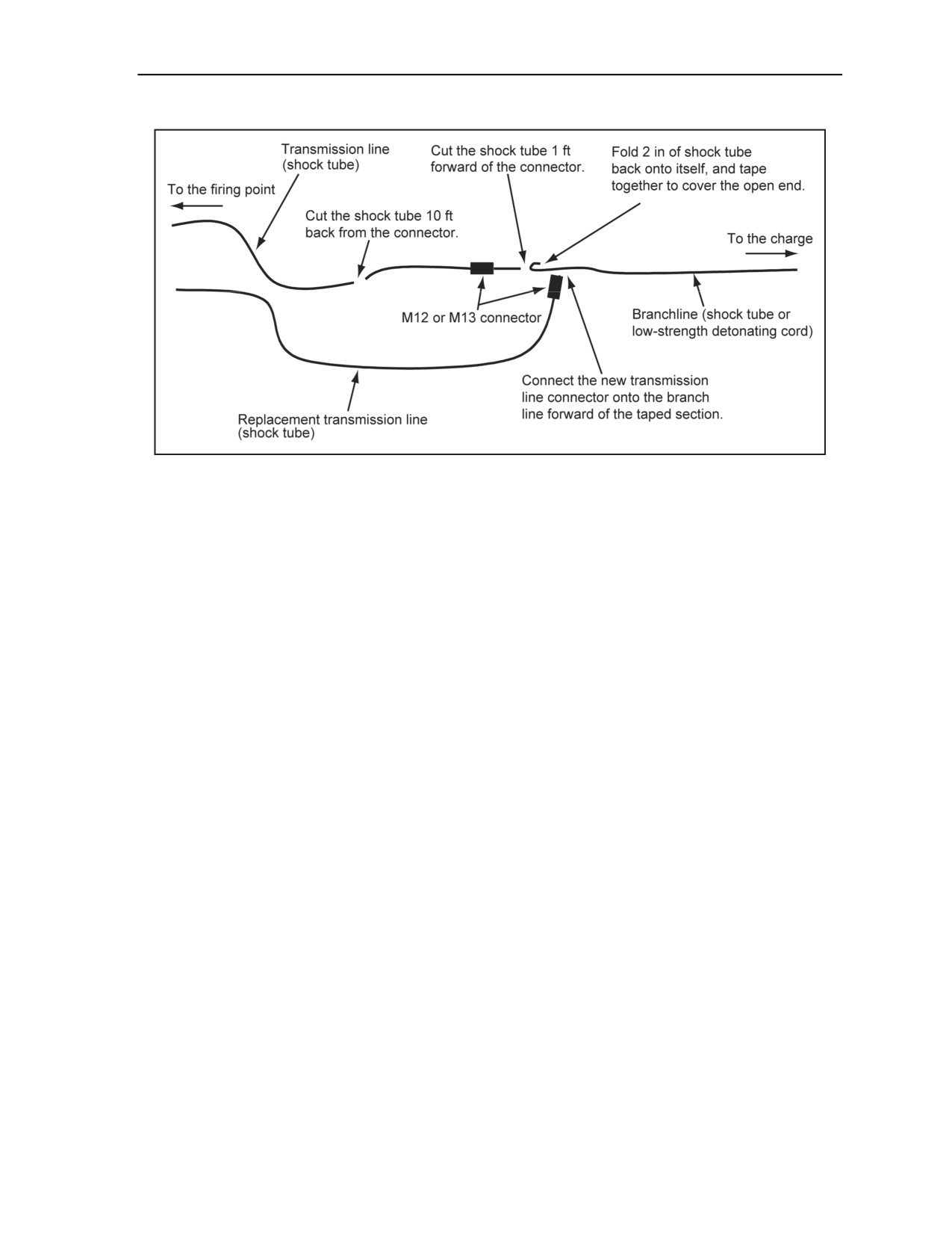
Figure 2-62. MDI Misfire Procedures
2-141.
The following steps are used to correct misfire problems:
Step 1. If the igniter appears to have functioned properly (the primer pops or smokes), but the
charge did not fire, cut off the first 6 inches of shock tube and discard. Then cut a 1-foot section
from the shock tube. Hold the 1-foot piece of shock tube so that one end is over the palm of your
hand, then blow through the other end. If no powder is present, proceed to step 2. If a gray or
silver powder is blown from the shock tube, it has not fired. In this case, install a new igniter on
the freshly cut end of the shock tube, and repeat the firing procedure. If detonation does not
occur, proceed to step 3.
Step 2. If the igniter or initiating element functioned properly and no powder was blown from
the shock tube in the previous step or its flash was seen, observe the burn time plus 30 minutes
before going downrange.
Step 3. After waiting the burn time plus 30 minutes, proceed downrange and check all the
components in the firing system. The most likely cause of a misfire is the incorrect placement of
the shock tube in the blasting cap holders (for example, the blasting cap detonated but failed to
initiate the shock tube of the next down-line MDI component). If a blasting cap has not fired, it
is likely that the shock tube was not initiated by the up-line blasting cap. To determine if the
shock tube has fired at a particular point, perform step 1 with a 1-foot section of shock tube cut
from the suspect area.
Step 4. If the shock tube still contains the explosive dust, attach a new component by cutting the
shock tube down line from the defective shock tube 1 foot past the blasting cap holder. Seal the
shock tube by bending it 2 inches from the cut and taping it. On the defective tube, move down
and cut it 10 feet from the blasting cap. Remove and dispose of the defective shock tube and cap
according to local misfire policies. Then, lay out the shock tube of the replacement component
back to the firing point, and repeat the firing sequence when it is safe to do so.
Step 5. If the shock tube contains no explosive dust because it has been fired, the problem is
probably with the blasting cap. The shock tube is cut down line from the defective blasting cap
1 foot past the blasting cap holder. Then, seal the shock tube by bending it 2 inches from the cut
and taping it. On the shock tube of the defective blasting cap, move down and cut it 10 feet from
the blasting cap. Remove and dispose of the defective shock tube and cap according to local
misfire policies. Then, lay out the shock tube of the replacement component back to the firing
point, and repeat the firing sequence when it is safe to do so.
11 July 2007
FM 3-34.214
2-77

Chapter 2
DANGER
Never yank or pull hard on the shock tube. This may actuate the
blasting cap. Failure to comply may cause death or permanent
injury.
Step 6. If the first component of the firing train was not the one that failed, check out each
succeeding component until the failed one is found. Then, replace the failed or fired relay
components back to the initiating site as in steps 4 and 5.
Step 7. If the failed component appears to be the final high-strength blasting cap or booster,
replace if it is easily accessible. If it is used to prime an explosive charge, do not disturb it. Then,
place a new, primed 1-pound explosive charge next to the misfired charge and detonate it when
it is safe to do so.
Step 8. If the charges were primed with MDI M151 or MDI M152 components and buried,
follow the above misfire procedures to the low-strength detonating cord of an MDI M151 or
MDI M152. If the transmission line blasting cap has failed to function, use a nonsparking tool to
cut the low-strength detonating cord 1 foot past the failed transmission line blasting cap. Then,
walk back 10 feet from the defective blasting cap, and cut the transmission line shock tube.
Remove the defective shock tube, failed cap, and the length of low-strength detonating cord is
and dispose of them according to local misfire procedures. Lay out a replacement transmission
line to the firing point and then connect the remaining low-strength detonating cord to the
transmission line holder. Repeat the firing sequence to detonate the charge. If the buried charge
has failed to detonate, but the booster cord has functioned to the surface of the buried charge,
follow the procedures in Chapter 6, Section III.
SECTION VIII - MODERNIZED DEMOLITION INITIATOR USE WITHIN
COMMON DEMOLITION MISSIONS
FIRING SYSTEMS PLANNING
2-142. The MDI system has many components that make up a firing system. Because of this, it is critical
during the planning and resourcing phase of the operation that the firing system be planned in detail. The
process of planning the firing system from the charge to the firing point is critical to the success of the
mission. Demolition site reconnaissance is required and precise numbers of shock tube, holders, and other
devices must be determined before executing the demolition mission. All residue must be collected and
disposed of whenever possible. This is both an environmental and a tactical necessity.
2-143. A number of missions require charges to detonate simultaneously. To assure this, branchlines of
equal length must be attached to the initiating cap or booster or detonating cord ring main if used. Making
branchlines as short as is practical will further improve the simultaneous detonation of the charges. For
example, if the farthest distance for one of three branchlines is 15 feet, measure the three lines, tie an
overhand knot at this point, and connect the transmission line between the knot and the charge or move all
three J hooks to that point and connect.
STEEL-CUTTING CHARGES
2-144. Steel-cutting charges should be emplaced according to the procedures outlined in Chapter 3. See
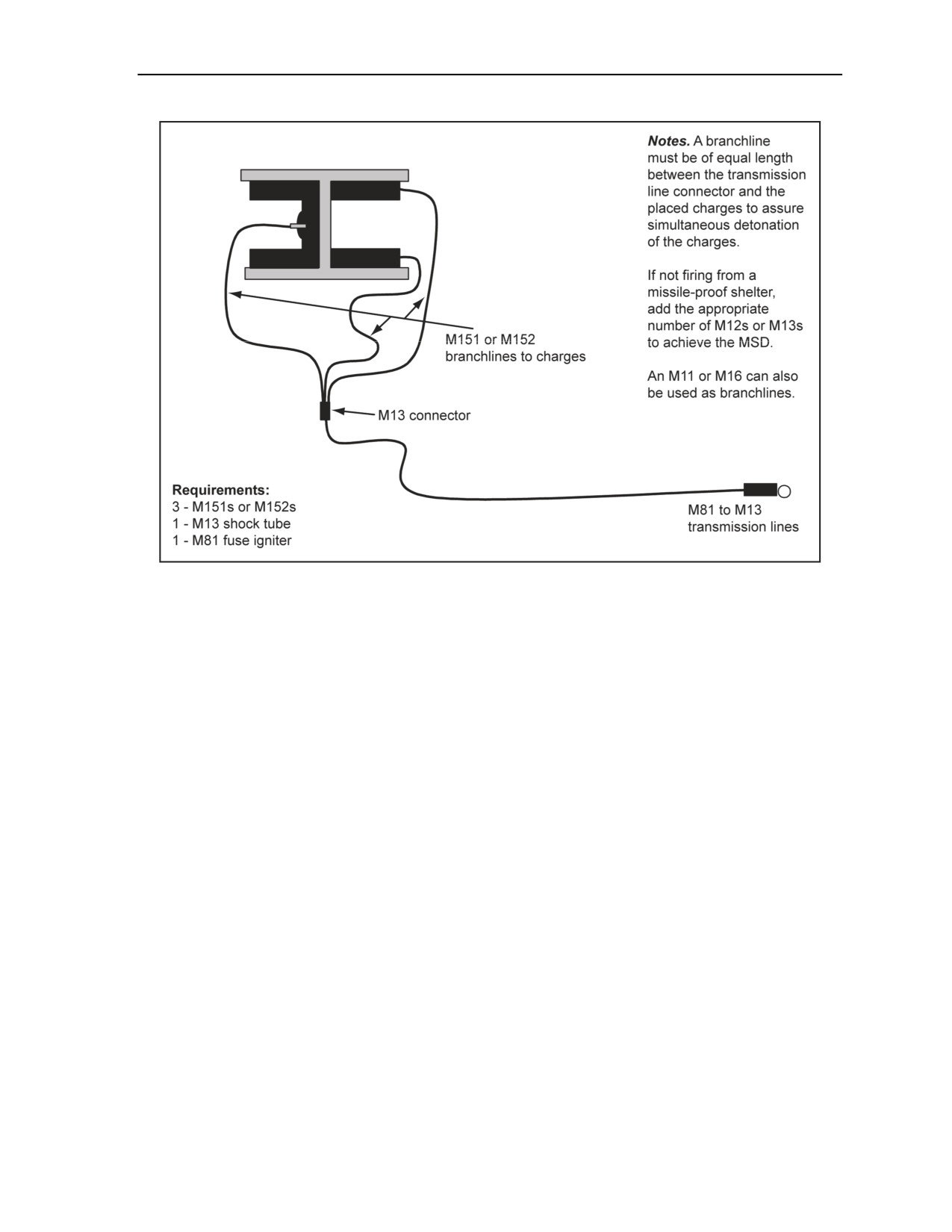
Figure 2-63 for an example of steel I beam cutting charges.
2-78
FM 3-34.214
11 July 2007
Initiating Sets, Priming Methods, Firing Systems, and Modernized Demolition Initiators
Figure 2-63. Steel I Beam Cutting Charges
BRIDGE DEMOLITION CHARGES
2-145. When a demolition team has a bridge target assigned, planning should include a review of the MDI
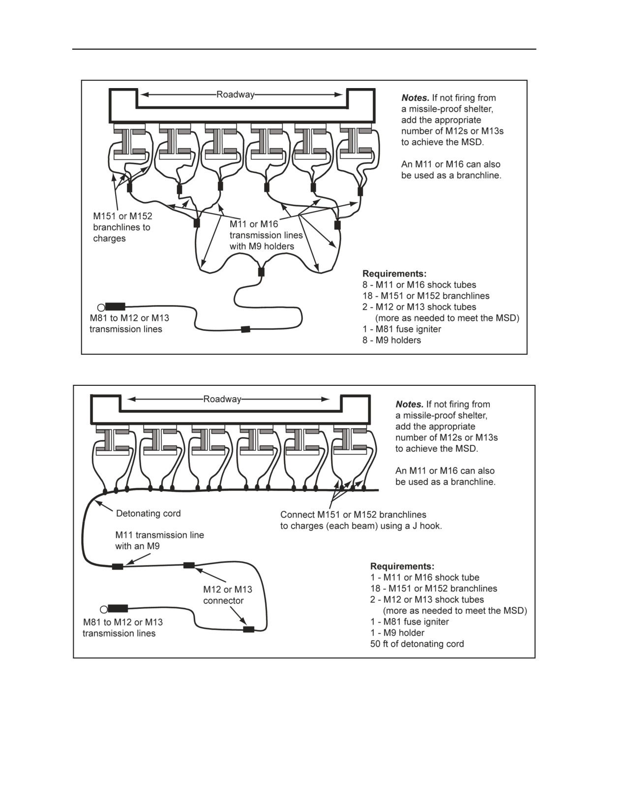
characteristics in simultaneous detonation of charges, branchlines, or equal distant branchlines placement in
holders. See Figure 2-64, page 2-80, and Figure 2-65, page 2-80, for examples of bridge demolition
charges.
11 July 2007
FM 3-34.214
2-79
Chapter 2
Figure 2-64. Bridge Demolition Charges (MDI-Balanced Firing System)
Figure 2-65. Bridge Demolition Charges (MDI or Detonating Cord Combination)
2-80
FM 3-34.214
11 July 2007
Initiating Sets, Priming Methods, Firing Systems, and Modernized Demolition Initiators
BRIDGE DEMOLITION CHARGES AND CONSTRUCTION
SEQUENCE USING SHOCK TUBE COMPONENTS
2-146. Bridge demolition charges should be emplaced according to the procedures outlined in Chapter 4.
TIMBER-CUTTING CHARGES
2-147. Timber-cutting charges should be emplaced and primed according to the procedures outlined in
Chapter 3.
EXTERNAL TIMBER CHARGE
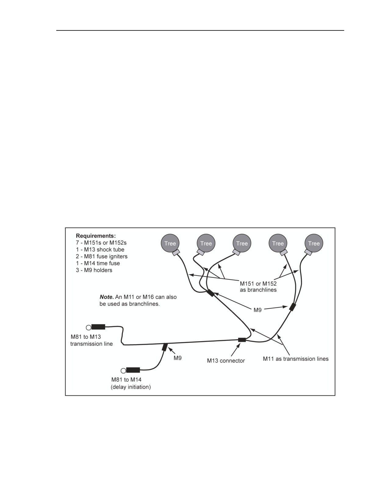
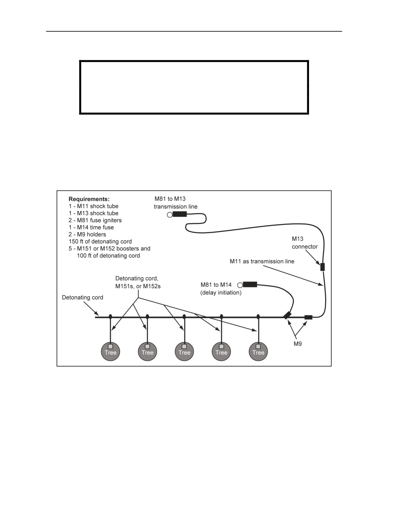
2-148. Figure 2-66 shows external timber charges using dual initiation. The following steps are used when
placing external timber charges:
Step 1. Place explosives according to the procedures outlined in Chapter 3.
Step 2. Lay out transmission lines from the charge to the firing point.
Step 3. Lay out branchlines from the charges to the holder on the M12 transmission line. Insert
the branchlines into the holder, snap the hinged flap shut, and tape it closed.
Step 4. Prime the charges according to the procedures outlined in Chapter 3, using minimal
personnel on the site.
Step 5. Inspect the firing system while moving to the firing point once all charges have been
properly placed and primed. At the firing point, attach the M81 fuse igniter to the end of the
M12 or M13 transmission line and initiate the firing system.
Figure 2-66. External Timber Charges Using Dual Initiation
11 July 2007
FM 3-34.214
2-81
Chapter 2
INTERNAL TIMBER CHARGE
WARNING
Do not use MDI shock tube components for priming internal
charges. Use the M151 or M152. Failure to comply could result in
immediate personal injury or damage to equipment.
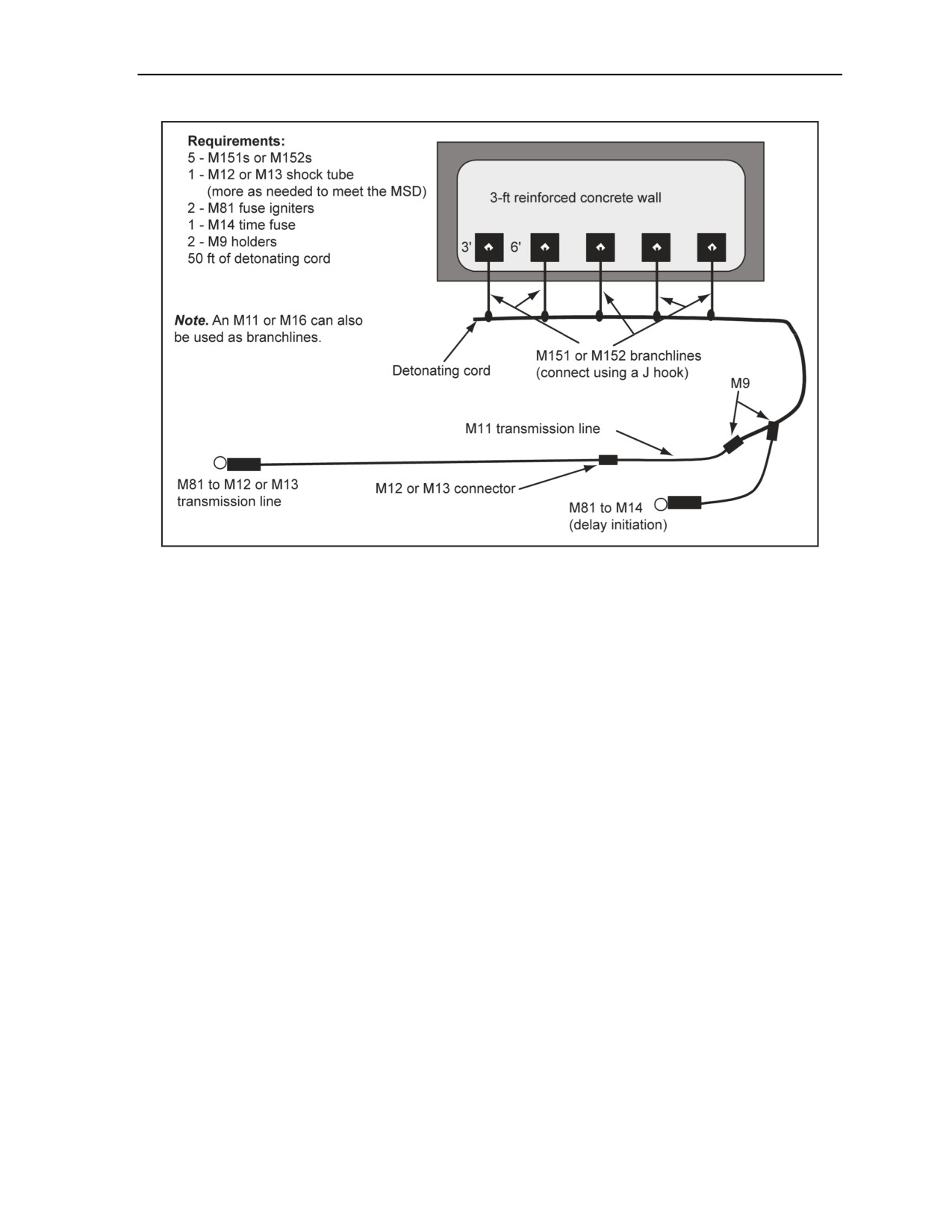
2-149. Figure 2-67 shows internal timber charges with dual initiation. The following steps are used when
placing internal timber charges:
Step 1. Place primed explosives according to the procedures outlined in Chapter 3.
Step 2. Lay out transmission lines from the charge to the firing point.
Step 3. Lay out branchlines.
Step 4. Tie the branchlines into the line main.
Step 5. Construct the line main according to the procedures outlined in Chapter 2.
Step 6. Connect the transmission line to the line main using an M9 holder, and tape it closed.
Figure 2-67. Internal Timber Charges With Dual Initiation
BREACHING CHARGES
2-150. Breaching charges are emplaced according to the procedures outlined in Chapter 3. See
Figure 2-68.
2-82
FM 3-34.214
11 July 2007
Initiating Sets, Priming Methods, Firing Systems, and Modernized Demolition Initiators
Figure 2-68. Breaching Using Detonating Cord and Dual Initiation
MINEFIELD BREACHING CHARGES
2-151. Emplace (mine or countermine) breaching charges according to the procedures outlined in FM
3-34.210. Using blasting cap components is not very efficient due to the time constraints and direct-fire
exposure. Use of M151 or M152 boosters or detonating cord are the preferred methods for minefield-
breaching charges during tactical or protective-minefield breaches.
11 July 2007
FM 3-34.214
2-83

This page is intentionally left blank.

Chapter 3
Charge Calculations and Placement
This chapter discusses charge calculations. Included are the six-step, problem-solving
formats for all types of calculations and the different methods for placing charges.
SECTION I - DEMOLITIONS
DEMOLITION PRINCIPLES
3-1. The amount and placement of explosives are key factors in military demolition projects. Formulas
are available to help an engineer calculate the required amount of explosives. Demolition principles and
critical-factor analysis guide a Soldier in working with explosive charges. The available formulas for
demolition calculations are based on the detonation effects, the charge dimension significance, and the
charge-placement significance.
DETONATION EFFECTS
3-2. When an explosive detonates, it violently changes into highly compressed gas. The explosive type,
density, confinement, and dimensions determine the rate at which the charge changes to a gaseous state.
The resulting pressure then forms a compressive shock wave that shatters and displaces objects in its path.
A HE charge detonated in direct contact with a solid object produces the following three detectable,
destructive effects:
Deformation. The shock wave charge deforms the surface of the object directly under the
charge. When the charge is placed on a concrete surface, it causes a compressive shock wave
that crumbles the concrete in the immediate vicinity of the charge, forming a crater. When
placed on a steel surface, the charge causes an indentation or depression about the size of the
charge contact area.
Spalling. The shock wave of the charge chips away at the surface of the object directly under the
charge. This action is known as spalling. If the charge is large enough, it will spall the opposite
side of the object. Because of the difference in density between the target and the air, the
compressive shock wave of the charge reflects as a tensile shock wave from the free surface if
the target has a free surface on the side opposite the charge. This action causes spalling of the
target-free surface. The crater and spalls may meet to form a hole through the wall in concrete
demolitions. On a steel plate, the charge may create one spall in the shape of the explosive
charge, throwing the spall from the plate.
Radial cracking. If the charge is large enough, the expanding gases can create a pressure load
on the object that will cause cracking and displacing of material. This effect is known as radial
cracking. When placed on concrete walls, the charge may crack the surface into a large number
of chunks and project them away from the center of the explosion. When placed on steel plates,
the charge may bend the steel away from the center of the explosion.
CHARGE DIMENSION SIGNIFICANCE
3-3. The force of an explosion depends on the quantity and power of the explosive. The destructive effect
depends on the direction of the explosive force. To transmit the greatest shock, a charge must have the
optimal relationship of the contact area and the thickness to the target volume and density. If a calculated
charge is spread too thinly, not enough space will be provided for the shock wave to reach full velocity
before striking the target. In improperly configured explosives (too thin or wrong strength), the shock wave
tends to travel in a parallel rather than a perpendicular direction to the surface. As a result, the volume of
11 July 2007
FM 3-34.214
3-1

Chapter 3
the target will be too much for the resulting shock wave. Additionally, a thick charge with too small a
contact area will transmit a shock wave over too small a target area with much lateral loss of energy.
CHARGE PLACEMENT SIGNIFICANCE
3-4. The destructive effect of an explosive charge depends on the location of the charge in relation to the
size, shape, and configuration of the target. For the most destructive effect, detonate an explosive of the
proper size and shape for the size, shape, and configuration of the target. Any significant air or water gap
between the target and explosive will lessen the force of the shock wave. Cut explosives (such as sheet or
plastic explosives) to fit odd-shaped targets. Whenever possible, place explosive charges to detonate
through the smallest part of the target. Use internal charges to achieve maximum destruction with minimum
explosives expense. Tamping external charges increases their destructive effect.
CHARGE TYPES
3-5. Internal and external charges are the two charge types. Internal charges are charges that are placed in
boreholes in the target. External charges are charges that are placed on the surface of the target.
INTERNAL CHARGES
3-6. Internal charges are confined with tightly packed sand, wet clay, or other material (stemming).
Stemming is the process of packing material on top of an internal borehole or crater charge. Stemming
material is filled and tamped against the explosive to fill the borehole to the surface. In drilled holes, tamp
the explosive as it is loaded into the hole. Stemming material should be tamped only with a nonsparking
tool.
EXTERNAL CHARGES
3-7. External charges are covered and tamped with tightly packed sand, clay, or other dense material.
Stemming material may be loose or in sandbags. To be most effective, make the thickness of the tamping
material at least equal to the breaching radius. Small breaching charges are tamped on horizontal surfaces
with several inches of wet clay or mud.
CHARGE CALCULATION FACTORS
3-8. The amount of explosives required is calculated for any demolition project. Charge calculations are
based on the following critical factors:
Type and strength of target materials. A target may be timber, steel, or other material.
Concrete may be reinforced with steel to increase the strength of the concrete.
Target size, shape, and configuration. These characteristics all influence the required type and
amount of explosives. For example, large or odd-shaped targets, such as concrete piers and steel
beams, are more economically demolished with multiple charges than with a single charge.
Desired demolition effect. The extent of the demolition project and the other desired effects
should be considered, such as the direction that trees will fall when constructing an abatis.
Explosive type. The characteristics of each explosive type determine its application for
demolition purposes. Table 1-1, pages 1-2 and 1-3, lists these characteristics.
Charge size and placement (Table 3-1). When using external charges without considering
placement techniques, use a flat, square charge with a thickness-to-width ratio of 1:3.
Charges should be fastened to the target using wire, adhesive compound, tape, or string.
Charges should be propped against targets with wooden or metal frames made of scrap or
other available materials or placed in boreholes.
Tamping method. If you do not completely seal or confine the charge or if you do not ensure
the material surrounding the explosive is balanced on all sides, the force of the explosive will
escape through the weakest spot. To keep as much explosive force as possible on the target, pack
material around the charge to fill any empty space. This material is called tamping material, and
3-2
FM 3-34.214
11 July 2007
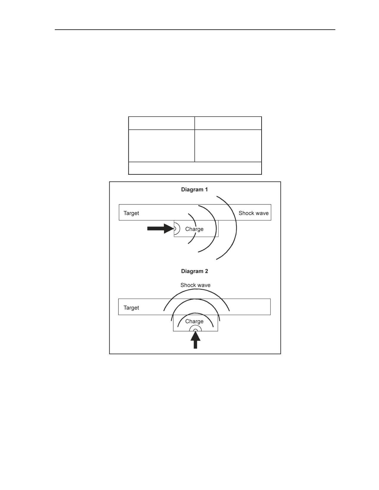
Charge Calculations and Placement
the process is called tamping. Sandbags and earth are examples of common tamping materials.
Always tamp charges with a nonsparking tool.
Priming direction. The direction in which the shock wave travels through the explosive charge
will affect the rate of energy transmitted to the target. If the shock wave travels parallel to the
surface of the target (Figure 3-1, Diagram 1), the shock wave will transmit less energy over a
period of time than if the direction of detonation is perpendicular to the target (Figure 3-1,
Diagram 2). For best results, prime the charge in the center of the face farthest from the target.
Table 3-1. Breaching Charge Thickness
Charge Weight (lb)
Charge Thickness (in)
Less than 5
1
5 to less than 40
2
40 to less than 300
4
300 or more
8
Note. If using TNT, use the approximate thickness.
Figure 3-1. Direction of Initiation
EXPLOSIVE SELECTIONS
3-9. Explosive selection for successful demolition operations is a balance between the factors listed in
paragraph 3-8 and the practical aspects; target type; the amount and types of explosives, materials (such as
sandbags), equipment, and personnel available; and the amount of time available to accomplish the
mission.
11 July 2007
FM 3-34.214
3-3

Chapter 3
CHARGE CALCULATIONS
3-10. Use the six-step, problem-solving format below for all charge calculations. This format is used to
determine the weight (P) of the explosives required for a demolition task in pounds of TNT. If using an
explosive other than TNT, adjust P accordingly by dividing P for TNT by the relative effectiveness (RE)
factor of the explosive you plan to use (Table 1-1, pages 1-2 and 1-3).
Step 1. Determine the critical dimensions of the target.
Step 2. Calculate the weight of a single charge of TNT by using the appropriate demolition
formula.
Step 3. Divide the quantity of explosive by the RE factor. Skip this step if using TNT.
Step 4. Determine the number of packages of explosive for a single charge by dividing the
individual charge weight by the standard package weight of the chosen explosive. Round this
result to the next higher, whole package. Use volumes instead of weights for special-purpose
charges (ribbon, diamond, saddle, and similar charges).
Step 5. Determine the number of charges based on the targets.
Step 6. Determine the total quantity of explosives required to destroy the target by multiplying
the number of charges (step 5) by the number of packages required per charge (step 4).
SECTION II - NORMAL CUTTING CHARGES
TIMBER-CUTTING CHARGES
3-11. Plastic explosives are the best timber-cutting charges for both internal and external placement. These
explosives make excellent internal charges because they are easily tamped into boreholes. They make
excellent external charges, because they are easy to tie, tape, or fasten to the target. Timber will vary
widely in its physical properties from location to location, requiring careful calculation. Therefore, make
test shots on the specific timber type to determine the optimal size of the timber-cutting charge.
INTERNAL CHARGES
3-12. The following formula is used to calculate internal cutting charges:
D2
2
P =
or P = 0.004D
250
where—
P
= TNT required per tree (in pounds)
D
= diameter or the least dimension of dressed timber (in inches)
Note. Diameter = circumference divided by 3.14
For trees that are up to 18 inches in diameter, use one hole to place the explosive. For larger trees, use two
holes drilled at right angles to each other without intersecting but as close together as possible. Two-inch
diameter holes should be drilled to a depth equal to two-thirds of the diameter of the tree. Evenly split the
required charge between the holes. This will allow enough room to place the explosive in the holes and
leave enough room to cap them with mud or clay (Figure 3-2). For dimensioned timber requiring two
boreholes, place the boreholes side by side. When placing the charges, form the plastic explosive to the
approximate diameter of the hole. To not reduce the density of the explosive, try to minimize the amount of
molding. The charge is primed with detonating cord (see Chapter 2, Section II) and placed in the hole. A
nonsparking tool is used to finish filling the holes by packing them with mud or clay. When using two
boreholes, connect the branchlines in a British junction
(Figure
2-33, page
2-29). For an example
calculation, see Appendix F (Figure F-1, page F-1).
3-4
FM 3-34.214
11 July 2007
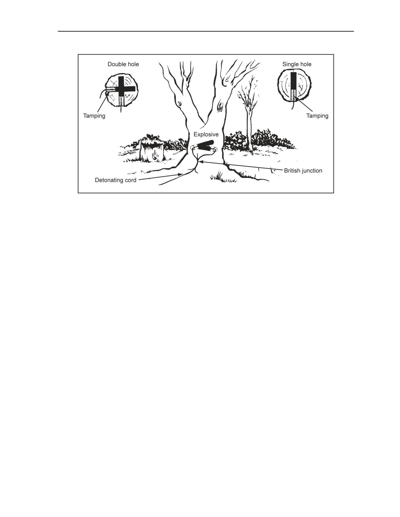
Charge Calculations and Placement
Figure 3-2. Timber-Cutting Charge (Internal)
EXTERNAL CHARGES
3-13. To be most effective, external charges should be rectangular, 1 to 2 inches thick, and twice as wide as
they are high. Remove the bark to place the explosive in direct contact with solid wood and to reduce air
gaps between the charge and the wood. If the timber is not round or if the direction of fall is not important,
place the explosive on the widest face. This will concentrate the force of the blast through the least
dimension of the timber. Trees will fall toward the side on which the explosive is placed, unless influenced
by the wind or the lean of the tree (Figure 3-3, page 3-6). If the tree is leaning the wrong way or a strong
wind is blowing, place a 1-pound kicker charge on the side opposite the main charge, about two-thirds of
the way up the tree. The kicker charge is fired at the same time as the main charge. For the best results
when using composition C4, orient the longest dimension of the charge horizontally. Orienting the charges
vertically tends to allow gaps to develop between the charges. Use the following formula to determine the
amount of explosive needed for cutting trees, posts, beams, or other timber using untamped external
charges.
For
an
example
calculation,
see
Figure F-2, page F-2.
D2
2
P = or P = 0.025D
40
where—
P
= TNT required per target ( in pounds)
D
= diameter or least dimension of dimensioned timber (in inches)
11 July 2007
FM 3-34.214
3-5
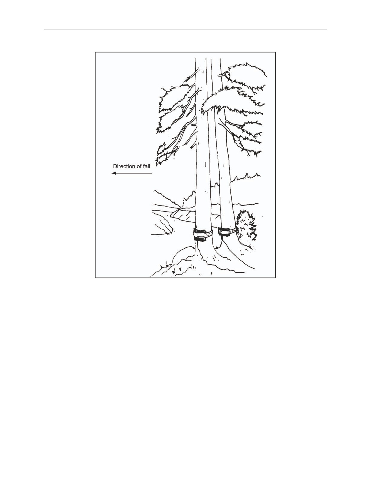
Chapter 3
Figure 3-3. Timber-Cutting Charge (External)
RING CHARGE
3-14. The ring charge is a band of explosives that completely encircles the tree (Figure 3-4). The explosive
band should be as wide as possible and at least 1/2 inch thick for small-diameter trees (up to 15 inches in
diameter) and 1 inch thick for medium- and large-diameter trees (up to 30 inches in diameter). Remove the
bark to place the explosive in direct contact with solid wood and to reduce air gaps between the charge and
the wood. Determine the amount of explosive necessary by using the external-charge formula. Prime the
ring charge in two opposing places with branchlines. Connect the branchlines in a British junction
(Figure 2-33, page 2-29).
3-6
FM 3-34.214
11 July 2007
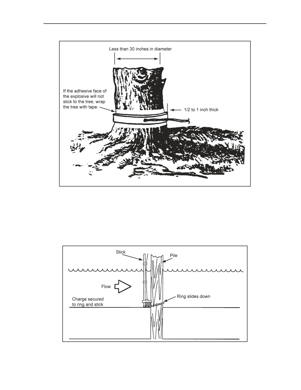
Charge Calculations and Placement
Figure 3-4. Timber-Cutting Ring Charge
UNDERWATER CHARGES
3-15. To cut a timber pile underwater, a method similar to the one shown in Figure 3-5 should be used. The
charge size is determined using the breaching formula. On the upstream side of the pile, the charge should
be placed as deep as possible. The stream flow on this part of the pile will maximize the tamping effect on
the explosive. If timber underwater is to be cut below mud or sand, engineer diver assets can be used to
water jet the soil away before charges are placed.
Figure 3-5. Cutting a Timber Pile Underwater
11 July 2007
FM 3-34.214
3-7
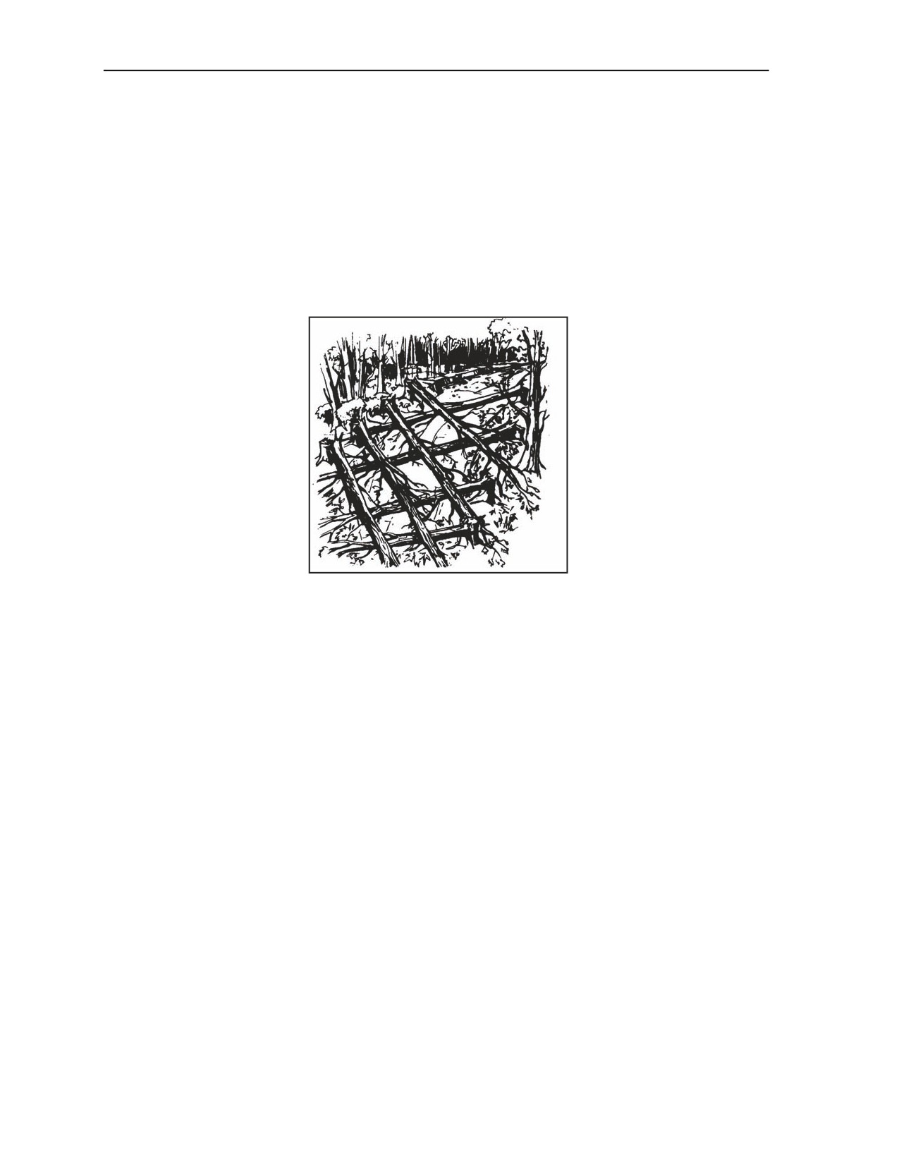
Chapter 3
ABATIS
3-16. Fallen tree obstacles (Figure 3-6) are made by cutting trees that remain attached to their stumps.
Since trees vary in their physical properties, a test shot should be conducted if time and explosives are
available. The following formula is used to compute the amount of TNT required for the test shot:
D2
2
P = or P = 0.02D
50
where—
P
= TNT required per tree (in pounds)
D
= diameter or least dimension of dimensioned timber( in inches)
Figure 3-6. Abatis
Placement
3-17. External placement should be used with the charge 5-feet aboveground level. The tree will fall
toward the side where the explosive is attached unless influenced by the lean of the tree or wind.
Special Considerations
3-18. The following should be considered when creating an abatis:
Place a 1-pound kicker charge on the side opposite the main charge, about two-thirds of the way
up the tree, if the tree is leaning the wrong way or a strong wind is blowing. Fire the kicker
charge at the same time as the main charge.
Ensure that the obstacle will cover at least 75 meters in depth.
Ensure that the individual trees are at least 2 feet in diameter. Smaller trees are not effective
obstacles against tracked vehicles.
Fell trees 3 to 5 meters apart to create a condition to prevent tracked vehicles from driving over
the top of the obstacle.
Fell the trees at a 45° angle toward the enemy.
Simultaneously detonate the charges on one side of the road at a time and then fell the trees on
the other side of the road.
Enhance the obstacle with the use of wire, mines, and booby traps.
HASTY TIMBER CALCULATIONS
3-19. The situation sometimes require the use of hasty timber calculations. Table 3-2 lists the required
number of composition C4 packages for cutting timber with internal, external, and abatis charges.
3-8
FM 3-34.214
11 July 2007
Charge Calculations and Placement
Table 3-2. Timber-Cutting Charge Size
Packages of Composition C4 (1.25-lb packages) Required by
Charge
Timber Diameter (in)
Type
6
8
10
12
15
18
21
24
27
30
33
36
Internal
1
1
1
1
1
1
2
2
2
3
3
4
External
1
1
2
3
4
5
7
9
11
14
17
20
Abatis
—
—
—
—
—
—
—
7
9
11
14
16
Note. The packages required are rounded up to the next whole package.
STEEL-CUTTING CHARGES
WARNING
Steel-cutting charges produce metal fragments. Proper
precautions should be taken to protect personnel. Failure to
comply could result in immediate personal injury or damage to
equipment.
3-20. In order to prepare steel-cutting charges, the target factors and the explosive factors must be known.
The paragraphs below discuss the target and explosive factors.
TARGET FACTORS
3-21. Target configuration and target materials are critical in steel-structure demolitions, more so than with
other materials.
Target Configuration
3-22. The configuration of the steel in the structure determines the type and amount of charge necessary for
successful demolition. Examples of structured steel are I beams, wide-flange beams, channels, angle
sections, structural Ts, and steel plates used in building or bridge construction.
Target Materials
3-23. In addition to its configuration, steel also has a varied composition. It includes—
High-carbon steel. Metalworking dies and rolls are composed of high-carbon steel and are very
dense.
Alloy steel. Gears, shafts, tools, and plowshares are usually composed of alloy steel. Chains and
cables are often made from alloy steel; however, some chains and cables are composed of high-
carbon steel. Alloy steel is not as dense as high-carbon steel.
Cast iron. Some steel components (such as railroad rails and pipes) are composed of cast iron.
Cast iron is very brittle and easily broken.
Nickel-molybdenum steel. Nickel-molybdenum steel cannot be cut easily by conventional
steel-cutting charges. The jet from a shaped charge will penetrate it, but cutting requires multiple
charges or linear-shaped charges. Nickel-molybdenum steel shafts can be cut with a diamond
charge, but not with the saddle charge. Therefore, use some method other than explosives to cut
nickel-molybdenum steel, such as thermite, acetylene, or electrical cutting tools.
11 July 2007
FM 3-34.214
3-9
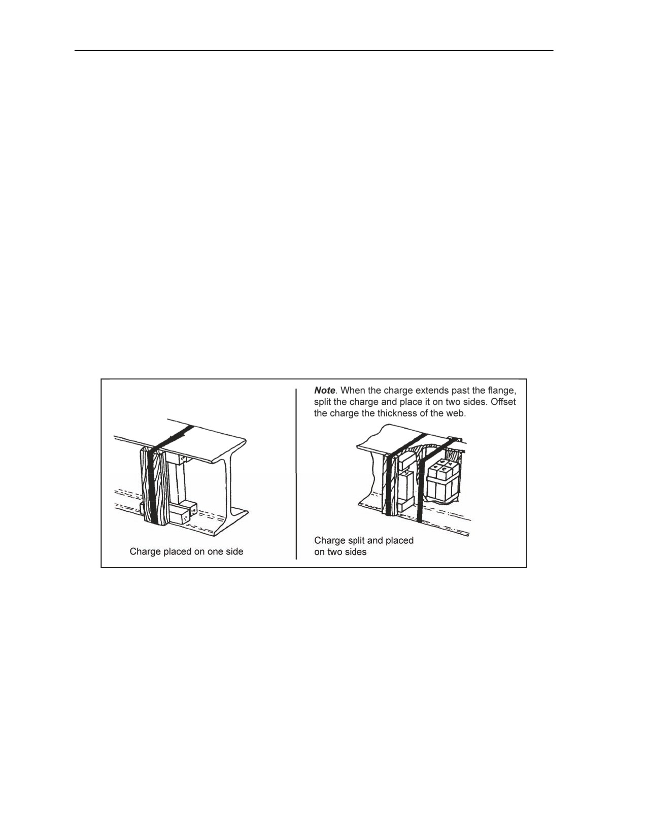
Chapter 3
EXPLOSIVE FACTORS
3-24. In steel-cutting charges, the type, placement, and size of the explosive are important. Confining or
tamping the charge is rarely practical or possible. The type, placement, and size are factors that are
important when selecting steel-cutting charges.
Type
3-25. Plastic explosive (composition C4) and sheet explosive are the best explosives for steel cutting.
These explosives have very effective cutting power and are easily cut and shaped to fit tightly into the
grooves and angles of the target. These explosives are particularly effective when demolishing structural
steel, chains, and steel cables.
Placement
3-26. See Figure 3-7. To achieve the most effective initiation and results, ensure that—
The charge is continuous over the complete line of the proposed cut.
There is close contact between the charge and the target.
The width of the cross section charge is between one and three times its thickness. Do not use
charges more than 6 inches thick, because better results can be achieved by increasing the width
rather than the thickness.
The long charges are primed every 4 to 5 feet. If butting composition C4 packages end-to-end
along the line of the cut, prime every fourth package.
The direction of initiation is perpendicular to the target (Figure 3-1, page 3-3).
Figure 3-7. Placing Charges on Steel Members
Size
3-27. The size of the charge is dictated by the type and size of the steel I beam and the charge type
selected. Either composition C4 or TNT block explosives can be used for the cutting steel; composition C4
works the best. Each steel configuration requires a unique charge size.
Block Charge
3-28. The following formula will give you the charge size necessary for cutting I beams, built-up girders,
steel plates, columns, and other structural steel sections. When calculating cutting charges for steel beams,
the area for the top flange, web, and the bottom flange should be calculated. Built-up beams have rivet
heads and angles or welds joining the flanges to the web. The thickness of one rivet head and the angle iron
must be added to the flange thickness when determining the thickness of a built-up beam flange. The
thinnest point of the web is used as the web thickness (the rivet head and angle iron thickness should be
3-10
FM 3-34.214
11 July 2007

Charge Calculations and Placement
ignored). The lattice of lattice girder webs are cut diagonally by placing a charge on each lattice along the
line of the cut. Use Table 3-3 and Table 3-4, page 3-12, to determine the correct amount of explosive
necessary for cutting steel sections. The following formula is used to determine the required charge size
(Table 3-3 is based on this formula) (see sample calculations in Appendix F, Figures F-3 and F-4, pages
F-3 and F-4):
3
P = (
) A or P = 0.375A
8
where—
P
= TNT required (in pounds)
A
= cross-sectional area of the steel member (in square inches) cross-sectional area for a circular
target (A = π r2 [π = 3.14])
Table 3-3. Hasty, Steel-Cutting Chart for TNT
Average
Pounds of Explosive (TNT) for Rectangular Steel Sections of Given Dimensions
Thickness
of Section
Height of Section (in)
(in)
2
3
4
5
6
7
8
9
10
11
12
14
16
18
20
22
24
1/4
0.2
0.3
0.4
0.5
0.6
0.7
0.8
0.9
1.0
1.1
1.2
1.3
1.5
1.7
1.9
2.1
2.3
3/8
0.3
0.5
0.6
0.7
0.9
1.1
1.2
1.3
1.4
1.6
1.7
2.0
2.3
2.6
2.8
3.1
3.4
1/2
0.4
0.6
0.8
1.0
1.2
1.4
1.5
1.7
1.9
2.1
2.3
2.7
3.0
3.4
3.8
4.2
4.5
5/8
0.5
0.7
1.0
1.2
1.4
1.7
1.9
2.2
2.4
2.7
2.9
3.3
3.8
4.3
4.7
5.2
5.7
3/4
0.6
0.9
1.2
1.4
1.7
2.0
2.3
2.6
2.8
3.1
3.4
4.0
4.5
5.1
5.7
6.3
6.8
7/8
0.7
1.0
1.4
1.7
2.0
2.4
2.7
3.0
3.3
3.7
4.0
4.6
5.3
6.0
6.6
7.3
7.9
1
0.8
1.2
1.5
1.9
2.3
2.7
3.0
3.4
3.8
4.2
4.5
5.3
6.0
6.8
7.5
8.3
9.0
11 July 2007
FM 3-34.214
3-11

Chapter 3
Table 3-4. Hasty, Steel-Cutting Chart for Composition C4
Follow these steps to use this table:
1. Measure each rectangular section of the total member separately.
2. Find the appropriate charge size for the rectangular section from the table. Use the next larger dimension if the
section dimension is not listed in the table.
3. Add the individual charges for each section to obtain the total charge weight.
Weight of Composition C4 Required for Rectangular Steel Sections
Section
(height or width, in inches)
Thickness (in)
2
3
4
5
6
8
10
12
14
16
18
20
22
24
1/4
0.2
0.3
0.3
0.4
0.5
0.6
0.8
0.9
1.0
1.2
1.3
1.5
1.6
1.8
3/8
0.3
0.4
0.5
0.6
0.7
0.9
1.1
1.3
1.5
1.8
2.0
2.1
2.4
2.6
1/2
0.3
0.5
0.6
0.8
0.9
1.2
1.5
1.8
2.1
2.3
2.6
2.9
3.2
3.4
5/8
0.4
0.6
0.8
0.9
1.1
1.5
1.8
2.2
2.5
2.9
3.2
3.5
3.9
4.3
3/4
0.5
0.7
0.9
1.1
1.3
1.8
2.1
2.6
3.0
3.4
3.8
4.3
4.7
5.1
7/8
0.6
0.8
1.1
1.3
1.5
2.1
2.5
3.0
3.5
4.0
4.5
5.0
5.5
5.9
1
0.6
0.9
1.2
1.5
1.8
2.3
2.9
3.4
4.0
4.5
5.1
5.6
6.2
6.8
Note. Round up to the nearest 1/10 pound when calculating charge size.
High-Carbon or Alloy Steel
3-29. The following formula should be used to determine the required charge for cutting high-carbon or
alloy steel:
P = D2
where—
P
= TNT required (in pounds)
D
= diameter or thickness of section to be cut (in inches)
Steel Bars, Rods, Chains, and Cables (Up to 2 Inches)
3-30. The size of these materials make proper charge placement difficult. For example, Figure 3-8 shows a
charge placement on a chain. If the explosive is long enough to bridge both sides of the link or is large
enough to fit snugly between the two links, use one block. If the explosive is not large enough to bridge
both sides, two blocks should be used. The following amount of explosive should be used:
One pound of explosive for materials up to and including 1 inch in diameter or thickness.
Two pounds of explosive for materials between 1 and 2 inches in diameter or thickness. Prime
both charges so they will detonate simultaneously.
Note. Experience has shown that a link filled with explosive will be severed by detonation. See
Appendix G for the underwater method.
3-12
FM 3-34.214
11 July 2007
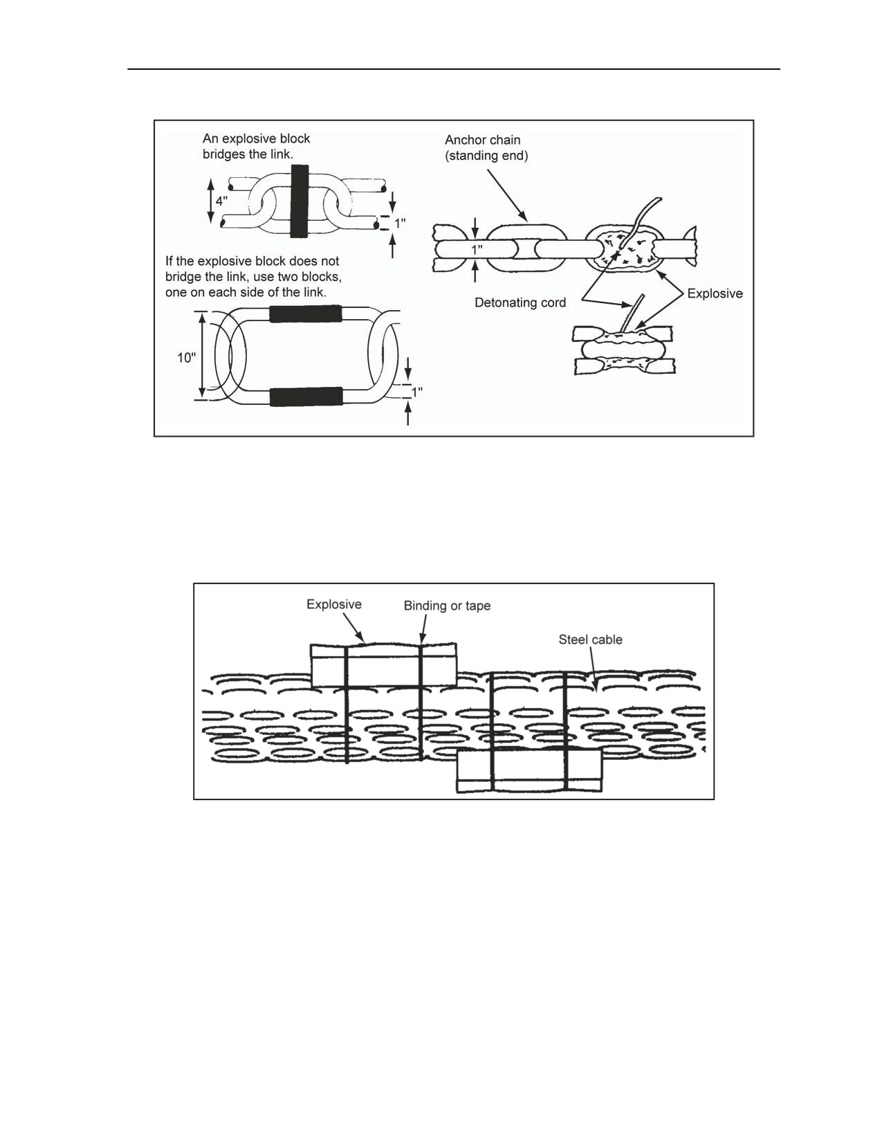
Charge Calculations and Placement
Figure 3-8. Charge Placement on Chains
Steel Bars, Rods, Chains, and Cables (Over 2 Inches)
3-31. When the target diameter or thickness is 2 inches or greater, the equation for high-carbon or alloy
steel should be used. When the thickness or diameter is 3 inches or greater, half of the charge should be
placed on each side of the target, and the placement should be staggered to produce the maximum-shearing
effect (Figure 3-9).
Figure 3-9. Charge Placement on a Steel Cable (3 Inches or Larger)
Railroad Rails
3-32. The height of the railroad rail is the critical dimension for determining the amount of explosives
required. For rails 5 inches or more in height, such as rail crossovers or switches, 1 pound of explosives
should be used. For rails less than 5 inches high, use 1/2 pound of explosives (Figure 3-10, page 3-14).
Railroad frogs require 2 pounds of explosives. If possible, charges should be placed at vulnerable points,
such as frogs, switches, and crossovers. Charges should be placed at alternate rail splices for a distance of
500 feet and on the inside of the rails.
11 July 2007
FM 3-34.214
3-13
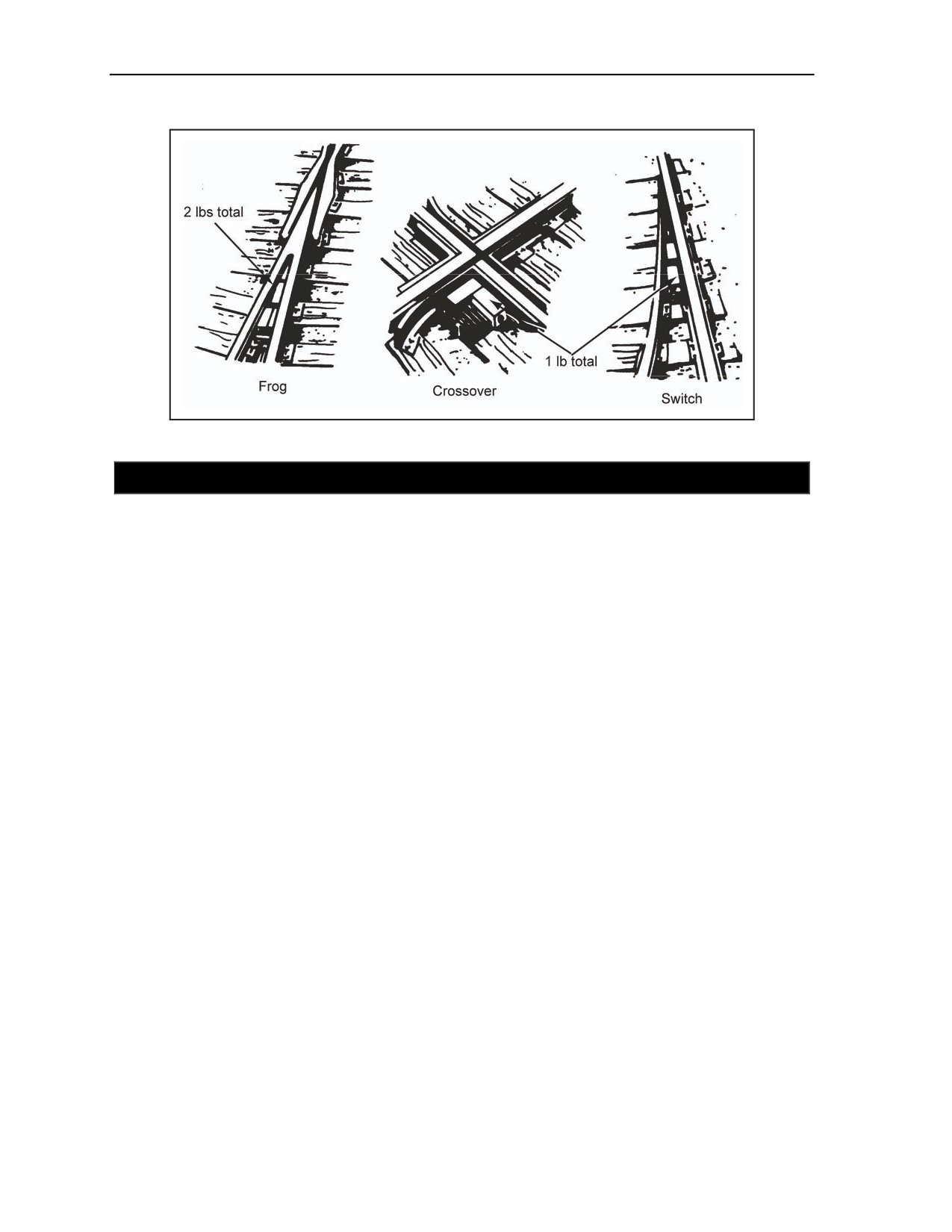
Chapter 3
Figure 3-10. Charge Placement on Railroad Rails
SECTION III - SPECIAL CUTTING CHARGES
PURPOSE
3-33. When time and circumstances permit, special cutting charges (ribbon, saddle, and diamond charges)
should be used instead of conventional cutting charges. These charges may require extra time to prepare,
since they require exact and careful target measurement to achieve optimal effect. With practice, an
engineer can become proficient at calculating, preparing, and placing these charges in less time than
required for traditional charges. Special cutting charges use considerably less explosive than conventional
charges. Plastic-explosive (M112) or sheet explosive (M186) charges should be used as special charges.
Composition C4 requires considerable cutting, shaping, and molding that may reduce its density and,
therefore, its effectiveness. Using special cutting charges requires considerable training and practice.
RIBBON CHARGE
3-34. Ribbon charges are used to cut flat, steel targets up to 3 inches thick (Figure 3-11). The charge
thickness is made one-half the target thickness, but never less than 1/2 inch. The charge width is made three
times the charge thickness and the length of the charge is equal to the length of the desired cut. Ribbon
charges are detonated from the center of the C-shaped charge and the center of the top and bottom flange
charges when placing on I beams or wide-flange beams. When using the ribbon charge to cut structural
steel sections, the charge should be placed as shown in Figure 3-12. The detonating cord branchlines must
be the same length and must connect in a British junction (Figure 2-33, page 2-29). Figure F-5, page F-5,
shows how to calculate steel-cutting charges for steel plates. The charge thickness, width, and length is
determined as follows:
Charge thickness. The charge thickness equals one-half the thickness of the target; however, it
will never be less than 1/2 inch. The thickest part of the target is used to calculate the charge
thickness.
Charge width. The charge width equals three times the charge thickness.
Charge length. The charge length equals the length of the desired cut.
3-14
FM 3-34.214
11 July 2007
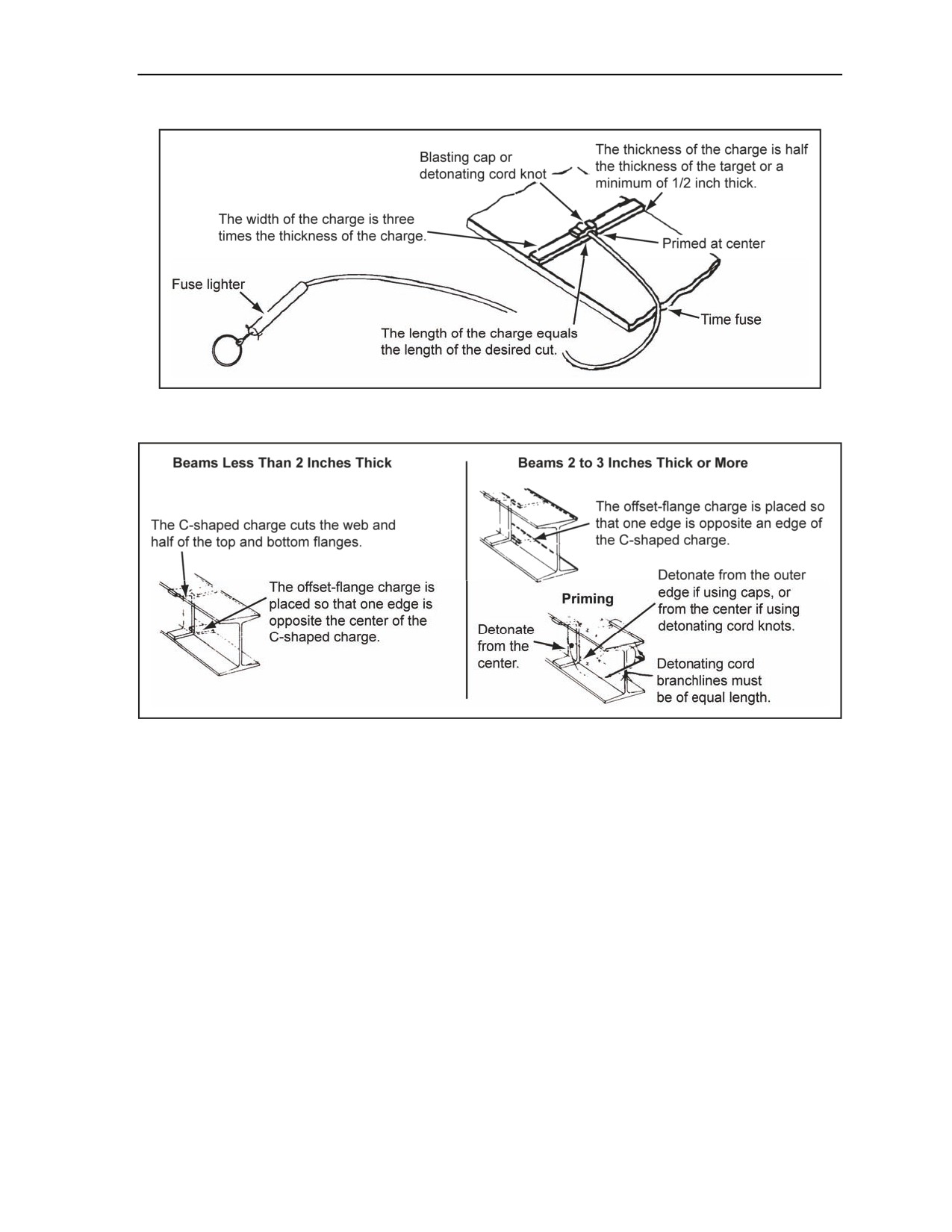
Charge Calculations and Placement
Figure 3-11. Using a Ribbon Charge
Figure 3-12. Placing a Ribbon Charge on Structural Steel
SADDLE CHARGE
3-35. This steel cutting method uses the destructive effect of the cross fracture formed in the steel by the
base of the saddle charge (the end opposite the point of initiation). This charge is used on mild steel bars,
whether round, square, or rectangular shaped, up to 8 inches in diameter (Figure 3-13, page 3-16). The
charge is made 1 inch thick. The dimensions, detonation, and the placement of the saddle charge is
determined as follows (see Figure F-7, page F-7, for an example calculation on steel cutting charges for
steel bars):
Dimensions.
Thickness. The charge should be made 1 inch thick (the standard thickness of M112 block
explosive).
Base width. The base width should be made equal to one-half the target circumference or
perimeter.
Long-axis length. The long-axis length should be made equal to the target circumference
or perimeter.
Volume (cubic inches). The volume is computed as: Long axis x base x 0.5 = volume.
Detonation. Detonate the saddle charge by placing a blasting cap or detonating cord knot at the
apex of the long axis.
11 July 2007
FM 3-34.214
3-15
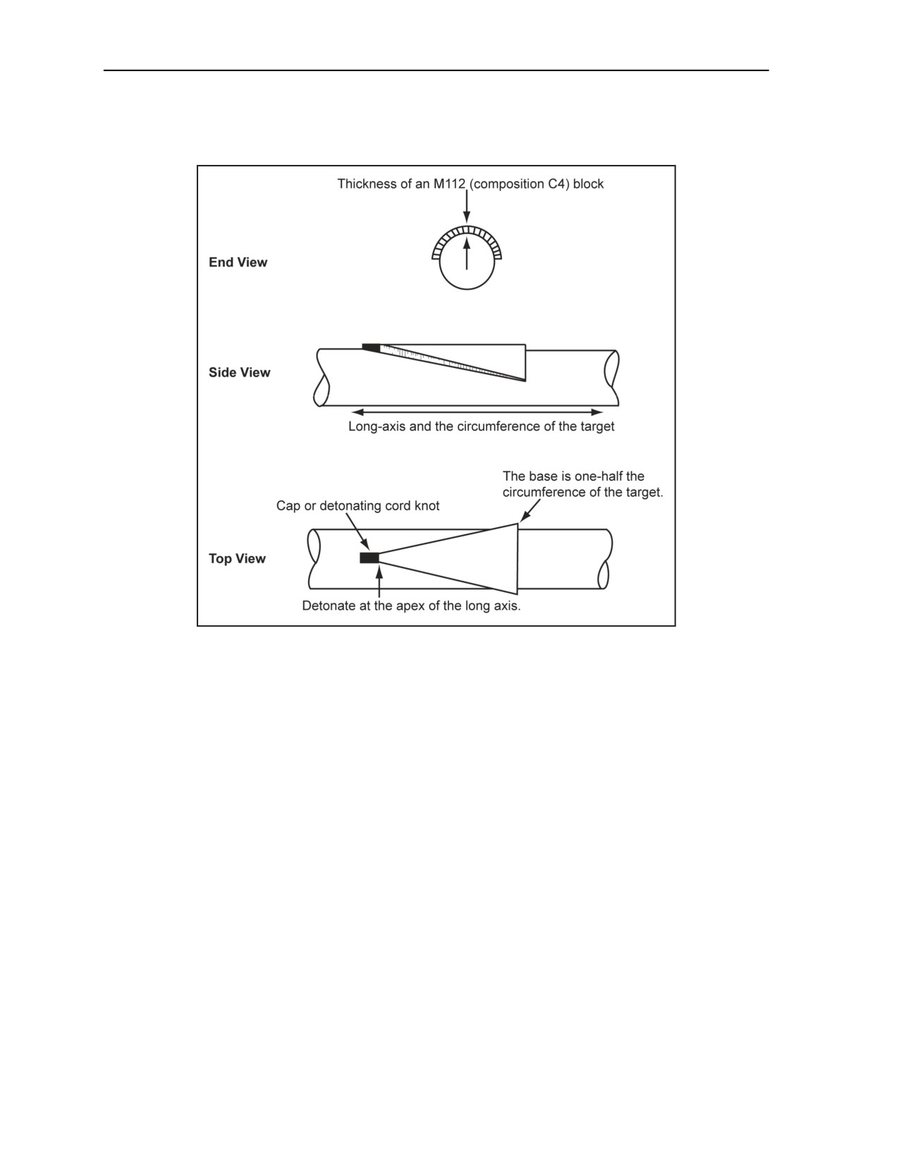
Chapter 3
Placement. Ensure that the long axis of the saddle charge is parallel with the long axis of the
target. Cut the charge to the correct shape and dimensions, and then place it around the target.
Ensure that the charge maintains close contact with the target by taping the charge to the target.
Figure 3-13. Using a Saddle Charge
DIAMOND CHARGE
3-36. This stress-wave method employs the destructive effect of two colliding shock waves. The
simultaneous detonation of the charge from opposite ends (Figure 3-14) produces the shock waves. The
diamond charge is used on high-carbon or alloy steel bars that are up to 8 inches in diameter. The
dimensions, placement, and priming are determined as follows (for an example calculation on steel-cutting
charges for high-carbon steel, see Figure F-8, page F-7:
Dimensions.
Thickness. The charge should be made 1 inch thick (the standard thickness of an M112
block explosive).
Long-axis length. The long-axis length should be made equal to the target circumference.
Short-axis length. The short-axis length should be made equal to one-half the long axis.
Volume (cubic inches). The volume is computed as: Long axis x short axis x 0.5 = volume.
Placement. Place the explosive completely around the target so that the ends of the long axes
touch. Slightly increase the charge dimensions to do this, if necessary. Tape the charge to the
target to ensure adequate contact with the target.
Priming. Prime the diamond charge (Figure 3-14) with two detonating cord branchlines using
one of the following methods:
Detonating cord knots (Figure 2-15, page 2-15).
Two caps.
3-16
FM 3-34.214
11 July 2007
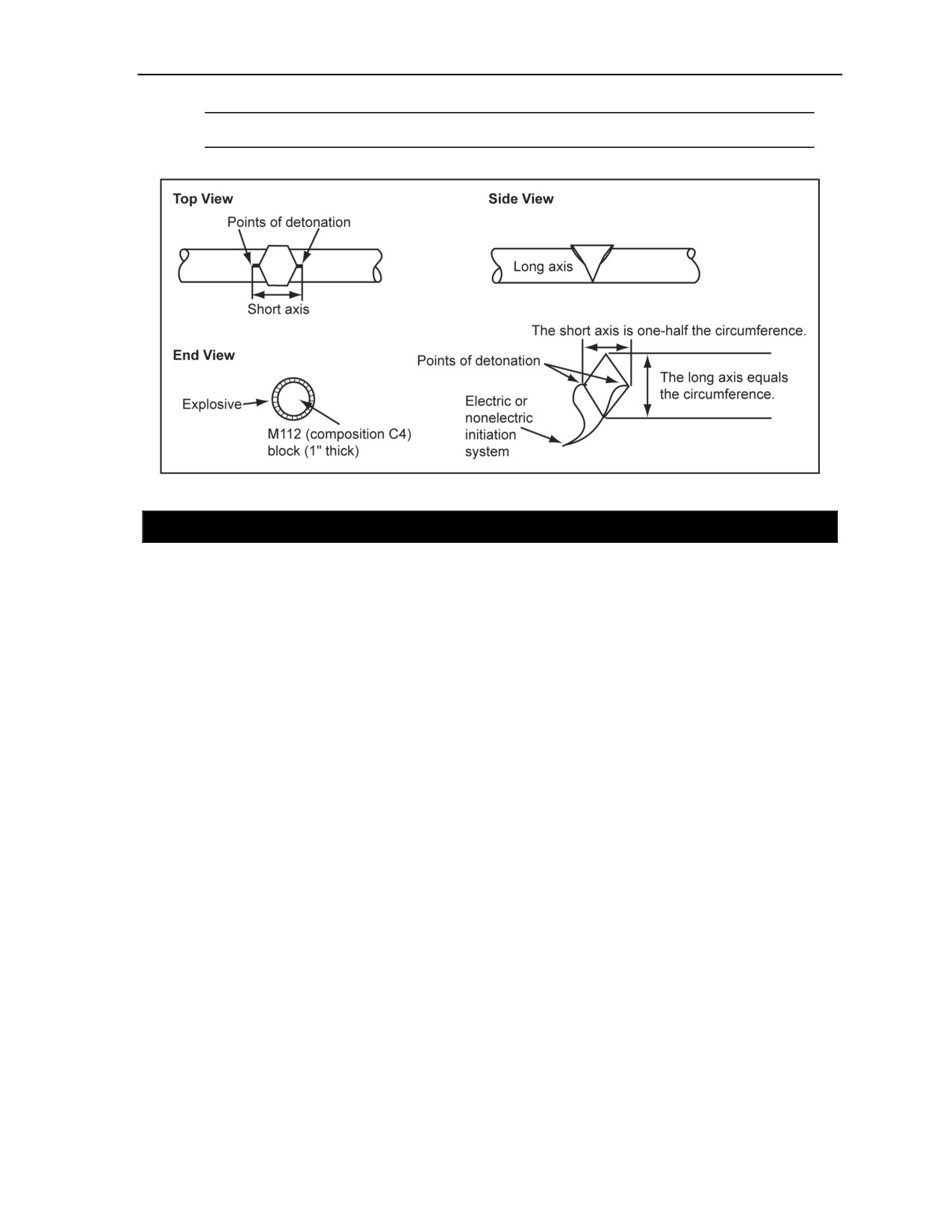
Charge Calculations and Placement
Note. When using a British junction, ensure that the branchlines are the same length.
Figure 3-14. Using a Diamond Charge
SECTION IV - BREACHING CHARGES
CRITICAL FACTORS
3-37. Breaching charges are used to destroy bridge piers, bridge abutments, and permanent field
fortifications. The size, shape, placement, and tamping or confinement of breaching charges is critical to
success. The size and confinement of the explosive are the most critical factors, because the targets are
usually very strong and bulky. The intent of breaching charges is to produce and transmit enough energy to
the target to make a crater and create spalling. Breaching charges placed against reinforced concrete will
not cut metal reinforcing bars. After the concrete is breached, remove or cut the reinforcement with a steel-
cutting charge.
COMPUTATION
3-38. When performing a computation for breaching charges, the formula to determine the size of the
charge must be known. The breaching radius, the material factor, and the tamping factor must also be
known.
FORMULA
3-39. The following formula is used to determine the size of the charge required to breach concrete,
masonry, rock, or similar material:
P = R3KC
where—
P
= TNT required (in pounds)
R
= breaching radius( in feet)
K
= material factor, which reflects the strength, hardness, and mass of the material to be demolished
(Table 3-5, page 3-18)
C
= tamping factor, which depends on the location and tamping of the charge (Figure 3-15, page
3-18).
11 July 2007
FM 3-34.214
3-17
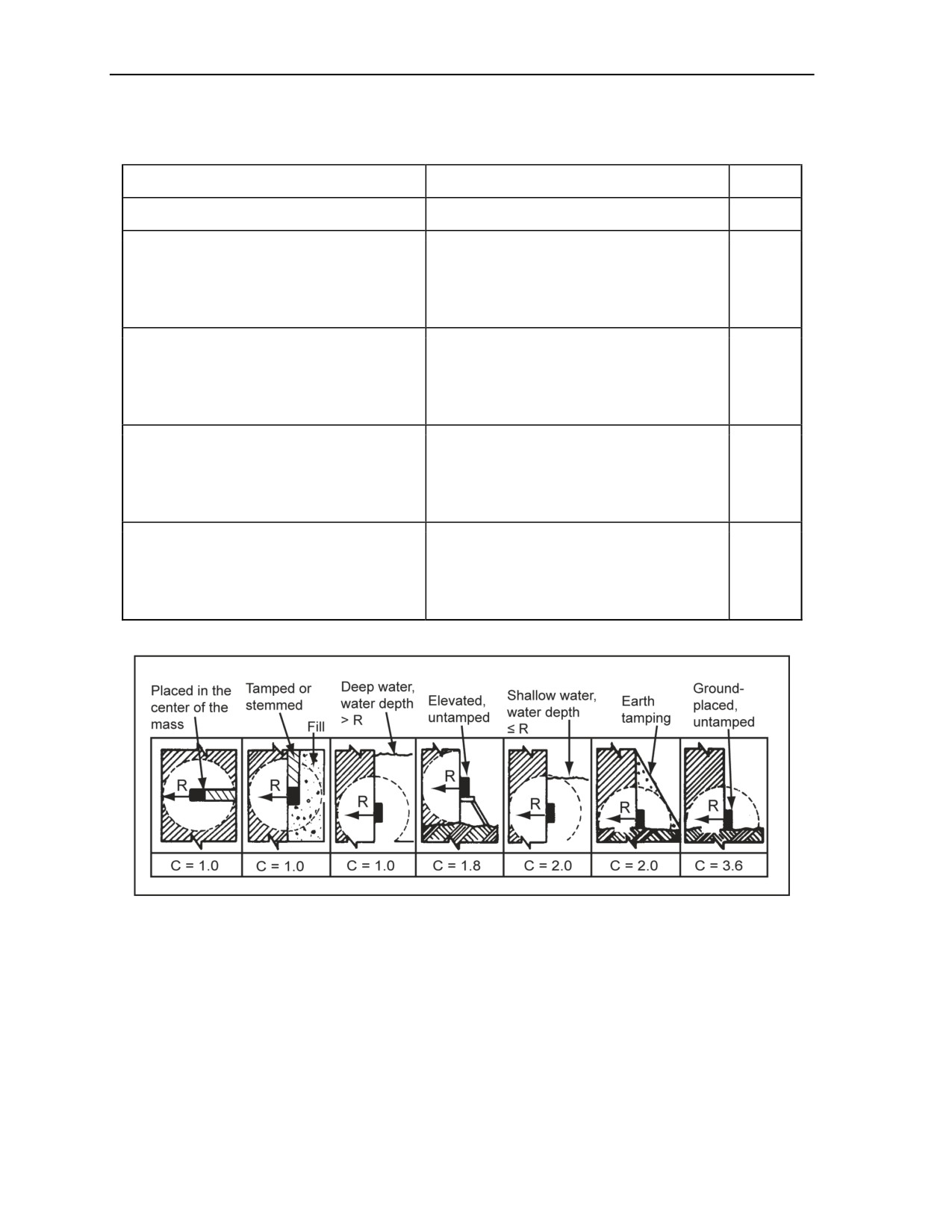
Chapter 3
Table 3-5. Material Factor (K) for Breaching Charges
Material
R
K
Earth
All values
0.07
Poor masonry
Less than 1.5 m (5 ft)
0.32
Shale
1.5 m (5 ft) or more
0.29
Hardpan
Good timber
Earth construction
0.3 m (1 ft) or less
0.88
Good masonry,
Over 0.3 m (1 ft) to less than 0.9 m (3 ft)
0.48
Concrete block
0.9 m (3 ft) to less than 1.5 m (5 ft)
0.40
Rock
1.5 m (5 ft) to less than 2.1 m (7 ft)
0.32
2.1 m (7 ft) or more
0.27
0.3 m (1 ft) or less
1.14
Over 0.3 m (1 ft) to less than 0.9 m (3 ft)
0.62
Dense concrete
0.9 m (3 ft) to less than 1.5 m (5 ft)
0.52
First-class masonry
1.5 m (5 ft) to less than 2.1 m (7 ft)
0.41
2.1 m (7 ft) or more
0.35
0.3 m (1 ft) or less
1.76
Over 0.3 m (1 ft) to less than 0.9 m (3 ft)
0.96
Reinforced concrete (factor does not consider
0.9 m (3 ft) to less than 1.5 m (5 ft)
0.80
cutting steel)
1.5 m (5 ft) to less than 2.1 m (7 ft)
0.63
2.1 m (7 ft) or more
0.54
Figure 3-15. Tamping Factor (C) for Breaching Charges
BREACHING RADIUS
3-40. The breaching radius for external charges is equal to the thickness of the target being breached. For
internal charges placed in the center of the target mass, the breaching radius is one-half the thickness of the
target. If the charge is placed at less than one-half the mass thickness, the breaching radius is the longer of
the distances from the center of the charge to the outside surfaces of the target. For example, when
breaching a 4-foot wall with an internal charge placed 1 foot into the wall, the breaching radius is 3 feet
(the longest distance from the center of the explosive to an outside target surface). If placed at the center of
the wall mass, the breaching radius of the explosive is 2 feet (one-half the thickness of the target). The
3-18
FM 3-34.214
11 July 2007

Charge Calculations and Placement
breaching radius is 4 feet for an external charge on this wall. Values of R are rounded to the next higher
1/4-foot distance for internal charges and to the next higher 1/2-foot distance for external charges.
MATERIAL FACTOR
3-41. The material factor represents the strength and hardness of the target material. Table 3-5 gives values
for K for various types and thicknesses of material. When the target material cannot be positively
identified, assume that the target consists of the strongest material type in the general group. Always
assume that concrete is reinforced and masonry is first-class unless the exact condition and construction of
the target materials is known.
TAMPING FACTOR
3-42. The tamping factor depends on the charge location and the tamping materials used. Figure 3-15
shows the methods for placing charges and gives the values of C for both tamped and untamped charges.
When selecting a value for C from Figure 3-15, do not consider a charge tamped with a solid material (such
as sand or earth) as fully tamped unless the charge is covered to a depth equal to or greater than the
breaching radius. The water depth must be greater than the radius to use 1 as C.
REINFORCED CONCRETE BREACHING
3-43. Table
3-6, page
3-20, gives the number of composition C4 packages required for breaching
reinforced concrete targets. The breaching-charge formula does not factor in cutting the steel. The
remaining steel is cut using steel-cutting charges. The amounts of composition C4 in the table are based on
the formula in paragraph 3-39, page 3-17. To use the table, do the following:
Measure the concrete thickness.
Decide how the charge will be placed against the target. Compare the method of placement with
the diagrams at the top of Table 3-6. Use the column that lists the greatest amount of explosive if
in doubt about which column to use.
Select the amount of explosive required based on the target thickness, using the column directly
under the chosen placement method. For example, 200 packages of composition C4 are required
to breach a 7-foot, reinforced concrete wall with an untamped charge placed 7-feet aboveground.
Note. See Figure F-9, page F-8, for an example calculation on breaching charges for a
reinforced-concrete pier.
MATERIALS BREACHING
3-44. Table 3-6 can be used to determine the amount of composition C4 required for other materials by
multiplying the value from the table by the proper conversion factor from Table 3-7, page 3-21. The
following procedure can be used:
Determine the material type in the target. Assume that the material is the strongest type from the
same category if in doubt.
Determine from Table 3-6 the amount of explosive required if the object is made of reinforced
concrete.
Find the appropriate conversion factor from Table 3-7.
Multiply the number of packages of explosive required (Table 3-6) by the conversion factor
(Table 3-7).
11 July 2007
FM 3-34.214
3-19
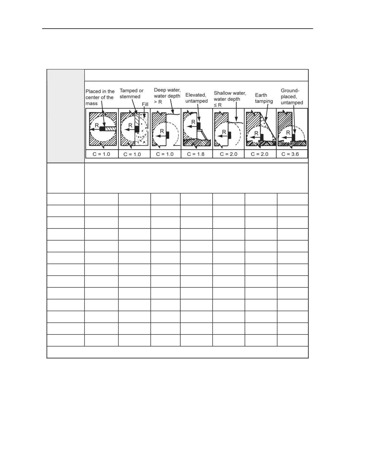
Chapter 3
Table 3-6. Breaching Charges for Reinforced Concrete
Placement Methods
Reinforced
Concrete
Packages of M112 (Composition C4)
Thickness
(ft)
2.0
1
5
5
9
10
10
17
2.5
2
9
9
17
18
18
33
3.0
2
13
13
24
26
26
47
3.5
4
21
21
37
41
41
74
4.0
5
31
31
56
62
62
111
4.5
7
44
44
79
88
88
157
5.0
9
48
48
85
95
95
170
5.5
12
63
63
113
126
126
226
6.0
13
82
82
147
163
163
293
6.5
17
104
104
186
207
207
372
7.0
21
111
111
200
222
222
399
7.5
26
137
137
245
273
273
490
8.0
31
166
166
298
331
331
595
Note. The results of all calculations for this table have been rounded up to the next whole package.
3-20
FM 3-34.214
11 July 2007

Charge Calculations and Placement
Table 3-7. Conversion Factors for Material Other Than Reinforced Concrete
Material
Conversion Factor
Earth
0.1
Ordinary masonry
Hardpan
Shale
Ordinary concrete
0.5
Rock
Good timber
Earth construction
Dense concrete
0.7
First-class masonry
NUMBER AND PLACEMENT OF CHARGES
3-45. When preparing breaching charges, the number and placement of the charges must be known. The
paragraphs below discuss how to determine the necessary information needed.
NUMBER OF CHARGES
3-46. The following formula is used for determining the number of charges required for demolishing piers,
slabs, or walls:
W
N =
2R
where—
N
= number of charges (If N is less than 1.25, use one charge; if N is 1.25 but less than 2.5, use two
charges; if N is equal to or greater than 2.5, round to the nearest whole number and use that many
charges.)
W = pier, slab, or wall width (in feet)
R
= breaching radius (in feet)
PLACEMENT OF CHARGE
3-47. Before a charge is placed, the limitations and configuration of the charge must be known. The
paragraphs below describe the limitations and configuration of the charge placement.
Limitations
3-48. Piers and walls offer limited locations for placing explosives. Unless a demolition chamber (space
intentionally provided in a structure for the emplacement of explosive charges) (JP 1-02) is available, place
the charges against one face of the target. Placing a charge aboveground level is more effective than
placing one directly on the ground. When the demolition requires several charges to destroy a pier, slab, or
wall and elevated charges are to be used, the charges should be distributed equally no less than one
breaching radius high from the base of the target. This takes maximum advantage of the shock wave. If
possible, place breaching charges so that there is a free reflection surface on the opposite side of the target.
This free reflection surface allows spalling to occur. If time permits, tamp all charges thoroughly with soil
or filled sandbags. The tamped area must be equal to or greater than the breaching radius. For piers, slabs,
or walls partially submerged in water, charges should be placed at a distance equal to the breaching radius
and below the waterline (Figure 3-15, page 3-18).
11 July 2007
FM 3-34.214
3-21
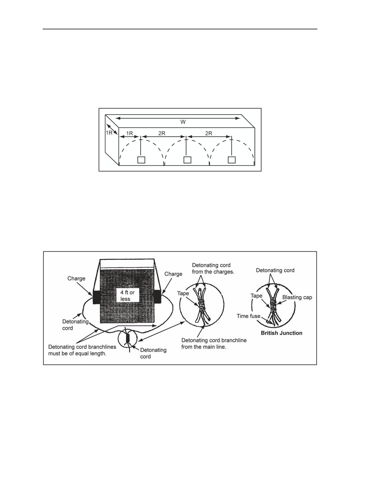
Chapter 3
Configuration
3-49. For maximum effectiveness, place the explosive charge in the shape of a flat square. The thickness of
the charge depends on the amount of explosive required (Table 3-1, page 3-3).
Placement
3-50. The first charge is placed R distance in from one side of the target. The remaining charges are spaced
at a distance of 2R apart, center to center (Figure 3-16).
Figure 3-16. Charge Placement
COUNTERFORCE CHARGES
3-51. This special breaching technique is effective against rectangular masonry or concrete columns 4 feet
thick or less. It is not effective against walls, piers, or long obstacles. The obstacle must have at least three
free faces or be freestanding. If constructed of plastic explosives (composition C4), properly placed and
detonated, counterforce charges produce excellent results with a relatively small amount of explosive. Their
effectiveness results from the simultaneous detonation of two charges placed directly opposite each other
and as near the center of the target as possible (Figure 3-17).
Figure 3-17. Counterforce Charge
CALCULATION
3-52. The thickness or diameter of the target determines the amount of plastic explosive required. The
amount of plastic explosive equals 1 1/2 times the thickness of the target in feet (1 1/2 pounds of explosive
per foot). Round fractional measurements to the next higher half foot before multiplying. For example, a
concrete target measuring 3 feet 9 inches thick requires 6 pounds of plastic explosive (1 1/2 pounds per foot
times 4 feet). For an example calculation on counterforce charges, see Figure F-10, page F-8.
3-22
FM 3-34.214
11 July 2007

Charge Calculations and Placement
PLACEMENT
3-53. When placing a counterforce charge, split the charge in half. The two halves are placed directly
opposite each other on the target. This method requires accessibility to both sides of the target so that the
charges will fit flush against their respective target sides.
PRIMING
3-54. On the face farthest from the target, prime a counterforce charge. The ends of the detonating cord
branchlines are joined in a British junction (Figure 3-17, page 3-23). The length of the branchlines must be
equal to ensure simultaneous detonation.
SECTION V - CRATERING AND DITCHING CHARGES
FACTORS
3-55. To be effective obstacles, craters must be too wide for track vehicles to span and too deep and steep-
sided for any vehicle to pass through. Blasted craters will not stop modern tanks indefinitely. A tank,
making repeated attempts to traverse a crater, will pull soil loose from the slopes of the crater, filling the
bottom, and reducing both the depth and slope angle of the crater.
SIZES
3-56. Craters are effective antitank (AT) obstacles if a tank requires four or more passes to traverse the
crater, thereby providing enough time for AT weapons to stop the tank. Craters should be large enough to
tie into natural or constructed obstacles at each end. The effectiveness of blasted craters can be improved
by placing log hurdles on either side, digging the face of the hurdle vertically on the friendly side, mining
the site with AT and antipersonnel (AP) mines, filling the crater with water, or using other means to further
delay enemy armor. Craters should be cut across the desired gap at a 45° angle from the direction of
approach. To obtain this 45° angle, the following formula should be used:
width x 1.414 = length of crater
3-57. To achieve enough obstacle depth, place craters in multiple rows. To enhance some other obstacle,
such as a bridge demolition, single or multiple rows should be used. When creating more than one row of
craters, they should be spaced far enough apart so that a single armored-vehicle-launched bridge (AVLB)
will not span them.
EXPLOSIVES
3-58. All military explosives can create AT craters. When available, use a 40-pound, composition H6,
cratering charge (Figure 1-4, page 1-8) for blasting craters.
CHARGE CONFINEMENT
3-59. Cratering charges or explosives should be placed in boreholes. Then, tamp them.
HARD-SURFACED PAVEMENT BREACHING
3-60. Hard-surfaced pavements are breached so that holes can be dug for the cratering charges. This can be
done by exploding tamped charges on the pavement surface. A 1-pound charge of explosive is used for
each 2 inches of pavement thickness. Charges are tamped twice as thick as the pavement thickness. Shaped
charges are effective for breaching hard-surfaced pavements. A shaped charge will readily blast a small-
diameter borehole through the pavement and into the subgrade. Blasting the boreholes with shaped charges
will speed up the cratering task by eliminating the need to breach the pavement with explosive charges.
After blasting, a hole should be dug for the cratering charge. Do not breach concrete at an expansion joint
because the concrete will shatter irregularly. Table 1-3, pages 1-11 and 1-12, lists hole depths and the
optimum standoff distances when using 15- or 40-pound shaped charges against various types of material.
11 July 2007
FM 3-34.214
3-23
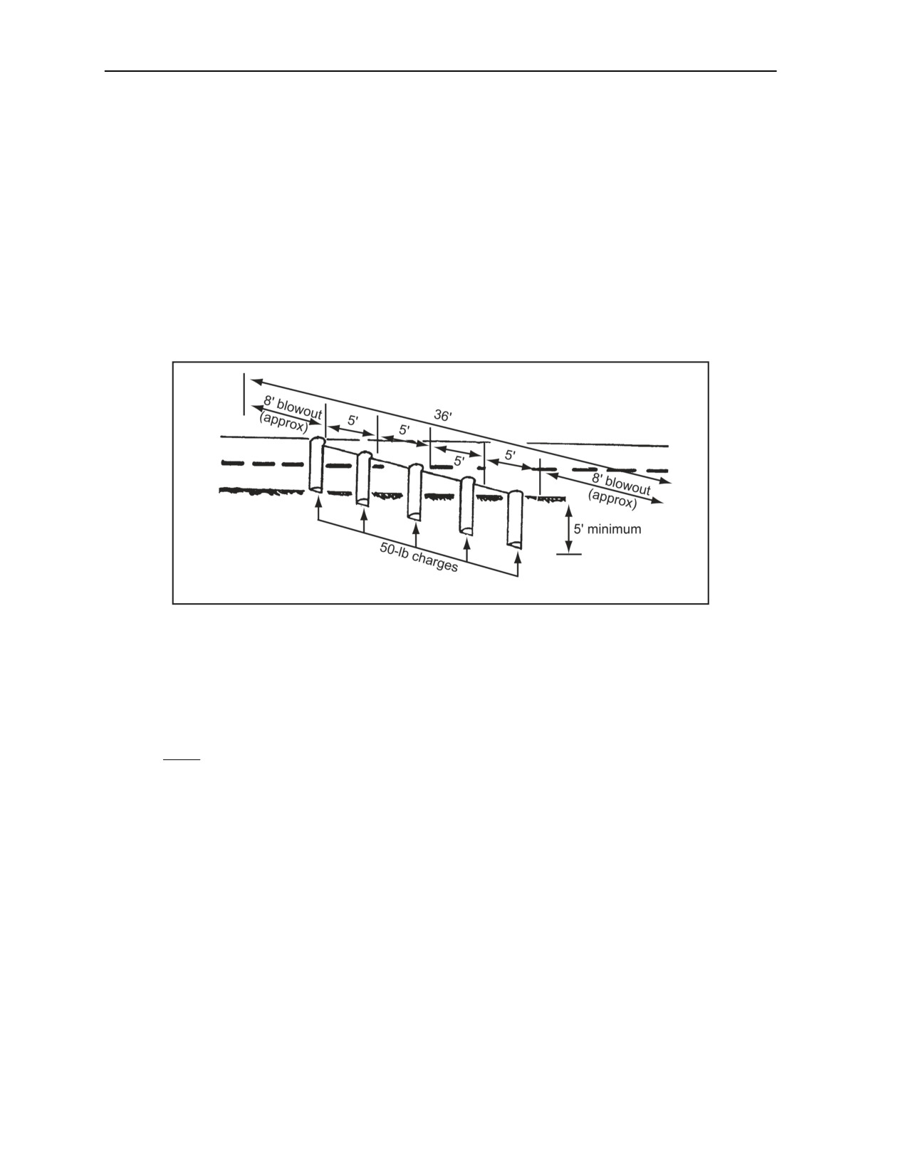
Chapter 3
Shaped charges do not always produce open boreholes capable of accepting a 7-inch diameter cratering
charge. To accommodate the cratering charge, some earth may need to be removed or narrow areas
widened. Widen deep, narrow boreholes by knocking material from the constricted areas with a pole or rod
or by breaking off the shattered concrete on the surface with a pick or crowbar and posthole diggers.
HASTY CRATER METHOD
3-61. The hasty crater method takes the least amount of time to construct, based on the number and depth
of the boreholes. However, it produces the least effective barrier because of its depth and shape
(Figure 3-18). The hasty crater method forms a V-shaped crater about 6 to 7 feet deep and 20 to 25 feet
wide, extending about 8 feet beyond each end borehole. The sides of the crater slope should be 25° to 35°.
Modern U.S. tanks require an average of four attempts to breach a hasty crater. To form a crater that is
effective against tanks, boreholes must be at least 5 feet deep with at least 50 pounds of explosive in each
hole.
Figure 3-18. Hasty Crater Charge Placement
BOREHOLES
3-62. All boreholes are to be dug the same depth (5 feet or deeper is recommended). The boreholes are
spaced at 5-foot intervals, center to center, across the area to be cratered. The following formula is used in
the six-step, problem-solving format (Section I), to compute the number of boreholes:
L - 16
N =
+ 1
5
where—
N
= number of boreholes (Round fractional numbers to the next higher, whole number.)
L
= length of the crater (in feet) (Measure across the area to be cut. Round fractional measurements to
the next higher foot.)
16
= combined blowout of 8 feet on each side
5
=
5-foot spacing
1
=
factor to convert from spaces to holes
CHARGE SIZE
3-63. Boreholes are loaded with 10 pounds of explosive per foot of borehole depth. When using standard
cratering charges, supplement each charge with additional explosives to obtain the required amount. For
example, a 6-foot hole would require one 40-pound cratering charge and 20 pounds of TNT or 16 packages
of composition C4.
3-24
FM 3-34.214
11 July 2007
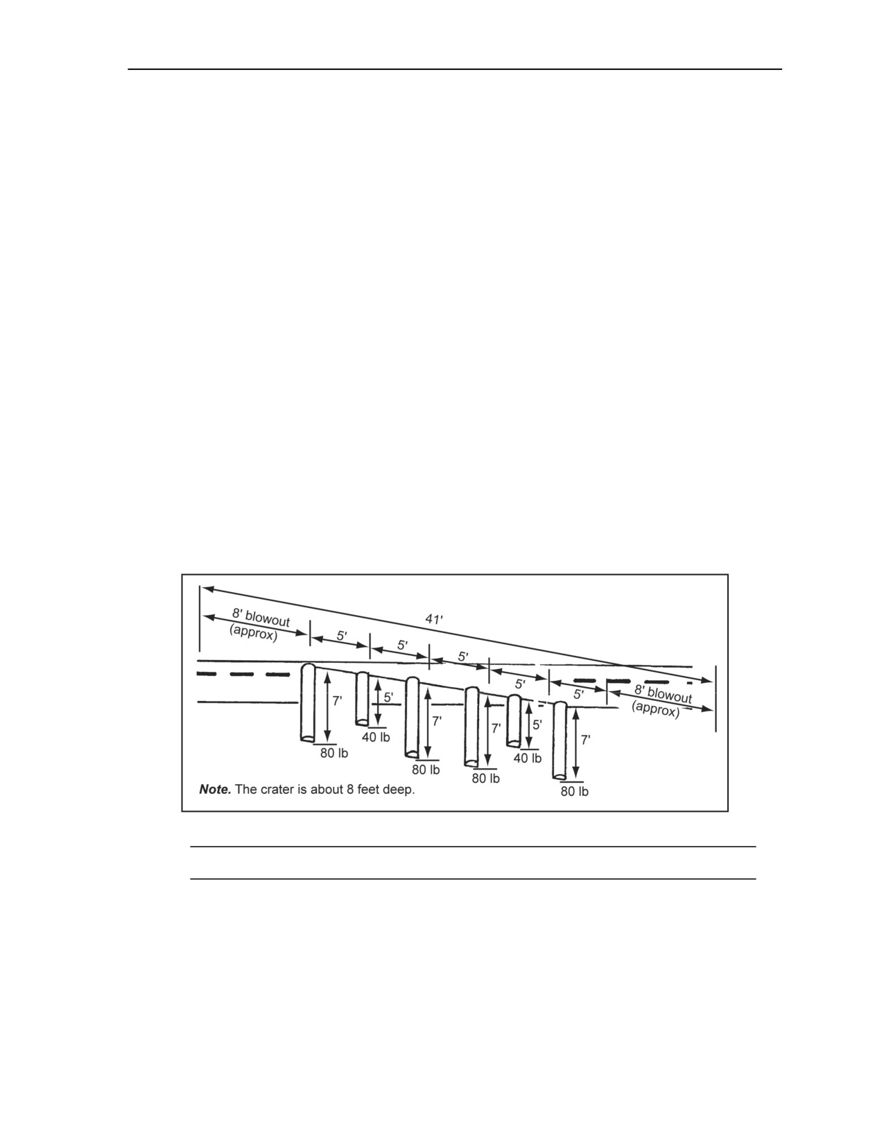
Charge Calculations and Placement
FIRING SYSTEM
3-64. Dual-firing systems should be used (Figure 2-26, page 2-25). They are initiated with an M12, M13,
or M14. The 40-pound cratering charge is dual-primed as shown in Figure 2-21, page 2-20.
BOREHOLE TAMPING
3-65. All boreholes should be tamped with suitable materials.
DELIBERATE CRATER METHOD
3-66. Figure 3-19 shows the deliberate crater method. This method produces a more effective crater than
the hasty method. Modern U.S. tanks require an average of eight attempts to breach a deliberate crater.
Placing charges deliberately produces a V-shaped crater about 7 to 8 feet deep and 25 to 30 feet wide with
side slopes of 30° to 37°. The crater extends about 8 feet beyond the end boreholes. The following steps are
used to create a deliberate crater:
Step 1. Determine the number of boreholes required, using the same formula as for a hasty
crater. Place two adjacent 7-foot boreholes in the middle when there is an even number of holes
(Figure 3-19).
Step 2. Dig or blast the boreholes 5 feet apart, center to center, in a line across the area to be cut.
Make the end boreholes 7 feet deep and the other boreholes alternately 5 and 7 feet deep. Never
place two 5-foot holes next to each other.
Step 3. Place 80 pounds of explosives in the 7-foot holes and 40 pounds of explosives in the 5
foot holes.
Step 4. Use dual-firing systems (Figure 2-26). Dual-prime the 40-pound cratering charge as
shown in Figure 2-21.
Step 5. Tamp all charges with suitable materials.
Figure 3-19. Deliberate Crater Charge Placement
Note. For an example calculation on cratering charges, see Figure F-11, page F-9.
RELIEVED-FACE CRATER METHOD
3-67. The method shown in Figure 3-20, page 3-26, produces a crater that is a more effective obstacle to
modern tanks than the hasty crater. This technique produces a trapezoidal-shaped crater about 7 to 8 feet
deep and 25 to 30 feet wide with unequal side slopes. In compact soil, such as clay, the relieved-face
cratering method will create an obstacle such as the one shown in Figure 3-20. The side nearest the enemy
slopes about 25° from the surface to the crater bottom. The opposite (friendly) side slopes about 30° to 40°
11 July 2007
FM 3-34.214
3-25
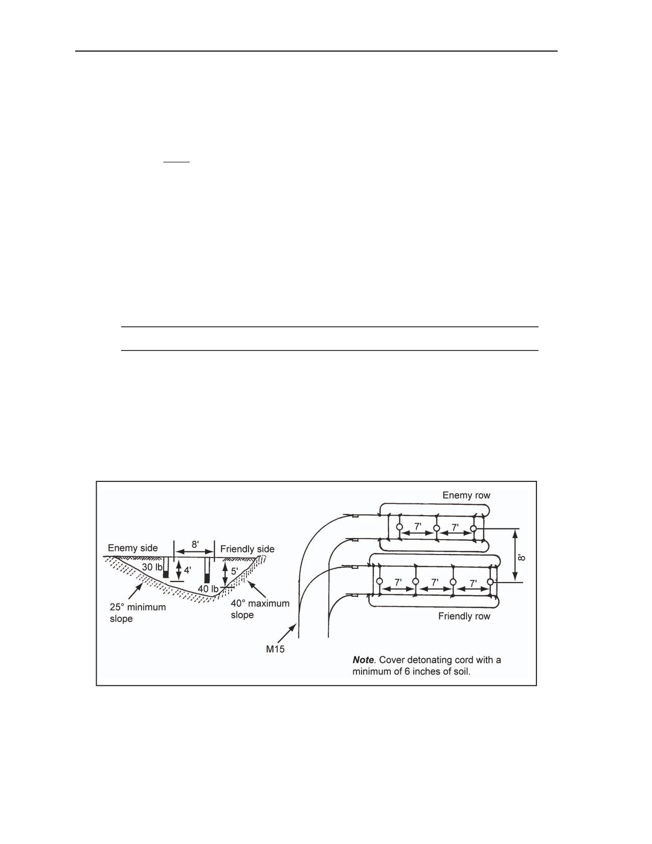
Chapter 3
from the surface to the crater bottom. However, the exact shape of the crater depends on the soil type. The
following procedures are used to create a relieved-face crater:
Drill two lines of boreholes 8 feet apart, spacing them at 7-foot centers on dirt- or gravel-
surfaced roads. Drill the two lines of boreholes 12 feet apart on hard-surfaced roads. Use the
following formula to compute the number of boreholes for the friendly-side row:
L - 10
N =
+ 1
7
where—
N
= number of boreholes (Round fractional numbers to the next higher, whole number.)
L
= crater length (in feet) (Measure across the area to be cut. Round fractional
measurements to the next higher foot.)
10
= combined blowout of 5 feet on each side
7
= spacing of holes
1
= factor to convert spaces to holes
Stagger the boreholes in the row on the enemy side in relation to the holes in the row on the
friendly side (Figure 3-20).
Note. The line closest to the enemy will always contain one less borehole than the friendly line.
Make the boreholes on the friendly side 5 feet deep, and load them with 40 pounds of explosive.
Make the boreholes on the enemy side 4 feet deep, and load them with 30 pounds of explosive.
Use a dual-firing system for each line of boreholes. Prime 40-pound cratering charges as shown
in Figure 2-21, page 2-20.
Tamp all holes with suitable material.
3-68. There must be a 0.5- to 1.5-second delay in detonation between the two rows of boreholes. An M15
may be used as the delay detonation system. On the enemy side first, detonate the row. Then fire the
friendly-side row while the earth from the enemy-side detonation is still in the air.
Figure 3-20. Relieved-Face Crater on Dirt- or Gravel-Surfaced Roads
3-26
FM 3-34.214
11 July 2007

Charge Calculations and Placement
MISFIRE PREVENTION
3-69. The shock and blast of the first row of charges may affect the delayed detonation of the friendly-side
charges. To aid in preventing misfires of the friendly-side charges, protect the detonating cord lines by
covering them with about 6 inches of earth.
CRATERS CREATED IN PERMAFROST AND ICE
3-70. Permafrost and ice can be as hard as solid rock. Therefore, procedures must be adapted for blasting
or cratering to accommodate permafrost and ice conditions.
BLASTING IN PERMAFROST
3-71. In permafrost, blasting requires about twice as many boreholes and larger charges than for cratering
operations in moderate climates. Blasted frozen soil breaks into clods 12 to 18 inches thick and 6 to
8 inches in diameter. Because normal charges have insufficient force to blow these clods clear of the
boreholes, the spall falls back into the crater when the blast subsides.
Boreholes
3-72. Before conducting extensive blasting, the soil should be tested in the area to determine the number of
boreholes needed. Boreholes are dug with standard drilling equipment, steam-point drilling equipment, or
shaped charges. Standard drilling equipment has one serious defect—the air holes in the drill bit freezes.
There is no known method to prevent this freezing. Steam-point drilling is effective for drilling boreholes
in sand, silt, or clay but not in gravel. Immediately after withdrawing the steam point, the charges should be
placed. If you do not, the area around the borehole thaws and collapses. Shaped charges are also effective
for producing boreholes, especially when forming craters. Table 1-3, pages 1-11 and 1-12, lists borehole
sizes made by shaped charges in permafrost and ice.
Explosives
3-73. If available, low-velocity explosives should be used for blasting holes in arctic climates. The
displacing quality of low-velocity explosives will more effectively clear large boulders from the crater. If
only high-velocity explosives are available, tamp the charges with water and let them freeze before
detonating. Unless thoroughly tamped, high-velocity explosives tend to blow out of the boreholes.
BLASTING IN ICE
3-74. Access holes in ice are required for obtaining water and determining the capacity of the ice for
bearing aircraft and vehicles and integrating obstacles. To accommodate rapid forward movements, ice
capacities must be determined quickly. Blasting operations provide this ability.
Boreholes
3-75. Small-diameter access holes should be made using shaped charges. An M2A4 charge will penetrate
ice as thick as 7 feet, an M3A1 charge will penetrate over 12 feet of ice (Table 1-3), and an M3A1 can
penetrate deeper. This has only been tested on ice that is about 12 feet thick. If placed at the normal
standoff distance, the charges form a large crater at the surface and require considerable probing to find an
actual borehole. A standoff distance of 42 inches or more should be used with an M2A4 shaped charge to
avoid excessive crater formation. An M2A4 creates a borehole with an average diameter of 3 1/2 inches.
An M3A1 borehole has an average diameter of 6 inches. In late winter, ice grows weaker and changes color
from blue to white. Although the structure and strength of ice vary, the crater effect is similar, regardless of
the standoff distance.
Craters
3-76. Surface craters are made with composition H6 cratering charges. For the best results, the charges
should be placed on the surface of cleared ice and tamp them with snow. When determining charge size,
11 July 2007
FM 3-34.214
3-27
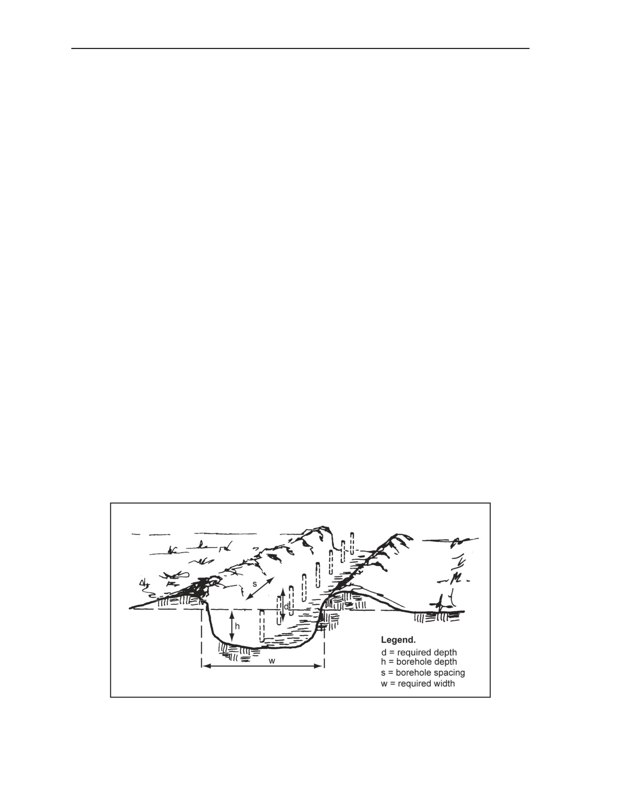
Chapter 3
keep in mind that ice has a tendency to shatter more readily than soil, and this tendency will decrease the
size of the charge.
MAKING VEHICLE OBSTACLES
3-77. A vehicle obstacle can be created in ice by first making two or more rows of boreholes. The
boreholes are spaced 9 feet apart and staggered in relation to the holes in the other rows. M112 charges are
suspended about 2 feet below the bottom surface of the ice with cords tied to sticks, bridging the sticks over
the top of the holes. The size of the charge depends on the thickness and condition of the ice. Test shots are
used to find the optimum amount. This obstacle type can retard or halt enemy vehicles for about 24 hours at
temperatures near -4°F.
CRATERS CREATED FROM CULVERTS
3-78. Destroying a culvert less than 15 feet deep may also produce an effective crater. The charges are
primed for simultaneous detonation, and sandbags are used to tamp all charges thoroughly. Culverts that
are no deeper than 5 feet are destroyed by placing explosive charges the same as for hasty road craters.
Boreholes are spaced at 5-foot intervals in the fill above and alongside the culvert. Ten pounds of
explosives per foot of depth is placed in each hole.
CRATERS CREATED FROM ANTITANK DITCHES
3-79. AT ditches are excavated by either the hasty or deliberate cratering method. Refer to the information
on hasty and deliberate cratering in this section.
DITCHING METHODS
3-80. Explosives can create ditches rapidly. Ditches are sloped at a rate of 2 to 4 feet of depth per 100 feet
of run. Ditches are placed in areas where natural erosion will aid in producing the correct grade. If a ditch
cannot be placed in an area aided by erosion, the ditch should be made deeper, increasing the depth as the
length increases. The single-line and cross-section methods are used for creating ditches.
SINGLE-LINE METHOD
3-81. The single-line method (Figure 3-21) is the most common ditching method. A single row of charges
are detonated along the centerline of the proposed ditch, leaving any further widening for subsequent lines
of charges. Table 3-8 gives charge configurations for the single-line method.
Figure 3-21. Single-Line Ditching Method
3-28
FM 3-34.214
11 July 2007
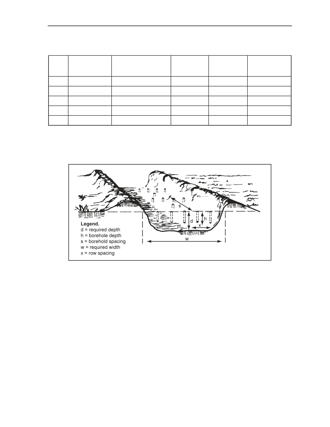
Charge Calculations and Placement
Table 3-8. Single-Line Ditching Explosives Data
Borehole
Borehole
Required Ditch
Required Width Top of
Charges per
Serial
Depth (h)
Spacing (s)
Depth (d)
Ditch (w) (in ft)
Hole (in lb)
(in ft)
(in ft)
1
2.5
5.0
0.5
1.5
1.5
2
3.0
7.0
1.0
2.0
2.0
3
4.0
9.0
2.0
3.0
3.0
4
6.0
12.0
5.0
5.0
4.0
5
10.0
16.0
10.0
8.0
5.0
CROSS-SECTION METHOD
3-82. When the full width of the ditch in one operation must be blasted, the cross-section method should be
used (Figure 3-22). Table 3-9, page 3-30, gives charge configurations for the cross-section method. An
extra charge is placed midway between the lines of charges.
Figure 3-22. Cross-Section Ditching Method
11 July 2007
FM 3-34.214
3-29
Chapter 3
Table 3-9. Cross-Section Ditching Explosives Data
Required Width (w) (ft)
Row
Charge
Borehole
Borehole
Required
Number of Boreholes in Each Cross
Spacing
Serial
per Hole
Depth (h)
Spacing
Depth (d)
Section
(x)
(in lb)
(in ft)
(s) (in ft)
(in ft)
3
5
7
9
11
1
2.5
7.5
11
13
16
18
0.5
1.5
1.3
2.5
2
3.0
10.0
13
16
19
22
1.0
2.0
1.5
3.0
3
4.0
14.0
19
24
29
34
2.0
3.0
2.5
4.5
4
6.0
20.0
28
36
44
52
5.0
5.0
4.0
6.0
5
10.0
26.0
33
46
56
65
10.0
7.0
5.0
8.0
SECTION VI - LAND-CLEARING CHARGES
STUMP REMOVAL
3-83. Stumps have two general root types—taproot and lateral root (Figure 3-23). The stump diameter is
measured 12- to 18-inches aboveground level. Then the diameter is rounded to the next higher 1/2 foot.
One pound of explosive is used per foot of diameter for dead stumps and 2 pounds of explosive per foot of
diameter for live stumps. If the complete tree is being removed, 3 pounds of explosives per foot of diameter
should be used. If the root type cannot be identified, it is assumed that the tree has a lateral-root structure
and removal proceeds accordingly.
TAPROOTED STUMPS
3-84. Two methods are common for removing taprooted stumps. One method is to drill a hole in the
taproot and place the charge in the hole. Another method is to place charges on both sides of the taproot,
creating a shearing effect (Figure 3-23). If possible, the charges should be placed in contact with the root
and at a depth about equal to the diameter of the stump.
LATERAL-ROOTED STUMPS
3-85. When blasting lateral-rooted stumps, drill sloping holes between the roots (Figure 3-23). At a depth
equal to the radius of the stump base, drill the holes Place the charges as close to the center of the stump as
possible. Trees with large lateral roots may require additional charges. Additional charges are placed
directly underneath the large lateral roots.
3-30
FM 3-34.214
11 July 2007
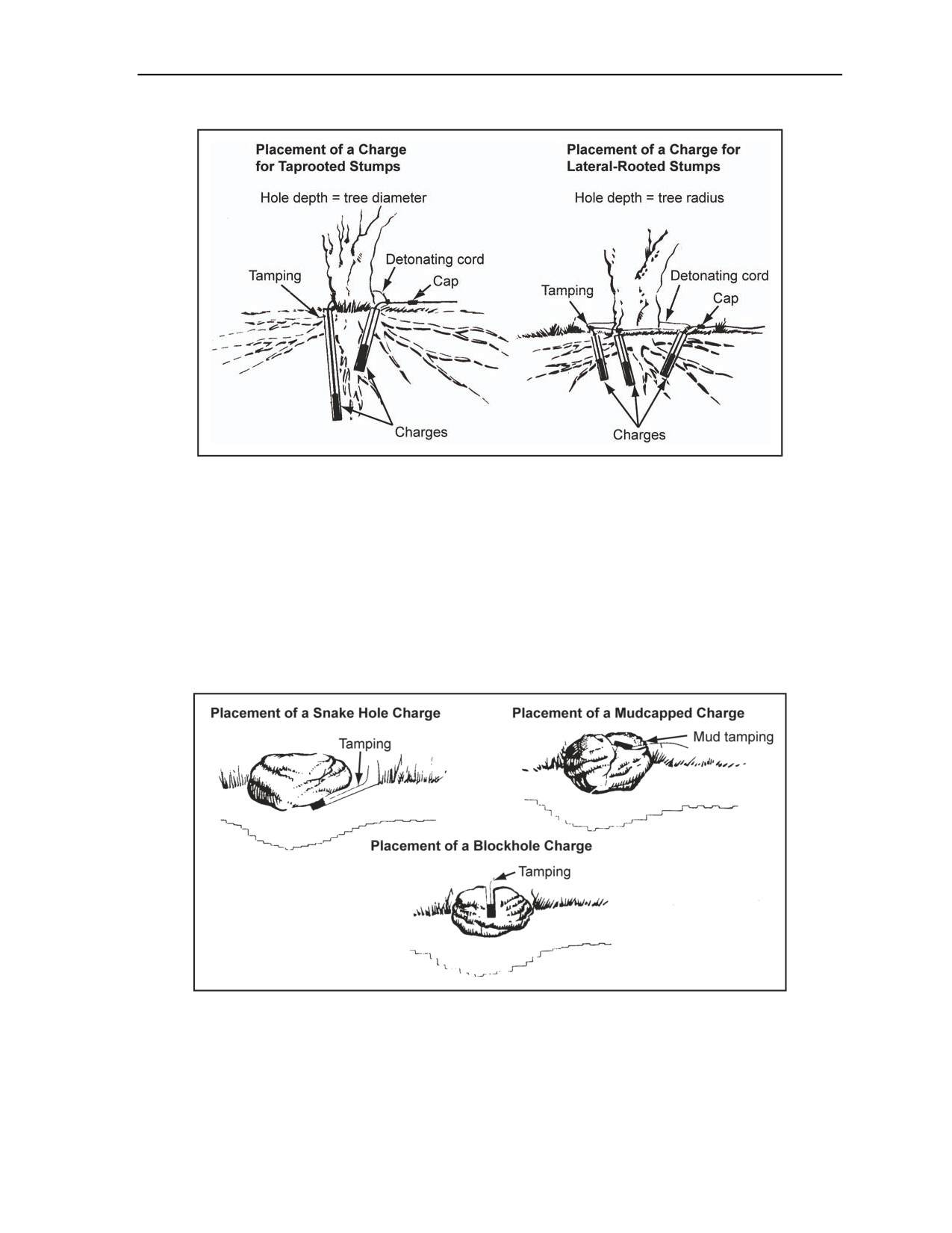
Charge Calculations and Placement
Figure 3-23. Stump Blasting
BOULDER REMOVAL
3-86. Blasting is an effective way to remove boulders. The most practical methods are snake hole, mudcap,
and blockhole.
SNAKE HOLE METHOD
3-87. This method involves digging a hole beneath the boulder large enough to hold the charge. The charge
is packed under and against the boulder as shown in Figure 3-24. Table 3-10, page 3-32, lists the required
charge sizes.
Figure 3-24. Boulder Blasting
11 July 2007
FM 3-34.214
3-31

Chapter 3
Table 3-10. Boulder-Blasting Charges
Charge Size (lb)
Boulder Diameter (ft)
Snake Hole
Mudcap Method
Blockhole Method
Method
3
0.75
2.0
0.250
4
2.00
3.5
0.375
5
3.00
6.0
0.500
MUDCAP METHOD
3-88. With the mudcap method, the charge is placed in a crack or seam in the boulder (Figure 3-24, page
3-31). Then the charge is covered with 10 to 12 inches of mud or clay. Table 3-10 lists the required charge
sizes.
BLOCKHOLE METHOD
3-89. The blockhole method involves drilling a hole in the top of the boulder deep enough and wide
enough to hold the amount of explosive required (Table 3-10). The charge is primed with detonating cord
and is tamped firmly (Figure 3-24).
DETONATING CORD WICK OR SPRINGING CHARGE
3-90. A detonating cord wick or springing charge is a comparatively small charge for enlarging a borehole
to accommodate a larger charge. At times, two or more springing charges may have to be detonated in
succession to make the chamber large enough for the final charge. Wait at least 30 minutes between firing
successive charges to allow the borehole to cool, unless the hole is cooled with water or compressed air.
For soils, several strands of detonating cord should be used, 5 to 6 feet long, taped together to form a
multicord wick. For best results, the wick should be extended to the full length of the borehole. As a
general rule, one strand of detonating cord (single-cord wick) will widen the diameter of the borehole by
about 1 inch. For example, a 10-cord wick will create a 10-inch diameter borehole. The initial borehole is
made by driving a steel rod about 2 inches in diameter into the ground to the required depth. The wick is
placed into the initial borehole with an inserting rod or some other field-expedient device. The detonating
cord wick works best in hard soils (see Appendix D). If placing successive charges in the same borehole,
use water or compressed air, or wait 30 minutes for the borehole to cool before placing the next charge.
QUARRYING
3-91. Military quarries are generally open-faced and mined by the single- or multiple-bench method.
FM 3-34.465 gives detailed information on military quarries.
SECTION VII - SPECIAL APPLICATIONS
SURVIVABILITY POSITIONS
3-92. In many circumstances, using explosives can reduce digging time and effort. Explosives should only
be used in soil that would be excavated by a pick and shovel. Explosives are not recommended for
excavations less than 2 feet deep. To limit the dispersion of soil to as small an area as possible, use small
charges buried and spaced just enough to loosen the soil. Attempting to form a crater spreads soil over a
large area, affecting concealment and weakening the sides of the finished position. Explosives can create
individual-fighting positions and larger crew-served gun or vehicle positions. Explosives used in this
manner require some advance preparation. In the case of an individual-fighting position, the preparation
time may exceed the time required to prepare the position by traditional methods.
3-32
FM 3-34.214
11 July 2007
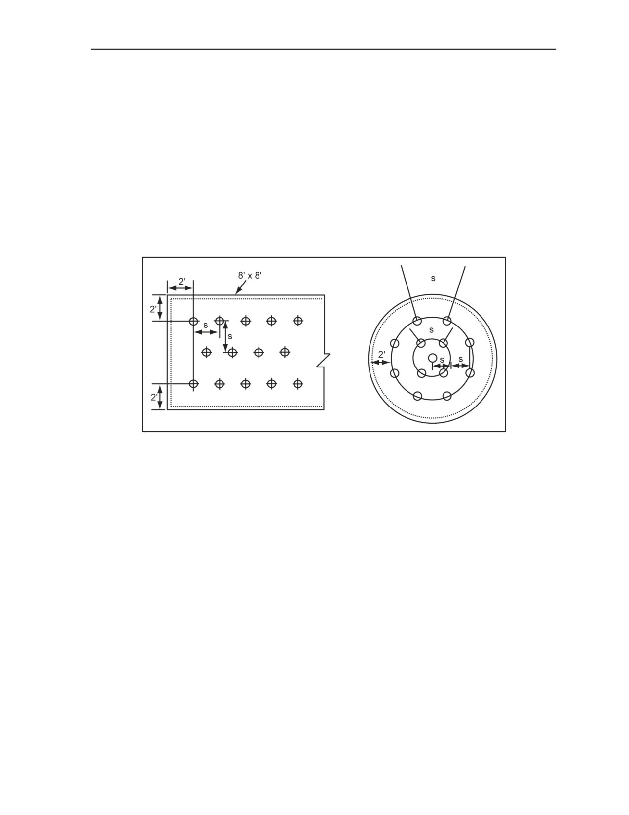
Charge Calculations and Placement
DEPTH
3-93. Charges are placed 1 foot shallower than the required depth to a maximum of 4 feet. If the required
depth is greater than 5 feet, dig the position in two stages, dividing the required depth in half for each stage.
Boreholes are made with an earth auger, wrecking bar, picket driver, or other expedient device.
SPACING
3-94. For rectangular excavations, the boreholes are dug in staggered lines. For circular excavations, the
boreholes are dug in staggered, concentric rings. The spacing (denoted as s) (Figure 3-25) between
boreholes in each line or ring and between lines or rings should be between 1 and 1 1/2 times the depth of
the borehole. All charges should be at least 2 feet inside the proposed perimeter of the excavation. Also, an
8- by 8-inch channel should be dug around the outer perimeter of the proposed excavation with the outer
edge of the channel forming the outer edge of the finished excavation. Figure 3-25 shows layouts for
rectangular and circular excavations.
Figure 3-25. Borehole Layouts
CHARGE SIZE
3-95. To dig foxholes, use 1/4-pound charges of plastic explosive. For large excavations, use charges
between 1/2 and 1 1/2 pounds, depending on spacing and soil characteristics. A test shot is usually
necessary to determine the correct charge size.
CONCEALMENT
3-96. Reduce explosion noise and spoil scatter by leaving any sod in place and covering the site with a
blasting mat. Blasting mats can be improvised by tying tires together with natural or synthetic rope (steel
wire rope is unacceptable) or by using a heavy tarpaulin.
EQUIPMENT DESTRUCTION
3-97. The following paragraphs discuss how to destroy equipment, such as guns and vehicles.
DANGER
Steel-cutting charges produce metal fragments. Proper
precautions should be taken to protect personnel. Failure to
comply may cause death or permanent injury.
11 July 2007
FM 3-34.214
3-33

Chapter 3
WARNING
Beware of potential radiological hazards associated with
ordnance (depleted uranium
[DU] and some weapon system
sights [foreign-tritium]). Take proper protective measures before
and after equipment destruction. Failure to comply could result in
immediate personal injury or damage to equipment.
GUNS
3-98. Gun barrels are destroyed with explosives or their own ammunition. Small components should be
removed or destroyed (such as sights and other mechanisms). The following procedures should be
performed when preparing a gun for demolition:
Block the barrel just above the breach. Solidly tamp the first meter of the bore with earth for
small-caliber guns that use combined projectile-propellant munitions. Load a projectile and aim
the tube to minimize damage if the round is ejected. For heavier guns that use projectiles,
separate from the propellants.
Refer to Table 3-11 for the charge size required for standard barrel sizes. Determine the required
charge size using the following formula (if necessary):
D2
P =
636
where—
P
= quantity of explosive (any HE) (in pounds)
D
= bore size of the barrel (in millimeters)
636 = constant used to compute P
Pack the explosive, preferably composition C4, into the breach immediately behind the tamping.
Place the plastic explosive in close contact with the chamber. Close the breach block as far as
possible, leaving only enough space for the detonating cord to pass without being bent or
broken. Place 15-pound charges on the drive wheels of tracked guns and on the wheels and axles
of towed guns, if time permits. Connect the branchlines in a junction box, or use a ring main.
Simultaneously detonate all charges.
Table 3-11. Gun-Destruction Charge Sizes
Serial
Barrel Size (mm)
Charge Size (lb)
1
76
10
2
105
18
3
120
23
4
155
38
5
203
66
Note. Determine the appropriate charge sizes for barrel sizes not listed by comparing them to
known barrel sizes. For example, use the explosive weight in Serial 3 for a 112-millimeter
barrel (23 pounds) and Serial 4 for a 152-millimeter barrel (38 pounds).
3-34
FM 3-34.214
11 July 2007
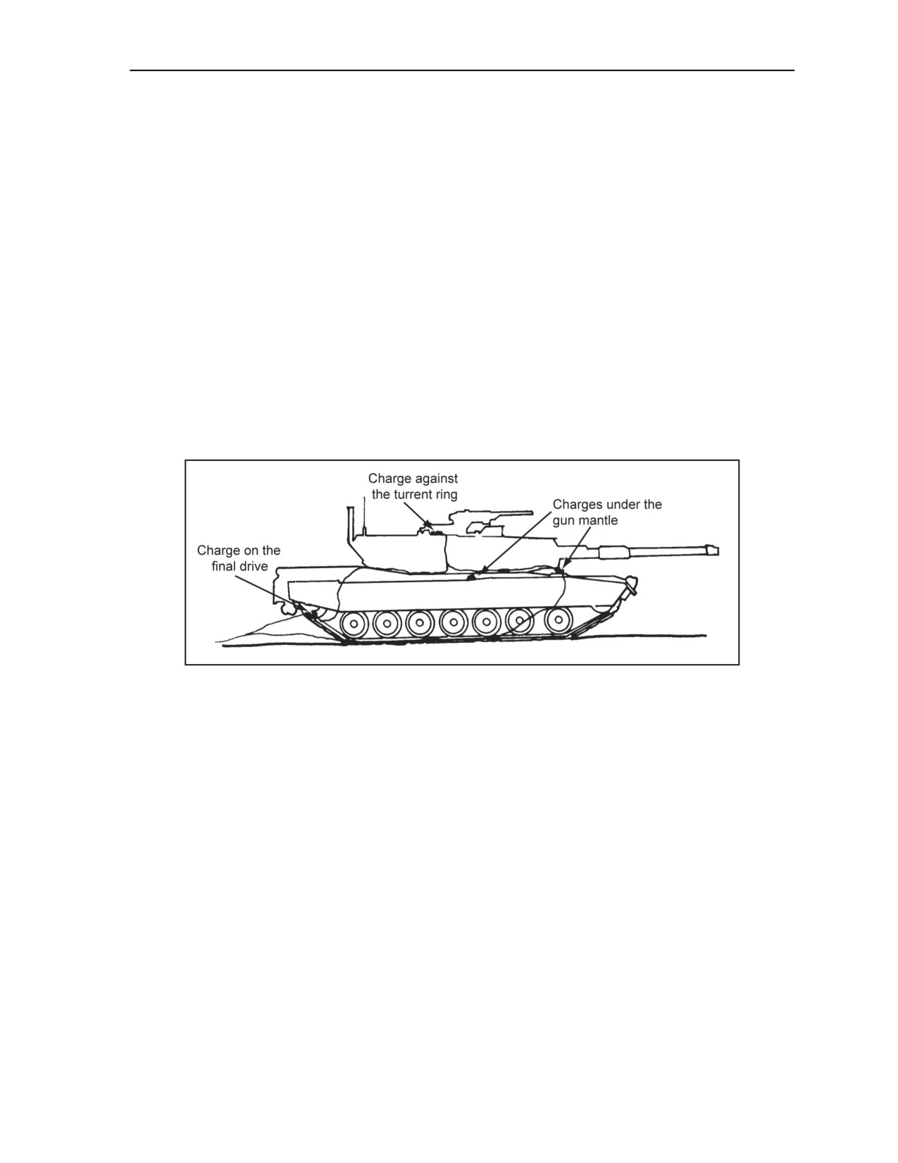
Charge Calculations and Placement
VEHICLES
3-99. To destroy friendly vehicles, refer to the applicable TM. When destroying vehicle components, use
the following priorities:
Priority 1. Carburetor, distributor, fuel pump or injectors, and fuel tanks and lines.
Priority 2. Engine block and cooling system.
Priority 3. Tires, tracks, and suspension system.
Priority 4. Mechanical or hydraulic systems (where applicable).
Priority 5. Differential and transfer case.
Priority 6. Frame.
Armored Fighting Vehicles
3-100. Armored fighting vehicles (AFVs) can be destroyed beyond repair by detonating a 25-pound
charge inside the hull. The charge may be a bulk 25-pound charge or a number of smaller charges placed
on the driving, turret, and gun controls. To increase the amount of damage to the AFV, ensure that the
ammunition within the AFV detonates simultaneously with the other charges and that all hatches, weapons
slits, and other openings are sealed. If it is not possible to enter the AFV, place the two charges under the
gun mantle, against the turret ring, and on the final drive (Figure 3-26). If explosives are not available,
destroy the AFV by using AT weapons or fire or destroy the main gun with its own ammunition.
Figure 3-26. AFV Charge Placement
Wheeled Vehicles
3-101. When using the explosive method, wheeled vehicles can be destroyed beyond repair by wrecking
the vital parts with a sledgehammer or explosives. If HEs are available, 2-pound charges should be used to
destroy the cylinder head, axles, and frame.
3-102. When using the improvised method, the engine oil and coolant should be drained and the engine
ran at full throttle until it seizes. To finish the destruction, burn the vehicle (ignite the fuel in the tank).
UNDERWATER DEMOLITIONS
3-103. See Appendix G for use and placement of underwater demolitions. Appendix G outlines the
techniques, tactics, and procedures for underwater clearance.
11 July 2007
FM 3-34.214
3-35

This page is intentionally left blank.
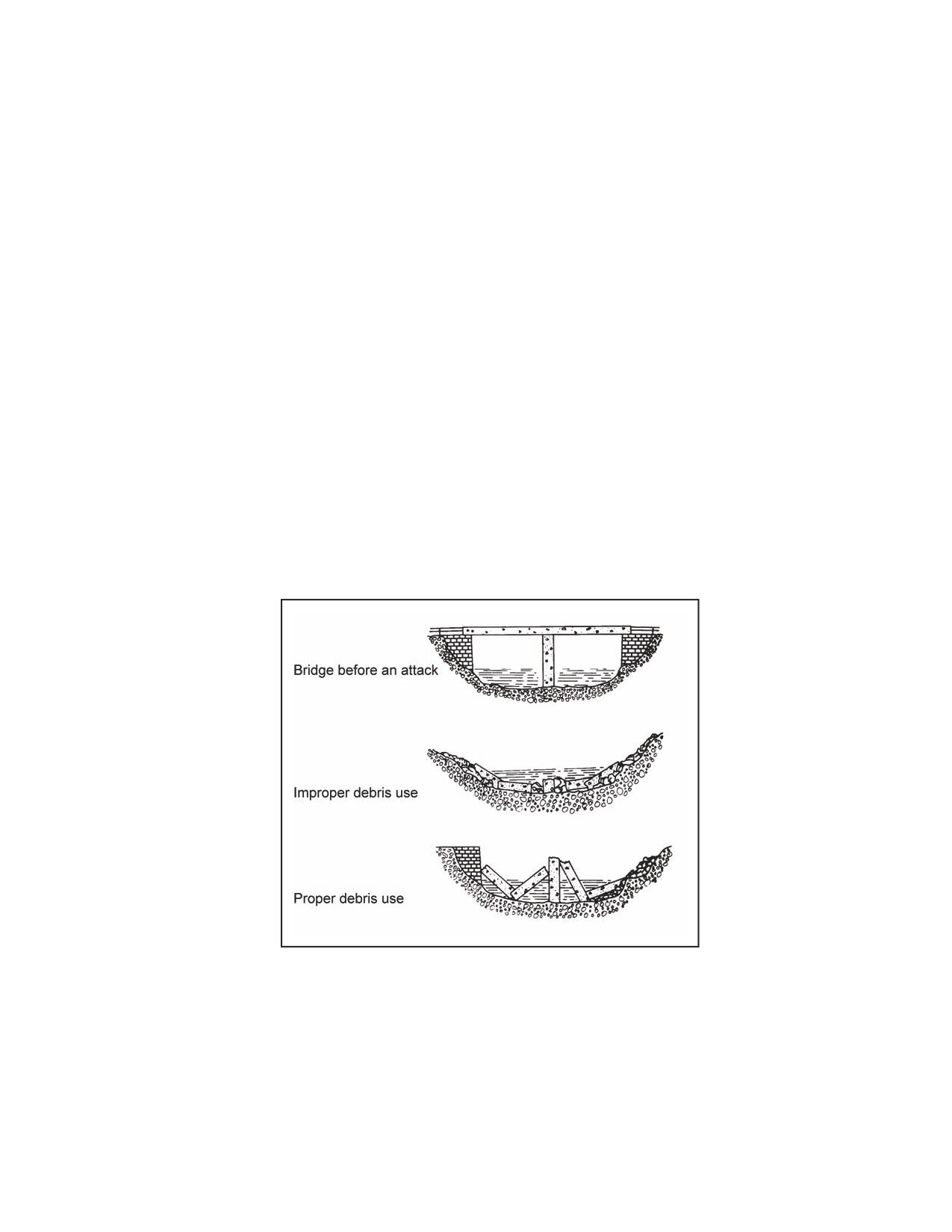
Chapter 4
Bridge Demolition
The purpose of bridge demolition is to create gaps in bridges by attacking key bridge
components. This makes gaps large enough to make repairs uneconomical and to
force the enemy to construct other bridges on other sites. The minimum gap required
must exceed the assault bridging capability of the enemy by 5 meters. For planning
purposes, use 25 meters as the minimum gap size, but 35 meters is preferred. The
complete demolition of a bridge usually involves destroying all the components
(spans, piers, and abutments). Complete demolition may be justified when the terrain
forces the enemy to reconstruct a bridge on the same site. However, complete
destruction is not required to meet the tactical objective. The attack method that
achieves the tactical goal should be selected with a minimum expenditure of
resources.
BRIDGE DEBRIS
4-1. Debris may cause enemy forces serious delays, if it obstructs the gap (Figure 4-1). Debris also
provides excellent concealment for mines and booby traps. Whenever possible, demolish bridges in such a
way that the resulting debris hinders reconstruction.
Figure 4-1. Debris Use
BRIDGE CATEGORIES
4-2. The first step in any efficient bridge demolition is to categorize the bridge correctly. The term
categorization has been adopted to avoid confusion with classification, which is concerned with the load-
carrying capacity of bridges. The correct categorization of bridges, coupled with an elementary knowledge
of bridge design, allows you to select a suitable attack method. All bridges fit into one of the following
three categories: simply supported, miscellaneous, and continuous.
11 July 2007
FM 3-34.214
4-1
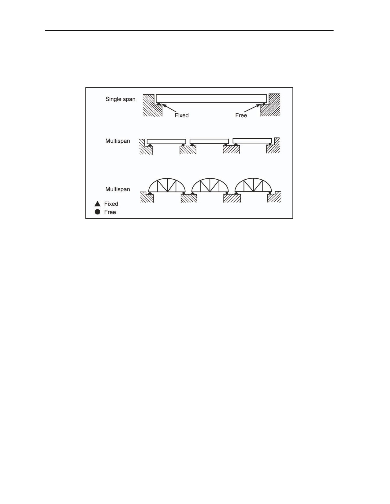
Chapter 4
SIMPLY SUPPORTED
4-3. In simply supported bridges, the ends of each span rest on the supports, and there are no intermediate
supports. The free bearing conditions shown in Figure
4-2 represent any bearing that allows some
horizontal movement (for example, roller bearings, sliding bearings, and rubber bearing pads).
Figure 4-2. Simply Supported Bridges
MISCELLANEOUS
4-4. Miscellaneous bridges form a small portion of bridge structures. The theoretical principles governing
these bridges determine the appropriate attack methods. Examples of bridges in this category are
suspension, lift, and cable-stayed bridges.
CONTINUOUS
4-5. If a continuous bridge does not fit the miscellaneous category and is not simply supported, categorize
it as a continuous bridge. Hence, continuous has a wider meaning than multispan, or continuous-beam
bridges, as is normally implied.
ATTACK TYPES
4-6. When designing a bridge demolition, the first priority is to create a gap. This may require one or two
attacks to accomplish. Further actions to improve the obstacle may follow if the situation permits.
BOTTOM ATTACK
4-7. In a bottom attack, a hinge forms at the top. As the span falls, the cut ends at the bottom move
outward. The span may form a three-pin arch and fail to fall completely if the distance the cut ends must
move is greater than the total end clearance (denoted as E) between the span ends and the pier or abutment
faces (Figure 4-3). If a three-pin arch situation is likely, do not attempt a bottom attack.
4-2
FM 3-34.214
11 July 2007
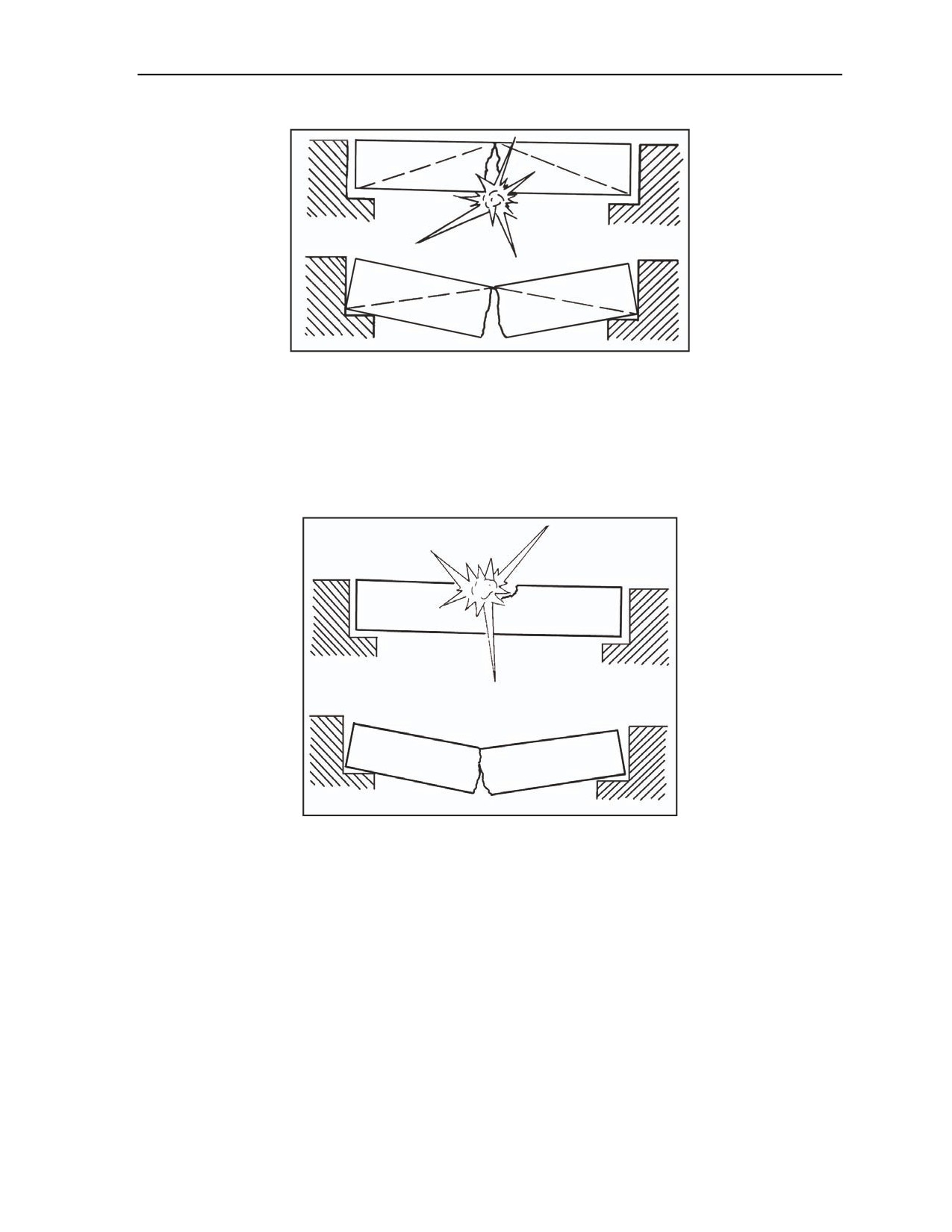
Bridge Demolition
Figure 4-3. Three-Pin Arch Effect
TOP ATTACK
4-8. In a top attack, a hinge forms at the bottom. As the span falls, the cut ends at the top move inward.
Some bridges may jam along the faces of the cut before the ends of the span fall off the abutments, forming
a cranked beam (Figure 4-4). The length of span (denoted as LC) removed at the top should be enough to
prevent the formation of a cranked beam.
Figure 4-4. Cranked-Beam Effect
SUCCESSFUL BRIDGE DEMOLITIONS
4-9. There are two minimum conditions for successful bridge demolition. They are—
Condition 1 (a proper collapse mechanism design). Under normal conditions, a bridge is a
stable structure. In bridge demolitions, the goal is to destroy the appropriate parts of a bridge so
that it becomes unstable and collapses under its own weight. In other words, a collapse
mechanism is formed. This may involve either cutting completely through all structural
members or creating points of weakness in certain parts of the bridge. Figure 4-5, page 4-4,
shows an improper collapse mechanism and the hinges that have not been formed. At times,
making bridges unstable by attacking their piers rather than their superstructures is easier, but it
is still possible for bridges not to collapse, even though they lose the support provided by one or
more of their piers. To avoid this type of demolition failure, place the charges on the structural
members of the superstructure immediately above the piers being attacked.
11 July 2007
FM 3-34.214
4-3
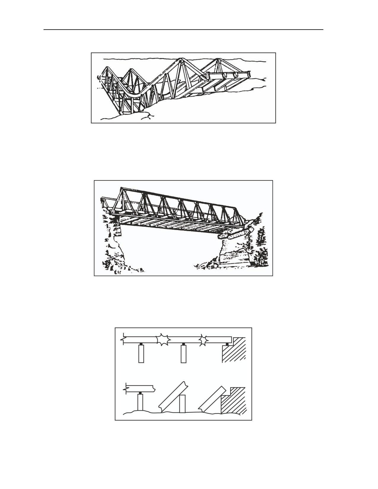
Chapter 4
Figure 4-5. Improper Collapse Mechanism and Hinges
Condition 2 (an attacked span that moves freely and far enough under its weight and
creates the desired obstacle). Figure
4-6 shows a bridge demolition where the collapse
mechanism has formed but where it has failed to form the desired obstacle because the bridge
span has jammed before moving far enough. To complete the demolition in this example,
remove only a small portion of the abutment to allow the span to swing down freely.
Figure 4-6. Jammed Bridge Span
COLLAPSE MECHANISM TYPES
4-10. Figures 4-7 through 4-9 show the three basic collapse mechanisms. The three collapse mechanisms
are the seesaw, beam, and member without support.
Figure 4-7. Seesaw Collapse Mechanism
4-4
FM 3-34.214
11 July 2007
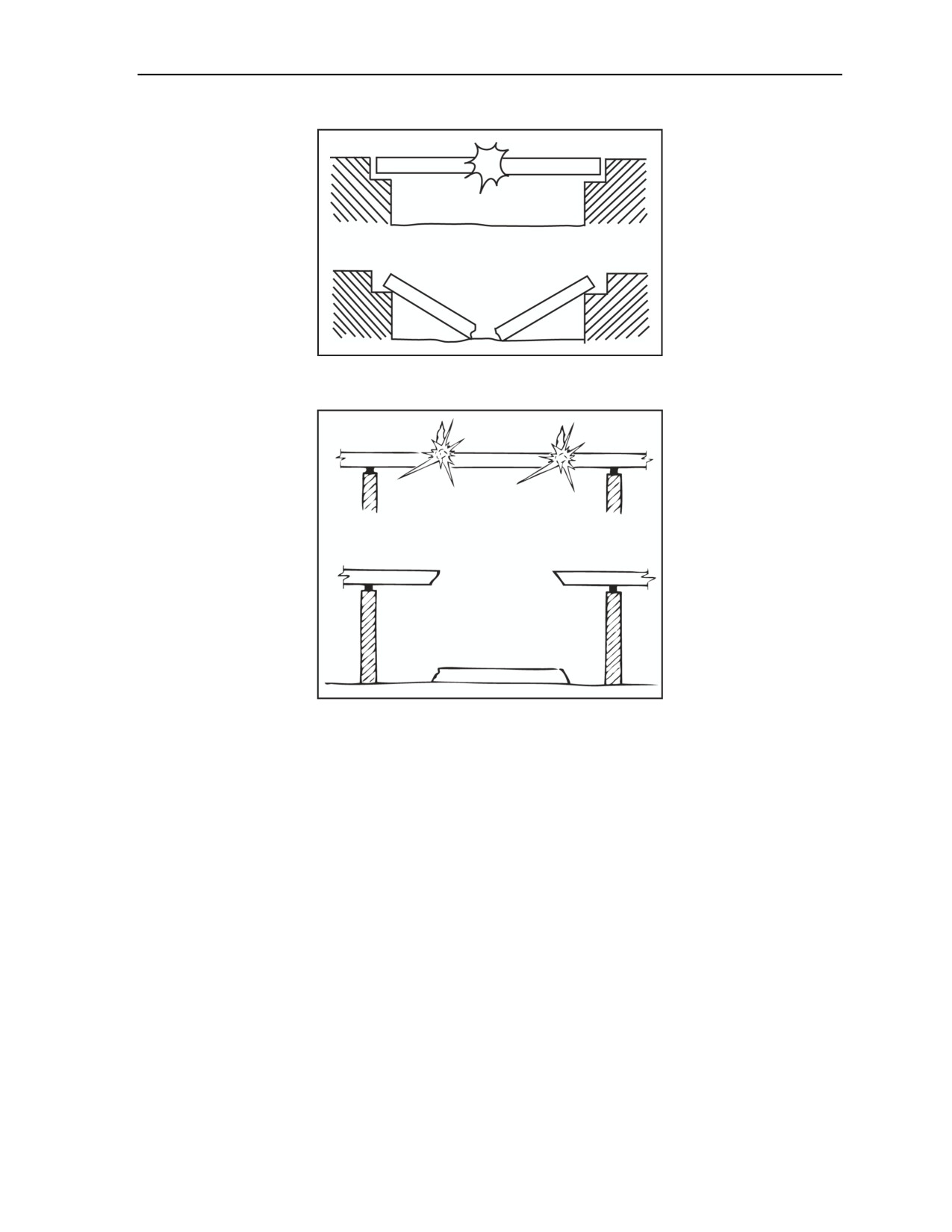
Bridge Demolition
Figure 4-8. Beam Collapse Mechanism
Figure 4-9. Member Without a Support Collapse Mechanism
EFFICIENT DEMOLITION METHODS
4-11. To ensure that a demolition achieves collapse with reasonable economy, consider the factors required
to achieve an efficient demolition. The best balance between these factors will depend on the particular
demolition under consideration. An efficient demolition should—
Achieve the desired effect.
Use the minimum amount of resources (time, manpower, and explosives).
Observe the proper priorities. The demolition reconnaissance report clearly states the priorities
and separately lists the requirements for priority 1 actions and priority 2 improvements (the
priorities are explained below). If enough gap will result by attacking bridge spans, do not
perform the priority 2 improvements unless the report specifies complete destruction or an
excessively long gap. If the total gap spanned by a bridge is too small to defeat enemy assault
bridging, consider the site as an unsuitable obstacle unless the gap can be increased. Engineer
efforts may be better applied elsewhere. To improve an obstacle, increase the gap by
demolishing the abutments and building craters on the immediate approaches. In this case, attack
nearby bypass sites (by placing mines and craters).
Priority 1. The desired obstacle should be created. The minimum gap required is 5 meters
greater than the assault bridging capability of the enemy. Ideally, demolition should be
accomplished with the first attempt. However, many reinforced- or prestressed-concrete
11 July 2007
FM 3-34.214
4-5
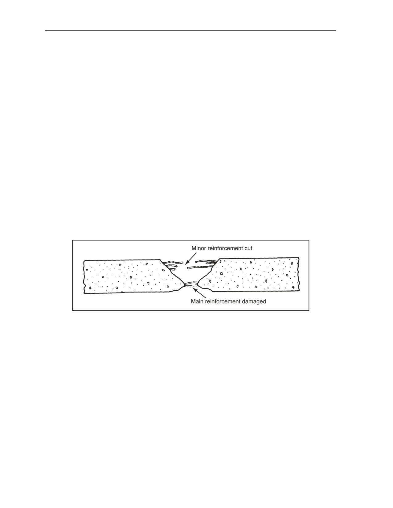
Chapter 4
bridges may require two-stage attacks. Attacking the friendly side of spans will permit
economical reconstruction of the bridge at a later date, if necessary.
Priority 2. Improvements to the gap should be made. This activity is performed only when
it is specified on the demolition reconnaissance report. When no reconnaissance report has
been issued and time permits, perform improvements in the sequence specified below.
Deviation from this sequence should only be made under exceptional circumstances or
when directed to do so by the responsible commander. The standard sequence of demolition
is to destroy and mine the blown abutment, to lay mines in likely bypasses, to blast craters
and lay mines in likely approaches, and to destroy the piers.
CONCRETE-STRIPPING CHARGES
4-12. Concrete-stripping charges are bulk, surface-placed charges designed for removing concrete from
reinforced-concrete beams or slabs and exposing the steel reinforcement. Although these charges cause
some damage to the reinforcing steel, the extent of this damage cannot be predicted. These charges are
effective against reinforced-concrete beams or slabs up to 2 meters thick.
Charge Effects
4-13. Figure 4-10 shows the effect of the concrete-stripping charge. Using the proper charge size for the
thickness of the target will—
Remove all concrete from above the main reinforcing steel.
Remove all concrete from below the main reinforcing steel (spalling).
Damage the main reinforcing steel to some extent.
Destroy the minor reinforcing steel near the surface under the charge.
Figure 4-10. Effect of a Concrete Stripping Charge
Charge Calculations
4-14. For all simply supported concrete bridges, removing all concrete over the required length of the span
removed will cause collapse. For beam or slab bridge spans (T beam and I beam bridges), determine the
charge sizes for the beams or slabs separately. The following procedure is used for determining charge
sizes for simply supported spans (see Figure F-12, page F-10, for an example calculation):
Calculate the mass of the charge required.
P = (3.3h + 0.5)3 (3.3)
where—
P
= required charge size in pounds of TNT per meter of bridge width
3.3 = constant to determine P
h
= beam or slab plus roadway depth in meters (minimum is 0.3 meters and maximum is
2 meters)
0.5 = constant to determine P
4-6
FM 3-34.214
11 July 2007
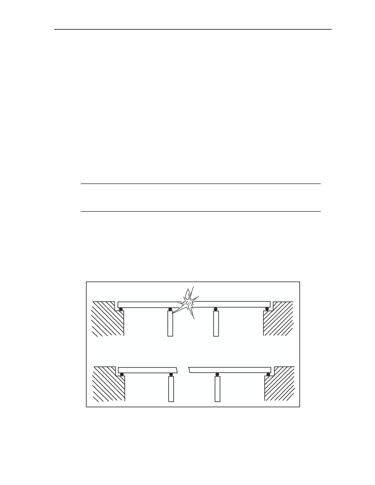
Bridge Demolition
Calculate the width of the required ditch. (The charge will produce a ditch across the width of
the bridge.) Determine the width of this ditch using the following formula:
Wd = 2h + 0.3
where—
Wd
= ditch width (in meters)
h
= overall roadway or beam or slab depth (in meters)
Compare the required Wd with the required LC, and take the appropriate action.
If LC is equal to or less than Wd, use one row of charges as specified by P.
If LC is greater than Wd but less than twice Wd, increase the size of the charge by
10 percent.
If LC is twice the Wd, double the charge and place them in two lines side by side.
Place charges in a continuous line across the full width of the bridge at the point of attack.
Ensure that the shape of the end cross section of the charge is such that the width is between one
and three times the height of the charge.
Tamp the charges, if required.
Note. No tamping is required for the concrete-stripping charge as calculated. If tamping with two
filled sandbags per pound of explosive, the calculated mass of charge should be reduced by one
third.
UNSUCCESSFUL BRIDGE DEMOLITIONS
4-15. A no-collapse mechanism and jamming are two possible reasons for unsuccessful bridge
demolitions. The formation of cantilevers (Figure 4-11) is a typical example of a no-collapse mechanism
being formed. The likelihood of this occurring is high when attacking continuous bridges. The span, once
moved by the collapse mechanism, jams before moving far enough to create the desired obstacle. The most
likely causes of jamming are the formation of a three-pin arch or a cranked beam (Figure 4-12, page 4-8).
When attacking bridge spans, always consider the possibility of jamming during bottom and top attacks.
Figure 4-11. Cantilever Effect
11 July 2007
FM 3-34.214
4-7
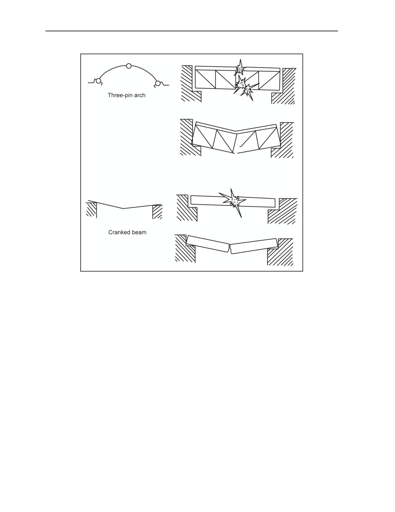
Chapter 4
Figure 4-12. Causes of Jamming
SIMPLY SUPPORTED BRIDGES AND CONTINUOUS BRIDGES
4-16. The external appearance of a bridge can sometimes be deceptive. Whenever possible, consult
construction drawings to determine the correct bridge category. If drawings are not available and there is
any uncertainty about the category to which the bridge belongs, assume the bridge is of continuous
construction. Since more explosive is necessary to demolish a continuous bridge, assume that a continuous
construction will provide more than enough explosive to demolish a bridge of unknown construction. The
following describes some differences between simply supported and continuous bridges (Figure 4-13):
Continuity. In simply supported bridges, the entire superstructure is composed of a span or
multiple spans supported at each end. The main structural members (individual spans) meet end-
to-end, and each intermediate pair of ends is supported by a pier. The single ends are supported
by the abutments. In continuous bridges, the main structural members are formed into one piece
and do not have breaks over the piers, if any are present.
Construction depth. In multispan, simply supported bridges, the construction depth of the span
may decrease at the piers. In continuous bridges, construction depth frequently increases at the
piers.
Flange thickness. In simply supported, steel-girder bridges, the thickness of the flange
frequently increases at the midspan. In continuous bridges, the flange size frequently increases
over the piers.
Bearing. In multispan, simply supported bridges, two lines of bearing is needed at the piers. In
continuous bridges, only one is needed.
4-8
FM 3-34.214
11 July 2007
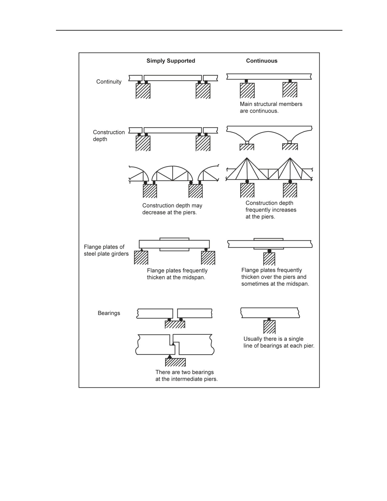
Bridge Demolition
Figure 4-13. Span Differences
4-17. More explosive is necessary to demolish a continuous bridge, assuming that a continuous
construction will provide more than enough explosive to demolish a bridge of unknown construction. To
use the tables in Appendix H correctly, decide whether the bridge is in the simply supported, continuous, or
miscellaneous category and follow the procedures as outlined in the appropriate paragraph.
11 July 2007
FM 3-34.214
4-9
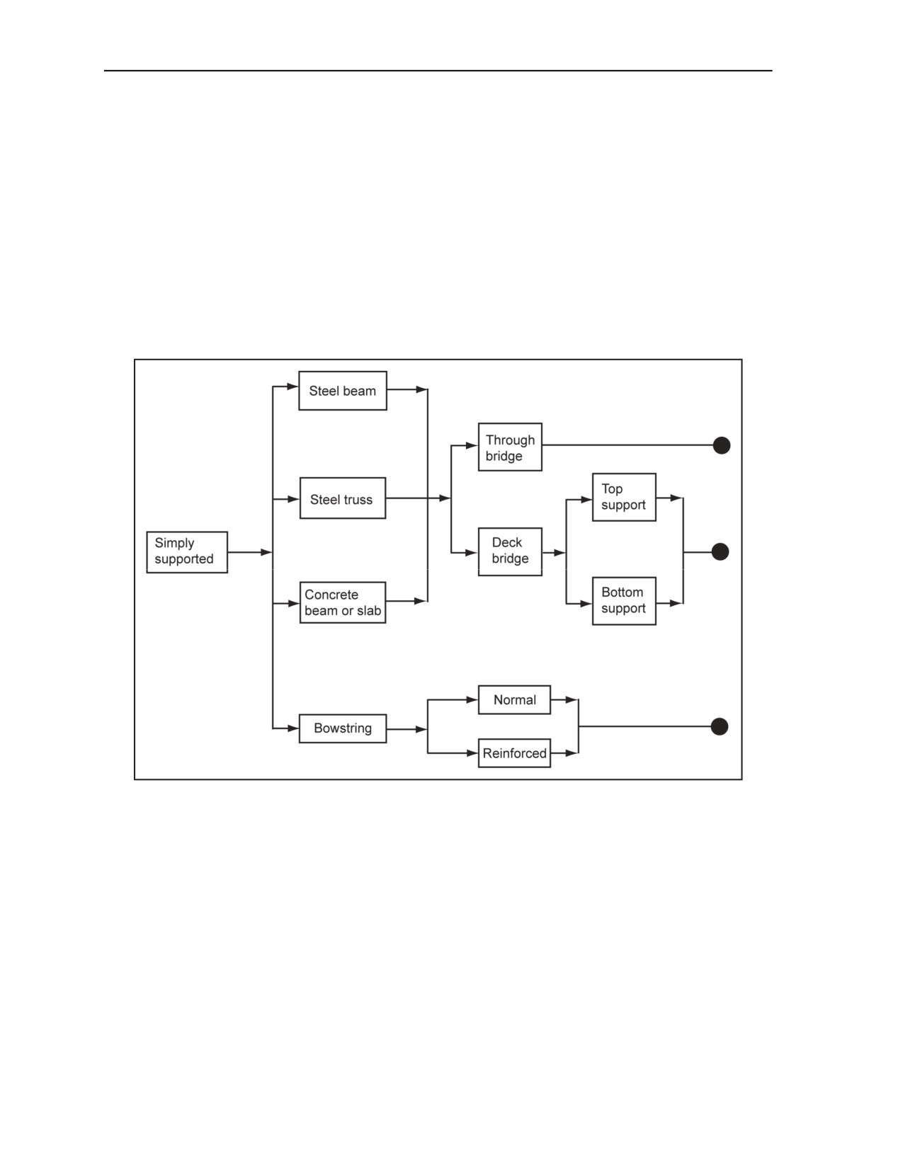
Chapter 4
SIMPLY SUPPORTED BRIDGES
4-18. Figure 4-14 is a categorization chart for simply supported bridges. This chart is entered from the left,
and the lines and arrows are followed across to the right. The path selected must include all categorization
terms applicable to the simply supported bridge that is planned to be demolished. There are four main
subcategories:
Steel beam.
Steel truss.
Concrete beam or slab.
Bowstring.
4-19. The first three are further subdivided into deck bridges, which carry their loads on top of the main
structural members and through bridges. When dealing with deck bridges, note the locations of the bearing
(supporting the top or bottom chord or flange); this will influence the possibility of jamming.
Figure 4-14. Categorization Chart for Simply Supported Bridges
Steel-Beam Bridges
4-20. Steel-beam bridges may be constructed of normal steel-beam, plate-girder, or box-girder spans.
Figure 4-15 shows typical cross sections of these spans. For an example calculation, see Figure F-13,
page F-11.
4-10
FM 3-34.214
11 July 2007
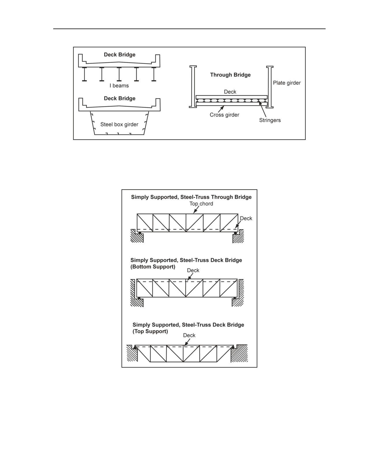
Bridge Demolition
Figure 4-15. Typical Cross Sections of Steel-Beam Bridges
Steel-Truss Bridges
4-21. Figure 4-16 shows the side elevations for three normal steel-truss spans. Note that all truss bridges
have diagonal members in the trusses.
Figure 4-16. Side Elevation of Steel-Truss Bridges
Concrete-Beam or Slab Bridges
4-22. For categorization purposes, distinguish between reinforced- and prestressed-concrete bridges,
because the methods of attack are the same for both. Figure 4-17, page
4-12, shows midspan,
cross-sectional views of these bridge types. At midspan, the majority of steel reinforcing rods or tendons
are located in the bottom portion of the superstructure. The attack methods detailed in Appendix H take this
reinforcing condition into account.
11 July 2007
FM 3-34.214
4-11
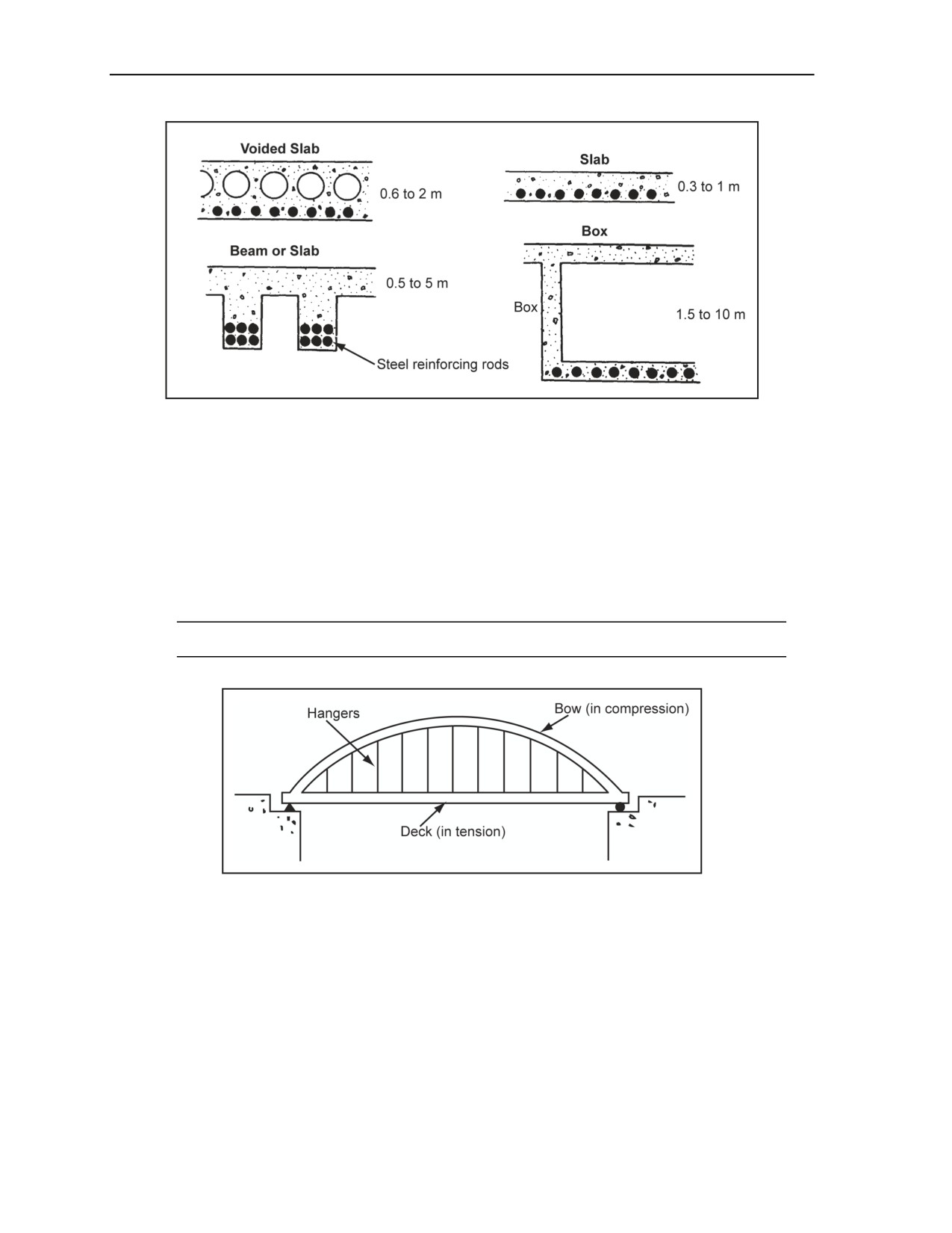
Chapter 4
Figure 4-17. Midspan, Cross-Sectional Views of Typical Concrete Bridges
Bowstring Bridges
4-23. Figure 4-18 shows the features of a normal bowstring bridge. The features of this bridge include the
following:
The bow is in compression.
The bow may be a steel beam, box girder, concrete beam, or steel truss. The depth (thickness) of
the bow is larger than or equal to the depth of the support members of the deck.
The deck acts as a tie and resists the outward force applied by the bow.
The deck is designed as a weak beam supported by the hangers.
Note. There is no diagonal bracing between the hangers.
Figure 4-18. Normal Bowstring Bridge
4-24. Occasionally, the bow and hangers are used to reinforce a steel-beam or -truss bridge. This bridge
type is categorized as a bowstring reinforced-beam or reinforced-truss bridge (Figure 4-19). In this type of
bridge, the depth of the bow will always be less than the depth of the support members of the deck.
4-12
FM 3-34.214
11 July 2007
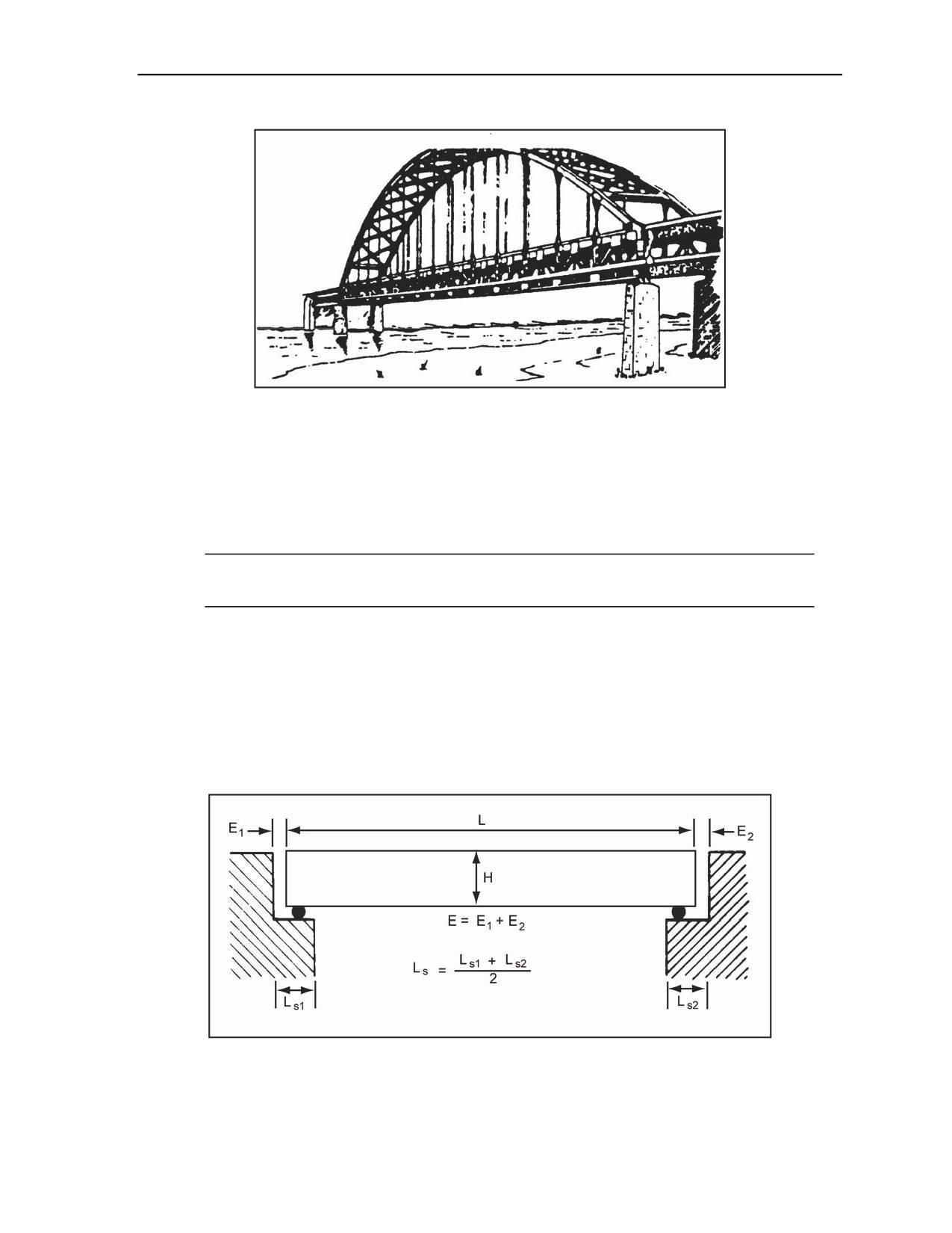
Bridge Demolition
Figure 4-19. Bowstring-Reinforced Truss Bridge
Reconnaissance
4-25. For simply supported bridges, use the following reconnaissance procedures:
Categorize the bridge.
Measure the bridge using the following measurements with Figure 4-20 as an example:
Length (L). Measure the length of the span to be attacked in meters.
Note. This distance is not the clear gap, but the length of the longitudinal members that support
the deck from end to end.
Depth (H). Measure the depth of the beam, truss, or bow in meters (include the deck with
the beam or truss measurement).
Total end clearance (E). Total the amount of end clearance at both ends of the span in
meters.
Average length of the bearing supports (LS). Measure the average length of the bearing
supports from the ends of the spans to the faces of the abutments or piers in meters.
Determine the attack method (see Appendix H).
Determine the critical dimensions of the span required for charge calculations.
Figure 4-20. Measurements of Simply Supported Spans
11 July 2007
FM 3-34.214
4-13
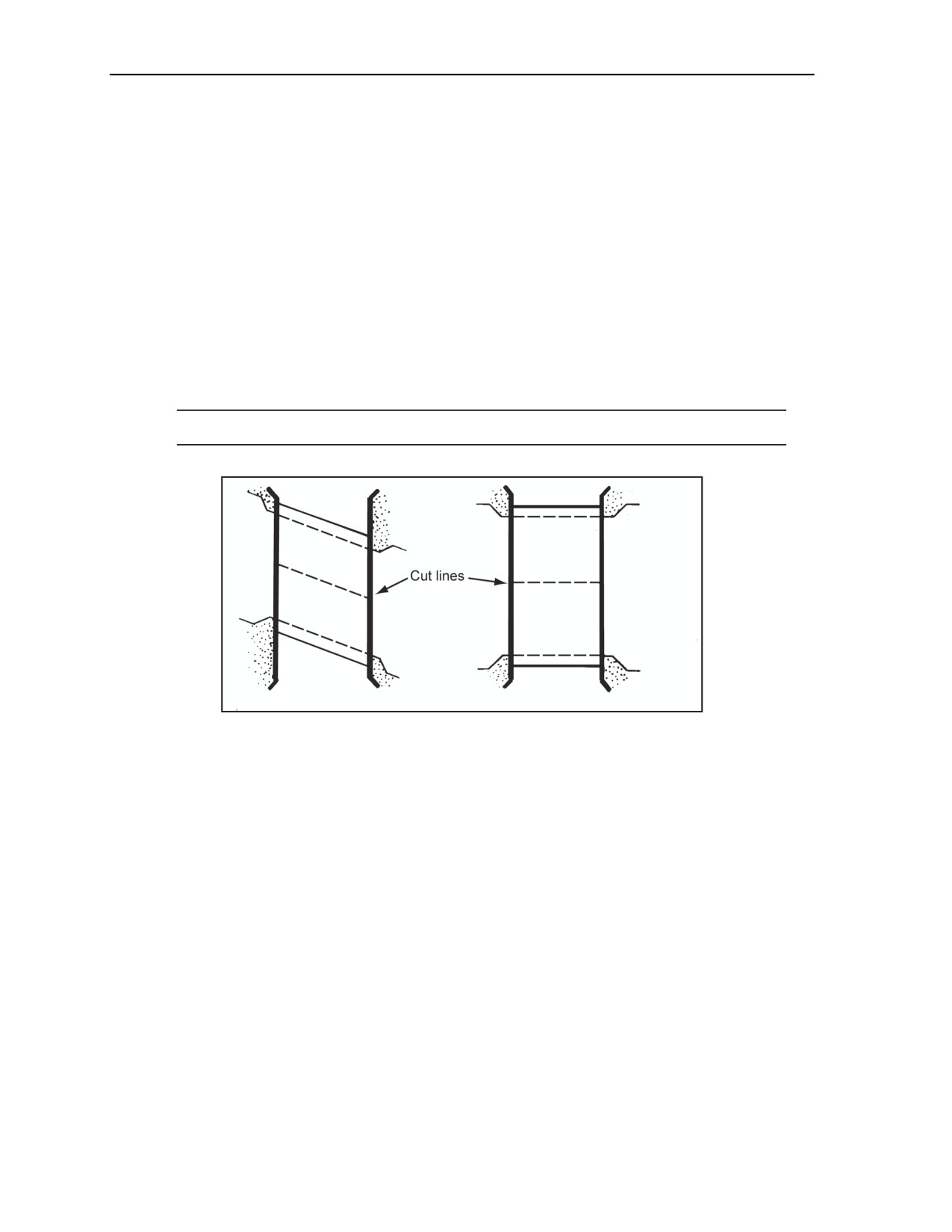
Chapter 4
Attack Considerations
4-26. Two considerations apply when attacking a simply supported span. They are the point of attack and
the line of attack.
Point of Attack
4-27. Simply supported bridges should be attacked at or near the midspan. This is done because—
Bending movements are maximum at the midspan.
The likelihood of jamming during collapse is reduced if the bridge is attacked at the midspan.
Line of Attack
4-28. The line of attack should be parallel to the lines of the abutments (Figure 4-21). This reduces the risk
that the two parts of the span will slew in opposite directions and jam. Do not employ any technique that
induces a twist in the bridge. If the line of attack involves cutting across transverse beams, reposition the
line of attack to cut between the transverse beams.
Note. For a sample calculation, see Figure F-14, page F-12.
Figure 4-21. Line of Attack
Attack Methods
4-29. See Appendix H, Table H-4, pages H-4 through H-8. Table H-4 lists in recommended order, by
bridge category, the attack methods likely to produce the most economical demolition. Within each
category are variations to accommodate the differences in construction materials, span configurations, load
capacities (road, rail, or both), and gap and abutment conditions. The three recommended ways of attacking
simply supported spans are bottom, top, and angled attacks. In all cases, ensure that jamming cannot occur
during collapse. Use Table H-4 to determine the charge location.
Bottom Attack Method
4-30. Use the bottom attack method whenever possible; it leaves the roadway open and enables you to use
the bridge, even when demolitions are at a ready-to-fire state (state 2). Reinforced and prestressed (tension)
beams are very vulnerable to a bottom attack, because the steel cables and reinforcing bars run along the
bottom portion of the beam and are covered by less concrete. The major disadvantages of the bottom attack
are the increased amount of time and effort necessary for placing and inspecting the charges. Because it is
generally impracticable to place enough explosive below a reinforced or prestressed slab to guarantee a cut
deeper than 0.15 meter, use the top or angled attacks listed in Table H-4 for these types of bridges. When
Table H-4 lists a bottom attack, determine the required end clearance (ER) from Table H-1, page H-1, to
prevent jamming. If E is greater than ER, jamming will not occur. If E is less than ER, use a top or angled
4-14
FM 3-34.214
11 July 2007

Bridge Demolition
attack or destroy one abutment at the places where jamming would occur. Figure F-13, page F-11, explains
the method for bottom attack calculations.
Top Attack Method
4-31. See Appendix H. When Table H-4, page H-4, lists a top attack, LC must be removed from the top of
the bridge to prevent jamming. From Table H-2, page H-2, determine LC. In a V-shaped section, remove LC
along the full depth of the target. For reinforced-concrete bridges, use a concrete-stripping charge
(discussed earlier in this chapter) to remove LC from the top of the bridge. This action, by itself, should
cause collapse. There is no requirement to cut steel reinforcing rods. Figure F-14 shows the method for top
attack calculations.
Angled Attack Method
4-32. For angled attacks, cut all members (span, handrails, service pipes, and so forth) of the bridge. The
angle of attack should be made about 70° to the horizontal to prevent jamming. The location of the charge
should be between the midspan point and a point L/3 from the end (Figure 4-22). Although an angled attack
is effective on any bridge type, it is essential when the bridge must be kept open to traffic or when there is
ample time to prepare demolitions.
Figure 4-22. Location of an Angled Charge
CONTINUOUS BRIDGES
4-33. Figure 4-23, page 4-16, is a categorization chart for continuous bridges. This chart is used like the
chart for simply supported bridges. There are six main subcategories: cantilever, cantilever and suspended
span, beam or truss, portal, arch, and masonry arch. The first five categories differentiate between steel and
concrete construction, because each material has a different attack method. If a continuous bridge is of
composite construction (for example, steel beams supporting a reinforced-concrete deck), the material that
comprises the main, longitudinal, load-bearing members will determine the attack method.
11 July 2007
FM 3-34.214
4-15
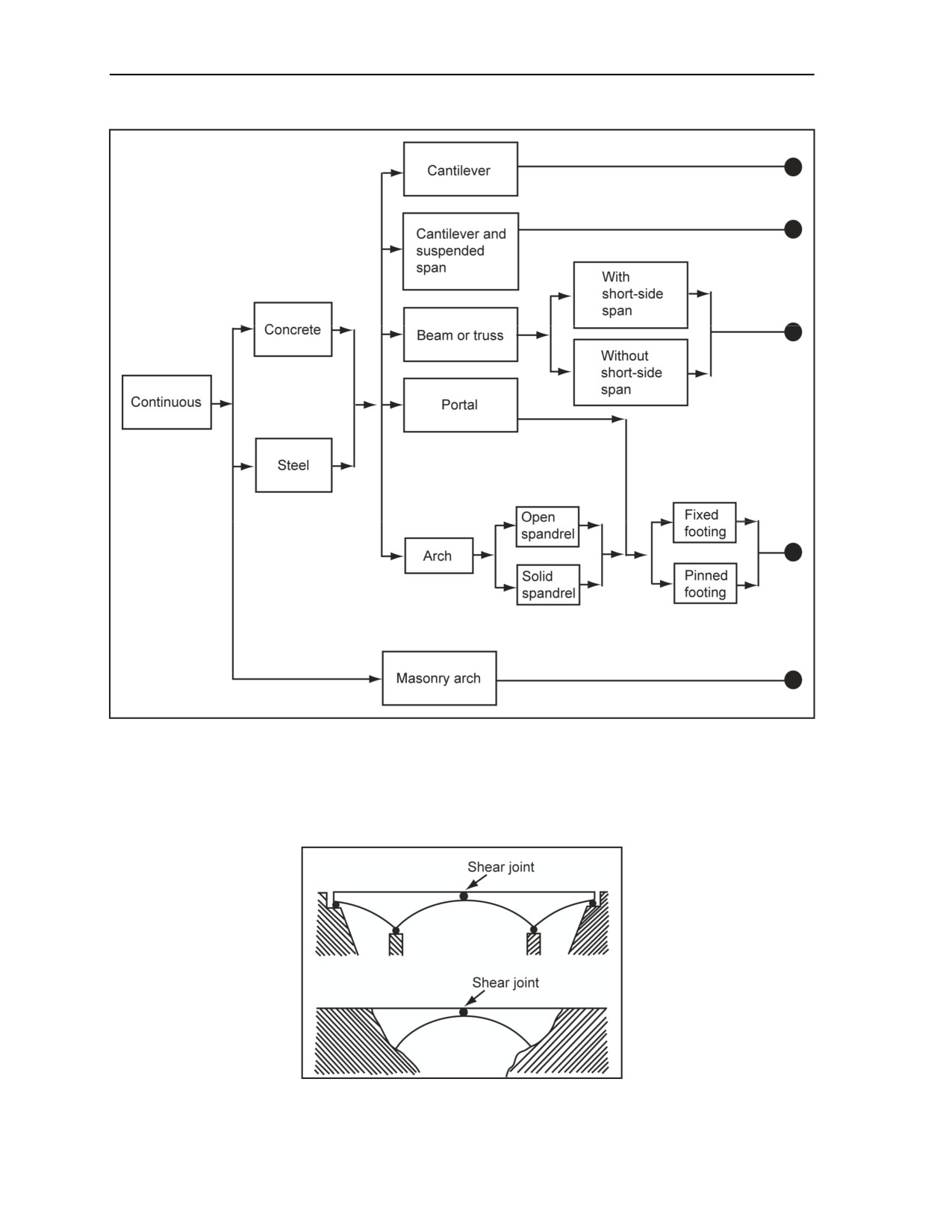
Chapter 4
Figure 4-23. Continuous Bridges Categorization Chart
Cantilever Bridges
4-34. A cantilever bridge (Figure 4-24) has a midspan shear joint. The full lengths of the anchor spans may
be built into the abutments, making the cantilever difficult to identify.
Figure 4-24. Cantilever Bridges
4-16
FM 3-34.214
11 July 2007
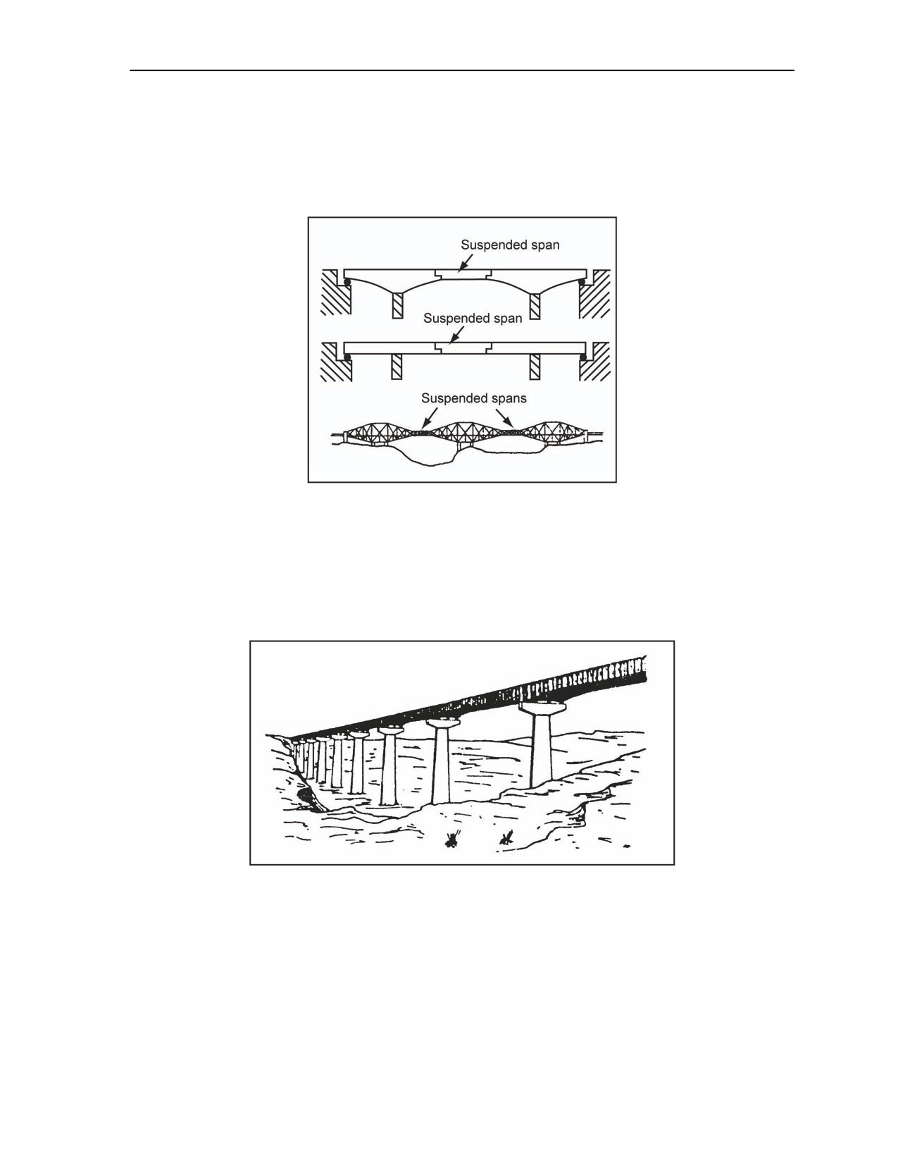
Bridge Demolition
Cantilever and Suspended-Span Bridges
4-35. If a cantilever bridge incorporates a suspended span (Figure 4-25) that is at least 5 meters longer than
the enemy assault bridging capability, this section of the bridge should be attacked. This requires less
preparation. Because suspended spans are simply supported, the attack method described for simply
supported bridges should be used (Table H-4, pages H-4 through H-8).
Figure 4-25. Cantilever and Suspended Span Bridges
Beam or Truss Bridges
4-36. For beam or truss bridges (Figure 4-26, Figure 4-27, page 4-18, and Figure 4-28, page 4-18),
differentiate between those bridges with spans of similar lengths and those with short-side spans because
this affects the attack method. A short-side span is one that is less than three quarters of the length of the
next adjacent span.
Figure 4-26. Steel-Beam Bridge Without a Short-Side Span
11 July 2007
FM 3-34.214
4-17
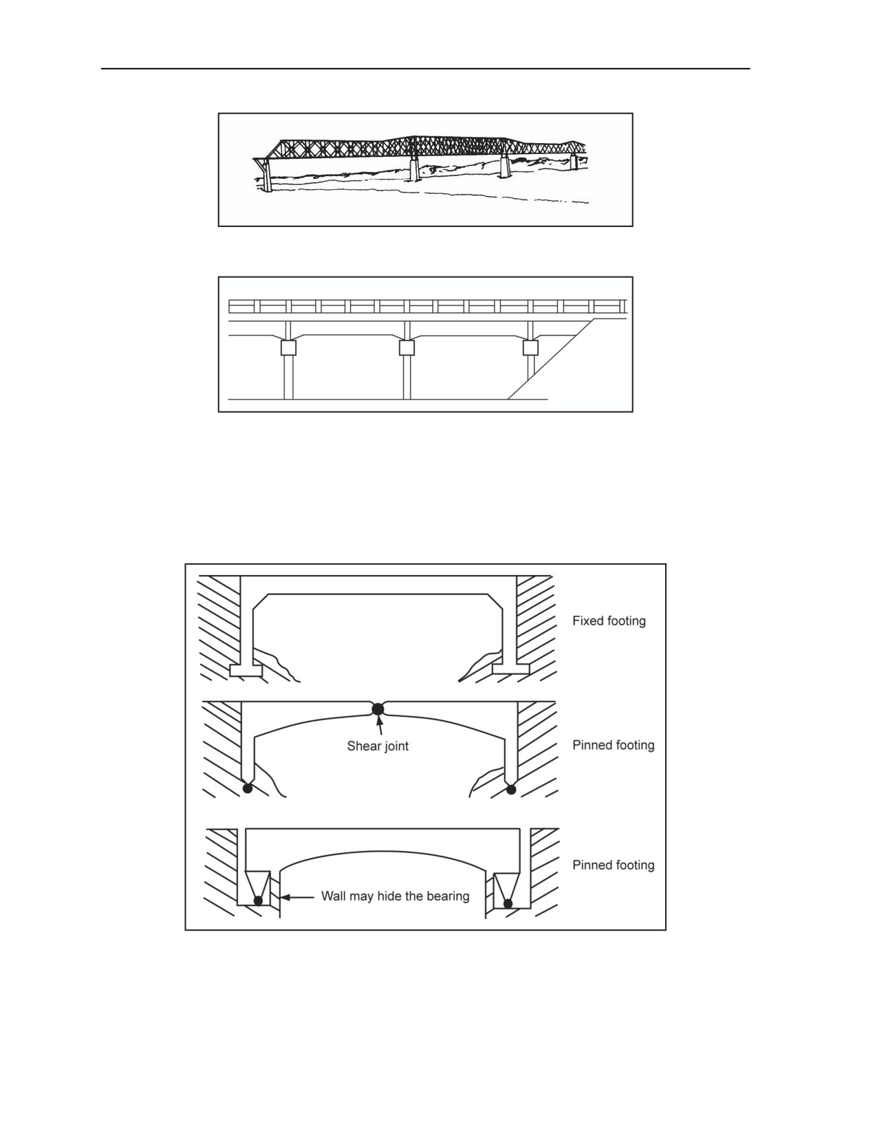
Chapter 4
Figure 4-27. Steel-Truss Bridge With a Short-Side Span
Figure 4-28. Steel-Beam Bridge With a Short-Side Span
Portal Bridges
4-37. For portal bridges (Figure 4-29), differentiate between those with fixed footings and those with
pinned footings because this affects the attack method. If the footing type cannot be determined, assume
that it has fixed footings. Portal bridges, as opposed to arch bridges, lack a smooth curve between the
bearing point of the span and the span itself.
Figure 4-29. Typical Portal Bridges
4-18
FM 3-34.214
11 July 2007
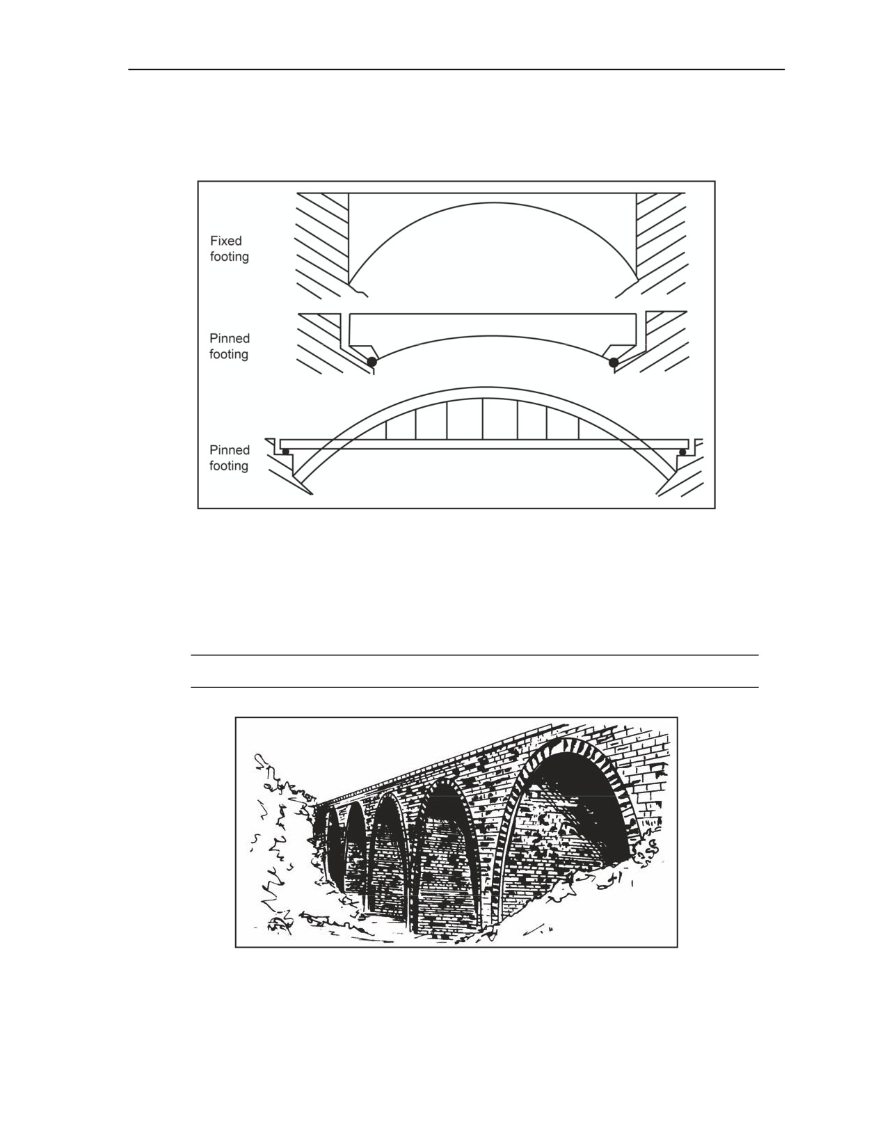
Bridge Demolition
Arch Bridges
4-38. In arch bridges (Figure 4-30), determine whether the bridge has an open or solid spandrel and fixed
or pinned footings. Again, when in doubt, assume that it has fixed footings.
Figure 4-30. Arch Bridges
Masonry-Arch Bridges
4-39. Masonry-arch bridges (Figure 4-31) should be identified by their segmental arch ring. It is easy to
mistake a reinforced-concrete bridge for a masonry arch bridge because many reinforced-concrete bridges
have masonry faces. The underside of the arch should always be checked. The underside is rarely faced on
reinforced-concrete bridges.
Note. For an example calculation, see Figure F-15, page F-13.
Figure 4-31. Masonry-Arch Bridge
11 July 2007
FM 3-34.214
4-19