MANUAL OF NATO SAFETY PRINCIPLES FOR THE STORAGE OF MILITARY AMMUNITION AND EXPLOSIVES (May 2010) - page 9

AASTP-1
(Edition 1)
(d)
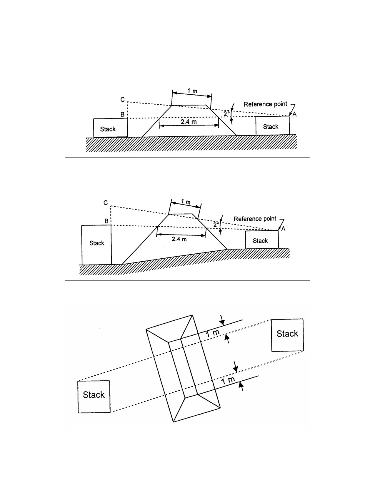
On sloping terrain when the stacks are contiguous line AC must pass through at least 1.0 m
barricade material or undisturbed natural earth.
(e)
On sloping terrain when two stacks are not contiguous but the quantity-distance between
them is less than 5 Q1/3, the 2° rule is not applicable.
3)
Stacks separated by at least 5 Q1/3
When stacks, contiguous or not, are separated by the quantity-distance 5 Q1/3 or more, barricade requirements
are assessed individually with respect to each stack.
c)
Length of Barricade
The barricade length is determined by extending the barricade exclusive of the end slope to 1.0 m beyond lines
between the extremes of the two stacks of ammunition under consideration. These lines must pass through at
least 2.4 m of barricade material or undisturbed natural earth (see Figure 3-IV).
d)
Distance from Stack to Barricade
1)
The distance from a stack to the foot of a barricade is a compromise. Each case is considered
individually to achieve the optimum solution taking account of the following factors.
2)
A barricade close to a stack results in smaller dimensions for the barricade to intercept high velocity
projections through a given solid angle. However, on sloping terrain the minimum separation may not
result in the smallest barricade.
3)
A barricade further away from the stack results in easier access for maintenance and for vehicles, and
the possibility to site the barricade outside the predicted crater, when the PES contains ammunition
and explosives of Hazard Division
1.1. Avoidance of the crater is an advantage in some
circumstances, see subparagraph 2.3.3.3.c). The barricade must be sited so that the crater does not
undermine it more than one third of its thickness at ground level.
2.3.3.3.
Material for Earth Barricades and for the Cover of Buildings
a)
Earth for barricades and for cover of buildings should be made of material as prescribed below. When concrete
or brick is used in conjunction with earth, either of these materials may be taken as equivalent to 4 times its
-II-3-8-
Change 3

AASTP-1
(Edition 1)
thickness of earth with regard to the ability to stop fragments. The concrete or brick may be used to support the
earth or it may be those parts of the roof and walls of a building which intercept the high velocity projections.
b)
There are two types of precaution which are necessary in the construction of earth barricades or the earth-cover
for buildings used for storage of ammunition and explosives. One type relates to the potential hazards to other
ammunition and to personnel in the event that the material is dispersed by an accidental explosion in the
contained building. The other type relates to the precautions necessary to ensure structural integrity of the earth
barricades or cover.
c)
There is no need to consider the first type of precaution if it can be predicted that the material would not be
dispersed by the postulated explosion. This will be the case if the barricade is sited beyond the crater radius.
Scouring of the top surface by air blast can be neglected. The crater dimensions would be determined by the
geometry of the stored explosives, their height above ground or depth of burial, and the nature of the ground.
Unless the arrangement is particular asymmetrical, a good working estimate of the crater radius can be
calculated from the formula:
Crater radius (m) = ½ (NEQ (kg))1/3
This radius is measured from the centre of the explosives. In certain soil conditions (saturated soil or clay) the
crater may be larger than calculated from the above formula (more complete information on cratering
phenomenology is given in paragraphs 2.5.6.1. and 2.5.6.2.). In such conditions consideration should be given
to increasing the Inter-Magazine Distances.
d)
Where it is possible that the material would be dispersed by an explosion, precautions should be taken to
reduce the hazard of large stones causing initiation by impact upon ammunition or explosives in adjacent
storage sites. Where the storage site under consideration is near a densely occupied area, such as a group of
explosives workshops, consideration should also be given to the hazard to personnel from flying stones etc.
The selection of material and its use should be governed by the following prescriptions which represent a
reasonable compromise between undue hazards and excessive costs of construction:
1.
Do not deliberately use rubble from demolished buildings.
2.
Ensure that stones larger than 0.3 m girth (about the size of a man's clenched fist) are removed during
construction. Other deleterious matter should also be eliminated.
3.
In climates where the ground becomes severely frozen, consideration should be given to the provision
of an impermeable cover over the material or drainage to keep out excessive moisture.
-II-3-9-
Change 3

AASTP-1
(Edition 1)
e)
The second type of precaution mentioned in subparagraph b) above, relating to structural integrity, applies in
all cases. For this purpose the material should be reasonably cohesive and free from excessive amounts of trash
and deleterious organic matter. Compaction and surface preparation should be provided as necessary to
maintain structural integrity and avoid erosion. Where it is impossible to use a cohesive material, for example
at a site in a sandy desert, the earth-works should be finished with either a layer of cohesive soil or an artificial
skin. On the other hand one should avoid solid, wet clay during construction since this is too cohesive and
would result in an excessive debris hazard.
2.3.3.4.
Walls as Barricades
a)
A building without windows and with walls with a thickness of 45 cm reinforced concrete (70 cm of brick) or
its equivalent is acceptable as a barricaded building with regard to stopping fragments from an explosion in an
adjacent building or stack. However, consideration must be given to the necessary blast resistance of such
walls, see subparagraph 2.3.3.1.b)1). Furthermore account should be taken of the increased debris hazard from
such walls at a PES. A 23 cm brick wall protected by a 45 cm brick wall is preferable to a single wall of about
70 cm brick. These buildings need not necessarily have a protective roof.
b)
Walls can often be used to divide a building into individual rooms or compartments in accordance with
subparagraph 1.3.2.2.b). The function of each dividing wall is to prevent, or at least delay substantially,
transmission of explosion between explosives on opposite sides of the wall. the main advantage is that
quantity-distances can then be based on the NEQ in one compartment instead of the aggregate amounts in the
building. A second advantage is that an accidental explosion is less likely to render unserviceable all the stocks
in the building. The specification of such a wall depends upon the quantity, proximity and type of ammunition
or explosives on each side. The design must take into account the likely blast loading, including the effect of
reflections, and the flame, ground shock, primary fragments and secondary missiles (spalling and scabbing
from the remote face of the wall). In order to achieve an efficient and economical design for a particular
situation, expert advice is essential. Information on the scope and state of the art of designing dividing walls is
given in the technical manual "Structures to Resist the Effects of Accidental Explosions, US Army TM 5 -
1300, June 1969" or a newer edition.
-II-3-10-
Change 3

AASTP-1
(Edition 1)
Section IV - Lightning Protection
2.3.4.1.
Definitions
In addition to the definitions given in Part I, Chapter I, Section II the following definitions are used in
connection with protection against lightning.
2.3.4.2.
Air Termination Network
The part of a lightning protection system that is intended to intercept lightning discharges.
2.3.4.3.
Bond
A conductor intended to provide electrical connection between the protective system and other metal work.
2.3.4.4.
Down Conductor
A conductor which connects the air termination network with the earth termination network.
2.3.4.5.
Earth Termination Network
The part of the lightning protection system which is intended to discharge lightning currents into the general
mass of earth. All parts below the lowest test joint in a down conductor are included in this term.
2.3.4.6.
Joint
The junction between portions of the lightning protection system.
2.3.4.7.
Ring Conductor
The ring conductor is that part of the earth termination network which connects the earth electrodes to each
other or to the down conductors.
-II-3-11-
Change 3

AASTP-1
(Edition 1)
2.3.4.8.
Test Joint
A joint designed and situated to enable resistance or continuity measurements to be made.
2.3.4.9.
Zone of Protection
The zone considered to be protected by a complete air termination network.
2.3.4.10.
General
a)
This chapter covers the particularities of lightning protection for ammunition handling installations and
facilities. An effective lightning protection is part of the overall safety concept for the handling of ammunition
and explosives.
b)
Lightning protection systems are to be designed and constructed in a way which ensures an effective and
long-term protection of the ammunition against lightning discharges. Lightning protection systems must be
constructed by specialist personnel and according to the state-of-the-art of lightning protection technology.
c)
As a matter of principle, installations and facilities used for handling ammunition must be equipped with
lightning protection systems. Whether such systems can be omitted in individual cases is to be decided by the
nations. The hazard of lightning discharges and possible consequences are to be assessed within the scope of a
facility-related safety analysis.
d)
A distinction must be made between "external" and "internal" lightning protection. External lightning
protection forms the basis of an effective lightning protection consisting of
-
air termination network,
-
down conductors, and
-
earth termination network.
For internal lightning protection a lightning protection equipotential bonding must be established between the
lightning protection system of a building and the metallic installations and electrical systems of the building.
-II-3-12-
Change 3

AASTP-1
(Edition 1)
2.3.4.11. Lightning Protection Systems for Buildings
a)
As a rule, buildings for the handling of ammunition and explosives (explosive workshops, magazines) are
equipped with two external lightning protection systems, one lightning protection system which is insulated
against the building and one lightning protection system for the building itself.
The insulated lightning protection system is designed to intercept high-current lightning discharges in order to
keep them away from the lightning protection system of the building itself.
b)
The lightning protection system for buildings designed for ammunition handling is to be arranged in such a
way that an electro-conductive cage is established. This cage must surround the building on all sides (ceiling,
walls, ground). The design of the cage depends on the construction of the building.
2.3.4.12. Insulated Lightning Protection System for Buildings
a)
As a rule, fixed air termination networks with a roof conductor in form of a mesh are applied in insulated
lightning protection systems.
-
The fixed air termination network is to be supported by supporting poles.
-
The poles shall be positioned at least 3 m from the building.
-
The mesh size must not exceed 10 m.
-
Roof edges, projections, etc. shall be located at a maximum distance of 0.3 m from the network.
-
Even if the network sags, the minimum distance from the roof of the building must be 1.5 m.
b)
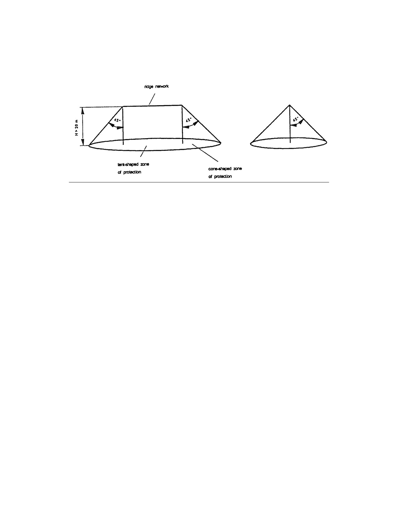
If vertical air termination networks are used, their height and zone of protection shall be such as to ensure that
the entire surface of the building will be situated within this zone of protection (see Figure 3-V). The vertical
air termination networks shall be positioned at least 3 m from the site. In case there should be a barricade, the
vertical air termination networks may be mounted thereupon.
Instead of vertical air termination networks trees may be used and equipped with air termination networks if
they are located in an appropriate position.
c)
In buildings with a complete earth of at least 0.5 m, insulated lightning protection can be omitted; this applies
also to earth covers with vent pipes.
2.3.4.13. Lightning Protection Systems for Buildings
a)
Fixed air termination networks are to be arranged on the building with a mesh size not exceeding 10 m x 10 m.
Parts of the building made of nonconductive material which protrude from the network are to be equipped with
suspended air termination networks and pointed conductors. Superstructures made of metal are to be bonded to
-II-3-13-
Change 3

AASTP-1
(Edition 1)
the suspended air termination networks. The air termination networks of the lightning protection system of the
building must be installed in the middle between the conductors of the insulated lightning protection system
(top view). Each building must have one down conductor for 10 m each of the circumference of the building
with four down conductors being the minimum number. Those down conductors should be positioned at least
0.5 m from windows, doors, and other openings. Aboveground pipelines leading up to the buildings are to be
bonded to the down conductor next to them. In the case of reinforced concrete buildings which have connected
reinforcing rods, these can be used as down conductors; these buildings only require air termination networks
but not separate down conductors. Reinforced concrete buildings without connected reinforcing rods are to be
equipped with air termination networks and down conductors. In any case the reinforcement is to be bonded to
the internal ring conductor at intervals not exceeding 10 m.
b)
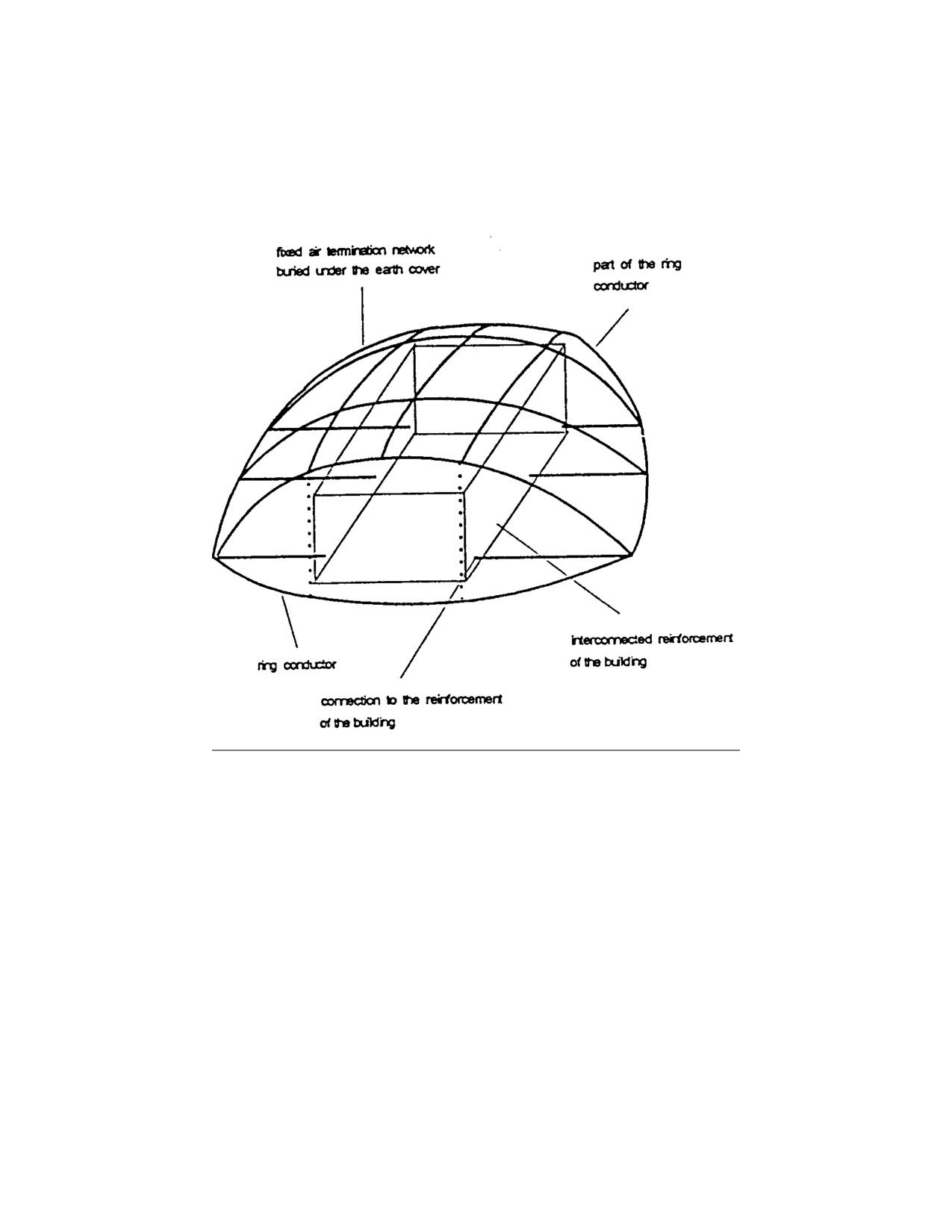
For earth-covered buildings (e.g. igloo) with an earth-cover of at least 0.5 m a fixed air termination network
having a mesh size not exceeding 10 m x 10 m and installed within or on the earth-cover is a sufficient
lightning protection (see Figure 3-VI). For buildings with a lateral length of less than 10 m two conductors in a
diagonal arrangement are sufficient. Those conductors are to be bonded to a ring conductor. Metal venting
systems which protrude from the earth-cover are to be equipped with down conductors which must be bonded
to air termination networks or the ring conductor. Venting systems made of non-conductive material must be
equipped with air termination networks and down conductors. In buildings made of reinforced concrete the
connected reinforcement can be used as down conductor; it must be bonded to the ring conductor in at least
two opposing locations. Suspended air termination networks are necessary here as well. Instead of a fixed air
termination network, a space screen (e.g. as alternative upgrading measure) may be inserted into the building.
The space screen consists of a network of band steel having a mesh size not exceeding 2 m x 4 m on which a
fine grid (5 cm x 10 cm) is installed. The space screen must surround ceilings, walls, and columns; it is to be
connected to the ring conductor.
2.3.4.14. Earth Termination Networks
Each lightning protection system must be grounded with an earth termination network. In most cases closed
ring conductors or grounding circuits are used for that purpose.
-
The total earth resistance of the earth termination network shall not exceed 10 ȍ for buildings or groups of
buildings.
-
The earth termination network and the lightning protection system are to be appropriately connected.
-
Earth termination networks of adjoining buildings within a radius of 20 m are to be connected underground.
-II-3-14-
Change 3

AASTP-1
(Edition 1)
-
Ammunition and packaging containing ammunition are usually not grounded.
-
Test joints are to be integrated into the lightning protection system between down conductor and earth
termination network for test and measuring purposes. They are to be situated approximately 0.5 m above
ground; below the test joint only parts of the earth termination network are permissible.
2.3.4.15. Equipotential Bonding in Lightning Protection
All essential conductive elements of a building such as machines, equipment, radiators, pipelines as well as
large metal items (metal doors and windows, conductive floors) are to be bonded to the lightning protection system via
lines.
2.3.4.16. Lightning Protection Systems for Open-air Stacks of Ammunition
a)
Ammunition stacks endangered by lightning, especially those containing mass-detonating ammunition, are to
be protected by a lightning protection system.
Ammunition stacks are particularly endangered by lightning discharge if they are situated.
-
on mountain tops, hills,
-
at the edges of woods, or
-
under isolated trees.
b)
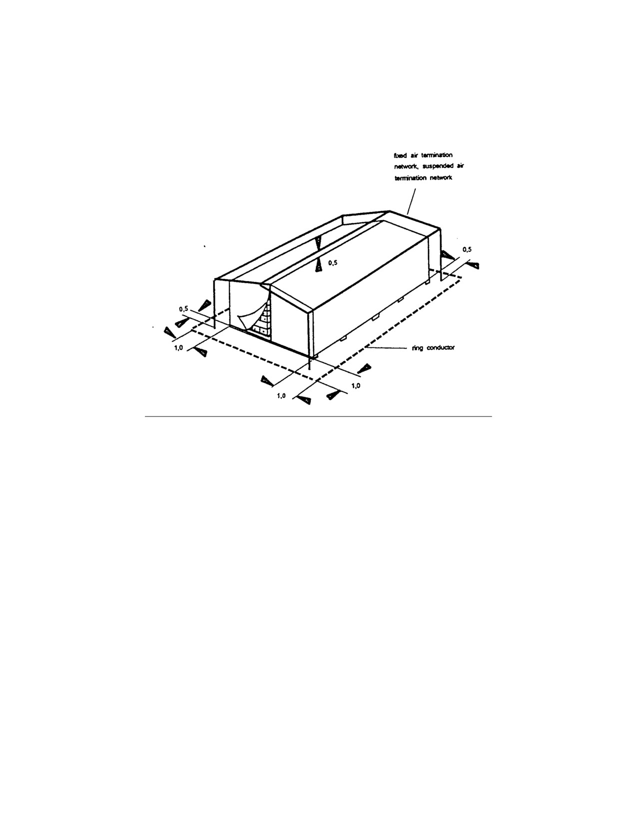
In general, four horizontal aerial conductors of a rectangular shape (e.g. zinc-coated steel rope with a cross
section of 50 mm2 mounted on insulated supports (e.g. made of wood) at least 0.5 m above the upper edges of
the ammunition stack are sufficient to provide lightning protection. On each of the four corners one down
conductor which is to be bonded to the ring conductor shall be installed at least 0.5 m from the stack. The ring
conductor is to be buried at least 0.5 m below ground with a minimum lateral distance of 1 m round the
perimeter of the stack (see Fig 3 - VII). If the stacks are positioned on floor plates the latter are to be connected
with the ring conductor on the four corners of the stack.
c)
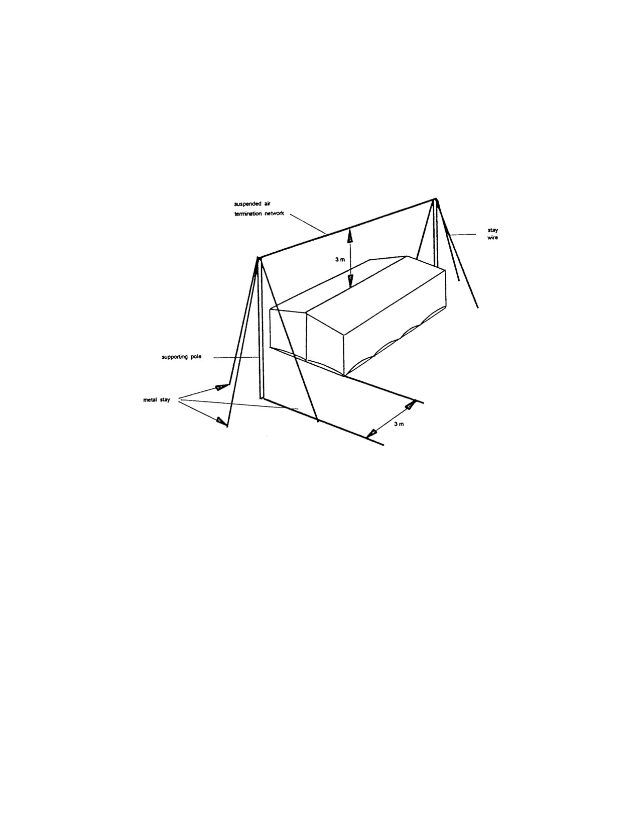
For ammunition stacks established temporarily a makeshift lightning protection is sufficient which is arranged
as follows:
A zinc-coated steel rope of at least 50 mm2 in cross section or a copper rope of at least 35 mm2 in cross section
which is to be supported by 2 supports made of wood or metal is to be tensioned across the stack. Outside the
supports the rope is to be secured in the ground with metal stays.
-II-3-15-
Change 3

AASTP-1
(Edition 1)
Additionally, each support has two stay wires with metal stays. The distance between the rope tensioned across
the stack and the supports to the stack is to be 3 m; in case of deviations it must be ensured that the complete
stack lies within the protected zone (see Fig 3 - V and 3 - VIII).
2.3.4.17. Lightning Protection Systems for Ammunition Bins
a)
In ammunition bins made of concrete the reinforcement forms a conductive cage which is to be grounded using
two earth electrodes (50 cm deep into the ground).
b)
If ammunition bins made of wood are to be equipped with a lightning protection system, they must be provided
with suitable suspended air termination networks and the conductive roof decks are to be included in the
lightning protection system.
2.3.4.18. Minimum Distances of Ammunition from Lightning Protection Systems
Ammunition and packaging containing ammunition are to be stored so as to prevent flash over the lightning
stroke from the lightning protection system to the ammunition or the packaging. Ammunition stacks in a
magazine or an explosives workshop are to be positioned at a distance to walls, support, ceilings, beams, metal
parts, and electrical installations which shall be:
-
10 cm at least if the lightning protection system is properly designed and meets the requirements of
this chapter,
-
50 cm at least if the lightning protection system does not meet the requirements of this chapter.
2.3.4.19
Testing of Lightning Protection Systems
a)
Each lightning protection system is to be tested upon completion. The result shall be recorded. The established
values for the earth resistance are to be used as comparative values for future tests.
The proper condition of the lightning protection system is to be ensured by regular inspections and
measurements.
-II-3-16-
Change 3

AASTP-1
(Edition 1)
Section V - Standard of Internal Lighting in Explosives Storage Buildings
2.3.5.1.
General
In all explosives storage buildings there is a need to identify accurately stocks from markings and to carry out
documentation. This requires a minimum standard of illumination.
2.3.5.2.
Minimum Standard
Where fixed lighting is provided, the minimum acceptable standard for internal lighting in explosives storage
buildings is 75 lux, measured at floor level.
-II-3-17-
Change 3
AASTP-1
(Edition 1)
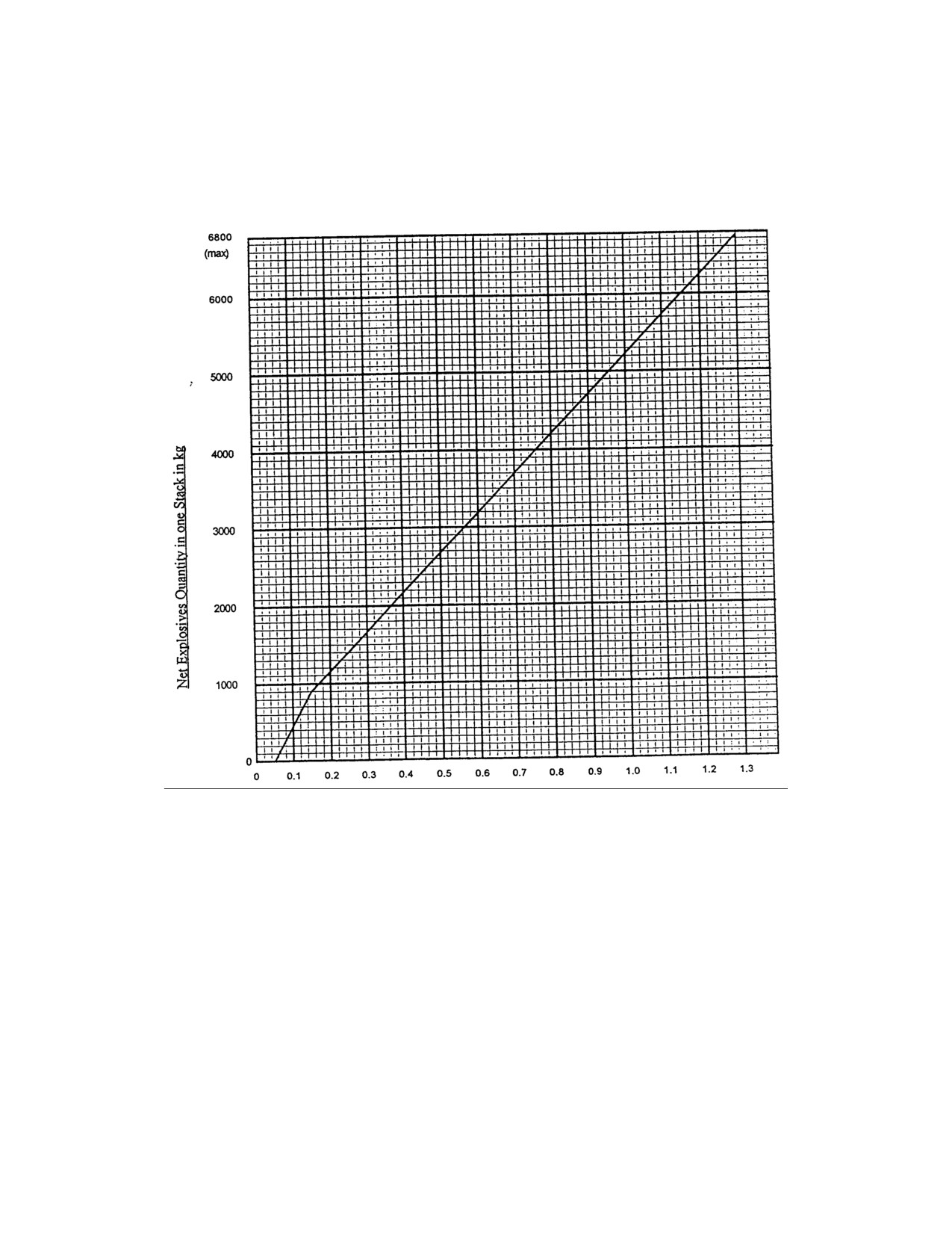
Figure 3 - I Minimum Separation of Adjacent Stack of Certain Projectiles.
Nose-to-Nose or Base-to-Base distances in m
-II-3-18-
Change 3
AASTP-1
(Edition 1)
Figure 3 -II Determination of Barricade Height on Level Terrain
Figure 3 -III Determination of Barricade Height on Sloping Terrain
Figure 3 -IV Determination of Barricade Lenght
-II-3-19-
Change 3
AASTP-1
(Edition 1)
Figure 3 - V Zone of protection of a horizontal suspended air termination network (ridge network)
-II-3-20-
Change 3
AASTP-1
(Edition 1)
Figure 3 - VI
Schematic presentation of an earth-covered magazine with interconnecting reinforced steel
-II-3-21-
Change 3
AASTP-1
(Edition 1)
Figure 3 - VII
Lightning protection system for open stacks of ammunition
-II-3-22-
Change 3
AASTP-1
(Edition 1)
Figure 3 - VIII
Lightning protection system for open stacks of ammunition with an expected short-term deployment (up to one year)
-II-3-23-
Change 3

AASTP-1
(Edition 1)
CHAPTER 4
Reserved
-II-4-1-
Change 3

AASTP-1
(Edition 1)
CHAPTER 5 - DESIGN ENVIRONMENT CRITERIA
Section I - List of Symbols
SYMBOL
DIMENSION
DESCRIPTION
A
(m2)
Area
AT
(m2)
Area of target
A(x)
(m2)
Specifically defined area
Af
(m2)
Projected area of a projectile/fragment
AD
(m2)
Drag area
Av
(g)
Maximum vertical acceleration (shock)
Aw
(m2)
Area of wall
Av , Ah
(m/s2) . (g)
Maximum vertical/horizontal acceleration
a
(m/s2)
Acceleration
ao
(m/s)
Speed of sound
α
(
o)
Angle
B, Bx
(¥kg/m7/6)
Mott constant for explosives
bf
(m)
Fragment width
β
(-)
Pressure drop constant in Friedländer function
CD
(-)
Drag coefficient
CE
(-)
Equivalent load factor
CL
(-)
Confidence level
CP
(m/s)
Seismic velocity in the ground
D
(m)
Distance
D
(m)
Blast wave position at maximum loading of
structural element
D
(kg/m3)
Density/caliber density
D
(N)
Attenuation force
DIF
(-)
Dynamic increase factor
DLF
(-)
Dynamic load factor
Da, Dt
(m)
Depth of apparent/true crater
Dv, Dh
(m)
Maximum vertical/horizontal displacement
D/L
(-)
Blast wave position factor
DOB
(m)
Depth of burst
d
(s)
Duration
di
(m)
Mean inner diameter of ammunition case
E
(J)
Energy
E, Ec, Em, Es
(Pa)
Modula of elasticity for concrete, masonry, steel
Ekin
(J)
Kinetic energy
Ecr
(J)
Critical energy
ES
(-)
Exposed site
F
(N)
Force
FD
(N)
Drag force
F
(Hz)
Frequency
fr
(-)
Reflection factor
F1
(kg/m3)
Ammunition storage building density factor
G
¥(2·E)
Gurney constant
-II-5-1-
Change 3

AASTP-1
(Edition 1)
SYMBOL
DIMENSION
DESCRIPTION
GOF
Terrain surface
g
(9.81 m/s2)
Gravity acceleration
H
(m)
Height
Hs
(m)
Height of building
Hw
(m)
(Height of wall
HOB
Height of burst
I
(Ns)
Shock impulse
I
(m4)
Moment of inertia
Is
(Pa-s)
Positive side-on impulse
Ir
(Pa-s)
Normally reflected positive impulse
Iq
(Pa-s)
Dynamic impulse
ig
(Pa-s)
Gas impulse
is
(Pa-s/kg1/3)
Scaled positive side-on impulse
ir
(Pa-s/kg1/3)
Scaled positive reflected impulse
k
(-)
Shape factor/ballistic density factor
L
(m)
Span of structural element under consideration
L
(m)
Length of flight path traveled after which the
fragment trajectory velocity drops to the (1/e)th part
of the fragment departure velocity
L^
(m/kg)
L related to the unity mass
LH, LL
(m)
Span in transverse/longitudinal direction
Lw
(m)
Blast wave length, positive phase
LS
(m)
Width of structural element strip
Lw/L
(-)
Ratio between blast wave length and span of the
structural element under consideration
ld
(m)
Length of debris (average value of sphere and cube)
M
(kg)
Mass
M
(kg)
Static/dynamic system mass
M
(Nm)
Moment
MA
(-)
Fragment distribution factor
Me
(kg)
Effective mass
Mej
(kg)
Crater ejecta mass
Mex
(kg)
Explosive mass
Mc
(kg)
Total mass of ammunition case
Md
(kg)
Design fragment mass
Mf
(kg)
Mass of the fragment under consideration
Mo
(kg)
Average fragment mass
Mp
(kg)
Projectile mass
Mstr
(kg)
Mass of structure/structural component
Mt
(kg)
Total fragment mass
max
(-)
Maximum
min
(-)
Minimum
N
(-)
Geometrical constant
Nf
(-)
Number of fragments with masses higher than Mf
Nt
(-)
Total number of fragments
Nd
(-)
Number of fragments with masses higher than Md
NEQ
(kg)
Net explosives quantity
NEQTNT
(kg)
Net explosives quantity; TNT equivalent
-II-5-2-
Change 3

AASTP-1
(Edition 1)
SYMBOL
DIMENSION
DESCRIPTION
PES
(-)
Potential explosion site
Po
(Pa)
Peak overpressure
Pso
(Pa)
Peak side-on overpressure
Ps
(Pa)
Side-on overpressure
Pa
(Pa)
Atmospheric pressure; ambient pressure
Pa,s
(Pa)
Atmospheric pressure at standard sea level
Pr
(Pa)
Peak reflected overpressure
P
(Pa)
Pressure
P(t)
(Pa)
Time-Dependent pressure
Pi
(Pa)
Pressure inside of building
P
(%)
Probability
Q, Qexp
(kg)
Charge mass
QTNT
(kg)
Equivalent TNT charge mass
Qo
(kg)
Reference charge, usually expressed at TNT
equivalent
Qo
(-)
Total number of fragments per unit solid angle
emitted in target direction by ammunition item
Qx
(kg)
Actual charge mass, usually expressed as TNT
equivalent
q
(Pa)
Dynamic pressure
qo
(Pa)
Peak dynamic overpressure
q
(kW/m2)
Thermal radiation flux/radiation density
qf
(1/m2)
Fragment density
R
(m)
Separation/radius/distance
Ra, Rt
(m)
Radius of apparent / true crater
Re
(m)
Effective projection distance
Rf
(m)
Fragment distance
RG
(m)
Ground distance
Rm
(N)
Maximum resistance of system
Ro
(m)
Reference distance from center of charge Qo, for a
defined overpressure or dynamic pressure
Rx
(m)
Distance from center of charge Qx (kg) at which the
explosion of the charge Qx produces the same
pressure as that caused by the reference explosion
with the parameters Ro and Qo
r
(Pa)
Unit resistance
rho
(kg/m3)
Soil density
rho
(kg/m3)
Air density
S
(-)
Position index/center of element strip
SGZ
Surface ground zero (point of burst)
TAG
(s)
Arrival time of ground shock wave
To, to
(s)
Duration of positive air blast phase
tof
(s)
Fictitious duration of positive airblast phase
Ta, ta
(s)
Arrival time of shock front
Ta
(
oC)
Ambient temperature
Ta,s
(
oC)
Ambient temperature at standard sea level
Tc, tc
(s)
Clearing time of blast wave at target
To
(K)
Temperature
-II-5-3-
Change 3

AASTP-1
(Edition 1)
SYMBOL
DIMENSION
DESCRIPTION
Tr, tr
(s)
Time of load increase
t
(s)
Time
tw
(s)
Duration of loading
ta,a
(s)
Arrival time of blast wave
ta,s
(s)
Arrival time of direct ground shock wave
tc
(m)
Mean thickness of ammunition case
tc
(s)
Clearing time
ts
(s)
Time at point of intersection between reflected
pressure and combined side-on / drag pressure
tr
(s)
Duration of reflected pressure
U
(m/s)
Shock front velocity
u
(m/s)
Particle velocity behind shock front
Va, Vt
(m3)
Volume of apparent/true crater
V
(m/s)
Velocity
Vcr
(m/s)
Critical velocity
Vf
(m/s)
Final velocity of projections
Vm
(m/s)
Mean impact velocity
Vo
(m/s)
Departure/initial velocity
Vr
(m/s)
Residual velocity
Vs, Vi
(m/s)
Impact velocity
Vv, Vh
(m/s)
Maximal vertical/horizontal velocity
W
(N)
Weight
W
(J)
Work
Wf
(N)
Fragment weight (mass)
Ws
(m)
Width of structure
X, x
(m)
Deformation
x
(-)
Position index
Xel, Xp
(m)
Elastic/plastic deformation
Yel
(m)
Elastic deformation of system
Ym, Yp
(m)
Plastic deformation of system
Z
(m/kg1/3)
Scaled distance
ZA
(m/kg1/3)
Scaled normal distance
ZG
(m/kg1/3)
Scaled distance above ground
-II-5-4-
Change 3

AASTP-1
(Edition 1)
Section II - General
2.5.1.1
Introduction
This chapter deals with the effects of an accidental explosion or fire in an aboveground ammunition storage
site on persons or surrounding buildings and other engineering works. The magnitude of the effects constitute the
design environment criteria.
2.5.1.2
General Principles
Design Environment Criteria
The design environment criteria serve the purpose of …
-
. . . preparing risk analyses;
-
. . . designing and dimensioning ammunition storage facilities;
-
. . . defining quantity distances;
-
. . . determining hazard parameters in terms of quality and quantity;
Note:
The quantity distances are based on design environment criteria, threat spectrum as well as performance and
safety requirements.
-
. . . verifying design drawings and detail specifications for facilities of a particular site in
order to assure compliance with the safety regulations;
-
. . . modifying buildings originally constructed for other purposes to ammunition storage
buildings and explosives workshops;
-
. . . planning damage control, fire-fighting and rescue operations.
Basic Data
There is further basic research to be done in order to complete the technological basis required for exploiting
all conceivable uses of explosives and ammunition storage buildings. The technological developments with
respect to ammunition types, building materials as well as design and dimensioning make it necessary to
constantly improve the relevant data and knowledge base. For the economical handling of the problem fields,
special data banks with constant updating are required. Carefully prepared scaled model and full-scale tests
will provide these data, constitute the basis for realistic risk analyses and help saving costs.
2.5.1.3
General Design Aspects
Design Principles
To ensure compliance with the safety requirements for exposed sites, the design methods applied must be
selected according to the following basic conditions.
-II-5-5-
Change 3

AASTP-1
(Edition 1)
(1)
No Design Environment Criteria Available (Standardized Construction)
When no design environment and performance criteria are given, the building shall conform to a
standard construction which, in former explosion events, has proved to be satisfactory for a given
Net Explosives Quantity (NEQ) at a specific distance or has been proof-tested, preferably in full-
scale tests.
With this approach, additional design calculations are not required, and deviations from applicable
construction specifications and quantity distance requirements are not permitted since the
consequences are not predictable.
Note:
This method is inflexible and does no longer constitute a state-of-the-art approach.
(2)
Limited Design Environment Criteria Available
In case only a few quantity distance values are available as design environment criteria, design and
construction will be based on analytical calculations supported by model or full-scale tests. The
construction may be safely used over the full range proved by the calculations. Appropriate
consideration of design criteria (e.g. specified quantity distance) provided, modifications to the
original construction are permissible since consequences of such modifications can be predicted to a
large extent.
Note:
This method constitutes a compromise between empirical and analytical approaches.
(3)
Complete Design Environment Criteria Available
When design environment criteria are available as continuous functions of net explosives quantity
and distance from the Potential Explosion Site (PES), there is complete freedom to choose both the
distance and the type of construction in order to obtain the most economical solution. Design and
construction are based on analytical calculations supported by model or full-scale tests. The
construction may be used over the full range proved by the calculations. Modifications may be made
provided the design environment criteria are taken into account.
Note:
This is the ideal case giving complete freedom with respect to design and modifications.
When seeking the optimum combination of construction type, required quantity distance, and degree
of protection, the following parameters shall be taken into account:
-
Availability of land for building purposes;
-
Costs of land;
-
Construction costs;
-
Value of ammunition and explosives stored in the Exposed Site (ES) which would become
unserviceable in case of an explosion in the potential explosion site.
For ammunition storage facilities exceeding the minimum strength and blast resistance requirements the
quantity distances may be reduced provided qualified evidence has been furnished.
When designing a building for the storage of ammunition, in almost all cases the donor/acceptor
conflict has to be solved.
-
A building with donor function should be of lightweight in order to minimize the size and
mass of projections.
-II-5-6-
Change 3

AASTP-1
(Edition 1)
-
A building with acceptor function must have a relatively high strength in order to avoid
sympathetic detonation due to airblast, projections, shock or collapse of buildings
Degrees of Protection
As it is uneconomical to use a building for only one hazard division, it is common practice to store ammunition
of different hazard divisions in one storage facility.
The degrees of protection define the expected or required extent of protection against the effects of an
accidental explosion for each hazard division.
-II-5-7-
Change 3

AASTP-1
(Edition 1)
The degrees of protection are distinguished as follows
Degrees of
Hazard
Protection Criteria Remarks
Protection
Division
Virtually
1.1
-
Against:
Practically instantaneous propagation of explosion by
Complete
ground shock, blast, flame and high velocity projections.
Protection
-
Result:
-
Immediate sympathetic detonation not to be
expected.
-
Stored items largely remain serviceable.
-
Individual evaluation required for sensitive
stored items.
1.2
-
Against:
Immediate or subsequent fires and explosion caused by
blast, flame, firebrands protections and lobbed
ammunition.
-
Result:
-
Immediate or delayed sympathetic detonation not
to be expected.
-
Stored items probably remain serviceable.
1.3
-
Against:
Immediate or subsequent fires among the contents of an
ES by flame, radiant heat, firebrands, projections and
lobbed ammunition.
-
Result:
-
Immediate or delayed burning, deflagration or
explosion of stored items not to be expected.
-
Inflammation of burnable external parts of the
building.
-
No propagation of fire to stored items.
Degrees of
Hazard
Protection Criteria Remarks
Protection
Division
High Degree
1.1
-
Against:
Practically instantaneous propagation of explosion by
of Protection
ground shock, blast, flame and high velocity projections.
-
Result:
-
High protection against immediate sympathetic
detonation.
-
Delayed fire and sympathetic detonation to be
expected.
-
Bulk of stored items probably remains
serviceable.
1.2
-
Against:
Immediate propagation of explosion by blast, flame and
projections.
-
Result:
-
High protection against immediate sympathetic
detonation.
-
Delayed fire and sympathetic detonation to be
expected.
-
Loss of stored items depends on effectiveness of
fire fighting.
1.3
-
Against:
Immediate propagation of fire to the contents of as ES by
flame, radiant heat, firebrands, projections and lobbed
ammunition.
-
Result:
-
Delayed burning, deflagration or explosion of
stored items cannot be excluded.
-
Inflammation of burnable internal and external
parts of the building.
-
Stored items may catch fire.
-II-5-8-
Change 3

AASTP-1
(Edition 1)
Degrees of
Hazard
Protection Criteria Remarks
Protection
Division
Limited
1.1
-
Against: Practically instantaneous propagation of explosion by
Degree of
ground shock, flame and high velocity projections.
Protection
-
Result:
-
Immediate sympathetic detonation to be
expected.
-
Stored items severely damaged and
unserviceable.
1.2
-
Against: Immediate or subsequent fires among the contents of an
ES by flame, radiant heat, firebrands, projections and
lobbed ammunition.
-
Result:
-
Limited protection against immediate
sympathetic detonation.
-
Fire and sympathetic detonation to be expected.
-
Loss of stored items in case of ineffective fire
fighting.
Due to the high costs involved, virtually complete protection will only be reasonable, if the net explosives
quantity is small or if the total quantity of the items stored inside the building is divided by walls into smaller
portions thus avoiding immediate sympathetic detonation.
Protection Against Sympathetic Detonation
Ammunition storage buildings shall be designed in such a way as to reliably prevent sympathetic detonation of
stored explosives.
Thus, the primary design objective must be to prevent destruction or collapse of the building.
Plastic deformation of structural parts shall be acceptable as long as the stability of the building is not
impaired. Deformation, however, shall be less than the separation distance between the deformed part
and the stored items so that no shock propagation is possible.
Proper design of the exposed site and adequate quantity distance from the potential explosion site are essential
factors to prevent immediate sympathetic detonation which may be initiated by high-energy projections,
spalling, torn-off structural parts (e.g. pillars, doors etc.), or by the collapse of the building.
Degree of hazard, type of stored items, design, and environment of the ammunition storage facility are critical
parameters for the evaluation of the sympathetic detonation load case.
It is impossible to specify quantity distances which provide complete safety from sympathetic detonation,
damage or injury. Economical and internal operational reasons may temporarily justify a calculated risk to
personnel and material. It also may be necessary under certain circumstances to deviate from regulations due to
tactical requirements. Design measures should be taken to prevent spalling inside the building. This applies
primarily to buildings which are not earth-covered. Tests have demonstrated that spalling velocities are usually
overestimated except when caused by contact detonations. Dangerous spalling effects are not to be expected
with earth-covered buildings.
Lobbed ammunition may explode upon impact. The explosion of ammunition with a caliber of more than 155
mm impacting close to the wall or on the roof of an exposed storage building may cause a sympathetic
detonation.
Ammunition storage buildings shall provide full protection against projections of any kind, such as fragments,
structural debris, lobbed ammunition and spalling. The limits for spalling, below which no firing of packaged
initiating devices will be caused, are specified in AASTP-1, 2.3.3.2.
According to this paragraph, for the different spalling velocities the following criteria shall apply
-II-5-9-
Change 3

AASTP-1
(Edition 1)
(-->> Table [5.27]) . . .
For velocities ≥ 50 m/s the kinetic energy shall be Ekin ≤ 2500 Js
For velocities ≤ 50 m/s the impulse
shall be I ≤ 100 Ns
Penetration by projections shall only be acceptable if the residual velocity (Vr) of the penetrating projectile is
below the critical velocity (Vcr) at which sympathetic detonation is induced.
For Vr ≤ 50 m/s
Vcr
=
100 / Mp
(m/s)
For Vr ≥ 50 m/s
Vcr
=
¥ (5000/Mp)
(m/s)
Loads / Design Loads
As a rule, ammunition storage buildings should be individually designed according to local design
environment criteria. Existing design formulations and data will allow the sufficiently safe determination of the
various loads to be expected.
An accidental explosion or fire in an aboveground ammunition storage site constitutes a hazard to personnel,
buildings, facilities, and other material due to airblast, fragments, structural debris, shock and thermal
radiation. These effects, which occur almost simultaneously, define the design environment criteria for
planning and designing ammunition storage buildings. The design loads for an exposed building or structural
part of a building are functions of these effects as well as of geometrical and material conditions at the exposed
site.
(1)
Rebound of Closure Components
An airblast acting on closures, such as doors and gates, will produce extreme rebound loads on the
latches and hinges. In order to ensure security of building closures, the ability of the construction to
withstand these rebound loads must be mathematically proven.
The parameters of a blast wave due to an accidental explosion depend upon the complex conditions at the
explosion site.
These include:
-
Distribution of explosives at the storage site;
-
Loading density;
-
Types of explosives;
-
Explosives content of the stored ammunition;
-
Mass and type of earth cover and building;
-
Constructional stability of the building.
Design Details
(1)
Aboveground Ammunition Storage Buildings
For a storage site with earth-covered or detached uncovered aboveground ammunition storage
facilities (e.g. igloos), the most straightforward and safe quantity distances will result if the storage
-II-5-10-
Change 3

AASTP-1
(Edition 1)
area has a rectangular shape, the axes of the ammunition storage buildings are parallel to each other,
and all doors face in the same direction.
An arrangement with the front walls of the buildings facing each other should be avoided for
economical (area required) and safety reasons.
Due to its type of design, an earth-covered ammunition storage building (igloo type) will effectively
withstand external effects such as airblast, fragments, and exploding lobbed ammunition, provide
protection of the stored items and prevent sympathetic detonation.
(2)
Ammunition Stacks
Exploding ammunition stacks in the open or inside storage buildings may produce highly effective
projections, such as fragments, structural debris, and lobbed ammunition, which may penetrate into
a storage facility and immediately ignite the stored explosives and ammunition. Ceilings, doors, and
closures must be designed in such a way as to intercept projections of any kind or reduce their
velocity to a safe residual value. As an additional safety measure, barricades may be retrofitted,
which, however, will provide no protection against projections from above.
(-->> AASTP-1, 1.4.6.1. to 1.4.6.10.)
(3)
Walls
The minimum thickness required for wall and ceiling slabs affording adequate protection against
fragments, structural debris, detonating lobbed ammunition and firebrand, will depend upon the type
of the stored ammunition.
Table
[5-1] contains reference values for various construction materials related to selected
ammunition types.
(-->> Ref [1], [2])
(4)
Roofs and Ceilings
Roofs and ceilings may be designed such as to perform the following functions:
-
Contain fragments and prevent emission of projections.
-
Provide shielding against airblast, projections, and lobbed ammunition.
(5)
Pressure Relief Walls
An explosion in an asymmetrical ammunition storage building with a weak wall or roof (frangible
cover) will produce directed effects (airblast, flames, projections).
Pressure relief walls
(frangible covers) as well as doors and other closures shall be designed
fragment-proof and debris-proof. With standard earth covers, there will be no problems except in
case of a contact hit.
In case of not earth-covered ammunition storage buildings, the conflict between pressure relief and
fragment resistance requirements has to be solved. These requirements lead to contrary design
solutions. An approach to this problem is the erection of barricades to shield the pressure relief
component against fragments and debris.
(-->> AASTP-1, 2.3.2 and 2.3.3)
(6)
External Walls
Experience has shown that for not earth-covered buildings two-leaf external walls provide a high
degree of protection against airblast, fragments and debris. The outer leaf which is considerably
thinner must be separated from the inner main leaf by an air gap of approximately 0.10 m. The outer
-II-5-11-
Change 3

AASTP-1
(Edition 1)
leaf, which serves to absorb the airblast, should consist of lightly reinforced concrete or masonry
with a thickness of at least 0.10 m.
(-->> AASTP-1, 2.3.3.)
(7)
Internal Walls and Dividing Walls
Structures required to contain fragments, debris and lobbed ammunition necessitate a more
sophisticated design than dividing walls to prevent sympathetic detonation. A double-leaf
construction should always be taken into consideration.
(8)
Doors and Gates
Doors and gates constitute weak points in terms of safety. As they have to be relatively large and
must be movable in addition, their design tends to become very complex to ensure adequate
resistance to explosion effects.
Doors and gates should be single-piece structures.
If a door is not part of a so-designed structural weak wall (frangible cover), it shall resist the airblast
to be expected and be fragment-proof and debris-proof.
The following essential criteria shall be considered for the design of doors . . .
-
Dynamic design with respect to airblast loading;
-
Assessment of rebound loads and appropriate design of door hinges and latches;
-
Proof of resistance to fragments;
-
Proof of resistance to high impulse loads due to impact of debris;
-
Ease of use.
(9)
Barricades
Barricades are structures suitable to intercept directed projections and to a limited extent to constrain
the effects of airblast and flames.
Above all, barricades reduce the effects of fragments and other projections ejected out of openings.
Note:
-
Efficiency of protection and employment range of barricades are described in detail in
AASTP-1, 1.4.6.
-
Details on the design of effective barricades are given in AASTP-1, 2.3.3.
An earth-covered building may be considered equivalent to a building with barricades if, for
example, the thickness and slope of the earth cover comply with the requirements of AASTP-1,
1.4.6, or meet the other criteria stated there.
Natural terrain features, such as wood, elevations, soil etc., may be regarded as "natural barricades"
if they have proven to provide the required protection. It must be considered, however, that the
natural environment and thus the protection it provides may change in the course of time.
(10)
Ventilation
When designing the ventilation system, preference should be given to natural ventilation for
economical reasons. The ventilation system must be designed such as to prevent ingression of
airblast, primary and secondary projections as well as thermal radiation and flames or reduce their
effects to a safe level.
-II-5-12-
Change 3

AASTP-1
(Edition 1)
Construction Materials for Ammunition Storage Buildings
Basically, fire-resistant or at least fire-retardant materials should be used.
Typical materials for the construction of aboveground ammunition storage buildings are concrete, reinforced
concrete, masonry, corrugated steel liners or steel arches. In addition, soil material with a special consistency is
normally used for the earth covers.
Exposed parts made of iron, steel, aluminum or aluminum alloys, which might come into contact with
explosives, shall not contain more than 1 % of magnesium.
The walls and floors of rooms intended for the storage of chemical agents shall be lined with chemical agent-
repellent material at least up to the height of the stacks. Adequate ventilation of the storage area shall be
ensured.
2.5.1.4
References
Essential references -->> Section VIII
Ref
[1], [2], [3], [4], [76], [77], [78], [79], [83], [89], [102]
-II-5-13-
Change 3