Robinson R22 Helicopter. MAINTENANCE MANUAL (2018) - page 2
5.200 Cross Tubes
5.210 Cross Tube Removal
Replace cross tube(s) if yielding results in tail skid-to-level ground dimension of less than
24 inches for a Standard or HP, 34 inches for an Alpha/Beta/Beta II, or 37 inches for a
Mariner/Mariner II with float stabilizer installed.
NOTE
See § 2.550 for hard landing inspection criteria.
1. Remove landing gear per § 5.110.
2. Using a soft brass or aluminum drift, carefully tap out spacers securing cross tube in
strut elbow and tap elbows off cross tube.
3. If difficulty is encountered removing strut elbow from cross tube:
a. Install spacer securing opposite strut elbow to cross tube.
b. Disconnect stuck strut assembly from skid tube.
c. Place a rigid support under cross tube.
d. Using strut on stuck elbow as handle, rotate elbow on cross tube to break paint
bond.
e. Remove spacer installed in step a. and remove cross tube.
OCT 2018
Chapter 5 Landing Gear
Page 5.3
5.220 Cross Tube Installation
1. Install cross tube in upper strut elbow. Place a wooden block against end of cross
tube and tap as necessary to align mounting hole in cross tube with hole in elbow.
2. Install spacers by tapping them through elbows and cross tubes with a soft face
hammer.
5.300 Skid Tubes
5.310 Skid Tube Removal
Replace skid tubes worn beyond 0.030-inch maximum depth (no length limit) longitudinal
scratch, 0.030-inch maximum depth and 0.50-inch maximum length circumferential
scratch, or 0.50-inch maximum width flat spot.
1. Raise one side of helicopter by jacking under one end of the aft cross tube, one inch
inboard of fitting.
2. Remove 4 bolts at each landing gear strut. Remove skid tube.
5.320 Skid Tube Installation
Place skid tube under fore and aft gear struts and install attach bolts. Standard torque
attach bolts per § 23-32 (self-locking nutplate installed inside skid tube).
5.330 Skid Shoe Removal and Replacement
NOTE
Replace A667-5 and -6 skid shoes less than 0.050 inch thick.
1. Install ground handling wheels.
2. Push down on tail and place a wooden block approximately 4 inches ahead of
intermediate skid shoes. (See Figure 5-3.)
3. Remove bolts attaching forward and intermediate shoes to skids. Discard worn shoes
and screws.
4. Install new skid shoes and screws. Standard torque screws per § 23-32.
NOTE
Some early R22’s had forward skid shoes attached using
aluminum blind rivets (MS20600AD6-4). These can be removed
by drilling off head and punching out shank.
Page 5.4
Chapter 5 Landing Gear
OCT 2018
CHAPTER 6
POWERPLANT
Section Title
Page
6.000
Powerplant And Related Systems
6.1
6.001
Introduction
6.1
6.002
Description
6.1
6.100
Powerplant
6.2
6.110
Engine Removal
6.2
6.120
Engine Installation
6.2
6.130
Engine Shimming
6.6
6.200
Cooling System
6.9
6.210
Fanwheel Removal
6.9
6.220
Fanwheel Installation
6.12
6.230
(Reserved)
6.240
Balancing Fanwheel
6.13
6.250
Cooling Scroll Replacement
6.16A
6.300
Lubrication System
6.18
6.310
Oil Cooler Removal
6.18
6.320
Oil Cooler Installation
6.18
6.400
Induction System
6.18
6.410
Carburetor Removal
6.18
6.420
Air Box Removal
6.19
6.430
Air Box Installation
6.19
6.435
Air Filter Cleaning
6.21
6.440
Carburetor Installation
6.21
6.450
Carburetor Heat Scoop Removal
6.22
6.460
Carburetor Heat Scoop Installation
6.22
6.500
Exhaust System
6.22
6.510
Exhaust System Removal
6.22
6.520
Exhaust System Installation
6.22
6.600
Troubleshooting
6.23
6.610
Low-Power Checklist
6.23
6.700
Throttle Control And Carburetor Heat Assist
6.25
6.710
Overtravel Spring
6.25
6.711
Overtravel Spring Removal
6.25
6.712
Overtravel Spring Installation
6.25
6.720
(Reserved)
OCT 2014
Chapter 6 Powerplant
Page 6.i
CHAPTER 6
POWERPLANT (Continued)
Section Title
Page
6.730
Throttle Push-Pull Tube Assembly
6.26
6.731
Throttle Push-Pull Tube Assembly Removal
6.26
6.732
Throttle Push-Pull Tube Assembly Installation
6.26
6.740
Carburetor Heat Assist
6.26
6.741
Carburetor Heat Control Cable Removal
6.26
6.742
Carburetor Heat Control Cable Installation
6.27
6.743
D334-5 Carburetor Heat Assist Bellcrank Removal
6.27
6.744
D334-5 Carburetor Heat Assist Bellcrank Installation
6.27
6.745
D334-5 Bellcrank Friction Adjustment
6.29
Page 6.ii
Chapter 6 Powerplant
OCT 2014
CHAPTER 6
POWERPLANT
6.000 Powerplant and Related Systems
6.001 Introduction
This section includes instructions for removal and installation of engine and support
systems. Support systems include induction, cooling and exhaust systems. Refer to
engine and engine component manufacturer’s maintenance publications for product
specific inspection, repair, and maintenance procedures.
6.002 Description
R22-series helicopters are powered by one of four different Lycoming engines. O-320-
A2B or O-320-A2C engines are installed in standard model R22s and are normally rated
at 150 horsepower. O-320-B2C engines are installed in R22 HP, R22 Alpha, and R22
Beta models and are normally rated at 160 horsepower. Beta II/Mariner II helicopters
have an O-360-J2A engine capable of 180 horsepower, derated by Lycoming to 145
horsepower. All engines are derated to 124 maximum continuous horsepower (MCP) by
limitation of manifold pressure and RPM. Beta, Mariner, and Beta II/Mariner II helicopters
have a 5-minute takeoff rating of 131 HP (see Pilot’s Operating Handbook). Starting
assist for O-320-A2B engines is provided by an impulse coupling installed on the engine-
left (helicopter-right) magneto. Starting assist for O-320-A2C, O-320-B2C, and O-360-
J2A engines is provided by a starter vibrator system and retard points in the engine-left
magneto. Tachometer points in the engine-right magneto supply engine RPM information
to the governor controller and engine tachometer. At 104% engine tachometer indication
the engine is turning 2652 RPM.
Induction is through an air filter located in a carburetor-mounted air box assembly.
Carburetor heat is supplied by an exhaust-pipe-mounted scoop and duct. Carburetor heat
is controlled through a cable-operated guillotine valve in air box. Carburetor inlet air is
filtered, even with carburetor heat on. Provision for an obstructed air filter is provided
by a spring loaded bypass valve mounted on the air box cover, or by air box flexing. On
Beta II/Mariner II aircraft, application of carburetor heat is correlated with changes in
collective setting through a friction clutch to reduce pilot work load. Lowering collective
mechanically adds carburetor heat and raising collective reduces carburetor heat. The
pilot may override the friction clutch and increase or decrease carburetor heat as desired.
A latch is provided at the carburetor heat control knob to lock carburetor heat off when
not required.
Cooling is supplied by an engine-mounted fanwheel enclosed by a fiberglass scroll. The
scroll ducts cooling air to engine-mounted panels which in turn direct air to cylinders,
external oil cooler, alternator, and main rotor gearbox.
Power is transmitted through a vertically mounted sheave-and-belt system which is
engaged by an electric belt tension actuator.
Battery charging and electrical power is supplied by 60-amp belt-driven alternator. A 70-
amp alternator is optional.
OCT 2014
Chapter 6 Powerplant
Page 6.1
6.100 Powerplant
NOTE
Refer to engine and engine component manufacturer mainte-
nance publications for product specific inspection, repair, and
maintenance procedures.
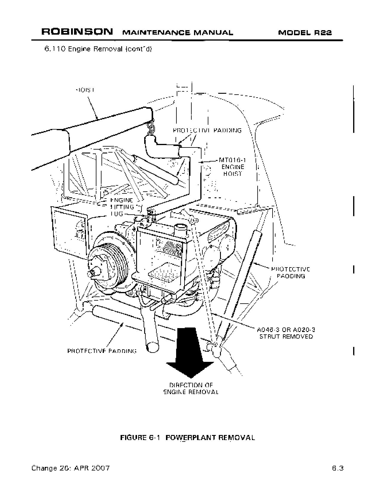
6.110 Engine Removal
NOTE
If engine is to be removed to facilitate a lower frame replacement,
engine mount change, or firewall repair, fanwheel can remain
installed. However, if engine is to be disassembled, remove
fanwheel per § 6.210.
1.
Disconnect static line from and remove aft cowling, tailcone fairing, B429-5 frame.
NOTE
If aux tank installed, defuel helicopter. Remove aux tank.
2.
Disconnect main rotor gearbox cooling duct and remove horizontal firewall access
panel (aft right-hand).
3.
Remove clutch assembly per § 7.210.
4.
Remove side skirts. Turn off fuel selector valve and disconnect fuel hose at carburetor.
Cap fuel hose and carburetor inlet port.
5.
Disconnect carburetor throttle linkage at carburetor bellcrank, mixture control cable
at carburetor, carburetor heat control at air box, and carburetor air temperature probe
at quick-disconnect, located approximately four inches from probe in a heat shrink
sleeve. Remove carburetor and air box assembly.
NOTE
Air box and carburetor may be removed as a unit.
6.
Disconnect oil pressure hose from elbow on accessory housing and cap exposed
connections.
7.
Disconnect manifold pressure line from forward, left cylinder fitting and clamp and cap
exposed connections.
8.
Identify for reinstallation and disconnect engine ground straps, alternator leads,
starter leads, oil pressure line, cylinder head temperature lead, and oil temperature
lead. Disconnect all clamps attaching wiring to steel tubular frames. Disconnect belt
tension actuator motor leads.
9.
Disconnect cabin heater duct, if installed (optional equipment).
10.
Disconnect primer line, if installed (optional equipment).
Page 6.2
Chapter 6 Powerplant
OCT 2014
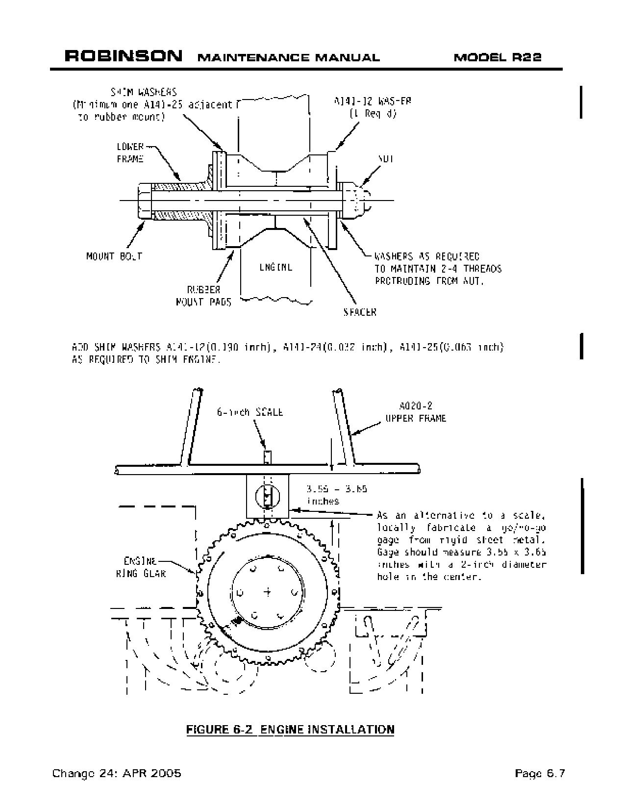
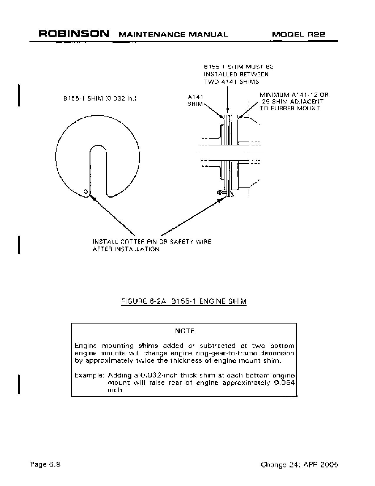
6.130 Engine Shimming (continued)
NOTE
AN6- engine mount bolts are obsolete and must be replaced with
NAS1306- or NAS6606- series bolts when shimming engine.
11. Check clutch sheave alignment per § 7.230.
12. Reinstall engine inspection covers and side skirts.
13. Adjust throttle correlation rigging per § 10.150.
6.200 Cooling System
6.210 Fanwheel Removal
CAUTION
Do not engage actuator without scroll installed.
NOTE
If same fanwheel is to be reinstalled then orient starter ring gear
support to magneto timing position and mark fanwheel at split
line of scroll; this will minimize need for new balance weights.
See Figure 6-3B.
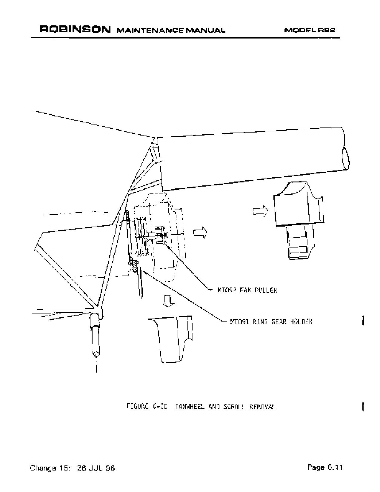
a) Remove fiberglass scroll-to-engine cooling panel perimeter screws and two bolts
attaching lower scroll to lower actuator bearing block. Scroll lower half may be
removed from scroll upper half at this time if desired.
b) Remove safety wire and roll pin from fanwheel retaining nut. Refer to Figure 6-3B.
Secure MT091-1 engine ring gear holding tool to ring gear support and hold ring gear
stationary. Remove fanwheel retaining nut.
CAUTION
Failure to secure MT091-1 tool to ring gear support may result
in damage to support.
OCT 2018
Chapter 6 Powerplant
Page 6.9
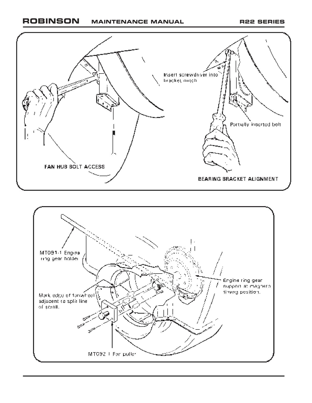
FIGURE 6-3A FAN HUB ACCESS AND LOWER BEARING BRACKET ALIGNMENT
FIGURE 6-3B PULLING FANWHEEL
Page 6.10
Chapter 6 Powerplant
OCT 2018
6.435 Air Filter Cleaning
NOTE
Replace B771-1 air filters after 5 years or 600 flight hours,
whichever occurs first.
1.
Remove B771-1 air filter from airbox. Visually inspect filter and verify no obvious
damage. Inspect filter’s pleated media for cleanliness. If the media contains only
dust, clean media using compressed air or water. Clean heavily soiled media using
a mild soap & water solution.
a. Compressed air: Maintain at least one-inch distance between air nozzle and
pleated media and apply less than 40 psi compressed air thru media opposite
the normal direction of airflow.
b. Water: Apply less than 40 psi water stream thru media opposite the normal
direction of airflow. Dry filter thoroughly using less than 160°F warm air.
c. Mild soap & water solution: Apply less than 40 psi water stream thru media
opposite the normal direction of airflow. Soak filter in a mild soap and water
solution for more than 15 minutes but less than 4 hours. Gently agitate filter
in soap solution to help remove dirt. Apply less than 40 psi water stream thru
media in both directions. Dry filter thoroughly using less than 160°F warm air.
2.
Using a bright light, examine pleated media and verify no holes or tears.
3.
Verify filter sealing surfaces are a smooth, continuous circle and flat.
NOTE
Do not install a wet air filter. Do not apply oil to filter media.
4.
Install filter in airbox.
6.440 Carburetor Installation
1. With carburetor butterfly bellcrank on left, install carburetor and new gasket on
mounting studs of engine sump and secure with washers and nuts. Special torque
nuts per § 1.330. Install palnuts, standard torque per § 1.320, and torque stripe.
2. Connect throttle push-pull tube to middle hole of carburetor butterfly bellcrank.
Standard torque bolt per § 1.320. Install palnut, torque per § 1.320, and torque
stripe.
3. See Figure 6-7. Connect mixture control cable inner wire to carburetor mixture control
arm. Lightly tighten A462 fitting, but do not torque; fitting will be torqued in following
step.
4. Install air box per § 6.430.
5. Verify idle RPM and idle mixture per § 2.210.
6. Check throttle correlation rigging per § 10.150.
OCT 2014
Chapter 6 Powerplant
Page 6.21
6.450 Carburetor Heat Scoop Removal
1. Disconnect hose from carburetor heat scoop.
2. 0-320 engine: Remove six screws securing curved sheet metal and remove sheet.
0-360 engine: Remove two B277 clamps securing scoop assembly to exhaust
manifold and remove scoop.
3. 0-320 engine: Remove four bolts securing scoop assembly to bead clamp on exhaust
riser and remove scoop assembly. Remove additional clamp from
exhaust riser above bead clamp.
6.460 Carburetor Heat Scoop Installation
1. 0-320 engine: Install A694 clamp and angle on #4 cylinder exhaust riser and lightly
tighten. Attach scoop assembly on bead clamp and lightly tighten.
0-360 engine: Install scoop assembly, secure with B277 clamps, and lightly tighten.
2. Connect air inlet hose to scoop assembly.
3. 0-320 engine: Position sheet on mounts. Move A694 clamp and rotate bead clamp
(with attached scoop assembly) as required to minimize preload and
ensure clearance from surrounding structure. Tighten A694 clamp.
Standard torque bolts per § 1.320. Install sheet with six screws.
0-360 engine: Move scoop assembly as required to minimize preload and ensure
clearance with surrounding structure. Special torque scoop attach
clamps to 30 in.-lb.
6.500 Exhaust System
6.510 Exhaust System Removal
1. Remove carburetor heat hose and, if installed, disconnect heater hoses from muffler shroud.
2. Protect landing gear aft cross tube with suitable covering. Disconnect exhaust flanges
at cylinder heads and remove exhaust system and gaskets.
6.520 Exhaust System Installation
1. Position a gasket on each exhaust port.
2. Protect landing gear aft cross tube with suitable covering. Position exhaust system
on engine and connect riser exhaust flanges to cylinder heads with washers and nuts.
Remove protective cover from cross tube.
3. Loosen bead clamp on each riser. If required, remove curved metal sheet from carb
heat scoop assembly.
4. Special torque exhaust flange nuts per § 1.330. Install palnuts and standard torque
per § 1.320.
5. Install carburetor heat hose and connect heater hoses, if installed.
6. Standard torque bead clamp AN3 bolts per § 1.320. If removed, install curved metal
sheet on carburetor heat scoop assembly and reposition clamps as required to minimize
preload and ensure clearance from surrounding structure.
Page 6.22
Chapter 6 Powerplant
OCT 2014
CHAPTER 7
DRIVE TRAIN
Section Title
Page
7.000
Drive Train
7.1
7.001
Introduction
7.1
7.002
Description
7.1
7.100
Main Rotor Gearbox
7.1
7.110
Main Rotor Gearbox Removal
7.1
7.120
Main Rotor Gearbox Installation
7.3
7.130
Leveling Main Rotor Gearbox
7.5
7.140
A006-5 or A908-4 Yoke Removal and Installation
7.7
7.141
Setting Hall Effect Sender Gap
7.7
7.150
Replacement of Main Rotor Gearbox Pinion Seal
7.7
7.155
Replacement of Main Rotor Gearbox Sump O-Ring
7.9
7.160
Main Rotor Gearbox Overtemp Inspection
7.9A
7.170
Main Rotor Gearbox Chip Light Indicator
7.9B
7.180
(Reserved)
7.200
Clutch Assembly
7.10
7.210
Clutch Assembly Removal
7.10
7.211
A184 Bearing Removal
7.12
7.212
A184 Bearing Installation
7.14
7.213
Clutch Assembly Seal Replacement
7.15
7.214
Clutch Assembly Lubricant Inspection and Servicing
7.16
7.220
Clutch Assembly Installation
7.19
7.230
Clutch Sheave Alignment
7.20
7.240
Clutch Shaft Angle
7.23
7.250
Clutch Lateral Centering
7.23
7.260
A907 Yoke Removal and Installation
7.25
7.270
A195 Yoke Removal and Installation
7.29
7.280
V-Belts
7.29B
7.281
V-Belt Removal
7.29B
7.282
V-Belt Installation
7.29B
7.290
A007 Fanshaft and Bearing Assembly, Starter Ring Gear Support, Lower
Sheave and Alternator Belt Replacement
7.33A
7.291
Removal
7.33A
7.292
Installation
7.33A
7.300
Tail Rotor Drive Shaft
7.34
OCT 2018
Chapter 7 Drive Train
Page 7.i
CHAPTER 7
DRIVE TRAIN (Continued)
Section Title
Page
7.310
Tail Rotor Drive Shaft Removal
7.34
7.320
Tail Rotor Drive Shaft Installation
7.35
7.321
Adjustment of Damper Friction
7.37
7.330
Intermediate Flex Plate Installation and Shimming
7.40
7.340
Checking Tail Rotor Drive Shaft Runout
7.40
7.350
Two-Piece Tail Rotor Drive Shaft
7.44A
7.360
B224-1 Tail Rotor Drive Shaft Corrosion Removal
7.44D
7.400
Tail Rotor Gearbox
7.45
7.410
Tail Rotor Gearbox Removal
7.45
7.420
Tail Rotor Gearbox Installation
7.45
7.430
Tail Rotor Gearbox Shimming
7.46
7.440
Tail Rotor Gearbox Chip Indicator
7.46
7.450
A021 Tail Rotor Gearbox Output Shaft Seal Replacement
7.47
7.460
B021 Tail Rotor Gearbox Output Shaft Seal Replacement
7.48
7.470
B021 Tail Rotor Gearbox Input Shaft Seal Replacement
7.48B
7.500
Actuator Assembly
7.49
7.510
Actuator Removal
7.49
7.520
Actuator Installation
7.49
7.530
Actuator Gearmotor Replacement
7.49
7.540
Actuator Adjustment
7.50
7.550
Switch and Fuse Replacement
7.53
7.551
Switch Replacement
7.53
7.552
Fuse Replacement
7.53
7.600
Rotor Brake
7.54
7.610
Rotor Brake Removal
7.54
7.620
Rotor Brake Installation
7.54
7.630
Rotor Brake Pad Replacement
7.55
Page 7.ii
Chapter 7 Drive Train
OCT 2018
CHAPTER 7
DRIVE TRAIN
7.000 Drive Train
7.001 Introduction
This section contains procedures for removal, installation, replacement, and maintenance
of drive train components.
7.002 Description (See Figure 7-1)
A steel-coated multiple-grooved aluminum pulley, known as the lower sheave, is bolted
directly to the crankshaft. Two banded-pair V-belts transmit power to the anodized
aluminum upper sheave; a steel-coated upper sheave is optional. The upper sheave has
an overrunning sprag clutch, also known as a freewheeling unit, in its hub through which
passes the clutch shaft. The clutch shaft receives power from the sprag clutch and
transmits power forward to the main rotor gearbox and aft to the tail rotor driveshaft.
Flexible couplings are located at input to the main rotor gearbox and at each end of the
long tail rotor driveshaft. The main rotor gearbox contains a single-stage spiral-bevel gear
set which is splash-lubricated. The tail rotor driveshaft has no hanger bearings but has
a lightly-loaded damper bearing. The tail rotor gearbox also contains a splash-lubricated
spiral-bevel gear set. Tail rotor gearbox input and output shafts are made of stainless
steel to resist corrosion. Other shafts throughout drive system are made of alloy steel.
7.100 Main Rotor Gearbox
7.110 Main Rotor Gearbox Removal
1. Remove main rotor per §§ 9.111 & 9.121.
2. Remove swashplate per § 8.411.
3. Remove mast fairing and aft cowling.
4. Disconnect rotor brake cable from brake lever.
5. Remove fuel tank(s) per § 12.100. Mark all wires for reassembly.
6. Remove jackshaft and support struts per §§ 8.311 & 8.321.
7. Remove clutch assembly per § 7.210.
8. Disconnect chip detector, Hall Effect senders, rotor brake switch and overtemp sender
at quick disconnects. Disconnect ground wire. Mark all wires for reassembly.
9. Remove gearbox cooling hose and nozzle.
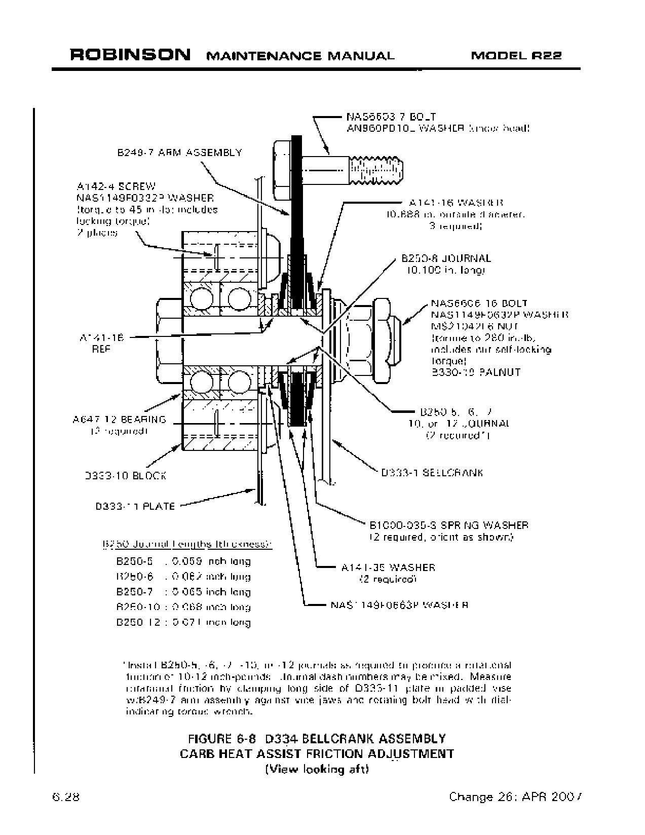
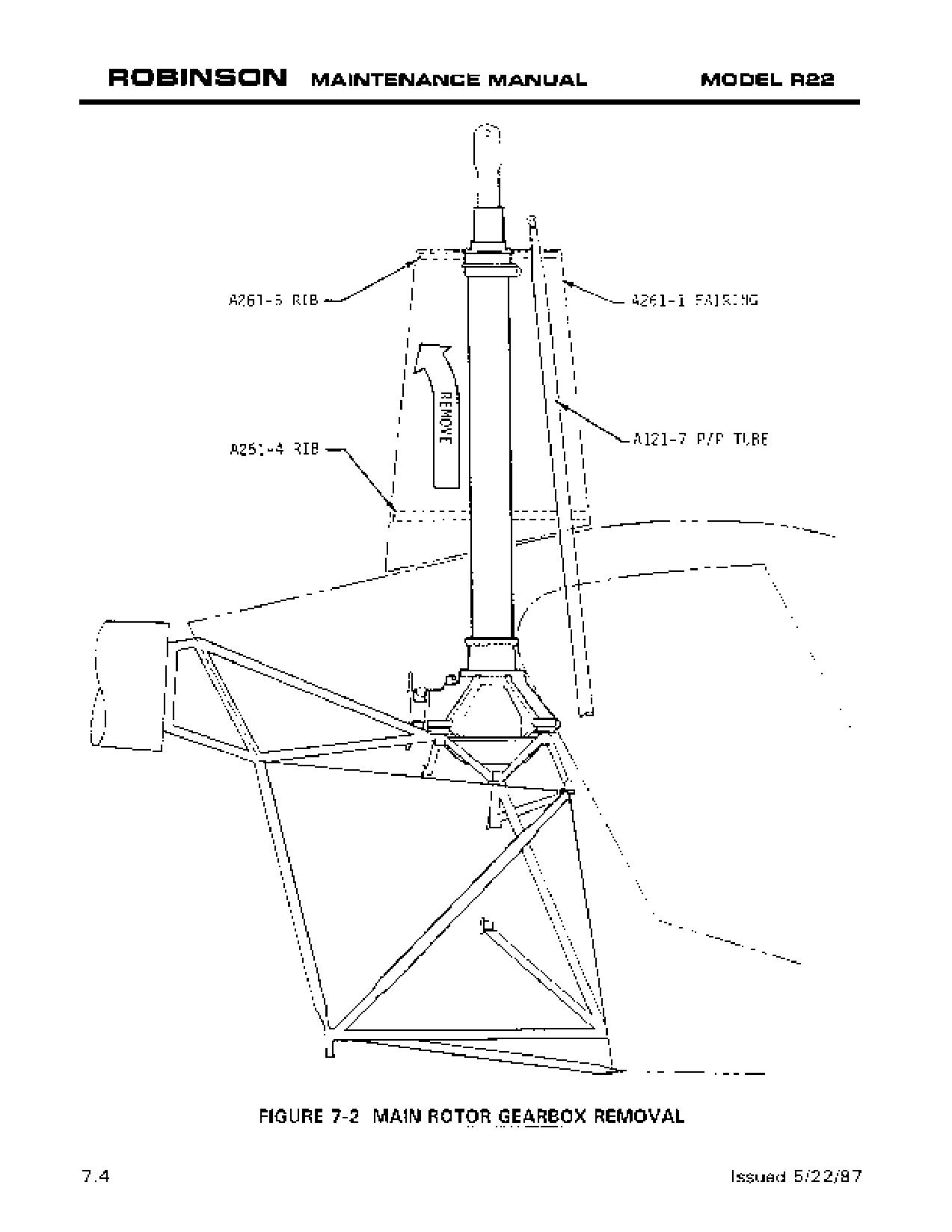
10. Remove four main rotor gearbox mounting bolts. Carefully lift gearbox up to clear
forward push-pull tubes and remove gearbox (see Figure 7-2).
WARNING
Leveling shims may be installed between gearbox mounts and
frame mounting pads. Shims should remain attached to frame,
or mark mounting pads with shim thickness for reinstallation.
OCT 2014
Chapter 7 Drive Train
Page 7.1
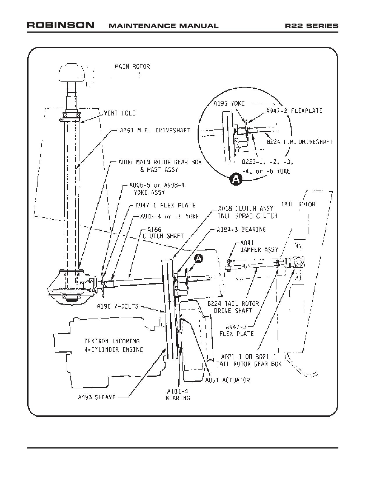
FIGURE 7-1 DRIVE TRAIN
Page 7.2
Chapter 7 Drive Train
OCT 2014
7.140 A006-5 or A908-4 Yoke Removal and Installation
Yoke Removal:
a) Remove A947-1 flex plate and remove clutch per § 7.210 or support clutch shaft per
Figure 7-8.
b) Place a wooden block between horizontal firewall and yoke flange to counteract
torque when loosening nut.
c) Remove cotter pin and nut from main rotor gearbox pinion shaft and remove yoke.
Yoke Installation:
a) Install A006-5 or A908-4 yoke on main rotor gearbox pinion shaft. Install A141-10
washer and AN320-8 castellated nut.
b) Special torque nut per § 23-33 and install cotter pin. Place a wood block between
yoke flange and horizontal firewall to counteract torque.
c) Install clutch assembly, if removed, and connect forward flex plate per § 7.220.
WARNING
A193 flex plates, which do not have bonded washers, are
obsolete and must be replaced with A947 flex plates having
bonded washers. If a bonded washer separates from an A947
flex plate, flex plate is unairworthy and cannot be repaired.
Ensure A947-1 forward flex plate is Rev E or subsequent
(identified by letter “E” or subsequent letter on two arms of
flex plate).
d) Check Hall Effect sender-to-yoke magnet gap per § 7.141 before run-up or turning
blades.
7.141 Setting Hall Effect Sender Gap
Hall Effect sender-to-magnet gap is 0.020 inch ± 0.005 inch. Gap is adjustable by
loosening sender jam nuts. Check gaps between bolt magnets at each sender. After
setting gap, tighten jam nuts and torque-stripe.
7.150 Replacement of Main Rotor Gearbox Pinion Seal
a) Ensure belt tension actuator is fully disengaged. Disconnect A947-2 intermediate flex
plate at tail rotor drive shaft. Note shim location(s) for reinstallation.
b) Remove A947-1 forward flex plate. Note shim location(s) for reinstallation.
OCT 2018
Chapter 7 Drive Train
Page 7.7
Intentionally Blank
Page 7.8
Chapter 7 Drive Train
OCT 2018
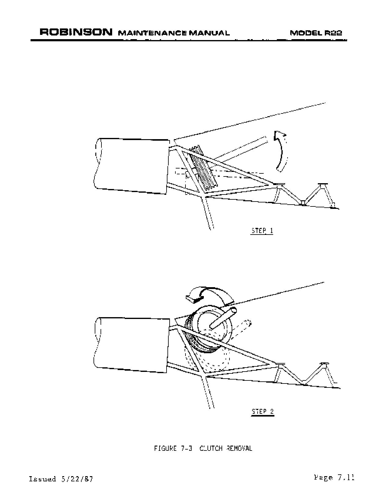
7.213 Clutch Assembly Seal Replacement
1.
Remove clutch assembly per § 7.210.
2.
If replacing aft seal, remove A184-3 bearing assembly from clutch shaft per § 7.211.
Remove loose paint and clean shaft.
NOTE
Orient clutch assembly vertically with leaking seal up.
3.
Remove inner circle of six (6) bolts from leaking seal retainer.
a. If seal retainer is circular with two opposing half-moon-shaped cutouts: Remove
four (4) bolts in outer row, but not two (2) bolts with large-area washers (which
holds inner clutch assembly together).
NOTE
DO NOT REMOVE two bolts holding the inner clutch assembly
together. Further disassembly is not approved.
b. If seal retainer has two socket-head cap screws: Remove six bolts in outer
row, and two socket-head cap screws.
4.
Lift retainer plate with seal off shaft per Figure 7-3C. Remove exposed 0-ring from
clutch housing and discard.
5.
Press damaged seal out of retainer.
6.
Measure retainer seal bore. If bore measures over 1.687 inches, retainer must be
replaced.
7.
For “National” brand seals coat seal bore of retainer with B270-3 sealant and press
seal in at room temperature. For “CR” brand seal with green coating on seal outer
diameter, heat retainer to 150°F and press seal in dry. Press new seal into retainer
flush with outside lip.
8.
Fill sprag and bearing cavity with A257-4 oil until oil level is flush with top of
bearing races (see Figure 7-3D). Rotate shaft while filling to ensure complete filling
of inner shaft and sprag assembly.
9.
Lightly lubricate new 0-ring with A257-4 oil and place it in clutch housing groove.
10.
Lightly lubricate seal inner lip with A257-4 oil and slide retainer over shaft.
OCT 2018
Chapter 7 Drive Train
Page 7.15
7.213 Clutch Assembly Seal Replacement (continued)
11. a. If seal retainer is circular with two opposing half-moon shaped cutouts: Position
retainer so cut outs fit over two (2) A141-14 washers holding clutch assembly
together. Install six (6) inner and remaining four (4) outer bolts in retainers with
heads toward shorter end of clutch shaft.
b. If seal retainer has provisions for two socket-head cap screws: Install cap screws
with washers and tighten only enough to clamp retainer to o-ring. Install six
inner and six outer bolts with heads toward shorter end of clutch shaft.
12. Using a criss-cross pattern, standard torque nuts per § 23-32 and torque stripe.
13. If installed, fully tighten cap screws and torque stripe.
14. If removed, install A184-3 bearing assembly per § 7.212.
15. Install clutch assembly per § 7.220.
7.214 Clutch Assembly Lubricant Inspection and Servicing
This section has been moved to § 22-30.
Page 7.16
Chapter 7 Drive Train
OCT 2018
7.220 Clutch Assembly Installation
1.
If removed, install A195 and/or A907 yokes per §§ 7.260 & 7.270.
2.
If removed, connect clutch lateral centering strut to A184 bearing assembly and
standard torque fasteners per § 23-32.
3.
Ensure actuator is fully disengaged.
4.
Identify type (deep-groove or shallow-groove) of upper and lower sheaves. Refer to
Figures 7-3D & 2-11.
CAUTION
RHC does not recommend using A170-1 or -2 Revision N or prior
upper sheaves with A493-1 Revision T or later lower sheaves.
Such combinations may cause excessive drive belt vibration.
5.
Install clutch assembly and pull belts over clutch aft yoke. Install belts in proper fore/
aft order with proper direction of rotation.
6.
Attach clutch assembly to clutch actuator. Standard torque fasteners per § 23-32.
7.
Install A947-1 flex plate. Standard torque fasteners per § 23-32.
WARNING
A193 flex plates, which do not have bonded washers, are
obsolete and must be replaced with A947 flex plates having
bonded washers. If a bonded washer separates from an A947
flex plate, flex plate is unairworthy and cannot be repaired.
A947-1 flex plate must be marked with letter “E” (or subsequent
letter) on two adjacent arms.
8.
Connect clutch lateral centering strut from clutch assembly to upper frame. Standard
torque fasteners per § 23-32.
9.
Check clutch sheave alignment per § 7.230 and adjust as required.
10.
Install A947-2 intermediate flex plate per § 7.330.
11.
Adjust actuator down-limit stop screw (see Figure 7-15) for V-belt deflection shown
in Figure 7-7A.
12.
Perform run-up per § 2.210. Adjust actuator down-limit stop screw as required and
tighten down-limit stop screw jam nut.
13.
Torque stripe fasteners per Figure 2-1.
OCT 2018
Chapter 7 Drive Train
Page 7.19
7.230 Clutch Sheave Alignment
1.
Check engine shimming installation limits per § 6.130. Ring-gear-to-frame dimension
must be within specified limits before sheave alignment is checked.
2.
Engage clutch (fan and scroll must be installed).
3.
Check clutch shaft angle per § 7.240.
4.
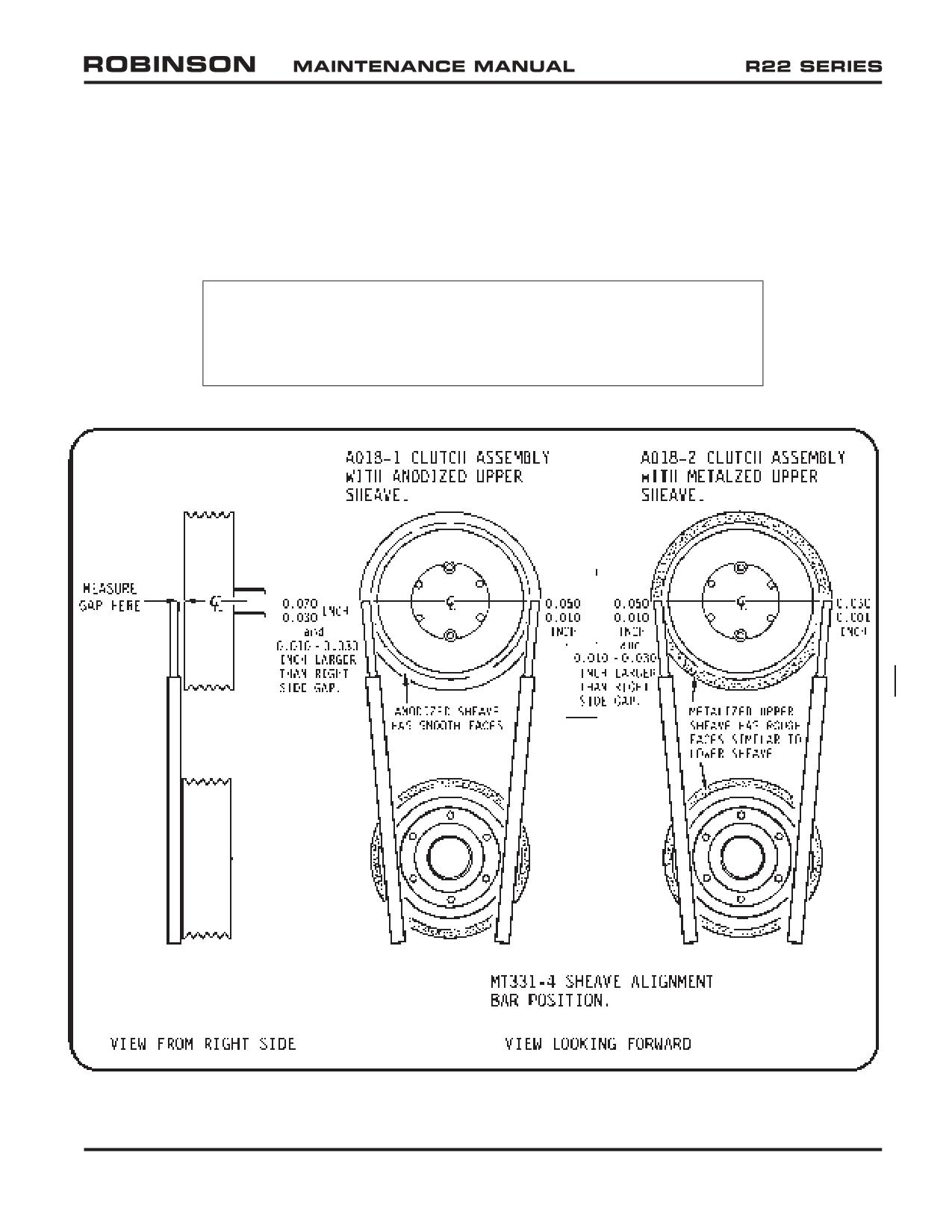
Hold MT331-4 sheave alignment bar against aft face of lower sheave extending bar
upward to horizontal center line of clutch assembly upper sheave.
5.
Measure left and right gaps per Figure 7-5. Both gaps must be within noted limits and
left gap must be 0.010-0.030 inch larger than right gap. If left gap is not 0.010-
0.030 inch larger than right gap, adjust clutch lateral centering per § 7.250 or adjust
engine shims.
If either gap exceeds maximum limit, clutch assembly is too far forward or engine is
too far aft. Engine may be moved forward by removing an equal amount of shims from
each engine mount, subject to § 6.130 minimum shim requirement. Alternatively,
the clutch assembly may be moved aft by shimming at forward flex plate and/or
adjusting A907 yoke length. Shimming is accomplished by installing a maximum of
one AN960-516L washer between A947-1 flex plate and both arms of A907 and/or
A908 yoke; AN960-516L washers installed on either yoke will decrease right and left
gaps an amount equal to the washer’s thickness. A907-4 and -5 yokes each have two
sets of mounting holes which change effective yoke length by 0.120 inch. A907-5
yoke is 0.120 inch or 0.240 inch longer than long position of A907-4 yoke, depending
on mounting holes used. Right and left gaps will decrease by 0.120 inch with each
0.120 inch increase in A907 yoke length.
If either gap is smaller than minimum limit, clutch assembly is too far aft or engine is
too far forward. Engine may be moved aft by adding an equal amount of shims to each
engine mount, subject to § 6.130 maximum shim allowance. Alternatively, clutch
assembly may be moved forward by removing shims (if installed) at forward flex plate
and/or adjusting A907 yoke length. Removing AN960-516L washers from between
A947-1 flex plate and both arms of A907 and/or A908 yoke will increase both gaps
an amount equal to washer’s thickness. A907-4 and -5 yokes each have two sets of
mounting holes which change effective yoke length by 0.120 inch. A907-4 yoke is
0.120 inch or 0.240 inch shorter than short position of A907-5 yoke, depending on
mounting holes used. Right and left gaps will each increase by 0.120 inch with each
0.120 inch decrease in A907 yoke length.
CAUTION
Disengage clutch prior to shimming A947-1 flex plate.
A907-4 yoke replaces A907-1 and -2 yokes. A907-5 yoke replaces A907-3 yoke and
includes an additional set of mounting holes.
Page 7.20
Chapter 7 Drive Train
OCT 2018
7.230 Clutch Sheave Alignment (continued)
6. Check intermediate flex plate shimming per § 7.330 if shims were added or removed
at A947-1 flex plate or if A907 yoke position changed.
7. Adjust V-belt guide per Figure 7-8A.
8. Check throttle correlation rigging per § 10.150 and adjust as required.
NOTE
Shortening clutch lateral centering strut simultaneously increases
left gap and decreases right gap. Lengthening clutch lateral
centering strut decreases left gap and increases right gap.
FIGURE 7-5 SHEAVE ALIGNMENT
OCT 2018
Chapter 7 Drive Train
Page 7.21
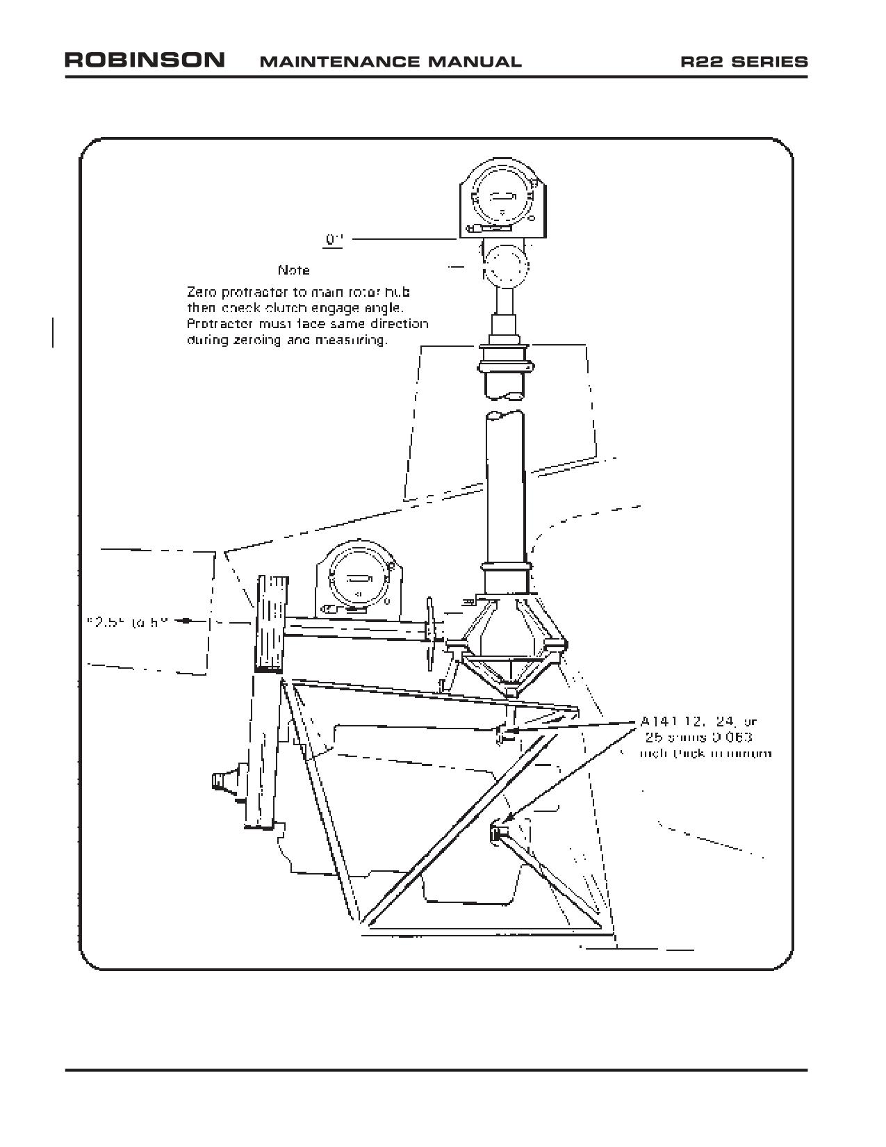
FIGURE 7-6 MEASURING CLUTCH SHAFT ANGLE
Page 7.22
Chapter 7 Drive Train
OCT 2018
7.240 Clutch Shaft Angle
Verify correct engine shimming per § 6.130 prior to checking clutch shaft angle.
1. See Figure 7-6. Orient main rotor blades perpendicular to centerline of helicopter.
Position protractor atop main rotor hub facing right side of helicopter as shown.
Zero protractor to main rotor hub.
2. Turn master switch on and engage clutch. Check angle of clutch shaft per Figure 7-6.
3. Clutch shaft angle limits with clutch engaged are 2.5 to 5.0 degrees.
Flex plate has zero vertical misalignment when angle is 3.5 degrees. If clutch shaft
angle is not within limits, drive V-belts must be replaced.
7.250 Clutch Lateral Centering
1. Clutch actuator fully engaged.
2. Check sheave alignment on left and right side per Figure 7-5.
3. To facilitate sheave alignment, left gap should be 0.010 to 0.030 inch larger than right
gap. Clutch lateral centering strut may be adjusted (with clutch engaged) to obtain
gap differential provided following clearances are met:
a. Minimum 0.030 inch between clutch actuator motor and upper frame tube.
b. Minimum 0.150 inch between V-belts and right side frame guard (actuator engaged).
4. If alignment cannot be adjusted within required measurements, contact Robinson
Helicopter Company Technical Support.
5. Standard torque attach bolts and jam nuts per § 23-32.
OCT 2018
Chapter 7 Drive Train
Page 7.23
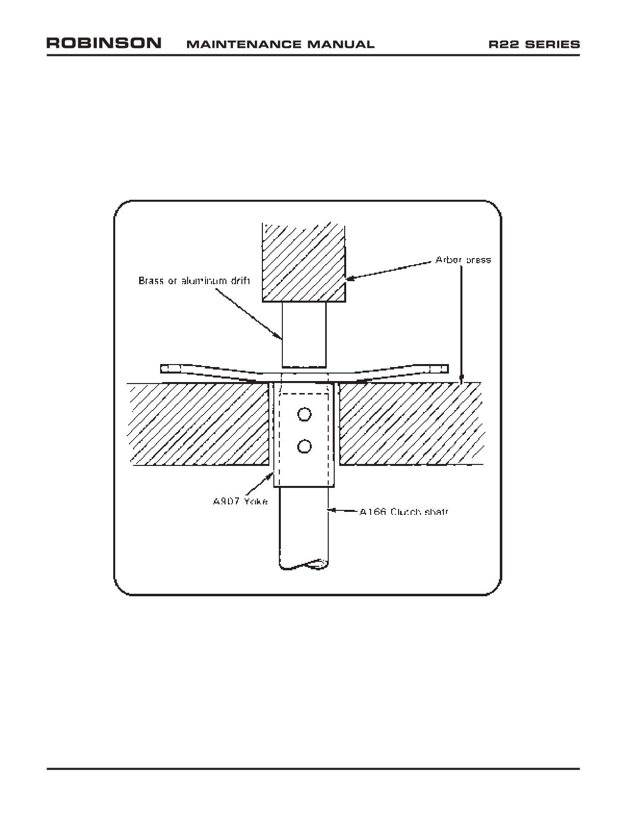
FIGURE 7-6A A907 YOKE REMOVAL
Page 7.24
Chapter 7 Drive Train
OCT 2018
7.260 A907 Yoke Removal and Installation
To remove yoke:
1. Remove clutch assembly per § 7.210.
2. Remove bolts and clamping blocks securing A907 yoke to clutch shaft. Mark which
set of yoke attachment holes are used.
3. Remove A907 yoke:
a. (Preferred method) If a press is available, position clutch assembly in press per
Figure 7-6A. Ensure brass or aluminum drift fits against outer rim of clutch
shaft and not against inner spacer. Press clutch shaft out of yoke.
CAUTION
Ensure clutch assembly does not fall when yoke is removed.
b. If a press is not available, apply penetrating oil to yoke-shaft juncture. Gently
clamp A907 yoke in a padded vise per Figure 7-6B. Twist clutch shaft out of
yoke by turning upper sheave. If difficulty is encountered, discontinue attempt
and arrange use of press as described in preceding step.
CAUTION
Avoid bending loads on clutch shaft when A907 yoke is clamped
in vise as yoke can be damaged.
To install yoke:
1. Remove paint from and clean mating area on clutch shaft.
2. Remove paint from A907 yoke bore, from A907 yoke exterior at clamping block
attachment areas, and from clamping surfaces of clamping blocks.
3. Coat A907 yoke bore and mating portion of clutch shaft with § 23-70 approved
zinc-chromate or epoxy primer. While primer is still wet, install yoke on clutch shaft
and align marked holes on yoke (if applicable) with clutch shaft holes.
CAUTION
Use only specified primers to install yoke; do not use any other
lubricants.
4. While yoke primer is still wet, secure yoke to shaft with clamping blocks coated
with approved zinc-chromate or epoxy primer and bolts. Standard torque bolts per
§ 23-32. Install palnuts and standard torque per § 23-32.
5. Clean all exposed bare metal fasteners and joints, and prime with zinc-chromate or
epoxy primer. Ensure formation of primer fillets at all joints for sealing out moisture.
6. Torque stripe fasteners.
OCT 2018
Chapter 7 Drive Train
Page 7.25
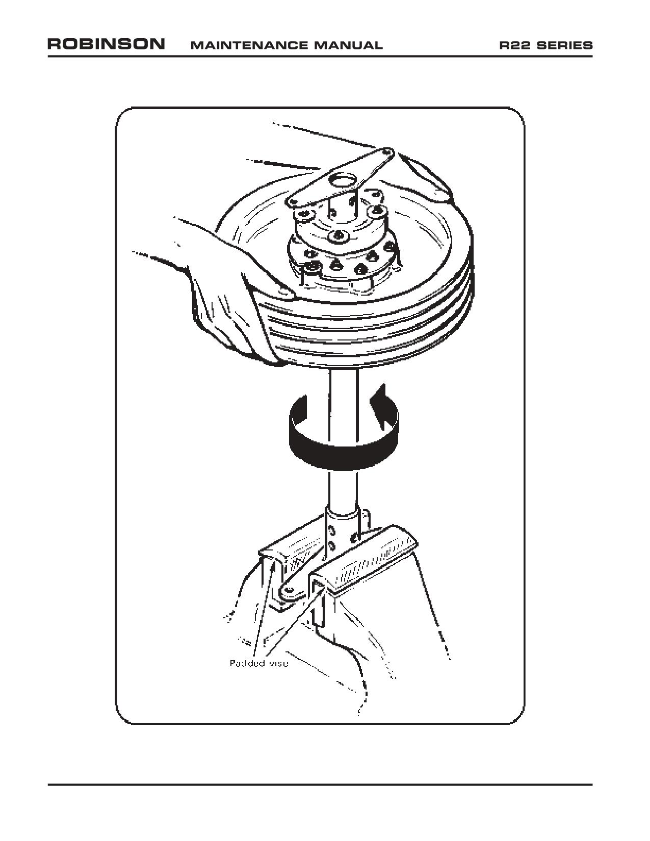
FIGURE 7-6B A907 YOKE REMOVAL
Page 7.26
Chapter 7 Drive Train
OCT 2018
Intentionally Blank
OCT 2018
Chapter 7 Drive Train
Page 7.27
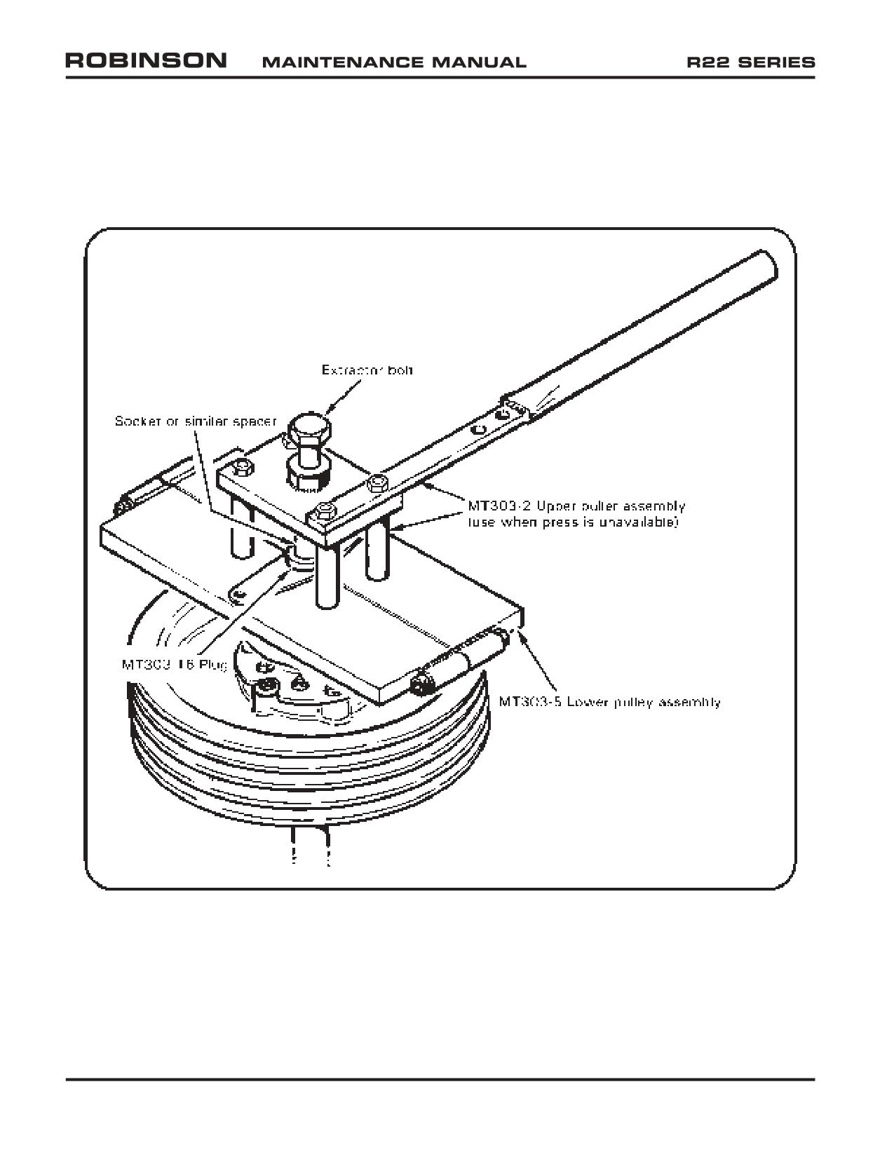
FIGURE 7-6C A195 YOKE REMOVAL
Page 7.28
Chapter 7 Drive Train
OCT 2018
7.270 A195 Yoke Removal and Installation
1. Remove clutch assembly per § 7.210.
2. Remove bolts and clamping blocks securing A195 yoke to clutch shaft.
CAUTION
A195 yoke arms are easily bent. Exercise care when removing
or installing yoke. Always remove A195 yoke when shipping
or transporting clutch assembly.
3. Remove A195 yoke:
a. If a press is available, assemble MT303-5 lower puller assembly around clutch
shaft between A184 bearing and A195 yoke. Flat face of puller must be towards
yoke. Refer to Figure 7-6C. Insert MT303-16 plug thru A195 yoke bore into
clutch shaft and press shaft out of yoke.
b. If a press is not available, assemble MT303-5 lower puller assembly with MT303-2
upper puller assembly per Figure 7-6C. Flat face of puller must be towards yoke.
Insert MT303-16 plug thru A195 yoke bore into clutch shaft. Place a deep
socket (or similar) between MT303-16 plug and extractor bolt. Tighten bolt and
remove A195 yoke.
To install yoke:
1. Remove paint from and clean mating area on shaft.
2. Remove paint from A195 yoke bore, from A195 yoke exterior at clamping block
attachment areas, and clamping surfaces of clamping blocks.
3. Coat inside of A195 yoke and mating portion of clutch shaft with § 23-70 approved
zinc chromate or epoxy primer. While primer is still wet, slide A195 yoke onto clutch
shaft and align mounting holes.
4. While yoke primer is still wet, secure yoke to shaft with clamping blocks coated
with approved zinc-chromate or epoxy primer and bolts. Standard torque bolts per
§ 23-32. Install palnuts and standard torque per § 23-32.
5. Clean all exposed bare metal fasteners and joints, and prime with zinc-chromate or
epoxy primer. Ensure formation of primer fillets at all joints for sealing out moisture.
6. Torque stripe fasteners.
OCT 2018
Chapter 7 Drive Train
Page 7.29
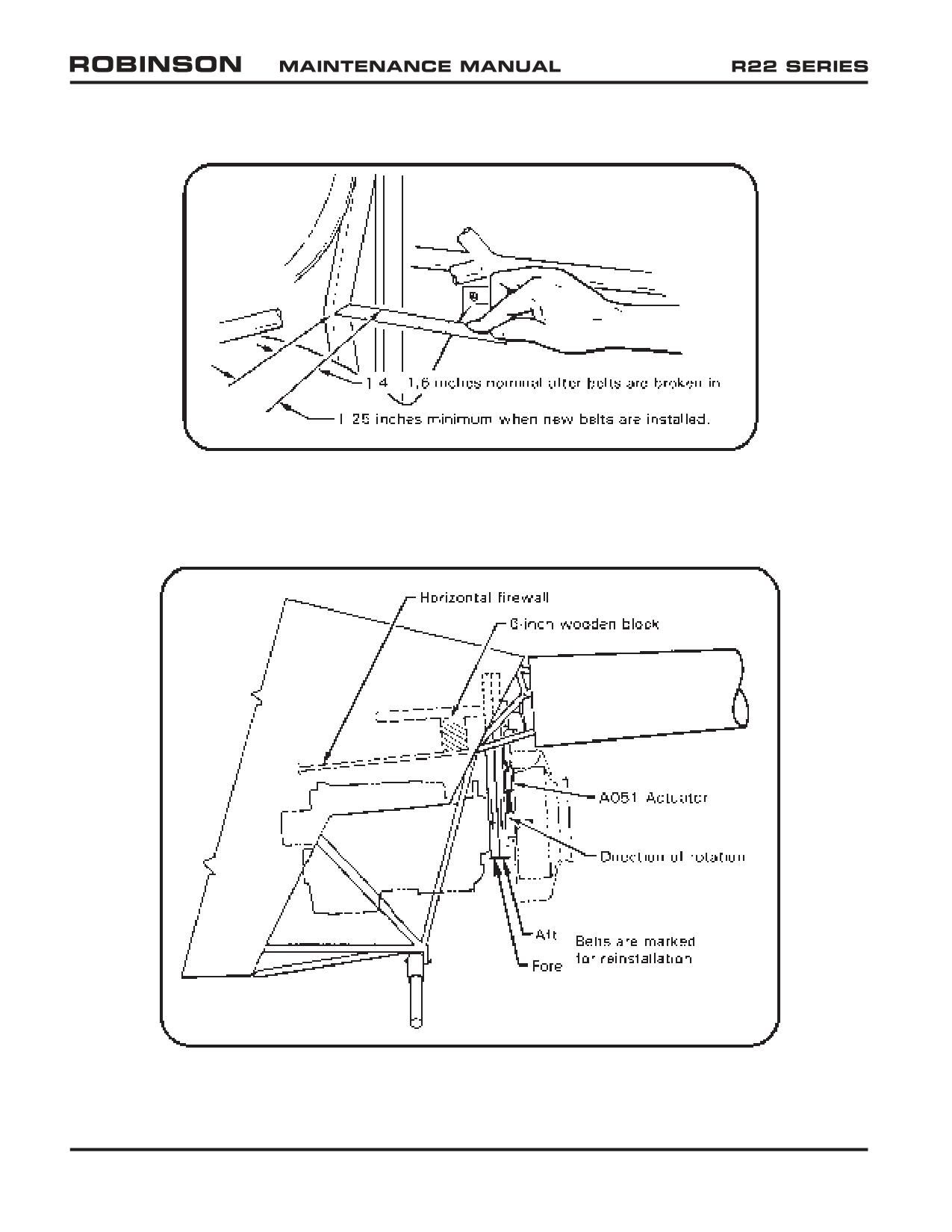
FIGURE 7-7A V-BELT DEFLECTION (ACTUATOR DISENGAGED)
FIGURE 7-8 V-BELT AND ACTUATOR REMOVAL
Page 7.29A
Chapter 7 Drive Train
OCT 2018
7.280 V-Belts
7.281 V-Belt Removal
a. Remove fanwheel per § 6.210.
b. Fully disengage belt tension actuator. Place a six-inch wooden block between clutch
shaft and horizontal firewall per Figure 7-8. Block will prevent excessive sheave
drop and protect forward flex plate.
c. Disconnect clutch lateral centering strut from upper frame and remove intermediate
flex plate.
d. Mark drive belts for “fore” and “aft” position and direction of rotation if they will be
reinstalled.
CAUTION
Used belts must be reinstalled in proper order due to individual
differences in belt stretch.
e. Loosen belt guide and position guide to remove v-belts.
f. Disconnect actuator wiring.
g. Remove belts from sheave and pull over aft yoke.
7.282 V-Belt Installation
1. Evaluate alternator belt(s) condition and replace as required.
2. Inspect upper and lower actuator bearings per §§ 2.502 & 2.503 (lubricate as required).
3. Identify type (deep-groove or shallow-groove) of upper and lower sheaves. Refer to
Figures 7-3D & 2-11.
CAUTION
RHC does not recommend using A170-1 or -2 Revision N or prior
upper sheaves with A493-1 Revision T or later lower sheaves.
Such combinations may cause excessive drive belt vibration.
4. Inspect both sheaves. Replace any sheave showing corrosion, pitting or flaking
of the metalized or anodized coatings, wear through anodized coating, grooves,
roughness, or sharp ridges.
CAUTION
Rough or corroded grooves in the upper or lower sheave can
cause V-belts to roll, break, or come off.
OCT 2018
Chapter 7 Drive Train
Page 7.29B
7.282 V-Belt Installation (continued)
5.
Paint lower sheave grooves with a thin coating of zinc-chromate or epoxy primer
(ref. § 23-70). Sheave may be primed without removal by using an aerosol can or
air brush.
6.
Inspect belts per § 2.507.
7.
Install belts on sheaves. Ensure belts are installed in proper fore/aft order with
proper direction of rotation.
WARNING
V-belts are a matched set. Only install V -belts as matched set.
8.
Connect actuator wiring.
9.
Connect lateral centering strut bolts and standard torque per § 23-32.
10.
Install fanwheel and scroll per § 6.220.
11.
Measure belt defection with actuator disengaged. Using a scale and finger pressure,
belts must deflect inward 1.4-1.6 inches per Figure 7-7A. Adjust actuator down-
limit stop screw (see Figure 7-15) as required to obtain correct dimension. Tighten
down-limit stop screw jam nut.
CAUTION
Belts which are too tight can damage flex plates during start
and belts which are too loose can jump out of grooves during
engagement.
NOTE
A delay of more than
5 seconds between clutch switch
engagement and rotor turning indicates excessive slack. If
rotor rotates when cranking engine, belts may not have enough
slack. Actuator down limit screw adjustments are required
more frequently with new belts.
12.
Check clutch sheave alignment per § 7.230.
13.
Shim and connect intermediate flex coupling per § 7.330.
14.
Rotate drive train by hand with actuator disengaged. Verify minimum 0.125
inch clearance with new belts (0.25 inch after approximately 10 hours) between
intermediate flex coupling and A331-1 tail rotor bellcrank-to-A121-17 push-pull tube
attach bolt. If clearance less than minimum, shim engine per § 6.130.
15.
Position V-belt guide to maintain clearance specified in Figure 7-8A. Standard torque
attach hardware per § 23-32.
Page 7.30
Chapter 7 Drive Train
OCT 2018
7.282 V-Belt Installation (continued)
16. If required, install protective clamp on upper frame per Figure 2-4C.
17. Ground run or hover helicopter for at least one-half hour.
18. At end of half-hour run, inspect primer wear pattern in lower sheave grooves. A
similar wear pattern in all four grooves indicates compatible belt/sheave combination.
A noticeably different wear pattern from groove to groove indicates combination is
not compatible. Refer to § 2.508 for allowable wear pattern limits.
19. If belt/sheave combination is not compatible, re-check sheave alignment, replace
belts, and repeat installation procedure. If belt/sheave combination is still not
compatible, it may be necessary to replace lower sheave. Wear pattern in all four
grooves must be similar before aircraft is released for flight.
20. Check clutch shaft angle per § 7.240.
OCT 2018
Chapter 7 Drive Train
Page 7.31
Intentionally Blank
Page 7.32
Chapter 7 Drive Train
OCT 2018
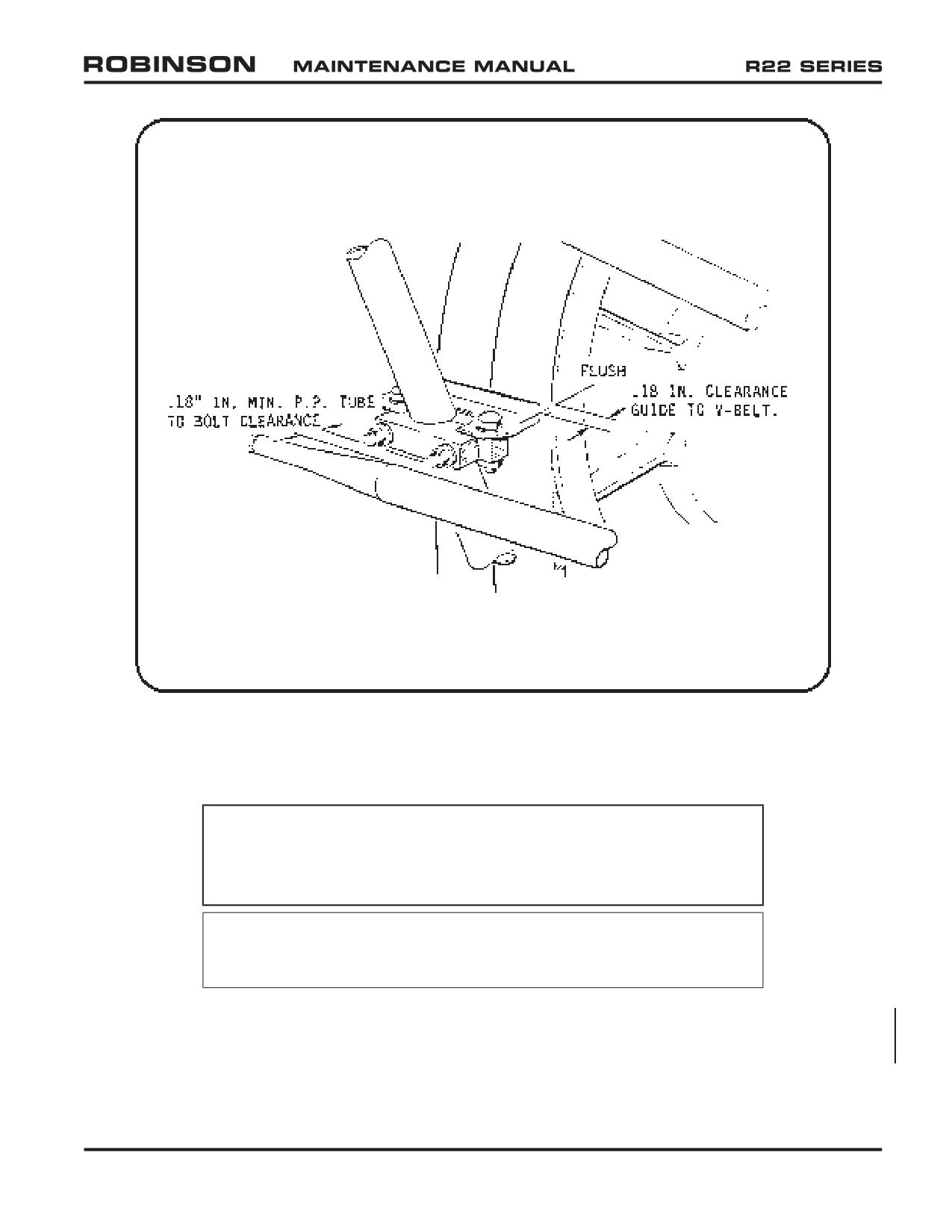
FIGURE 7-8A V-BELT GUIDE
7.282 V-Belt Installation (continued)
CAUTION
Position guide to 0.18 inch clearance with clutch engaged.
Guide to be flushed with front face of sheave. Maintain 0.18
inch clearance between P/P tube and guide attach bolts.
NOTE
A020-2 upper frame S/N 0501 and subsequent have guide
bracket welded to frame.
OCT 2014
Chapter 7 Drive Train
Page 7.33
7.290 A007-3 & -5 Fanshaft and Bearing Assembly, Starter Ring Gear Support,
Lower Sheave and Alternator Belt Replacement
7.291 Removal
a. Remove fanwheel and fiberglass scroll per § 6.210.
NOTE
Fanwheel and fiberglass scroll may be removed without splitting
scroll.
b. Support clutch shaft assembly at horizontal firewall with a wooden block.
Remove lower bolt connecting belt tension actuator to A181-4 lower bearing
assembly.
c. Label drive belts (forward & aft) for reinstallation.
d. Cut safety wire and remove six NAS6606-24H bolts. Note number and thickness
of washers under each bolt head.
e. Remove A007-3 or -5 fanshaft and bearing assembly. Temporarily secure lower
sheave if it is not to be removed.
f. To remove lower sheave, tap it with a soft mallet while pulling.
g. Removal of starter ring gear support is required to change alternator belt or gain
access to engine nose section.
1. Loosen alternator belt tension.
2. Note “0” mark on the starter ring gear support at one crankshaft flange
bushing. Mark this bushing to ease reinstallation.
3. Remove starter ring gear support.
7.292 Installation
a. Install new and spare alternator belts if required. Install starter ring gear support.
Align “0” mark on ring gear support with marked bushing. Bushing and hole
marked 0 are slightly larger than other five holes.
b. Install lower sheave and fanshaft assembly. Ensure one AN960-616 and one
AN916-616L washer is installed under each NAS6606-24H bolt head. Torque
bolts per § 1.320 in a crossing pattern. Safety wire bolts in pairs with 0.041
inch diameter stainless steel safety wire.
CAUTION
One AN960-616 washer and one AN960-616L washer must
be installed under each NAS6606-24H bolt head for proper
fanshaft-sheave-crankshaft clamp-up.
Page 7.33A
Chapter 7 Drive Train
OCT 2014
7.400 Tail Rotor Gearbox
7.410 Tail Rotor Gearbox Removal
1. Mark tail rotor hub and blades and tail rotor pitch links to their respective pitch control
arms before disassembly. This will facilitate reinstallation and eliminate re-rigging tail
rotor if push-pull tube lengths are not altered.
2. Remove tail rotor assembly. Leave pitch control links attached to tail rotor blades.
3. Disconnect A120-1 bellcrank from push-pull tube.
4. Disconnect A120 bellcrank from gearbox and reassemble bellcrank hardware to
bellcrank. Slide pitch control, with bellcrank attached, off gearbox output shaft.
5. Disconnect gearbox chip detector wire at quick disconnect.
6. Remove tail rotor driveshaft per § 7.310.
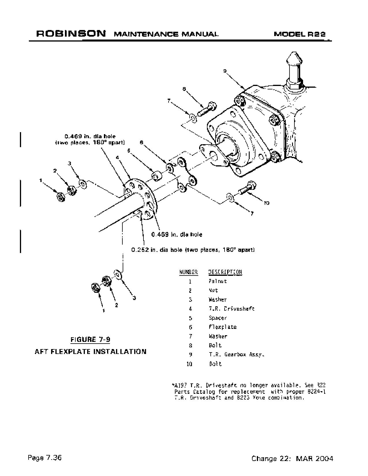
7. Remove aft flex plate from gearbox. Reinstall bolts, spacers, and nuts on flex plate to
prevent loss.
7.420 Tail Rotor Gearbox Installation
1. Install tail rotor drive shaft per § 7.320.
WARNING
A193 flex plates, which do not have bonded washers, are
obsolete and must be replaced with A947 flex plates having
bonded washers. If a bonded washer separates from an A947
flex plate, flex plate is unairworthy and cannot be repaired.
2. Install tail rotor pitch control and bellcrank. Check bellcrank to pitch control shimming
per § 8.562.
3. Connect A121-17 push-pull tube to aft bellcrank.
4. Install tail rotor assembly per § 9.213.
OCT 2018
Chapter 7 Drive Train
Page 7.45
7.430 Tail Rotor Gearbox Shimming
Shimming of gearbox at mounting flange is only required when intermediate flexplate gap
between clutch shaft yoke and tail rotor drive shaft forward yoke is too small to allow
installation of flexplate. Gearbox may be shimmed aft a maximum of 0.080 inch. If shims
are installed (3) MS20074-04-06 and (1) NAS1304-8 bolts must be used for gearbox-to-
casting installation. If more than 0.040 inch shims are used, change NAS1149F0463P
washers under bolt heads to NAS1149F0432P. If tail rotor system is rigged and shims
are subsequently installed, extend A121-17 push-pull tube aft rod end 1/2 turn for each
0.018 inch the gearbox is shimmed aft; retract rod end 1/2 turn for each 0.018 inch of
shims removed.
7.440 Tail Rotor Gearbox Chip Indicator
If “TR CHIP” light illuminates:
1. Drain and flush gearbox per § 22-23 except strain oil (a paint filter works well) while
draining and examine any particles found in oil or on chip detector.
2. Particles larger than 0.09 inch long or 0.02 inch wide are cause for concern and
should be identified as ferrous or non-ferrous with a magnet. If particles are ferrous
return gearbox to RHC for repair along with particles. If particles are non-ferrous,
drain and flush gearbox per § 22-23.
3. If “TR CHIP” illuminates again within next 100 hours time-in-service a gearbox failure
may be imminent. Return gearbox to RHC for repair.
Page 7.46
Chapter 7 Drive Train
OCT 2018
7.500 Actuator Assembly
7.510 Actuator Removal
1. Remove tailcone fairing.
2. Full disengage clutch.
3. Remove fanwheel per § 6.210.
4. Put a four-inch wood block under clutch shaft just forward of upper sheave on horizontal
firewall. This keeps sheave from drooping and prevents damage to forward flex plate
per Figure 7-8.
5. Disconnect two wiring connections to actuator.
6. Remove upper and lower NAS6604 bolts connecting actuator to bearings and remove
actuator.
7.520 Actuator Installation
1. Connect actuator to A184 bearing and standard torque bolt per § 23-32. Install
palnut, standard torque per § 23-32, and torque stripe per Figure 2-1.
2. Install lower attach bolt with head facing aft. Use one NAS1149F0432P washer
under bolt head and one NAS1149F0463P washer under nut. Standard torque bolt
per § 23-32. Install palnut, standard torque per § 23-32, and torque stripe per Figure
2-1. Remove wooden block.
3. Install fanwheel per § 6.220.
4. Connect motor and switch assembly electrical leads.
CAUTION
Do not engage actuator without scroll installed.
7.530 Actuator Gearmotor Replacement
Actuator Gearmotor can be replaced with actuator on helicopter.
1. Disconnect gearmotor electrical leads.
2. Cut safety wire from and remove four gearmotor attaching screws. Exercise care
not to drop either safety wire or screws in V-belt sheaves.
3. Slowly slide gearmotor assembly from housing. An unscrewing motion may be
necessary.
4. Lightly lubricate worm gear on new gearmotor assembly with A257-1 grease before
installing. Install o-ring onto gearmotor nose piece.
OCT 2018
Chapter 7 Drive Train
Page 7.49
7.530 Actuator Gearmotor Replacement (continued)
5. Install new gearmotor into housing with wire leads pointing down. Verify no gap
exists between housing and gearmotor mounting flange before installing screws; do
not use screws to draw gearmotor into housing as motor flange can break.
6. Secure gearmotor to housing with four mounting screws and safety wire with 0.020-
inch diameter wire using single strand method.
7. Connect gearmotor electrical leads. Engage clutch, listen for binding, and verify
actuator fully tensions drive belts.
8. Seal all fasteners, seams and openings around gearmotor with B270-8 sealant.
9. Ty-rap gearmotor electrical leads as required.
CAUTION
Severe damage to actuator and drive belts can occur if gearmotor
electrical leads are installed incorrectly in wiring connector
(gearmotor will operate backwards and down-limit switch and
spring switches will not shut off gearmotor current).
7.540 Actuator Adjustment
1. Engaged Limit
The actuator engaged limit is determined by column springs which control drive belt
tension. Column springs may only be adjusted by the factory.
2. Disengaged Down-Limit Adjustment (see Figure 7-15)
The down-limit switch is activated by the down-limit stop screw which can be
adjusted using long 3/8-inch open-end and ¼-inch box-end wrenches. Adjust down-
limit stop screw to maintain proper belt deflection per § 7.282 with actuator fully
disengaged. Minimum clearance between screw heads at scissors is 0.005 inch.
3. Maximum Extension (see Figure 7-15)
Maximum engaged extension is 1.85 inches measured between top of column spring
block and bottom of screw housing. Drive V-belts must be replaced when maximum
extension is encountered.
Page 7.50
Chapter 7 Drive Train
OCT 2018
Intentionally Blank
OCT 2018
Chapter 7 Drive Train
Page 7.51
FIGURE 7-15 ACTUATOR MAXIMUM
ENGAGED (EXTENSION) LIMIT
AND
MINIMUM DISENGAGED
(RETRACTION LIMIT
Page 7.52
Chapter 7 Drive Train
OCT 2018
7.550 Switch and Fuse Replacement
7.551 Switch Replacement
1. Remove actuator from helicopter per § 7.510.
NOTE
Switches may be replaced as a complete harness assembly or
replaced individually by soldering wire connection and installing
heat shrink.
2. Remove each switch by removing attaching screw, nut, washer, and spacing washers
between switch and plate.
NOTE
Bond the four spacing washers to the new switch(es), if
necessary, to ease reassembly.
3. Replace complete switch and wire harness assembly or, if installing a single switch,
cut faulty switch from harness wiring. Cut wires as close to switches as possible.
4. Slide heat shrink over each cut wire. Solder wires to switch and install heat shrink
over solder connection.
5. Reassemble switch(es) to plate. Two spacing washers are installed between switch
and plate at each attach screw and one under nut. Do not over tighten screws or
plastic switch housing may crack.
6. Reinstall actuator on helicopter per § 7.520.
7.552 Fuse Replacement
An in-line fuse holder is installed in clutch actuator motor power circuit. Fuse holder is
mounted on test switch panel. Replace fuse with 1.5 amp (AGC 1.5) fuse.
OCT 2018
Chapter 7 Drive Train
Page 7.53
7.600 Rotor Brake
7.610 Rotor Brake Removal
1. Remove tailcone cowling. Remove forward flex plate. Mark and record any shim
washers installed between flex plate and main rotor gearbox input yoke and/or clutch
shaft yoke.
WARNING
A193 flex plates, which do not have bonded washers, are
obsolete and must be replaced with A947 flex plates having
bonded washers. If a bonded washer separates from an A947
flex plate, flex plate is unairworthy and cannot be repaired.
Ensure A947-1 forward flex plate is Rev E or subsequent
(identified by letter “E” or subsequent letter on two adjacent
arms of flex plate both sides).
2. Remove cotter pin and nut securing input yoke on main rotor gearbox. Remove yoke.
Disconnect brake spring from firewall angle.
3. Disconnect cable from lever. Disconnect wiring to micro switch at three-pin connector.
4. Cut and remove safety wire, then remove three bolts securing rotor brake. Remove
rotor brake assembly.
7.620 Rotor Brake Installation
1. Place rotor brake assembly over splined input pinion shaft of main rotor gearbox.
2. Place one each of two small (A130-41) spacers in place between rotor brake assembly
and pinion end cover. Install one each NAS1149F0432P washer on three NAS1352-
4H30P bolts. Insert first bolt through rotor brake assembly and A130-41 spacer. Insert
second bolt through Hall Effect sender plate, rotor brake assembly and A130-41 spacer.
3. Insert third bolt through Hall Effect sender plate and long A130-41 spacer. Finger
tighten three bolts into gearbox, then special torque bolts per § 23-33 and safety with
0.032 inch diameter safety wire. Attach spring to the firewall angle.
4. Coat splines of pinion shaft with B270-21 protectant before installing yoke. Place
A908-4 yoke on pinion shaft. Install one each A141-10 washer and AN320-8 nut on
pinion shaft. Special torque nut per § 23-33 as required to align castellations on nut
with hole through pinion shaft. Do not exceed 410 in.-lbs. Install one MS24665-210
cotter pin.
5. Set Hall Effect sender-to-magnets gap per § 7.141.
6. Attach cable to lever. Reconnect wiring to micro switch at three-pin connector.
Page 7.54
Chapter 7 Drive Train
OCT 2018
7.620 Rotor Brake Installation (continued)
7. With brake engaged, adjust gap between NAS428-3-12 bolthead on B109-1 arm and
A130-43 spacer to 0.030-0.035 inch. Lock adjustment by tightening MS21042L3 nut.
8. With brake in the released position, measure gap between B112-1 lever and B110-1
arm assembly. The gap measurement should be 0.030-0.170 inch. Adjust length of
bead chain as required to obtain proper gap. One bead is approximately 0.150 inch.
9. Adjust micro switch to open and close at a gap of 0.20-0.30 inch between B112-1
lever and B110-1 arm.
10. lnstall forward flex plate.
11. Check clutch sheave alignment per § 7.230.
12. Install intermediate flex plate per § 7.330.
7.630 Rotor Brake Pad Replacement
1. Minimum pad thickness is 0.030 inch.
2. Brake pad replacement is accomplished by replacing B110-1 and B109-1 arm
assemblies.
OCT 2018
Chapter 7 Drive Train
Page 7.55
Intentionally Blank
Page 7.56
Chapter 7 Drive Train
OCT 2018
CHAPTER 8
FLIGHT CONTROLS
Section Title
Page
8.000
Flight Controls
8.1
8.001
Introduction
8.1
8.002
Description
8.1
8.100
Cyclic Controls
8.1
8.110
Cyclic Assembly
8.1
8.111
Removal of Cyclic Assembly
8.1
8.112
Installation of Cyclic Assembly
8.4
8.120
Cyclic Grip Assembly
8.7
8.121
Removal of Cyclic Grip Assembly
8.7
8.122
Installation of Cyclic Grip Assembly
8.8
8.130
Cyclic Lateral (Right) Trim
8.10
8.131
Right Trim Spring Assembly Removal
8.10
8.132
Right Trim Spring Assembly Installation
8.10
8.133
Right Trim Spring Replacement and Shimming
8.11
8.140
Cyclic Longitudinal (Fore-Aft) Elastic Trim Cord
8.15
8.141
Longitudinal Trim Cord Removal
8.19
8.142
Longitudinal Trim Cord Installation
8.19
8.150
Cyclic Friction Assembly
8.20
8.151
Cyclic Friction Adjustment
8.20
8.160
A121-7 Push-Pull Tube
8.21
8.161
A121-7 Push-Pull Tube Removal
8.21
8.162
A121-7 Push-Pull Tube Inspection/Repair
8.21
8.163
A121-7 Push-Pull Tube Sleeve Installation
8.22
8.164
A121-7 Push-Pull Tube Sleeve Inspection
8.22
8.165
A121-7 Push-Pull Tube Installation
8.23
8.200
Collective Control
8.25
8.210
Collective Stick Assembly
8.25
8.211
Collective Stick Removal
8.25
8.212
Collective Stick Installation
8.26
8.220
Collective Spring Assembly
8.30
8.221
Collective Spring Removal
8.30
8.222
Collective Spring Installation
8.32
8.223
Collective Spring Adjustment for A038-1 thru -4 Assembly
8.33
8.224
Collective Spring Adjustment for A038-5 and -6 Assembly
8.34
OCT 2014
Chapter 8 Flight Controls
Page 8.i
CHAPTER 8
FLIGHT CONTROLS (Continued)
Section Title
Page
8.225
Collective Friction Adjustment
8.34
8.230
RPM Governor System
8.34A
8.231
Governor Controller Removal
8.34A
8.232
Governor Controller Installation
8.34A
8.233
Governor Assembly Removal
8.34A
8.234
Governor Assembly Installation
8.34C
8.239
Governor Troubleshooting
8.34C
8.300
Jackshaft and Support Struts
8.35
8.310
Jackshaft
8.35
8.311
Jackshaft Removal
8.35
8.312
Jackshaft Installation
8.35
8.320
Strut Assembly (Jackshaft Support)
8.35
8.321
Strut Removal
8.35
8.322
Strut Installation
8.38
8.400
Swashplate and Main Rotor Pitch Links
8.39
8.410
Swashplate
8.39
8.411
Swashplate Removal
8.39
8.412
Swashplate Installation
8.40
8.413
(Reserved)
8.414
(Reserved)
8.415
(Reserved)
8.416
Shimming Upper (Unflanged) Spherical Sleeve with Aluminum Ball
8.48
8.500
Tail Rotor Controls
8.48
8.510
Tail Rotor Pedals
8.48
8.511
Tail Rotor Pedal Removal
8.48
8.512
Tail Rotor Pedal Installation
8.52
8.520
A317-1 Lower Bellcrank
8.52
8.521
A317-1 Lower Forward Bellcrank Removal
8.52
8.522
A317-1 Lower Forward Bellcrank Installation
8.53
8.530
A316-1 Upper Bellcrank
8.55
8.531
Bellcrank Removal
8.55
8.532
Bellcrank Installation
8.55
8.540
A331-4 Intermediate Bellcrank
8.56
8.541
Bellcrank Removal
8.56
Page 8.ii
Chapter 8 Flight Controls
OCT 2014