Helicopter Flying Handbook (2019) - page 2
2-22
D
o
wnwa
r
d velo
city o
f
ai
r mo
lec
u
l
es
use
d by
af
t
sect
io
n o
f
roto
r
1–5 knots
10–15 knots
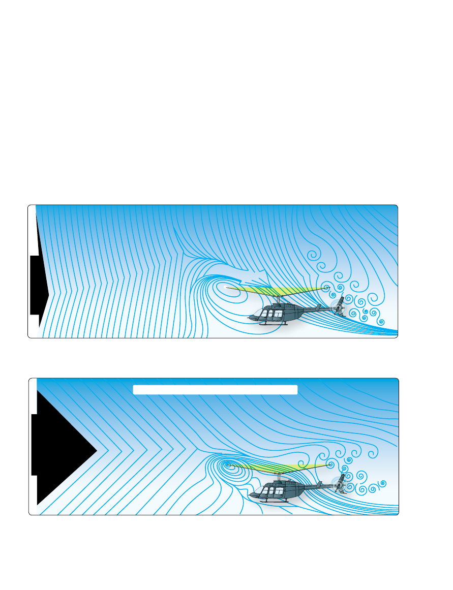
Airflow pattern just prior to effective translational lift
Figure 2-39.
The airflow pattern for 1–5 knots of forward airspeed. Note how the downwind vortex is beginning to dissipate and induced
flow down through the rear of the rotor disk is more horizontal.
Figure 2-40.
An airflow pattern at a speed of 10–15 knots. At this increased airspeed, the airflow continues to become more horizontal.
The leading edge of the downwash pattern is being overrun and is well back under the nose of the helicopter.
As speed increases, translational lift becomes more effective,
nose rises or pitches up, and aircraft rolls to the right.
The combined effects of dissymmetry of lift, gyroscopic
precession, and transverse flow effect cause this tendency.
It is important to understand these effects and anticipate
correcting for them. Once the helicopter is transitioning
through ETL, the pilot needs to apply forward and left
lateral cyclic input to maintain a constant rotor-disk attitude.
[Figure 2-41]
Translational Thrust
Translational thrust occurs when the tail rotor becomes more
aerodynamically efficient during the transition from hover
to forward flight. As the tail rotor works in progressively
less turbulent air, this improved efficiency produces more
antitorque thrust, causing the nose of the aircraft to yaw left
Effective Translational Lift (ETL)
While transitioning to forward flight at about 16 to 24 knots,
the helicopter goes through effective translational lift (ETL).
As mentioned earlier in the discussion on translational lift,
the rotor blades become more efficient as forward airspeed
increases. Between 16 and 24 knots, the rotor disk completely
outruns the recirculation of old vortices and begins to work
in relatively undisturbed air. The flow of air through the rotor
disk is more horizontal, which reduces induced flow and
drag with a corresponding increase in angle of attach and lift.
The additional lift available at this speed is referred to as the
ETL, which makes the rotor disk operate more efficiently.
This increased efficiency continues with increased airspeed
until the best climb airspeed is reached, and total drag is at
its lowest point.
2-23
Helicopter movement
Thrust
Drag
Weight
Lift
Resultant
Resultant
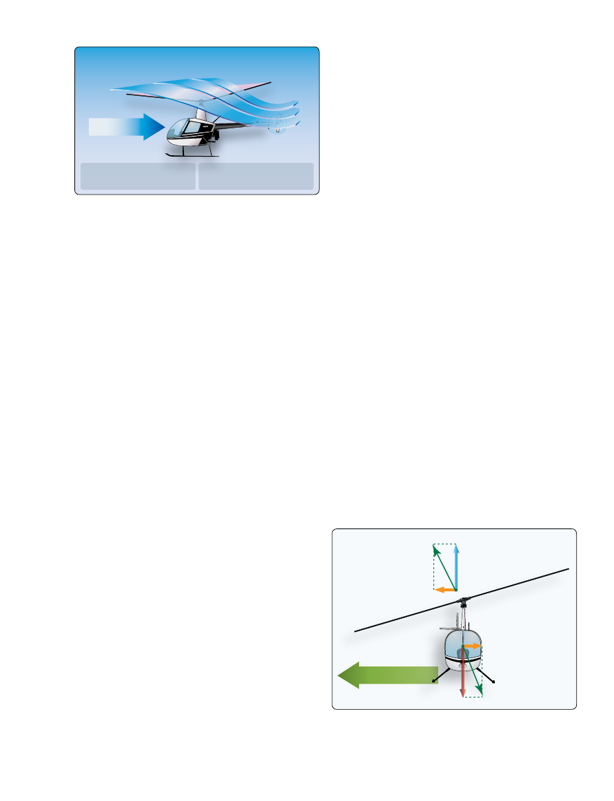
Figure 2-42.
Forces acting on the helicopter during sideward flight.
Figure 2-41.
Effective translational lift is easily recognized in actual
flight by a transient induced aerodynamic vibration and increased
performance of the helicopter.
16–24 knots
No recirculation
of air
More horizontal
flow of air
Reduced induced flow
increases angle of attack
Tail rotor operates in
relatively clean air
Transverse flow effect is recognized by increased vibrations
of the helicopter at airspeeds around 12 to 15 knots and can
be produced by forward flight or from the wind while in a
hover. This vibration happens at an airspeed just below ETL
on takeoff and after passing through ETL during landing. The
vibration happens close to the same airspeed as ETL because
that is when the greatest lift differential exists between the
front and rear portions of the rotor system. As such, some
pilots confuse the vibration felt by transverse flow effect with
passing through ETL. To counteract transverse flow effect,
a cyclic input to the left may be needed.
Sideward Flight
In sideward flight, the tip-path plane is tilted in the direction
that flight is desired. This tilts the total lift-thrust vector
sideward. In this case, the vertical or lift component is still
straight up and weight straight down, but the horizontal or
thrust component now acts sideward with drag acting to the
opposite side.
[Figure 2-42]
Sideward flight can be a very unstable condition due to the
parasitic drag of the fuselage combined with the lack of
horizontal stabilizer for that direction of flight. Increased
altitudes help with control and the pilot must always scan in
the direction of flight. Movement of the cyclic in the intended
direction of flight causes the helicopter to move, controls the
rate of speed, and ground track, but the collective and pedals
are key to successful sideward flight. Just as in forward flight,
the collective keeps the helicopter from contacting the ground
and the pedals help maintain the correct heading; even in
sideward flight, the tail of the helicopter should remain behind
you. Inputs to the cyclic should be smooth and controlled,
and the pilot should always be aware of the tip-path plane in
relation to the ground.
[Figure 2-43]
(with a main rotor turning counterclockwise) and forces the
pilot to apply right pedal (decreasing the AOA in the tail
rotor blades) in response. In addition, during this period, the
airflow affects the horizontal components of the stabilizer
found on most helicopters which tends to bring the nose of
the helicopter to a more level attitude.
Induced Flow
As the rotor blades rotate, they generate what is called
rotational relative wind. This airflow is characterized as
flowing parallel and opposite the rotor’s plane of rotation
and striking perpendicular to the rotor blade’s leading edge.
This rotational relative wind is used to generate lift. As
rotor blades produce lift, air is accelerated over the foil and
projected downward. Anytime a helicopter is producing lift,
it moves large masses of air vertically and down through the
rotor disk. This downwash or induced flow can significantly
change the efficiency of the rotor disk. Rotational relative
wind combines with induced flow to form the resultant
relative wind. As induced flow increases, resultant relative
wind becomes less horizontal. Since AOA is determined
by measuring the difference between the chord line and the
resultant relative wind, as the resultant relative wind becomes
less horizontal, AOA decreases.
[See Figure 2-21]
Transverse Flow Effect
As the helicopter accelerates in forward flight, induced flow
drops to near zero at the forward disk area and increases at the
aft disk area. These differences in lift between the fore and
aft portions of the rotor disk are called transverse flow effect.
[
Figure 2-41]
This increases the AOA at the front disk area
causing the rotor blade to flap up and reduces AOA at the aft
disk area causing the rotor blade to flap down. Because the
rotor acts like a gyro, maximum displacement occurs 90° in the
direction of rotation. The result is a tendency for the helicopter to
roll slightly to the right as it accelerates through approximately
20 knots or if the headwind is approximately 20 knots.