Mi-8MTV2 Magnificent Eight. PC flight simulator manual (2016) - page 3
forward acceleration rate (pitch angle for dive) and increase of engine
power;
helicopter weight;
free air temperature and pressure.
2. If the helicopter does not exit VRS quickly, vertical speed may reach 20 m/s.
3. The pitch angle used in the acceleration out of VRS depends on the altitude of
VRS exit.
ARMAMENT
11
SYSTEMS
DIGITAL COMBAT SIMULATOR Mi-8МТV2
11.
ARMAMENT SYSTEMS
The armament systems of the Mi-8MTV2 helicopter include unguided rockets, cannon
and machine guns, free-falling bombs, and airborne minelaying systems (not
implemented in simulation) in various payload configurations.
The weapons control system is designed to provide weapon firing/release stations,
control of weapon fire modes, and weapons employment. The weapons control
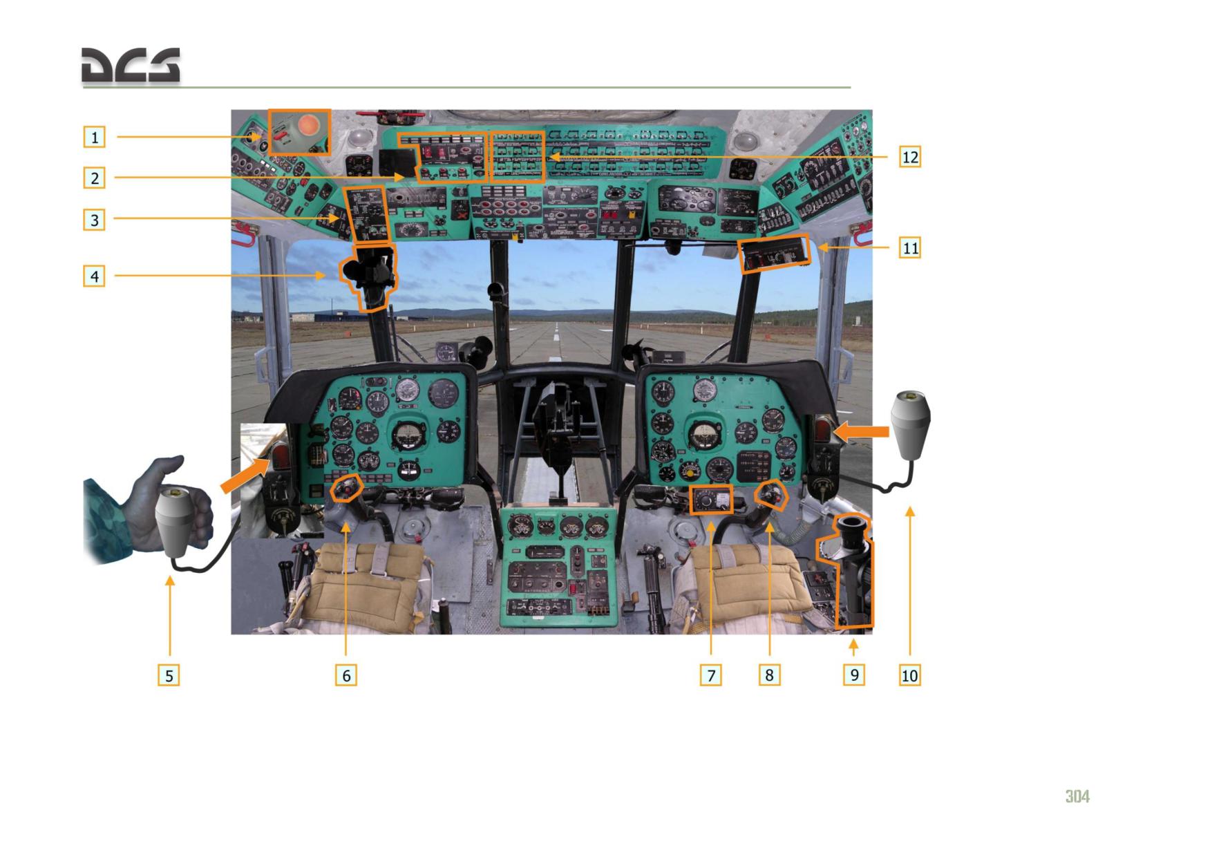
system includes the following components (Fig. 11.1 и Fig. 11.2):
External weapon stations (6 BDZ-57KrV (БД3-57КрВ equipped with "ПУС"
(PUS) fire control devices (FCU))
Circuit breakers and switches operating weapons indication and control
systems
Pilot’s upper and lower armament control panels
Copilot’s bombs control panel
ESBR-3P/A (ЭСБР-3П/А) electrical release control box
Mine release control panel (not implemented in simulation)
Fire control panel for the PKT (ПКТ) nose-mounted machine gun (not
implemented in simulation)
PKV (ПКВ) collimating sight (pilot)
OPB-1r (ОПБ-1р) optical bombing sight (copilot) (not implemented in
simulation)
Weapons fire switches on each cyclic control handle, bomb release
triggers on the OPB-1r (ОПБ-1р) optical bombing sight and two KSB-49
(КСБ-49) remote bomb release triggers
S-13 gun camera
The following weapon sub-systems:
a) unguided rocket system: B8V20-A (Б8В20-А) rocket launchers (pods)
firing 80 mm unguided rockets with various warhead types;
b) cannon pod system: UPK-23-250 (УПК-23-250) gun pods equipped with
GSh-23L (ГШ-23Л) twin-barrel 23 mm cannon;
c) machine gun pod systems: GUV-8700 (ГУВ-8700) gun pod (index 9-A-
669) equipped with either YakB-12.7 (ЯкБ-12.7) (index 9-A-624) and
GShG-7.62 (ГШГ-7.62) (index 9-A-622) machine guns or with the AGS-17
(АГС-17) (index 9-A-800) grenade launcher;
d) free-falling bomb systems: 100, 250 и 500 kg bombs and incendiary
containers (not currently implemented);
e) minelaying system: K-29 mine containers with 29 mine canisters of various
types (currently not implemented).
DIGITAL COMBAT SIMULATOR Mi-8МТV2
1.Master arm switch (above left
blister)
2. Upper armament control panel
3. Lower armament control panel
4. PKV gunsight
5. Left KSB-49 remote bomb
release trigger
6. Left cyclic weapons fire switch
7. Electrical release control box
8. Right cyclic weapons fire switch
9. OPB-1r optical bomb sight (not
currently implemented)
10. Right KSB-49 remote bomb
release trigger
11. Bombs control panel
12. Circuit breaker panel of the
weapons control system
Fig. 11.1. Elements of the weapons control system in the cockkpit.
DIGITAL COMBAT SIMULATOR Mi-8МТV2
11.1. External weapon stations
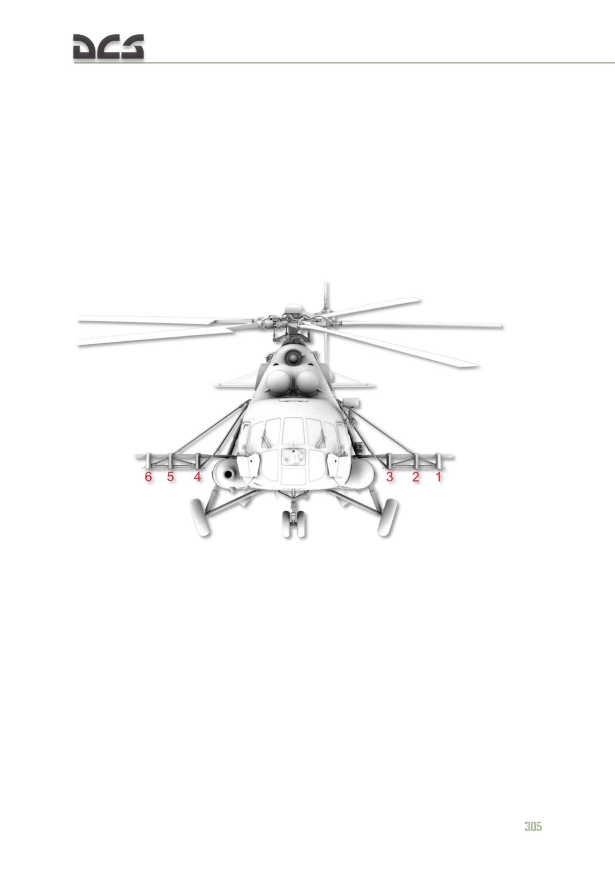
The Mi-8MTV2 is equipped with an external hardpoint rack consisting of 6 БДЗ-
57КрВ (BDZ-57KrV) weapon stations and integrated ПУС (PUS) fire control devices
(FCU). The stations are designed to carry and provide electrical commands to loaded
weapon systems. The hardpoints are numbered 1 - 6 left to right (facing forward in
the cockpit). Stations 1, 3, 4, 6 are equipped with PUS-36-71 (ПУС-36-71) type
FCUs, which are used to control the firing of S-8 unguided rockets at an interval of
0.05 sec for each rocket launcher. ПУС 1 FCU controls rocket fire from stations 1 and
2 (Fig. 11.2); ПУС 6 FCU from stations 5 and 6, ПУС 3 FCU from station 3, and ПУС
4 FCU from station 4. Readiness of the corresponding FCU to support rocket fire is
indicated in the cockpit by the ПУС FCU lights on the pilot’s upper weapons control
panel.
Fig. 11.2. External weapon stations
11.2. Circuit breakers and switches operating Weapons
Indication and Control systems
The weapons system circuit-breakers, located at the top left of the Circuit-Breaker
Panel, are designed to protect the weapon system circuits from a short-circuit. (Fig.
11.3)
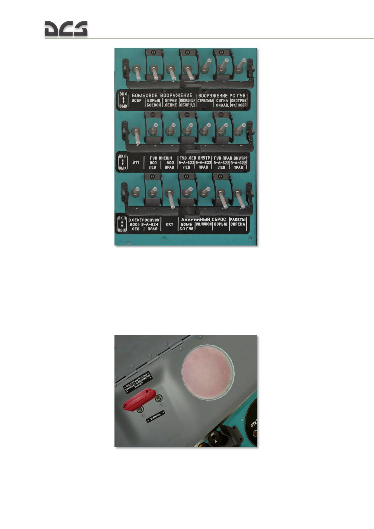
Fig. 11.3. Weapons Systems circuit-breakers.
MASTER ARM. The master arm switch (in EN-cockpit of the Game - SAFETY
SWITCH WEAPONS) connects weapon systems circuits to the weapons fire (release)
switches on the pilot controls (not to be confused with the main power switches of
weapon sub-systems, which connect specific weapon system components to the
electrical power system). With the Master Arm switch off, it will not be possible to
fire (release) weapons. This is a safety precaution required for safe ground
operations with the ground crew and weapons preparation.
Fig. 11.4. The Master Arm switch and its associated red caution lamp.
306
11.3. Pilot's Upper and Lower armament Control Panels
11.3.1. Upper armament Control Panel
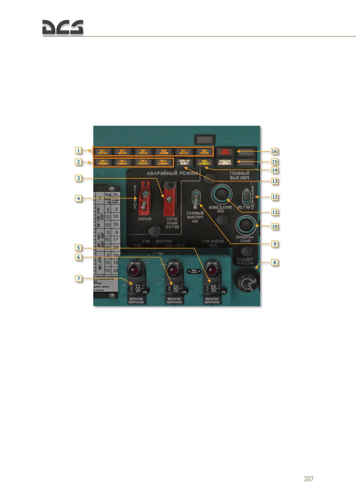
The pilot's upper armament control panel (Fig. 1.5) provides indication of weapon
readiness status, control of the RKT-GUN MASTER switch and MINELAYING SYSTEM
MASTER switches (not currently implemented), payload jettison, arming of the fire
control units (FCU), PKV (ПКВ) collimating sight brightness, and amount remaining of
12.7 mm, 7.62 mm, 23 mm rounds or 30 mm grenades.
Fig. 11.5. Pilot’s upper weapons control panel
1. Stations loaded indication lights
9. MINELAYING SYSTEM MASTER switch (in
2. PUS (ПУС) Fire Control Unit (FCU) armed
EN-cockpit of the Game - MASTER POWER)
indication lights
10. Aircraft Commander’s Weapons Control
3. Aircraft Commander’s Emergency Jettison
Panel Lamp Test
switch (releases all stores)
11. ВЗВЕДЕНИЕ ПУС (FIRE CONT UNIT ARM)
4. Jettison ARMED/UNARMED switch
button
5. Right-side UPK (УПК) rounds remain counter if
12. RKT-GUN MASTER switch (in EN-cockpit of
UPK is loaded ( or grenades if mixed load)
the Game - MAIN SWITCH)
6. Left-side UPK (УПК) rounds remain counter if
13. Unguided Rockets electrical circuit ON light
UPK is loaded (or 12.7 mm GUV (ГУВ) rounds if
14. Gun camera ON light (not implemented)
mixed load)
15. GUV (ГУВ) gun pod electrical circuit ON
7.7.62 mm GUV (ГУВ) rounds remain counter
light.
8. Gun sight brightness control
16. Jettison Armed light
1. Stations loaded indication lights. Indicate presence of weapons on
corresponding stations.
2. FCU armed indication lights. FCU are installed on stations 1, 3, 4, 6. The
lights indicate readiness to launch rocket from tube #1 of launcher. (FCU 1 for
stations 1, 2; FCU 3 for station 3, FCU 4 for station 4, FCU 6 for stations 5, 6).
3. Pilot's Emergency Jettison switch. Used to quickly lighten the helicopter's
gross weight in special circumstances, such as emergency landing or in case the
standard bomb release mechanisms fail.
N O T E . The pilot's emergency jettison switch released stores loaded on ALL the weapon stations,
unlike the copilot's emergency jettison switch, which releases stores according to the selected payload
profile set on the copilot's weapons configuration panel. For example, if profile I is set on the weapons
configuration panel, an emergency jettison attempt by the copilot will not release any stores, because
profile I corresponds to a rocket pod configuration on all weapon stations. To release any stores by
the copilot's emergy jettison switch, the payload profile selector must be set to profile II.
4. Jettison ARM/UNARM switch. Set to “ВКЛ” (ARM) to jettison bombs armed. If
a mixed payload is loaded (such as bombs and rockets), both bombs and rocket
pods will jettison, but the bombs will detonate upon impact.
5. Right Rounds Remain Counter. Displays number of 23 mm UPK rounds
remaining in the right UPK container or total number of grenades depending on
loaded weapon system.
6. Center Rounds Remain Counter. Displays the number of 23 mm UPK rounds
remaining in the left UPK container or total number of 12.7 mm GUV rounds
depending on loaded weapon system.
7. Left Rounds Remain Counter. Displays number of 7.62 mm rounds remaining.
NOTE. The rounds remaining counters display the actual number of remaining rounds as follows:
UPK: actual number divided by 2 (for example counter display of 100 means 200 rounds
remain)
9-A-624: actual number divided by 5 (for example counter display of 10 means 50 remain)
9-A-622: actual number divided by 4
grenade launcher: displays to actual number of grenades remaining
8. Gunsight Brightness Control. Controls PKV reticle brightness. Set to 50% by
default.
9. MINELAYING SYSTEM MASTER switch (Minelaying System is not
implemented).
10. Lamp Test Button. Tests the lights installed on the pilot's upper weapons
control panel.
11. FCU Arm Button. Prepares the rocket launchers (pods) for opening fire: after
the button is pressed the first moveable contact PUS-36-71 (FCU) gets set to
initial position - first rocket will be launched from the #1 tube. FCUs are
energized if the RKT-GUN MASTER switch is set to ON (up), the corresponding
circuit breakers are turned on, the UPK-PKT-RKT switch is set to RKT, and the
rocket station selector switch is set to AUTO or stations currently loaded with
rockets. The button should be pressed until "ПУС..ВЗВЕДЕН" (FCU armed)
indication light appear.
308
12. RKT-GUN MASTER switch. Primarily intended to prevent unintended
weapons fire. Set to ON (up) during the target attack run. The switch powers
rockets, UPK-23-250 and GUV-1 fire circuits, FCU energized indication (lights),
and stations loaded indication (lights).
13. RKT CIRCUIT light. Illuminates if the RKT-GUN MASTER switch (12) and
MASTER ARM switches are ON (Fig. 11.4).
14. GUN CAM light. Illuminates if the gun camera system is turned on.
15. GUV CIRCUIT light. Illuminates if GUV payload profile is set on the copilot's
weapons configuration panel and the MASTER ARM switch is ON (Fig. 11.4).
16. JETT ARM light. Illuminates if the JETTISON ARM/UNARM switch is set to
ARM.
11.3.2. Lower armament Control Panel
The pilot's lower armament control panel (Fig. 11.6) is used to control fire settings
for rockets and GUV containers, set the active weapon system (rockets, 23 mm UPK
containers, 12.7 mm PKT nose mounted machine gun, and to power up the gun
camera system.
N O T E . To set GUV containers as the active weapon, the GUV payload profile must be set on the
copilot's bombs control panel.
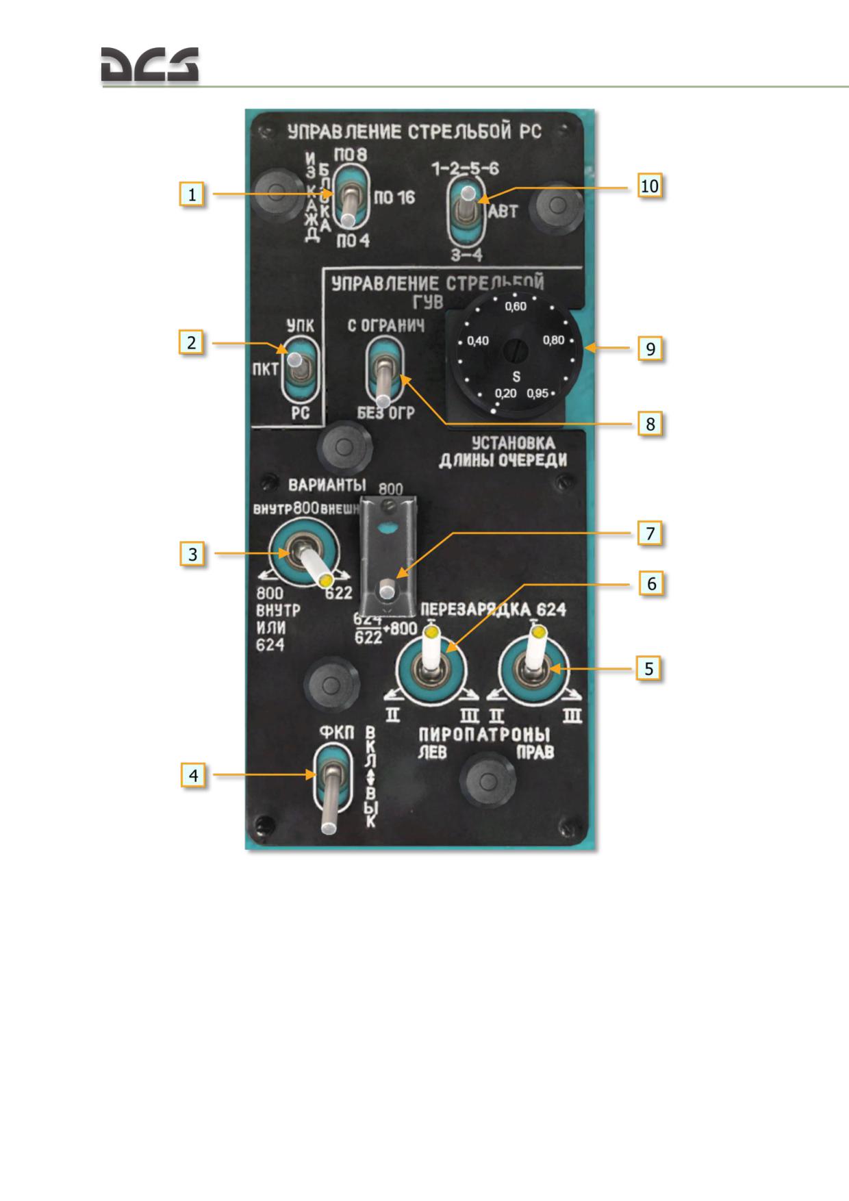
Fig. 11.6. Pilot's lower weapons control panel.
1. Rockets Quantity switch to control selection
6. Charging switch for reloading the left-side
of 4, 8, or 16 rockets to be fired per pod
YakB-12.7 guns (three cartridges for guns I,
2. Weapon Selector switch: UPK (УПК) - PKT
II, III)
(ПКТ) - RKT (РС).
7. GUV (ГУВ) payload selector switch
3.GUV (ГУВ) fire selector switch
8. GUV (ГУВ) fire burst cutoff switch
4. Gun camera switch (not implemented)
9. GUV (ГУВ) burst length switch
5. Charging switch for reloading the right-side
10. Rocket Station Selector switch
YakB-12.7 guns (three cartridges for guns I,
II, III)
310
1. Rockets Quantity switch: ПО8 - ПО16 - ПО4 (8 - 16 - 4). Controls the
number of rockets fired from each rocket launcher while the Weapons Fire switch
is held down. For example if two pods are loaded, set the switch to "ПО4" to fire
up to 8 rockets (4 per launcher).
2. Weapon Selector switch: УПК - ПКТ - РС (UPK - PKT - RKT). Used to
select the weapon for fire when the Weapons Fire switch is pressed (except for
GUV, which has a separate selector on the copilot's weapons configuration panel).
УПК (UPK) - firing of UPK-23-250 gun pods. ПКТ (PKT) - firing of the nose-
mounted PKT machine gun when in stow mode (not implemented). РС (RKT) -
firing of unguided rockets from the B8V20-A launchers (pods).
3. GUV (ГУВ) Fire Selector switch: ВНУТР 800 ВНЕШ - 800 ВНУТР ИЛИ
624 - 622. The ВНУТР 800 ВНЕШ position is used to select grenades for fire
from stations 1 and 6. The 800 ВНУТР ИЛИ 624 position is used to select
grenades or the YakB-12.7 machines gun for fire on stations 2 and 5. The 622
position is used to select the GShG-7.62 machines guns for fire on stations 2 and
5.
This switch is used in conjunction with the GUV Payload Selector switch. All possible
switch combinations are reviewed below.
4. Gun Camera switch. Enables the gun camera, which records whenever the
Weapons Fire switch is pressed on the Aircraft Commander’s Cyclic control
handle.
5. YakB-12.7 Charging switch (right). Used to reload the YakB-12.7 gun pod
machine guns in case of a jam. Must be placed to the "I" position prior to firing.
6. YakB-12.7 Charging switch (left). Used to reload the YakB-12.7 gun pod
machine guns in case of a jam. Must be placed to the "I" position prior to firing.
7. GUV Payload Selector switch: 800 - 624/622+800. Set to 800 when only
grenade launchers are loaded (stations 1, 2, 3, 4, 5, 6). Set to 624/622+800
when mixed payload is carried for correct fire selection: stations 1, 6 grenade
launchers, 2, 5 machine gun pods.
This switch is operated in conjunction with the GUV Fire Selector switch. All possible
switch combinations are reviewed below.
8. GUV Cuttoff switch. When set to OFF (down), the GUV containers will fire as
long as the trigger switch is held down. When set to ON (up), the GUV containers
will fire in burst lengths as set by the BURST knob.
9. GUV BURST knob. Sets the burst length for GUV containers in seconds:
short and medium burst length is set by setting the knob to 0.25 and 0.6
seconds, respectively.
when employing the grenade launcher, setting the knob between 0.25 and
1.00 approximately equals the number of round expanded multiplied by a
factor of 10.
when employing the YakB 12.7 mm gun, setting the knob to 0.25
corresponds to approximately 15 - 18 rounds per burst; 0.6 to 40 - 42
rounds per burst
when employing the 7.62 mm gun, setting the knob to 0.25 corresponds
to approximately 20 - 25 rounds per burst; 0.6 to 50 - 60 rounds.
10. Rocket Station Select switch: 1-2-5-6 - AUTO - 3-4. Used to select rocket
stations for fire.
When set to "1-2-5-6" rockets are fired in a sequence of:
a. Rocket 1 from launchers 1 and 6
b. 0.025 interval
c. Rocket 1 from launcher 2 and 5
Rockets are fired from each launcher with an interval of 0.05 seconds.
When set to AUTO, rockets are first fired from launchers on stations 1, 2, 5, 6. Once
these stations are expended, the system automatically switches to launchers on
stations 3, 4.
11.4. Bombs control panel
The bombs control panel is designed to indicate weapon stations loaded status,
control tactical and emergency release of weapons, and arm the GUV firing circuits.
The panel is installed on the canopy frame on the right side of the cockpit for use by
the copilot (Fig. 11.7).
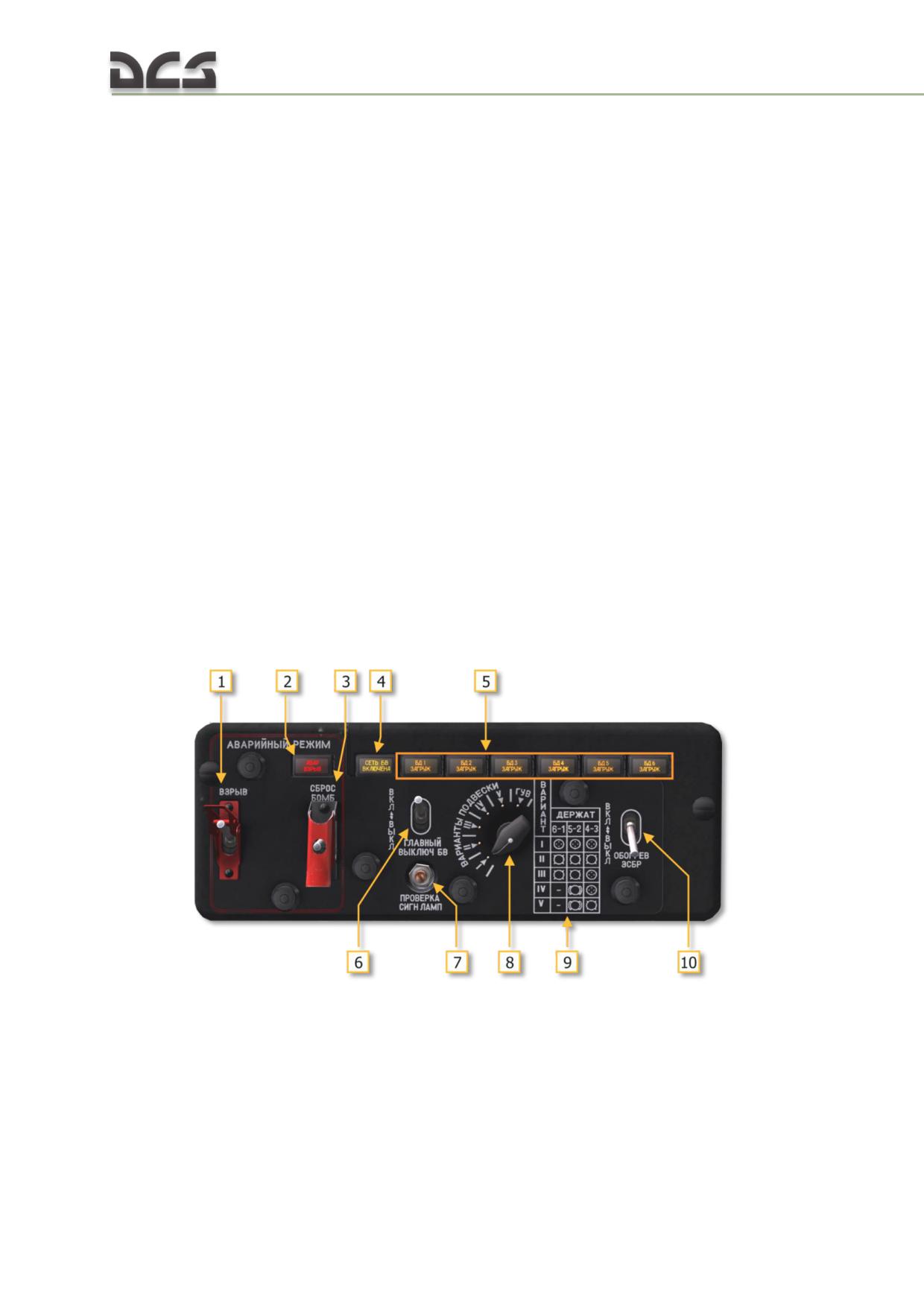
Fig. 11.7. Copilot's payload configuration panel
1.Jettison ARMED switch
6. BOMBS MASTER switch (in EN-cockpit of
2.Jettison ARMED light
the Game - MAIN BOMBS)
3.Jettison switch
7. Lamp test button
4.Bombs cuircuit ON light
8.Payload profile selector
5. Stations loaded lights (6)
9.Paload profile guide
10.ESBR heating switch (not implemented)
312
1. Jettison ARMED switch. When set to ARMED (up), jettisoned bombs are armed
for detonation upon impact.
2. Jettison ARMED light. Indicates bombs are armed to detonate upon impact if
jettisoned. Illuminates if jettison ARMED switch is set to ARMED (up).
3. Jettison switch. Used to jettison bombs.
4. BOMBS CIRCUIT ON light. Indicates bomb release circuits are switched on.
Illuminates if BOMBS MASTER switch is set to ON (up).
5. Stations loaded lights. Illuminate to indicate stations loaded with bombs when
the BOMBS MASTER switch is to ON (up).
6. BOMBS MASTER switch. Energizes the bombs release circuits when set to ON
(up).
7. Lamp test button. Tests the lights installed on the payload configuration panel.
8. Payload profile selector. Five-position selector is set to correspond to current
payload and used to control the release/jettison of stores only from stations
loaded with bombs (primarily intended to prevent accidental release/jettison of
stores other than bombs).
I. All rockets: all bomb release circuits are energized, however no bombs
(or any other stores) will actually release when any of the three bomb
release triggers are pressed (two KSB-49 remote triggers or the OPB-1R
optical bombing sight trigger).
N O T E . The release system does not actually “know” what types are stores are loaded on the
stations, it is only supplied the position of the payload profile selector switch (8).
II. All bombs: pressing any bomb release trigger will sequentially release
all stores from all stations starting with station 6 with the first press of the
release trigger.
III. 4 bombs + 2 rocket launchers: pressing any bomb release trigger will
sequentially release any stores from stations 6-1-5-2 starting with the first
press of the release trigger.
IV. 2 heavy bombs + 2 rocket launchers: pressing any bomb release
trigger sequentially release any stores from stations 5-2 starting with the
first press of the release trigger.
V. 2 heavy bombs + 2 standard bombs: pressing any bomb release trigger
will sequentially release any stores from stations 5-2-4-3 starting with the
first press of the release trigger.
N O T E . The “-“ (dash) mark on positions IV and V indicates that no release signal will be supplied
to the corresponding station.
The “heavy bomb” symbol indicates a heavy or incindeary bomb, however
this does not affect the jettison as any store type (including rocket
launcher, UPK or GUV pod) will be successfully released from stations 5
and 2 in these payload profile selector positions.
ГУВ (GUV). Energizes the GUV firing circuits. In this position all other fire/release
circuits are blocked and no other weapon system can be fired or released with the
exception of an emergency release by the pilot’s emergency jettison switch.
9. Payload profile guide. Payload profile index guide for profile setting.
10. ESBR heating switch. Set the electrical release control system heating
on/off for operations in cold (negative) temperatures (not implemented).
11.5. ЭСБР-3П/А (ESBR-3P/A) Electrical release control box
The ESBR electrical release control box is located below the copilot’s instrument
panel. The ESBR controls sequential single or paired release of bombs and provides
for station selection for release of any store.
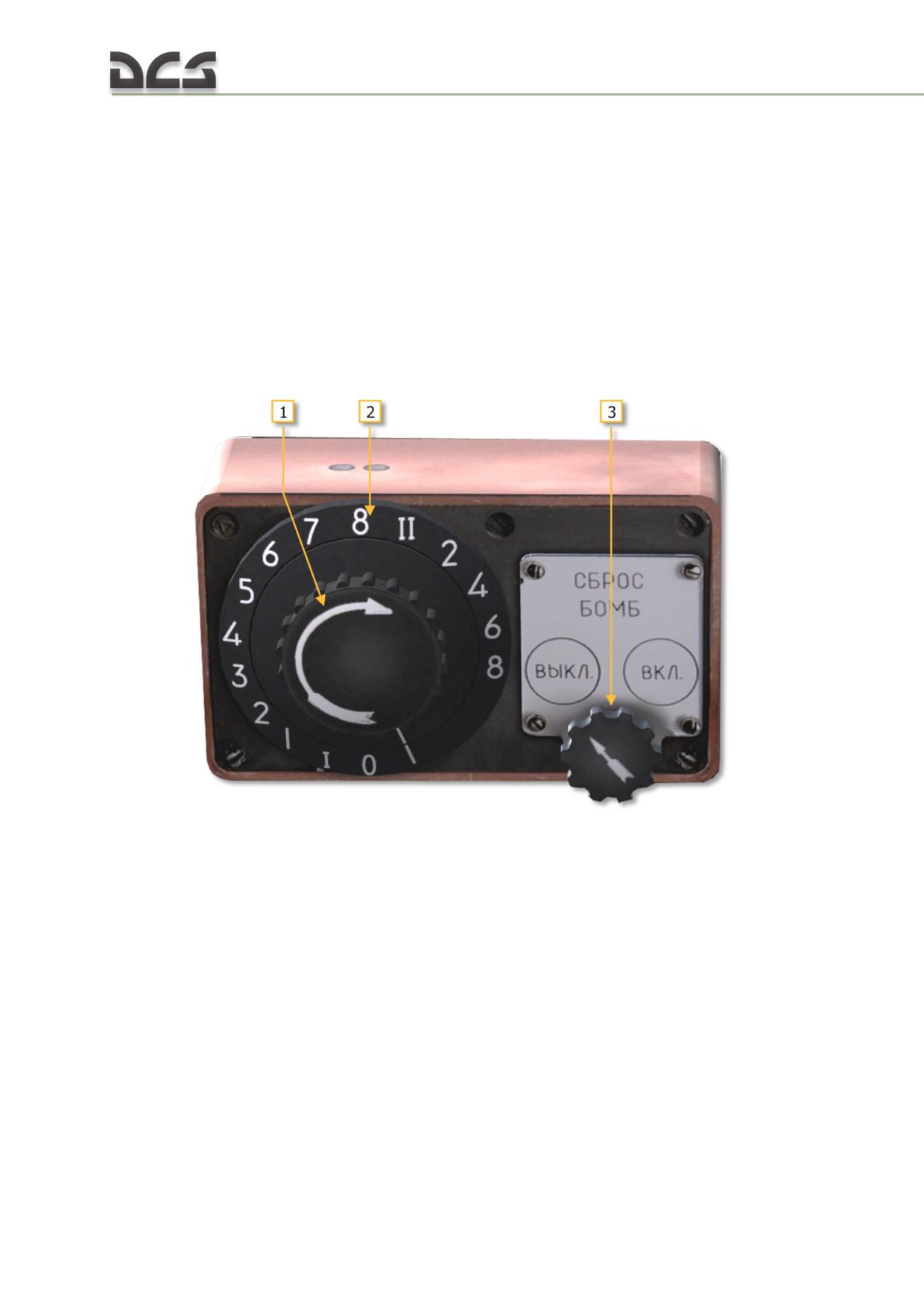
Fig. 11.8. ESBR control box
1. Signal setting knob
21. ESBR power swtich
2. Signal setting index plate
1. Signal setting knob. Used to set single or pairs release mode or select the
release number in the release sequence.
2. Signal setting index plate. The index plate consists of a series of numerical
indexes that indicate either single (“I”) or pairs (“II”) release mode setting as well
as Arabic numerals that indicate the current release number in the release
sequence.
3. ESBR power switch. Connects the electrical release control system to the bomb
release circuits.
When releasing bombs, all of the required circuit breakers must be switched ON, the
BOMBS MASTER switch set ON (up), the desired payload profile set, the ESBR signal
314
setting knob (1) set to the desired position for release and the ESBR power switch
(3) set to “ВКЛ” (ON) (right).
When the signal setting knob is set to “\” or “0”, no stores will be released. These
positions are used to system ground tests.
POSITION I: In position “I”, the ESBR commands the weapons control system for
single bomb release in sequence from stations 6-1-5-2-4-3 (if payload profile “II” is
set on the bombs control panel). However if desired, the ESBR can be used to
manually select the desired station for release. For example, to select station 3 for
release:
turn off the ESBR by setting the ESBR power switch to “ВЫКЛ” (OFF)
(left).
set profile “II” on the bombs control panel (profile “V” will work as well,
however this will alter the subsequent procedure)
set the signal setting knob on the ESBR control box to “5”
When the ESBR is turned on with the signal setting knob set to “5”, the next press of
the bomb release trigger will release the store from the sixth station in the release
sequence, i.e. station 3 given that it is preceded by stations 6, 1, 5, 2, 4 in the
release sequence.
When the ESBR is turned on and profile “II” is set on the bombs control panel,
rotating the signal setting knob past the “I” position will result in automatic release
(without pressing the bomb release trigger) from the consecutive station(s) in the
release sequence with each progressive setting of the knob.
POSITION II: In position “II”, the ESBR commands the weapons control system for
paired bombs release in sequence from stations 6+1, 5+2, 4+3 (if payload profile
“II” is set on the bombs control panel). As with single release, the ESBR allows for
manual station selection for paired release.
If profiles “IV” and “V” are set on the bombs control panel (and all relevant
components required for stores release are enabled), a first press of the bombs
release trigger will release stores from station 5 (or 5+2 if the ESBR is set to position
“II”). I.e. in these payload profiles, release commands are not supplied to stations 6
and 1.
11.6. PKV collimating Sight
The PKV collimating sight (Fig. 11.9) is used to aid with visual target ranging and
weapons aiming using target size methodology when employing the nose mounted
PKT machine gun, external gun and cannon systems, rockets, and bombs.
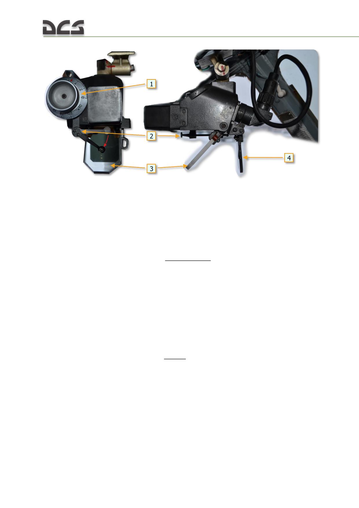
Fig. 11.9. PKV collimating sight (front and side view)
1. Sight elevation knob
3. Reflector glass
2. Mechanical ring sight (stowable)
4. Sun filter glass (stowable)
The sight reticle Fig. 11.10 is turned on by the “СИГНАЛИЗАЦИЯ” (INDICATION)
circuit breaker.
In general, the target range can be defined by the formula
bt
Dt =
2tg(0.5ψt-deg)
where:
Dt = target range
bt = apparent target size (in meters)
tg
= tangent of angle math.function
ψt-deg= target current angular size (in degree)
Target range is determined using the PKV reticle according to the following formula:
bt
Dt =
× 1000
ψt-mils
where:
ψt-mils= target current angular size (in mils as viewed in the reticle)
For example, an object 100 meters in width will be 100 mils across in the reticle at a
range of 1000 meters.
316
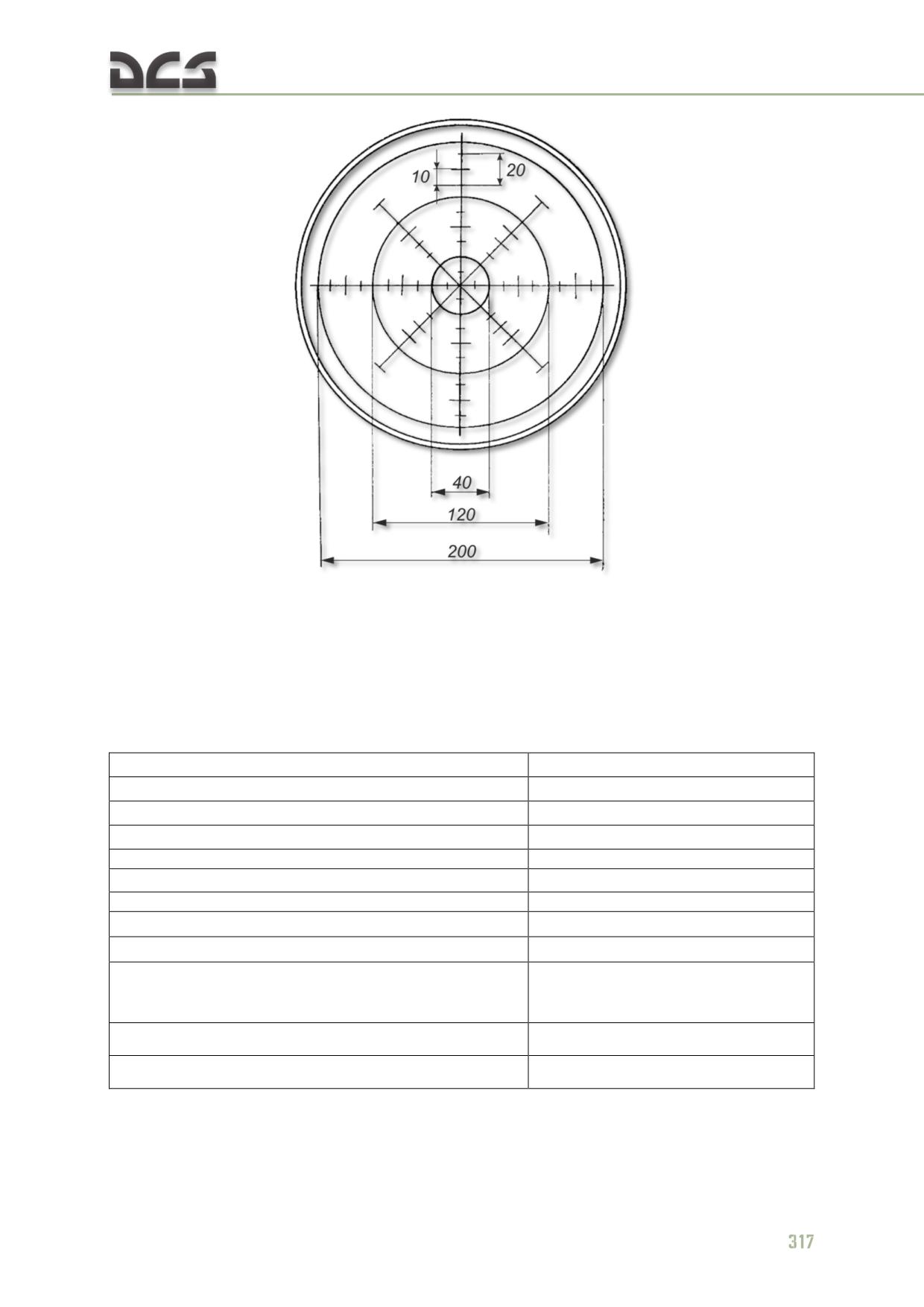
Fig. 11.10. PKV reticle pattern with element sizes in mils
The sight is installed on a bracket assembly on the left side of the cockpit ahead of
the pilot’s head position. To use the sight, the pilot must raise the seat by 15 - 20
cm.
PKV technical specifications: Table 11.1
Table 11.1
Reticle ring size:
Size (mils)
inner
20
middle
60
outer
100
Reticle graduation
10
Elevation knob numerical marking
each 20
Elevation knob graduation
2
Elevation knob large hash graduation
4
Elevation angle range
0 - 200 (0 - 11.5°)
PKV line of sight relative to helicopter water line (sight
57.5 (up)
elevation set to 0)
Elevation knob red index corresponding to (mils)
52.4
Overall weight
1.8 kg
The elevation angle of the sight is set by manipulating the reflector glass using the
elevation knob. Aim is accomplished by placing the sight reticle over the target.
The hash marks of the reticle allow for simple range estimation for targets of known
(approximated) apparent size.
The sight is equipped with a stowable reserve mechanical ring sight in case the
optical system is inoperable.
The “ПОДСВЕТ ПРИЦЕЛА” (SIGHT DIMMER) rheostat on the pilot’s upper weapons
control panel control reticle brightness. A stowable brightness filter glass is available
for use in case of bright backg2round (such as near direct sunlight).
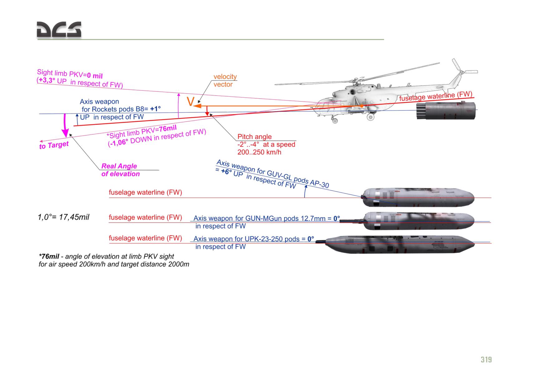
The sight elevation angle is determined by projectile gravity fall, helicopter pitch
angle, and particular weapon system’s installed elevation angle relative to the
helicopter water line (WL). As such, the sight elevation angle is the angle between
the projectile throw elevation and the line of sight to the target (Fig. 11.11).
Sight elevation angles are recalculated for a variety of standard target ranges,
helicopter airspeeds, flight profiles (level flight or dive) for each available weapon
system. Sight elevation charts are provided in the Combat Employment chapter.
318
DIGITAL COMBAT SIMULATOR Mi-8МТV2
Fig. 11.11. Elevation angles relevant to weapons employment using the PKV collimating sight.
DIGITAL COMBAT SIMULATOR Mi-8МТV2
11.7. Weapons fire and bomb release switches
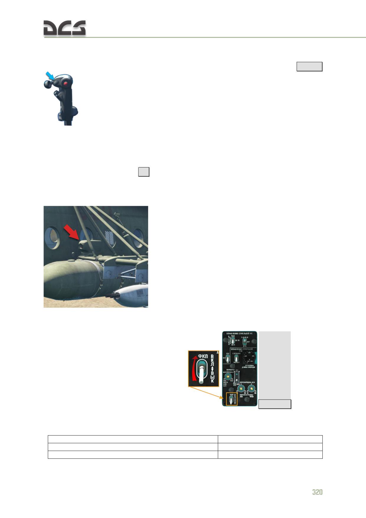
The WEAPONS FIRE switches installed on both cyclic control sticks
[Space]
are used to employ all weapon systems, except release of bombs.
Bomb (or any other external store) release switches are available on the OPB-1r
optical bombing sight (not implemented) and two KSB-49 remote bomb release
triggers (one for the pilot and copilot located to the left and right of the respective
instrument panels), Fig. 11.1, 5, 10. Mouse can not be used for these buttons, only
key commands are available
[B]
11.8. AKS-2 gun camera
The gun camera is installed on the left special hardpoint and can not be jettisoned.
It is used to photo-control how well pilot aims at a
target.
The gun camera consists of device itself and the ФКП (GUN CAMERA) circuit breaker
on the pilot’s lower armament control panel
[RAlt + C]
Main data of the AKS-2, Table 11.2.
Table 11.2
Parameter
Value
shooting rate
24 or 48 fps
open sector of the obturator (device, preventing
120°
glares from the sun)
frame size
16 х 22 мм
used film
35 mm (perforated)
shutter speed:
at a frame rate of 24 fps
1/50 sec
at a frame rate of 48 fps
1/100 sec
film length in the cartridge
60 m
duration of continuous shooting:
at a frame rate of 24 fps
2 min.12 sec.
at a frame rate of 48 fps
1 min. 6 sec.
focus distance
135 mm
max consumed current
12 А
power supply
27 V
size
474х139х210 mm
Weight
9,1 kg
In the game a frame rate of 24 fps is implemented.
NOTE: Optical axis of this device is parallel to the fuselage’s centerline, therefore center position of
the frame, relative to the target, taken by the gun camera, will be different from one, relative to the
PKV center on a screenshot, if aiming angle on the PKV’s sight elevation knob is different from 57.5
mils.
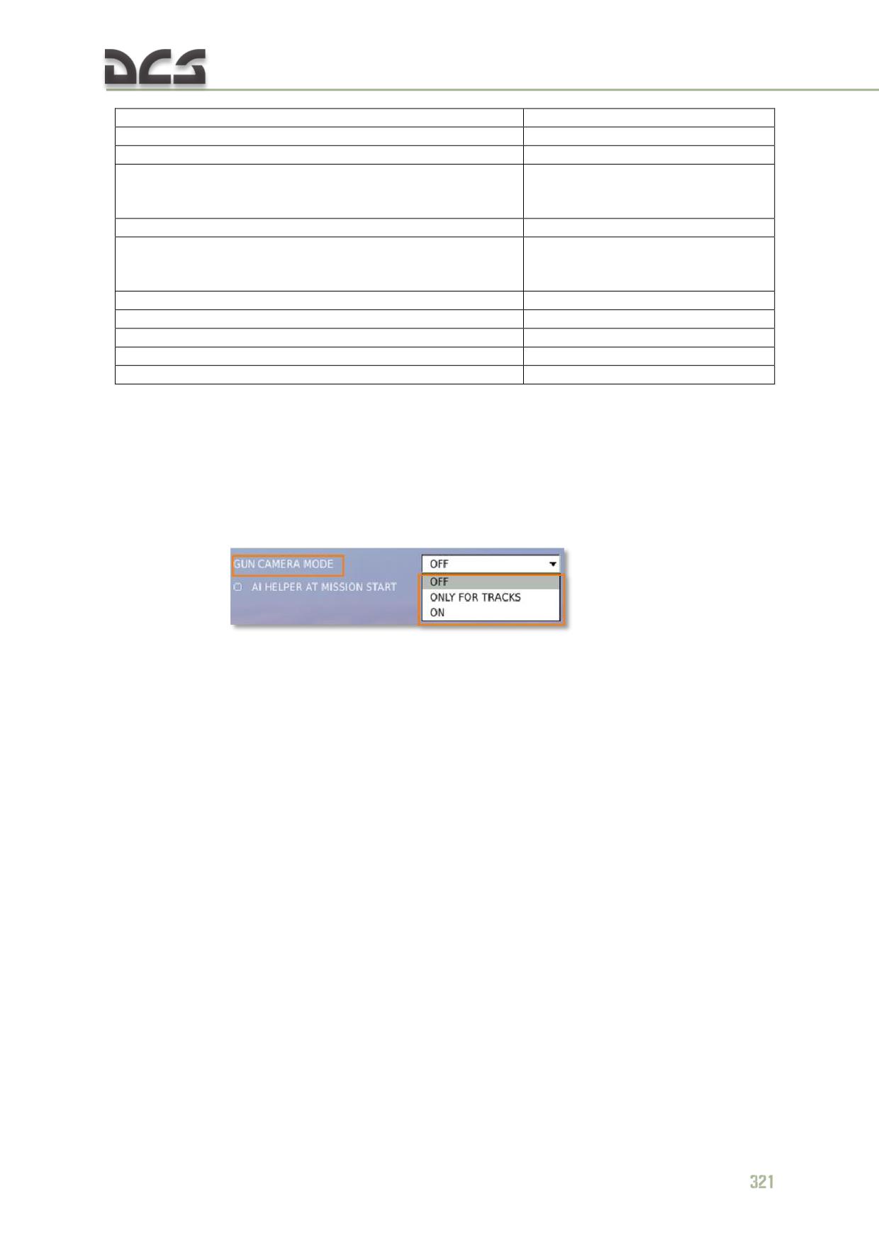
Photos, taken by the gun camera can be seen during the game or track replay. To do
that, player must select one of the available GUN CAMERA MODE options in the
game settings:
OFF - disabled;
ONLY FOR TRACKS - photos will be shown during tracks only;
ON - photos will be shown immediately, while shooting (can cause small
fps drop).
All moments, whenever player pressed any of the combat triggers on cyclics, will be
shown as “”photos”, made by the AKS-2 gun camera:
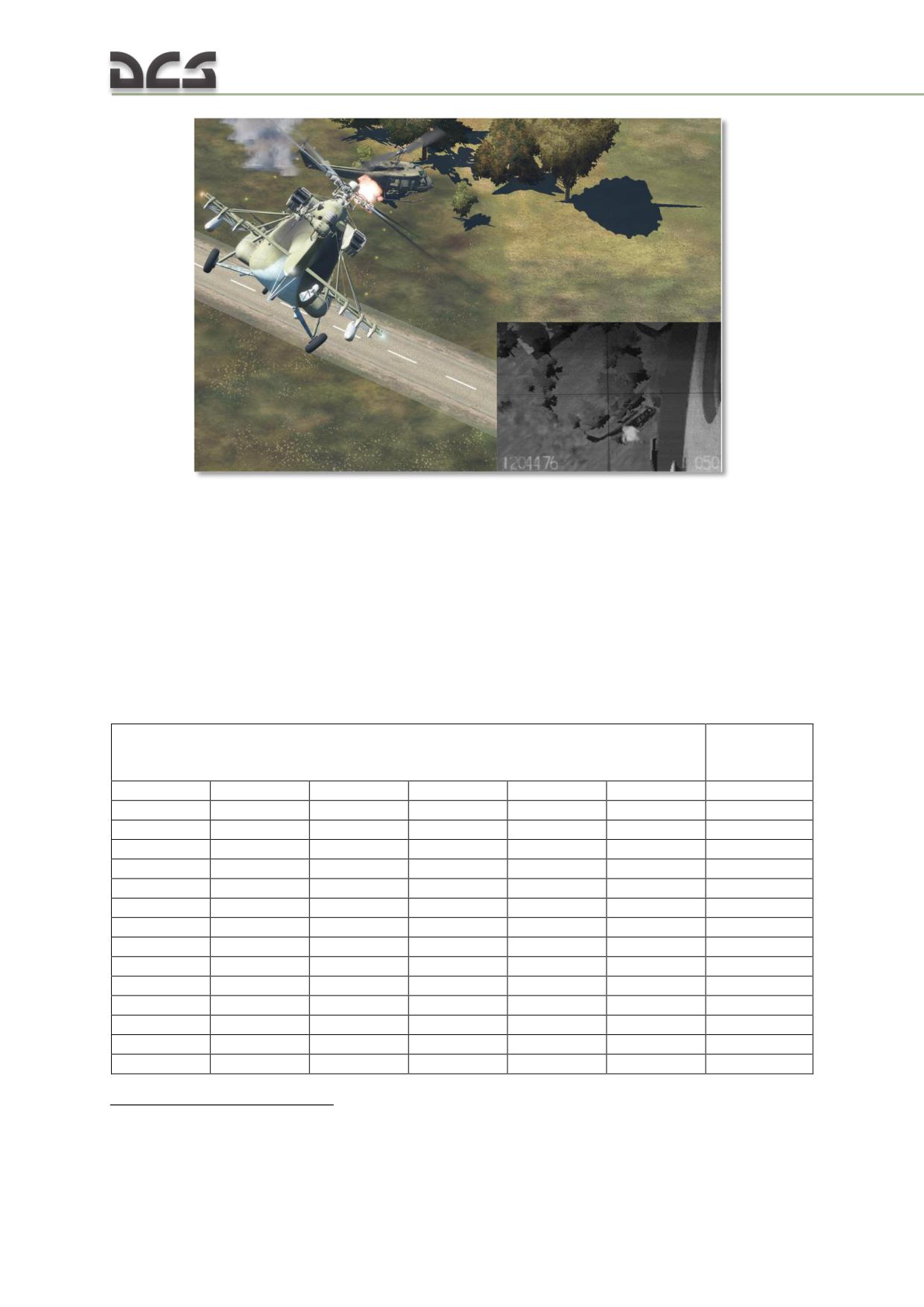
Fig. 11.12. Position and example of the photo, taken by the AKS-2 gun camera
11.9. Weapon systems
The Mi-8MTV2 weapons control system includes a number of sub-systems which
make it possible to employ a variety of weapon systems in mixed payload
configurations.
Mi-8MTV2 Payload configurations (profiles)
Available stores for each external weapon station are listed in Table 11.3.
Table 11.3
In service
Available loads for weapons stations #1 - 6 for combat employment
with RF
military
1
2
3
4
5
6
–
B8
B8
B8
B8
-
yes
B8
B8
B8
B8
B8
B8
no 1
–
UPK
B8
B8
UPK
-
yes
B8
UPK
B8
B8
UPK
B8
no
–
AB-250,100
B8
B8
AB-250,100
-
yes
AB-250,100
AB-250,100
B8
B8
AB-250,100
AB-250,100
no
AB-250,100
AB-250,100
AB-250,100
AB-250,100
AB-250,100
AB-250,100
yes
–
АB-500
AB-250,100
AB-250,100
А-500
-
yes
GUV (GD)
GUV (MG)
Б8
Б8
GUV (MG)
GUV (GD)
no
GUV (GD)
GUV (MG)
-
-
GUV (MG)
GUV (GD)
yes
GUV (GD)
GUV (GD)
-
-
GUV (GD)
GUV (GD)
yes
–
VSM
VSM
VSM
VSM
-
yes
–
UPK
VSM
VSM
UPK
-
yes
GUV (GD)
GUV (GD)
VSM
VSM
GUV (GD)
GUV (GD)
yes
1 Not in service for administrative reasons, but technically supported by the Mi-8MTV2 weapons control
system.
322
GUV (GD)
GUV (MG)
VSM
VSM
GUV (MG)
GUV (GD)
no
Chart legend:
B8: B8V20-A rocket launcher with 20 80 mm S-8 unguided rockets;
UPK: UPK-23-250 cannon pod system;
AB-250, 100: 250 kg, 100 kg free-fall bomb;
GUV (MG): GUV-8700 pod with 1 x 12.7 mm, 2 x 7.62 mm machine guns;
GUV (GD): GUV-8700 pod with AG-17A automatic grenade launcher;
VSM: mine container, part of the VSM-1 minelayin system (not implemented in simulation).
In any variants, the 12.7-mm KORD machine gun, installed in the cargo cabin
doorway and the 7.62-mm PKT machine gun, installed in the hatch of the right cargo
bay door, can be used.
11.9.1. Unguided rocket system
Purpose
The unguided rocket system is designed to be employed against column or area
(group) targets consisting of unarmored or lightly armored ground units. The Mi-
8MTV2 is armed with B8V20-A rocket launchers equipped with 20 S-8 80 mm
rockets. Previous generation UB-32A-24 launchers equipped with S-5 57 mm rockets
are no longer in service.
Components
Used with the B8V20-A launchers, the unguided rocket system includes:
four 20-tube B8V20-A rocket launchers (Fig.11.13) (the weapons control
system support up to 6 launchers)
80 S-8 unguided rockets of various modifications (S-8M, S-8AS, S-8B, S-
8KO, S-8OF) (the weapons control system supports up to 120 S-8 type
rockets)
four ПУС-36-71 (PUS-36-71) fire control devices (FCU) integrated into the
external weapon stations #1, 3, 4, 6
control interfaces
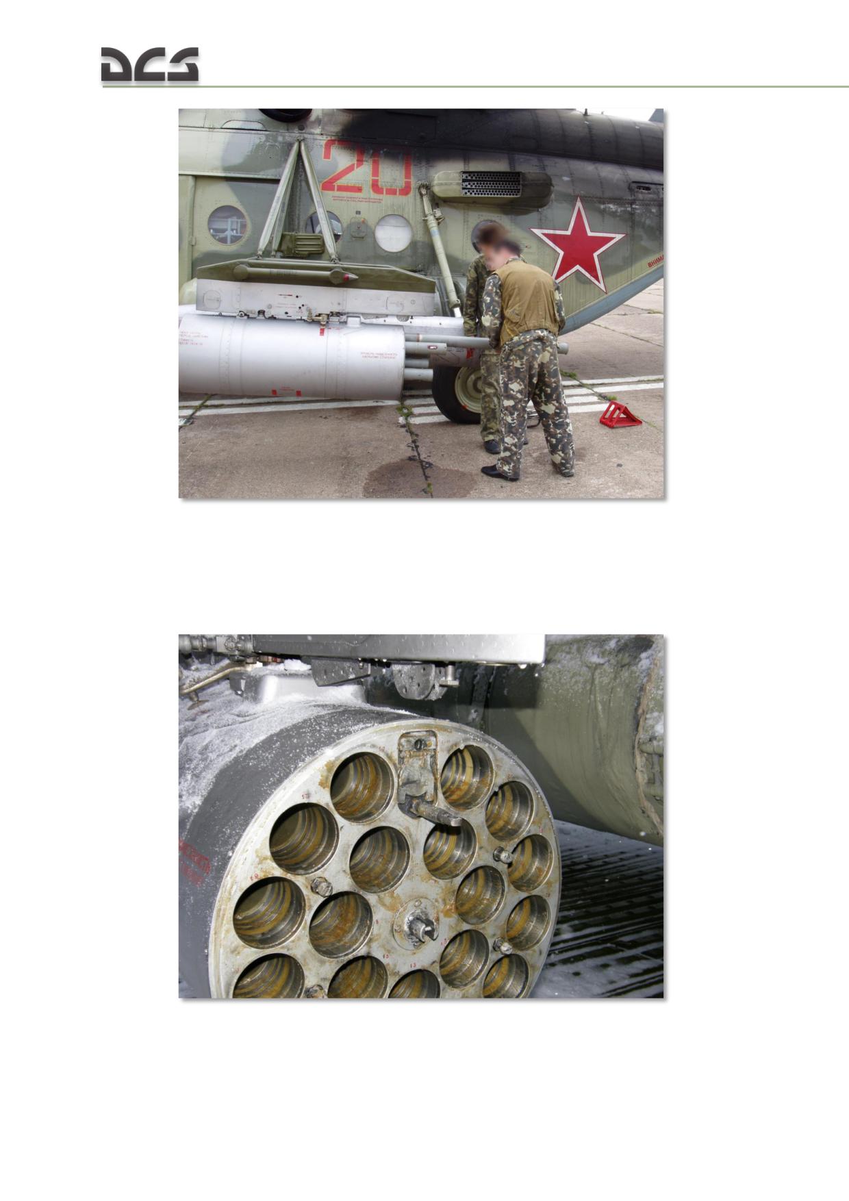
Fig.11.13. Loading of a B8V20-A rocket launcher on an Mi-8MTV5 helicopter.
Description
The B8V20-A rocket launcher serves as a container/casing with 20 integrated launch
tubes used to house and launch S-8 unguided rockets (Fig.11.14).
Fig.11.14.B8V20-A launcher tubes as seen from the rear.
324
The rocket launchers are attached to the weapon stations via suspension locks. The
weight of an unloaded launcher is 100 kg. The weight of a loaded launcher is 332 -
405 kg depending on rocket modification.
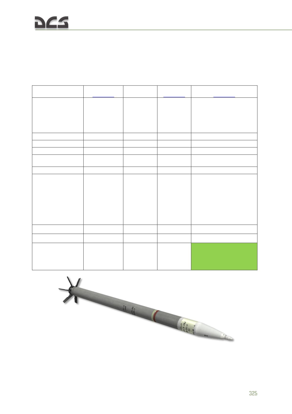
The technical specifications of S-8 rocket modifications available in DCS: Mi-8MTV2
Magnificent Eight are provided below in Table 11.4.
Table 11.4
S-8KOM
S-8TsM
S-8OFP2
Rocket modification
S-8ОМ
Fig. 11.15
Fig. 11.16
Fig. 11.17
Destruction of
Destruction of troops
lightly/medium
Target
(explosive and
Purpose
Illumination
armored units
designation
fragmentation effects) and
and troops
lightly armored units
Diameter, mm
80
80
80
80
Length, mm
1570
1632
1632
1570
Launch mass, kg
11.3
12.1
11.1
16.7
Warhead/combat
3.6
4.1
4.1
9.5
section mass, kg
HE mass , kg
0.9
***
***
2.9
Illumination
flares,
Explosive fragmentation,
Dual-purpose
ignition 17
penetrating (delayed HE
(shaped
Warhead type
sec after
smoke
detonation),
charge/
launch,
1000 - 2000 fragments of 3
fragmentation)
duration 40
- 6 g
sec
Peak velocity, m/s
Up to 650
Up to 545
670
Up to 450
Muzzle velocity, m/s
37 - 52
37 - 52
37 - 52
37 - 52
Targeting elevation
angle (mils) at 2000
76
***
76
98
m, level flight,
V=200 кph
Fig. 11.15. S-8КОМ rocket
Fig. 11.16. S-8TsM rocket
Fig. 11.17. S-8OFP2 rocket
Ripple and salvo firing of rockets from multiple stations in various payload profiles is
accomplished by use of ПУС-36-71 (PUS-36-71) fire control devices (FCU), which are
integrated into the weapons stations. FCUs process and supply electric signals to the
launch tubes of the B8V20-A launchers to command rocket launch. FCU-1 controls
the launchers on stations #1-2; FCU-3 controls the launcher on station #3; FCU-4
controls the launcher on station #4; FCU-6 controls the launchers on stations #5-6.
Attached to the weapons stations, the launchers are elevated 1° up from the
helicopter water line.
Rocket employment procedures are described in the To deploy rockets from the
B8V20 launcher chapter.
11.9.2. UPK CANNON SYSTEM
Purpose
The UPK podded cannon system is designed to be employed against individual and
group unarmored or lightly armored ground targets within visual contact in day and
night time conditions.
Components
The УКП-23-250 (UPK-23-250) cannon pods are equipped with GSh-23L 23 mm twin
barrel cannon.
The podded cannon system includes the following components:
326
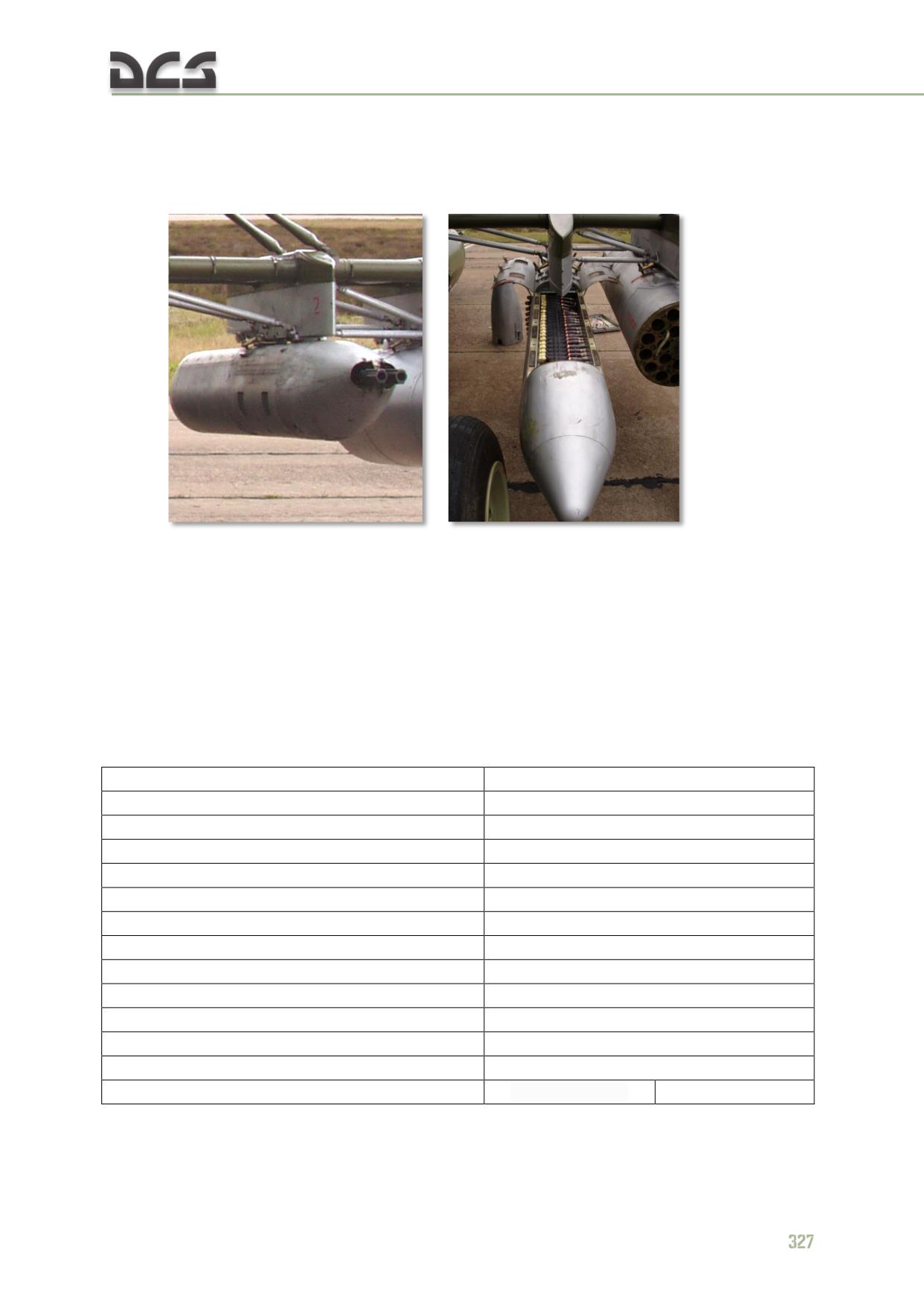
two UPK-23-250 cannon pods equipped with the GSh-23L cannon (Fig.
11.18)
two weapons stations (#2, 5) supporting UPK-23-250 cannon pod loading
control interfaces
Fig. 11.18. UPK-23-250
Description
Each UPK pod is loaded with 250 rounds of 23 mm ammunition. The weight of a
loaded UPK pod is 230 kg. The system includes an automatic burst cutoff of 0.16
seconds, during which 8-10 rounds are fired. The burst length cannot be adjusted.
The technical specifications of the GSh-23L cannon employed in the UPK-23-250
cannon system are provided below in Table 11.5.
Table 11.5
Specification
Value
Caliber, m
23
Dimensions, mm:
length
1537
width
165
height
168
Mass, kg
50±1.5
Rate of fire, rounds/min
3000-3400
Muzzle velocity, м/sec
715±15
Recoil impulse, kgf
<2900
Ammunition capacity
250
Max burst length, rounds
10
Thermal capacity, rounds
250
Used cartridges:
HEFI-23-AM-GSH
API-T-23-AM-GSH
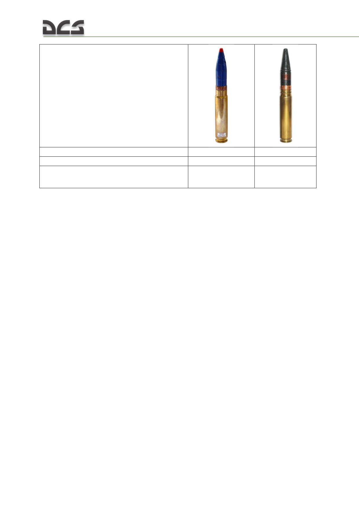
cartridge weight, g
338
340
shell weight, g
184
186
Shell properties
high explosive
armor piercing
fragmentation
incindiary - tracer
incindiary
Aim is accomplished using the PKV collimating sight.
Attached to the weapons stations, the UPK pods are parallel to the helicopter water
line.
Cannon employment procedures are described in the To deploy UPK-23-250 23-mm
gun container chapter.
11.9.3. GUV universal gun or grenade launcher container systems
Purpose
GUV machine gun and grenade launcher podded systems are designed to be
employed against individual and group unarmored or lightly armored ground targets
within visual contact in day and night time conditions.
Components
The GUV gun pod systems include the following components:
GUV-1 (GUV-8700) pod equipped with AG-17A (AP-30) 30 mm “Plamya-A”
automatic grenade launcher (service index 9-A-800) (Fig. 11.19) or single
YakB-12.7 (service index 9-A-624) 12.7 mm machine gun and twin GShG-
7.62 (service index 9-A-622) 7.62 mm machine guns (Fig. 11.20)
four weapons stations (#1, 2, 5, 6) supporting GUV pod loading
control interfaces
328
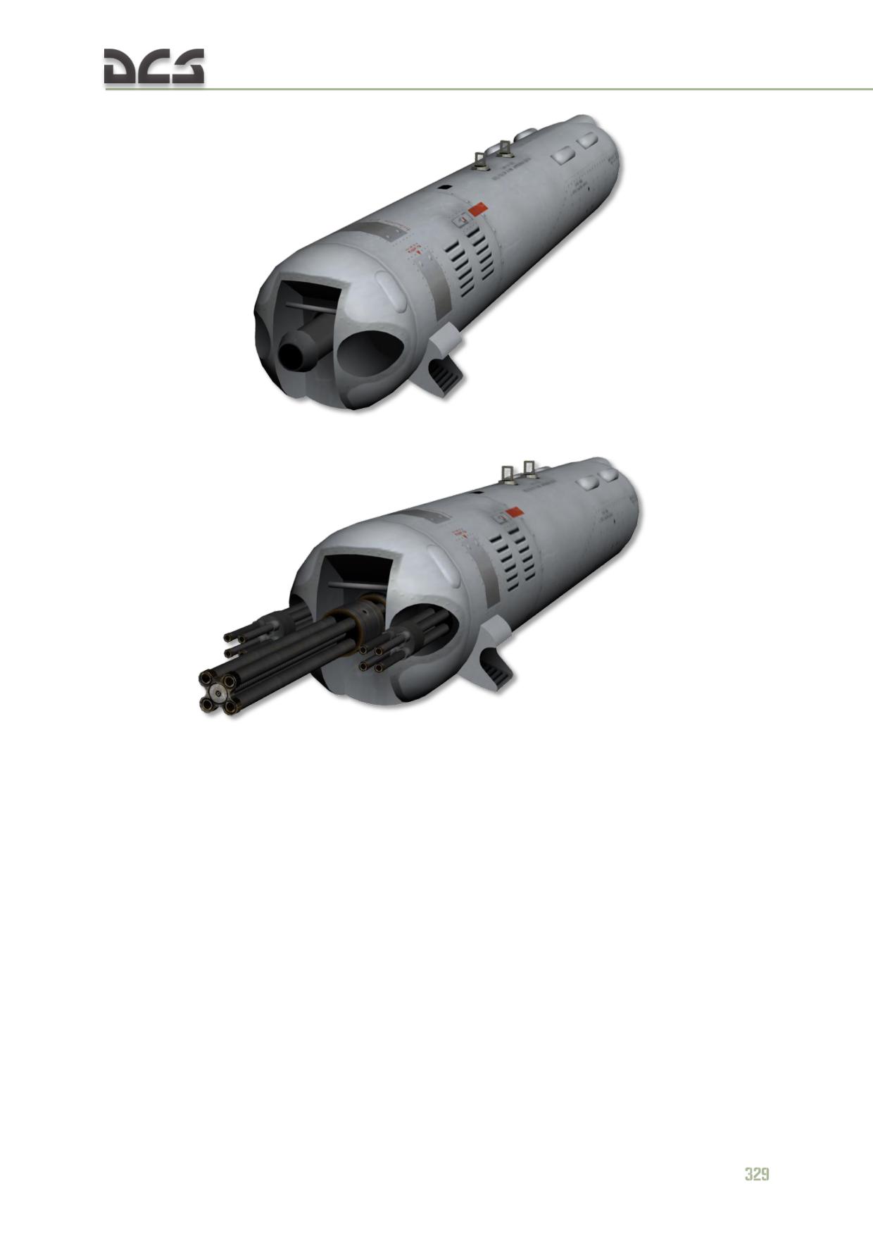
Fig. 11.19. GUV-1 equipped with automatic greande launcher
Fig. 11.20. GUV-1 equipped with machine guns
Description
The grenade launcher variant of the GUV pod system is equipped with the AG-17A
30 mm automatic grenade launcher (“Plamya-A”, AP-30, 9-A-800) (Fig. 11.21).
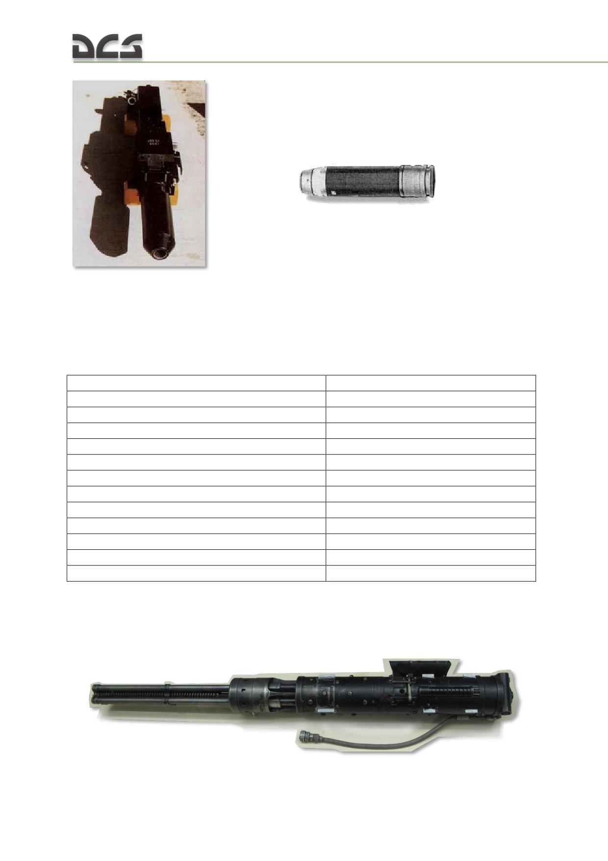
Fig. 11.21. AG-17A ("Plamya-А")
grenade launcher and VOG-17 grenade
munition
The grenade launcher pod is loaded with 300 grenades.
The technical specifications for the AG-17A (AP-30) automatic grenade launcher and
its munition are provided below in Table 11.6
Table 11.6
Specifications
Value
Caliber, m
30
Munition
VOG-17 (VOG-17M)
Mass of grenade launcher, kg
21 - 22
Muzzle velocity, m/s
185
Muzzle energy, J
4791
Firing mode
Continuous (automatic)
Rate of fire
600/min
Practical range
1700
Direct fire range for 2 m target, m
200 - 250
Mass of munition, g
350 / 280 (36 g HE)
Self-destruct time, sec
25 - 27
Kill radius , m
6 - 7
The machine gun variant of the GUV pod system is equipped with a single YakB-12.7
(9-A-624) 12.7 mm machine gun (Fig. 11.22) and two GShG-7.62 (9-A-622) 7.62 mm
machine guns (Fig. 11.23).
Fig. 11.22. YakB-12.7 12.7 mm 4-barrel Gatling gun
330
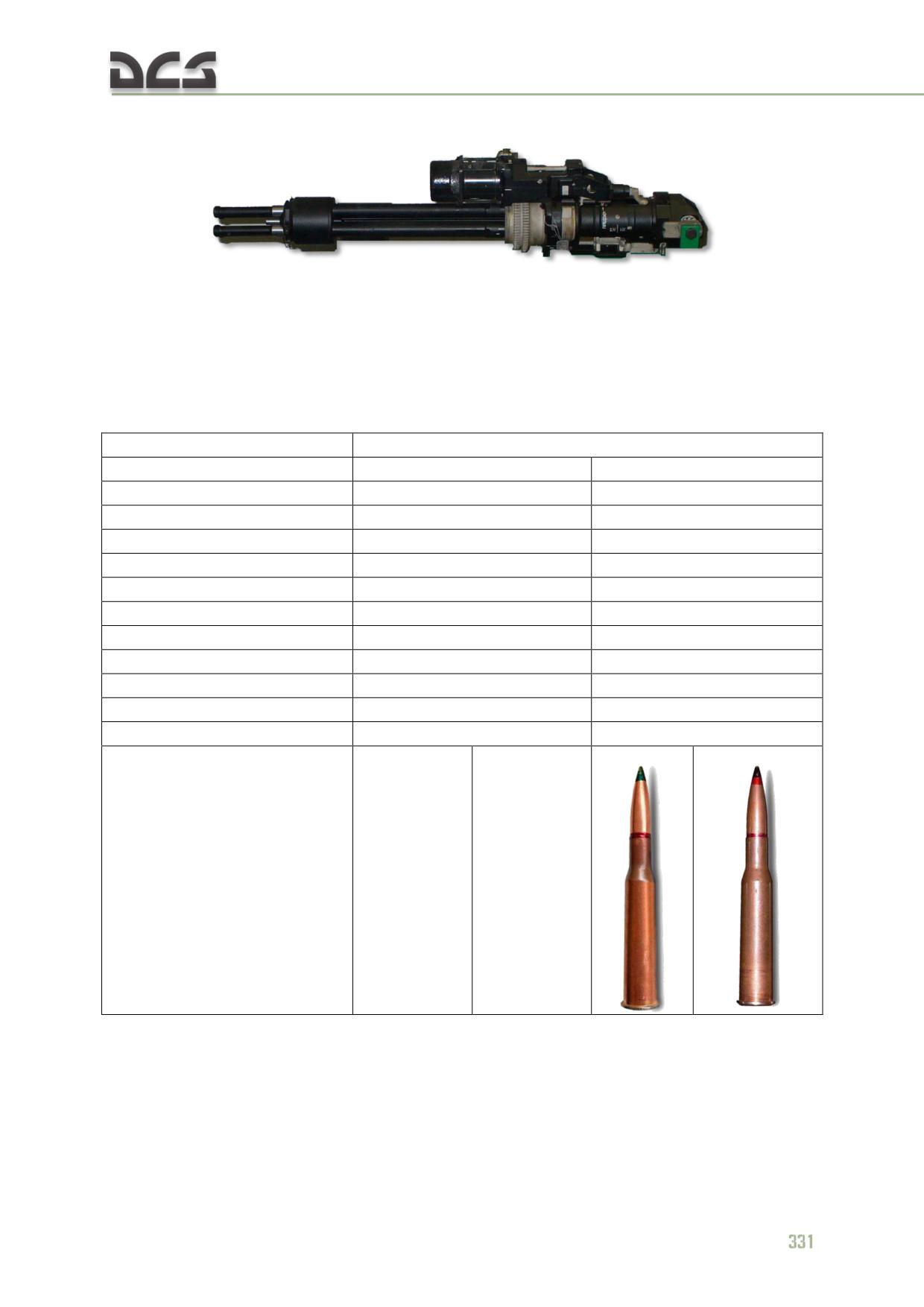
Fig. 11.23. GShG-7.62 7.62 mm 4-barrel Gatling gun
The gun variant of the GUV pod is loaded with 750 rounds of 12.7 mm ammunition
and 3400 rounds of 7.62 mm ammunition.
The technical specifications for the machine guns equipped on the GUV-1 pod system
are provided below in Table 11.7.
Table 11.7
Specifications
Value
Caliber, mm
12.7
7.62
Dimensions, mm:
length
1345
800
width
145
height
190
Mass, kg
45
19
Rate of fire, rounds/min
4000-4500
6000
Muzzle velocity, m/s
810
850
Recoil impulse, kgf
1400
Ammunition capacity, rounds
750
1800
Max burst length, rounds
400
1000
Operational life, rounds
8000
Used cartridges (rounds)
12.7 API-T
12.7 API B-32
7.62 AP-T
7.62 API B-32
BZT-44
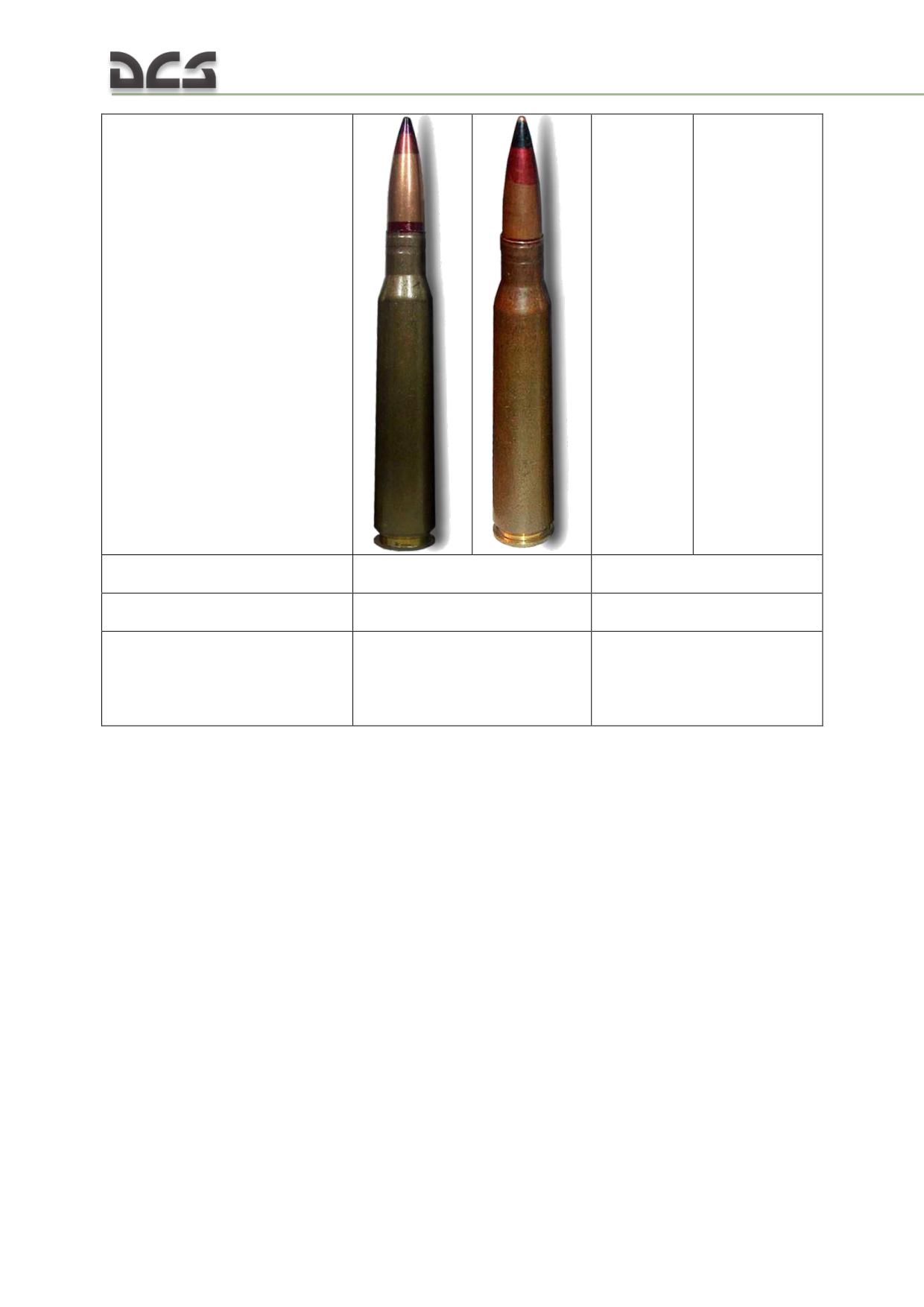
Cartirdge weight, g
128 (BZT-44)
21,6 (AP-T)
133,5 (B-32)
22,9 (B-32)
Bullet weight, g
44 (BZT-44)
9,2 (AP)
48,2 (B-32)
10,4 (B-32)
Bullet properties
BZT-44 (API-T) - armor
AP-T - armor piercing tracer
piercing incindiary tracer
B-32 (API) armor piercing
B-32 (API) armor piercing
incindiary
incindiary
The weight of a loaded machine gun variant of the pod does not exceed 452 kg. The
weight of a loaded grenade launcher variant does not exceed 274 kg.
In the grenade launcher pod is loaded on weapons stations #1, 2, 5, 6 (1, 6 if only
two pods loaded). The machine gun pod is loaded only on stations #2, 5.
The machine gun pods are attached to the weapons station parallel to the helicopter
water line. The grenade launcher elevation is +6° from the water line.
The weapons control system supports simultaneous loading of grenade launcher and
machine gun pod systems. In this case, grenade launcher pods are loaded on
stations #1, 6 while machine gun pods are loaded on stations #2, 5. Employment of
the different pod systems in the same payload configuration must be separate (i.e.
cannot fire grenade launcher and machine gun pods simultaneously).
Limitations
The YakB-12.7-mm gun requires cooling time after expanding
400 rounds of
ammunition as follows:
25 min if OAT is greater than +10°C
332
15 min if OAT is -10°C to +10°C
5 min if OAT is below -10°C
The GShG-7.62 gun requires a 25 minute cooling cycle after expanding 1000 rounds
of ammunition if OAT is under 20°C. If OAT exceeds 20°C, fire past 1000 rounds is
prohibited.
GUV launcher employment procedures are described in the To deploy the 12.7-mm
(7.62-mm) machine guns and 30-mm grenade launchers from GUV-1 chapter.
11.9.4. Weapon, installed in the cargo cabin
Purpose
Weapon, installed in the cargo cabin is fired by the airborne troops at aerial and
ground targets during the flight and on the ground, at any time of the day when a
target is visually observed.
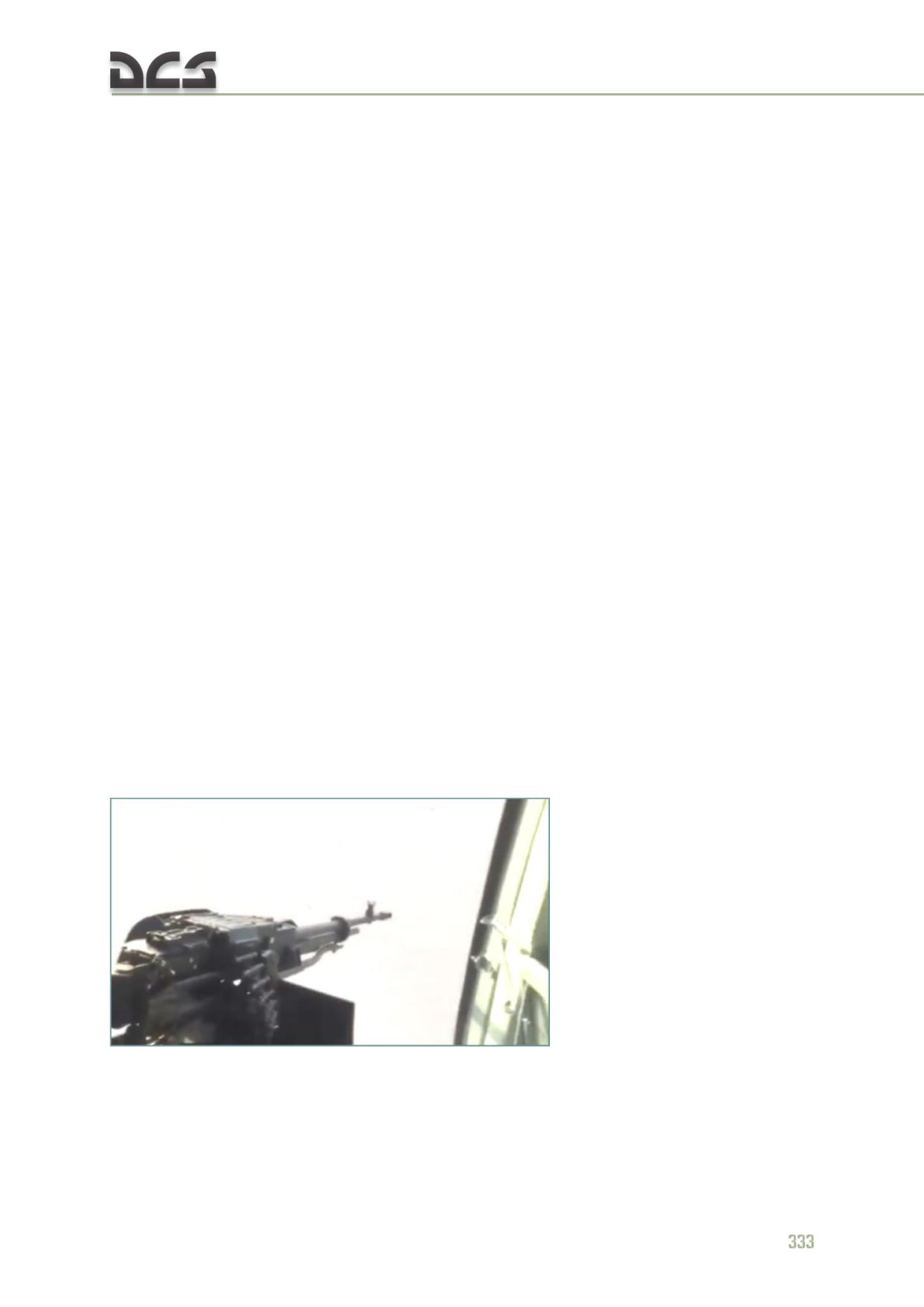
Note. The weapon option, which is described here and used in the game is not the only one, used in
real life.
The following weapon, installed in the helicopter, can be fired simultaneously or
separately:
the 12.7-mm KORD machine gun, installed in the left doorway;
the 7.62-mm PKT machine gun, installed in the hatch of the right cargo
bay door.
Components
The firearms, available for the DCS: Mi-8MTV2 include:
one 12.7-mm KORD machine gun, in the left doorway of the cargo cabin,
mounted on the floor (rack with hinges allows to rotate machine gun in
horizontal and vertical surfaces within a certain range)
;
one tail 7.62-mm PKT tank machine gun with a bag affixed to the gun to
capture ejected casings, installed in the hatch of the right cargo bay door
with help of special hindges.
General description
Main characteristics of both guns are presented in the Table 11.8
Table 11.8
№
Technical characteristic
KORD-12.7 (door)
PKT-7.62 (tail)
1
Caliber, mm
12,7
7.62
2
Shooting rate, rounds per minute
around 600
700
3
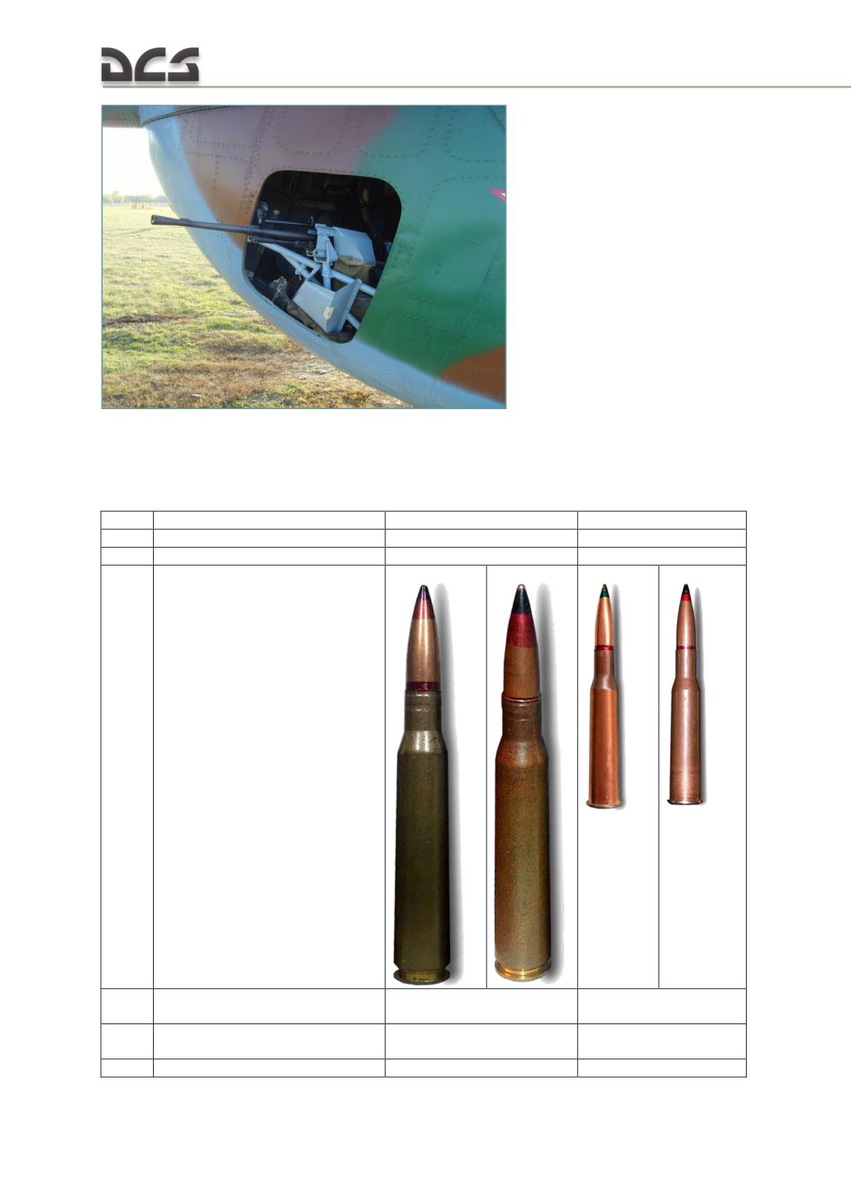
Used cartridges:
12.7 BZT-44
12,7 B-32
7,62 BT
7,62 B-32
4
Cartridge weight, g
128 (BZT-44)
21,6 (BT)
133,5 (B-32)
22,9 (B-32)
5
Bullet weight, g
44 (BZT-44)
9,2 (BT)
48,2 (B-32)
10,4 (B-32)
6
Свойства пули
BZT-44 (API-T) - armor
BT (AP-T) - armor
334
piercing incendiary -tracer
piercing - tracer
B-32 (API) - armor piercing
Б-32 (API) -armor
incendiary
piercing incendiary
7
Initial bullet velocity, m/s
860..820
855..800
8
Max aiming distance, ь
up to 2000
up to 1000
9
Barrel weight, kg
9,25
3,23
10
Ammo belt weight, kg
7,7 (50 rounds)
9,4 (250 rounds)
11
Machine gun deflection angles,
relative to attachment point:
horizontally (from the
-30° (to the left)..+45° (to
ftom +10° (the most
surface, which is perpendicular to
the right)
left position)..+75° (the
the fuselage centerline and goes
most right position)
through the attachment point)
vertically (from the
surface which is parallel to the
helicopter’s floor and goes
+10° (up)…- 45°
through the attachment point)
+10° (up)…- 45° (down)
(down)
12
Accuracy (R50) at a distance of
not more than 300
100 m, mm
13
Service life, rounds
10000
14
Armor piercing capability, mm
up to 20 at 100 m
up tp 5 at 500 m
15
Ammunition load on the
12 ammo belts (boxes) with
3 belts (boxes) with 250
helicopter
50 rounds each
rounds each
Machine guns’ deflection angles in the horizontal and vertical surfaces, Fig. 11.24:
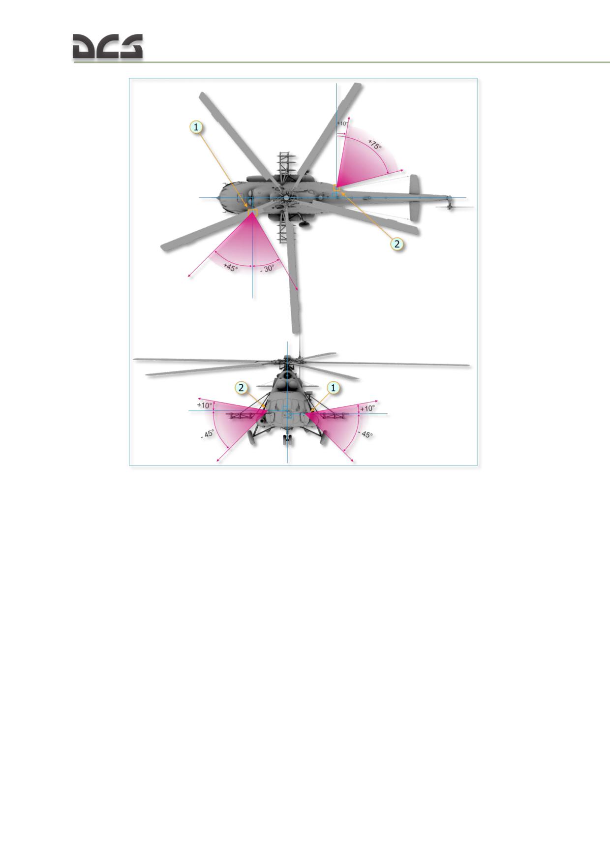
Fig. 11.24. Deflection angles of the KORD and PKT machine guns
in the horizontal and vertical surfaces
1. 12.7-mm KORD machine gun
2. 7.62-mm PKT machine gun
The machine guns are controlled by the AI-gunners, the player can set the ROE
behavior for them. Besides that, the 12.7-mm KORD machine gun can be controlled
by the player, see here.
Implementation of the 12.7-mm KORD machine gun in the game
In the game, this machine gun is installed on the floor in the helicopter’s cargo cabin,
Fig. 11.25:
336
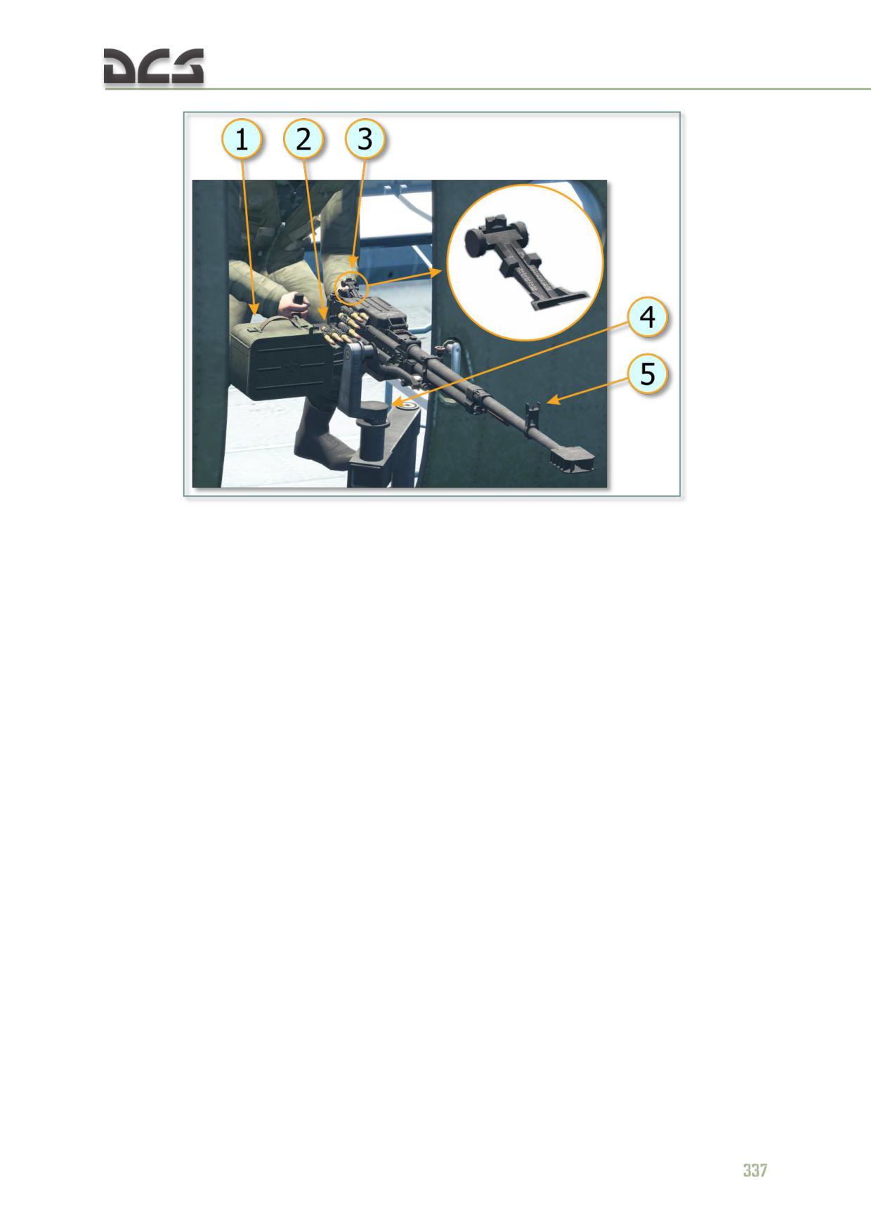
Fig. 11.25. Implemetation of the 12.7-mm KORD machine gun in the game,
main elements
1. Ammo box 12.7-мм (50 rounds)
4. Mounting rack
2. Ammo belt with cartridges
5. Front sight post
3. Tangent rear sight with calibrated markings for
ranges
Reload of a new ammo belt takes around 5-7 seconds.
Machine guns deployment, see here.
11.9.5. Bomb delivery system
Purpose
The bomb delivery system is designed to be employed against ground targets using
aimed bombing with 100, 250, or 500 kg free-fall bombs released from level flight
within visual target contact in day and night time conditions.
Components
The bomb delivery system includes the following components:
six weapons stations equipped with БДЗ-55ТН (BDZ-55TN) suspension
locks
ОПБ-1Р (OPB-1R) optical bombing sight with “ЛЕВО - ПРАВО” (LEFT-
RIGHT) cueing signal lighting
ЭСБР-3П/А (ESBR-3P/A) electrical release control system
system controls
Description
At altitudes between 100 - 4000 m, bomb sighting is performed by the copilot using
the OPB-1R optical bombing sight. At altitudes below 100 m, bomb sighting is
performed by the pilot using the PKV collimating sight.
The right KSB-49 remote bomb release trigger and the BOMB RELEASE switch of the
OPB-1R optical bombing sight are used by the copilot for tactical (combat) release of
bombs. The release switches are connected to the release circuits via the BOMBS
MASTER switch.
The left KSB-49 remote bomb release trigger is used by the pilot for tactical (combat)
release of bombs. The switch is connected to the release circuits via the BOMBS
MASTER switch.
The bomb delivery system provides both the pilot and copilot the ability to release
bombs tactically or jettison in case of emergency. Tactical release is always
performed for bomb detonation and in a particular release sequence based on the
position of the PAYLOAD PROFILE selector on the bombs control panel and the signal
setting switch of the ESBR electrical release control box.
Bombs jettison can be performed either for detonation or not depending on the
position of the ARM switches on the corresponding weapon control panels.
When jettisoned by the pilot, all bombs, rocket launchers and containers are released
from the weapons stations. When jettisoned by the copilot, all bombs are released
only when the PAYLAOD PROFILE selector is set to position II or V.
When the PAYLOAD PROFILE selector is set to position III or IV, rocket launchers
cannot be released from the weapons stations by the copilot via the bombs control
panel. Rocket launchers can be released by the pilot using the EMER JETTISON
switch on the pilot’s upper weapons control panel. If release by the copilot is
required, the PAYLOAD PROFILE selector must be set to position II or V (to “fool” the
weapons control system that all weapons stations are loaded with bombs).
Free-falling bombs
The DCS Mi-8MTV2 is armed with 100 kg bombs (FAB-100, SAB-100), 250 kg bombs
(FAB-250) (Fig. 11.26), and 500 kg bombs (FAB-500M62). Incendiary bombs are not
implemented.
Fig. 11.26. FAB-250 250 kg free-fall bomb
FAB - high explosive warhead. Designed to be employed against personnel, vehicles
and other types of ground targets.
338
SAB - illumination bombs. Designed to illuminate the battle area in low light
conditions. Can and have previously (Tajikistan) been used as a preventative1
countermeasure against MANPAD and other infrared-guided SHORAD systems.
In DCS, bombs are modeled with impact fuses, making their delivery at low altitudes
dangerous. Delayed fuse modeling is planned.
Bomb employment procedures are described in the To deploy bomb armament
chapter.
1 When operating in canyons/valleys, a covering flight releases 4 - 6 SAB illumination bombs before the primary
flight entered below, forcing any potential air defense assets on the ground to aim in the direction of the
illumination flares as they attempted to target the primary flight helicopters.
WEAPONS
12
EMPLOYMENT
DIGITAL COMBAT SIMULATOR Mi-8МТV2
12.
WEAPONS EMPLOYMENT
12.1. Preparing the module for combat deployment
12.1.1. Selecting helicopter’s payload in the mission editor
If player creates a mission with combat deployment on his own, then, after
placing the helicopter on the map in the mission editor, it is necessary to select
required payload. This is done using the “PAYLOAD” tab in the mission editor
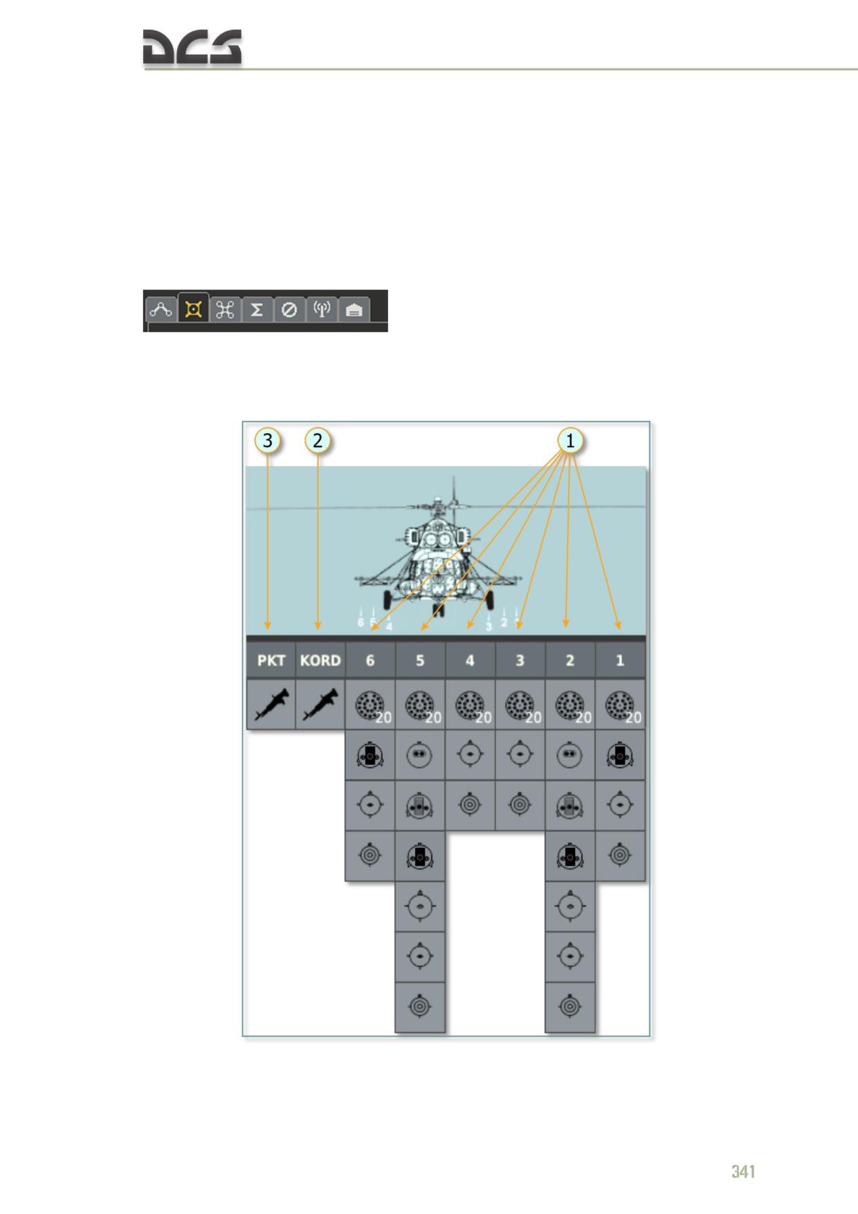
Weapon that can be installed on the hardpoints 1-6, PKT and KORD machine
guns, which can be installed in the cargo cabin, are schematically shown on the
Fig. 12.1
Fig. 12.1. Payload available for the MI-8MTV2 in the mission editor
1. Possible weapon that can be installed on
2. Installs the 12.7-mm KORD machine gun in
the hardpoints from 1 to 6.
the cargo cabin doorway
3. Installs the 7.62-mm PKT in the hatch of
the right cargo bay door
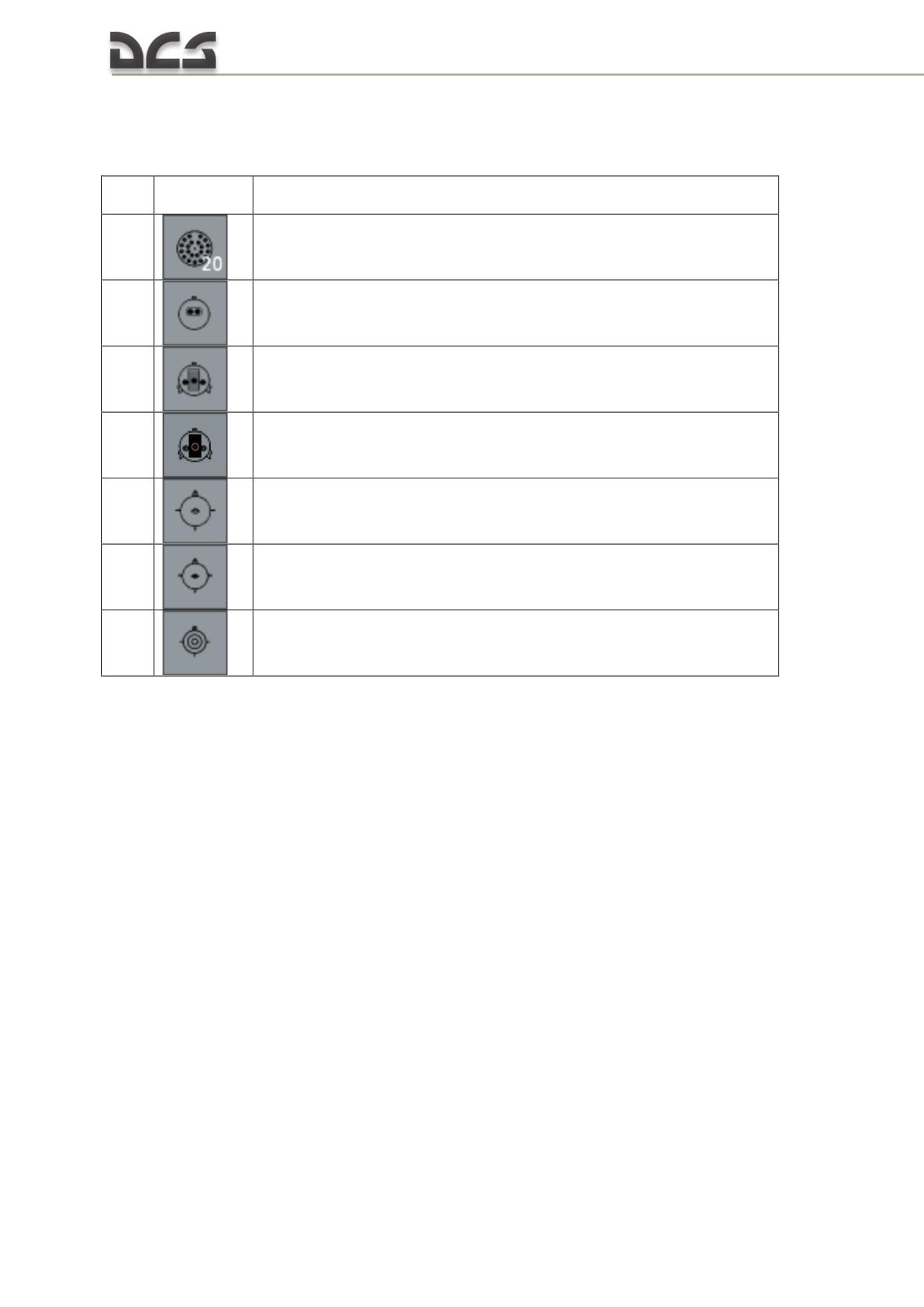
The following weapon is schematically shown (Table 12.1):
Table 12.1
№
Icon in the
Description
ME
1
B8V20 rocket laucnher
2
the UPK-23 gun container with a double-barrel 23-mm gun
3
GUV-1 universal machine gun and grenade launcher container with one
12.7-mm and two 7.62-mm machine guns
4
GUV-1 universal machine gun and grenade launcher container with one
30-mm grenade launcher
5
500-kg bomb
6
250-kg bomb
7
100-kg bomb
More information about mission development can be found in the
12.1.2. Snapviews creation for simplifying interaction with cockpit
objects while playing mission
Described in the chapter 14.4.2.
12.2. The peculiarity of piloting with external payloads
After installation of weapon on external hardpoits, helicopter’s mass center
moves a bit forward. It changes cyclic deflections and pitch angle at all flight
modes. During level flight, balancing position of the cyclic is about 1/5..1/6 of
the full travel range less than in flights without payload on external hardpoints.
During rockets launching (bursts with 8-16 rockets per launcher), ejects form
rocket’s engines impact on the launcher, which accompanied by a small change
in pitch moment (dive moment).
12.3. Weapon’s subsystem enabling procedures
In the 12.3 chapter, procedures for each weapon type, starting from enabling
circuit breakers and to pressing combat trifgger, are described. Enabling the
equipment during combat deployment is considered in the 12.4.
342
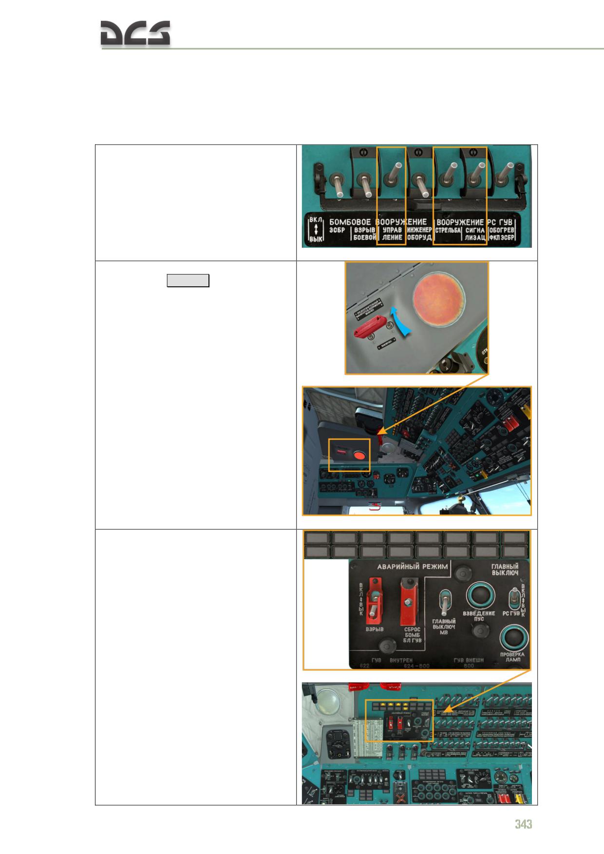
12.3.1. To deploy rockets from the B8V20 launcher
Once helicopter has been started and there is a voltage in the rectifier buses, is
necessary:
Rockets aiming angles table
1. Enable circuit breakers on the
left circuit breaker console (only those
needed for shooting are shown)
2. Enable MASTER ARM
SWITCHES
[Lalt + S]
;
3. On the pilot’s upper armament
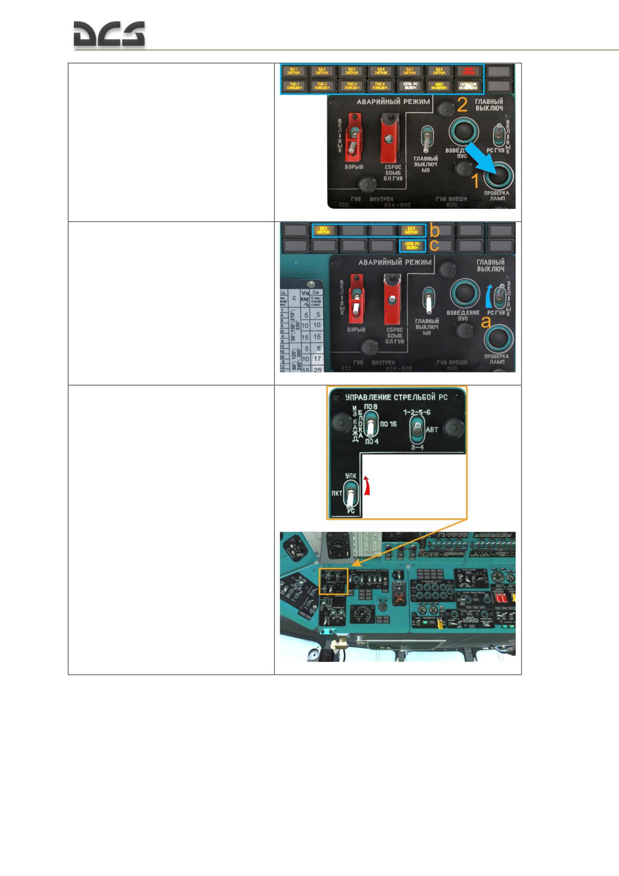
control panel:
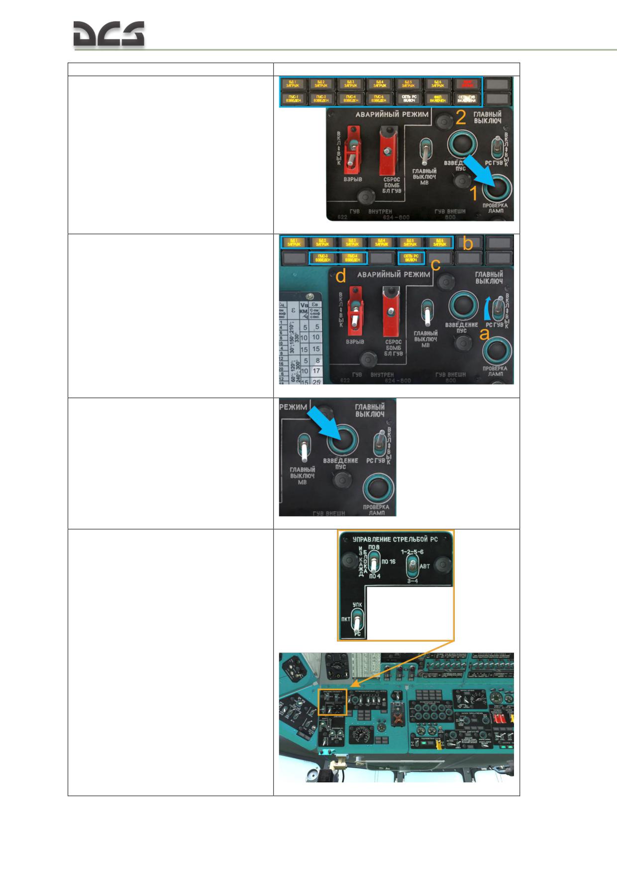
a) by pressing the "ПРОВЕРКА
ЛАМП" (CHECK LAMPS) button
(1) check that all lamps on the
panel are on (2)
b) enable the "ГЛАВНЫЙ
ВЫКЛЮЧАТЕЛЬ РС, ГУВ" (a)
(RKT-GUN MASTER switch) and
check that the "БД
(HARDPOINTS) 3, 4 (1, 2, 5, 6)
ЗАГРУЖЕН (LOADED)" (b),
"СЕТЬ РС ВКЛ." (ROCKETS
LAUNCHING CIRCUIT) (c),
"ПУС (LAUNCHERS) 3, 4 (1, 6)
ВЗВЕДЁН (ARMED)" (d) lights
are on,
depending on payload profile
c) if the "ПУС .. ВЗВЕДЕН" (FCU
LAUNCHER ARMED) light is off,
by pressing "ВЗВЕДЕНИЕ ПУС"
(ARM FCU LAUNCHERS) button,
set the launchers to their initial
position;
4. On the pilot’s lower armament
control panel,
on the УПРАВЛЕНИЕ СТРЕЛЬБОЙ РС
(ROCKETS LAUNCHING CONTROL) panel:
344
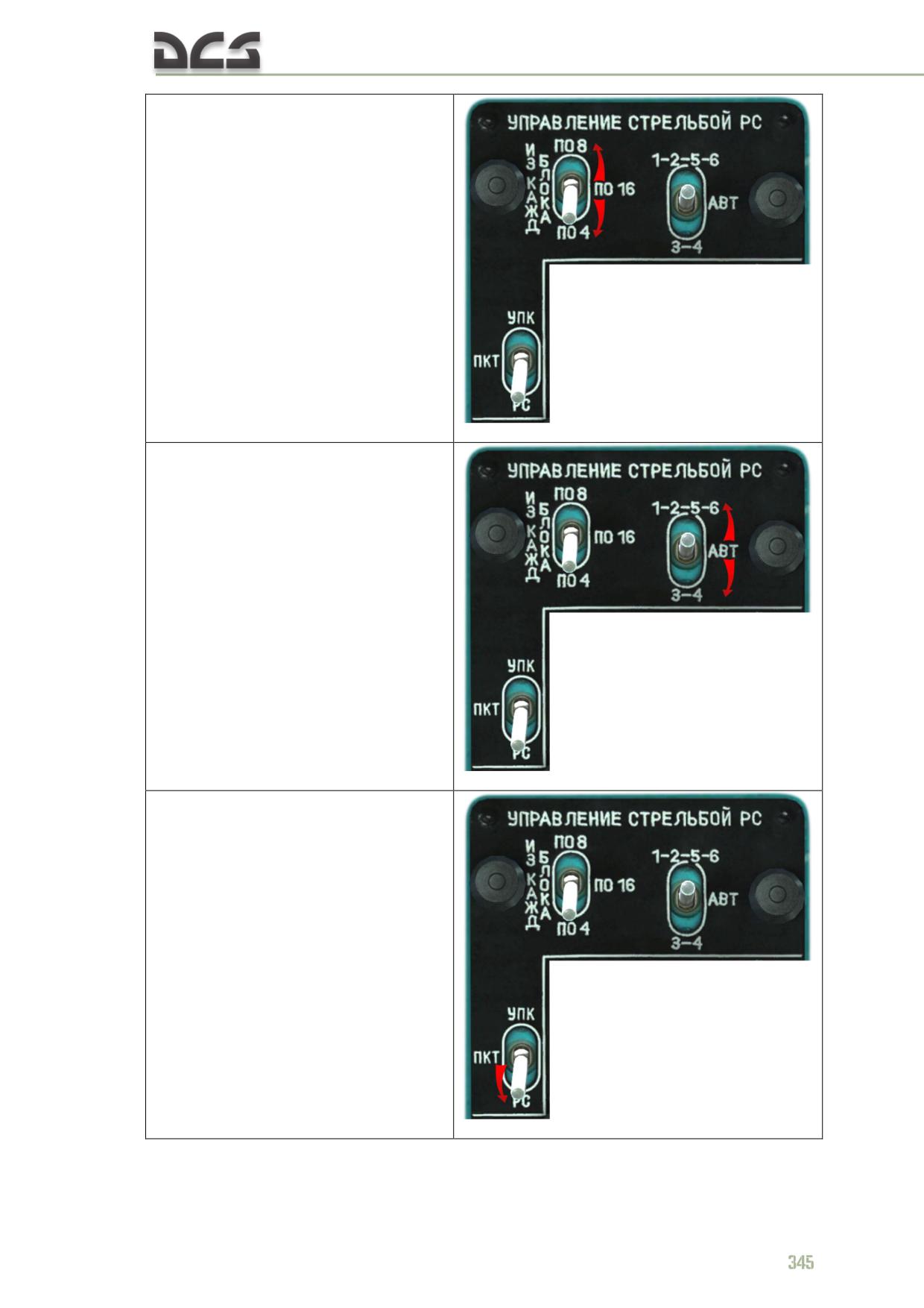
a) by using the "ИЗ КАЖДОГО
БЛОКА - по 8 - по 16 - по 4"
(FROM EACH POD burst of 8 -16
-4 rockets) rockets quantity
selector switch, set the required
number of rockets to be fired
from each launcher ("по 8" -
each long press of the combat
trigger will fire 8 rockets from
each launcher, "по 16" and "по
4" - 16 and 4 rockets
correspondingly). By default, this
switch is set to the "по 4"
(down) position
b) by the "1-2-5-6 - АВТ (AUTO)
- 3-4" switch connect the
required launchers: in the АВТ
(AUTO) position - rockets will be
fired from launchers on
hardpoints 1, 2, 5 and 6 (if they
are mounted there), and when
they are empty, system will
automatically switch to firing
from launchers on hardpoints 3
and 4. In any other position, only
launchers on corresponding
hardpoints will be fired. By
default, this switch is set to АВТ
(AUTO) (middle position)
c) by the "УПК-ПКТ-РС" (UPK-
PKT-ROCKETS) switch, connect
rockets launching circuits to the
combat button by setting it to the
"РС" (ROCKETS) (down) position;
by default this switch is set to the
"РС" (ROCKETS) position
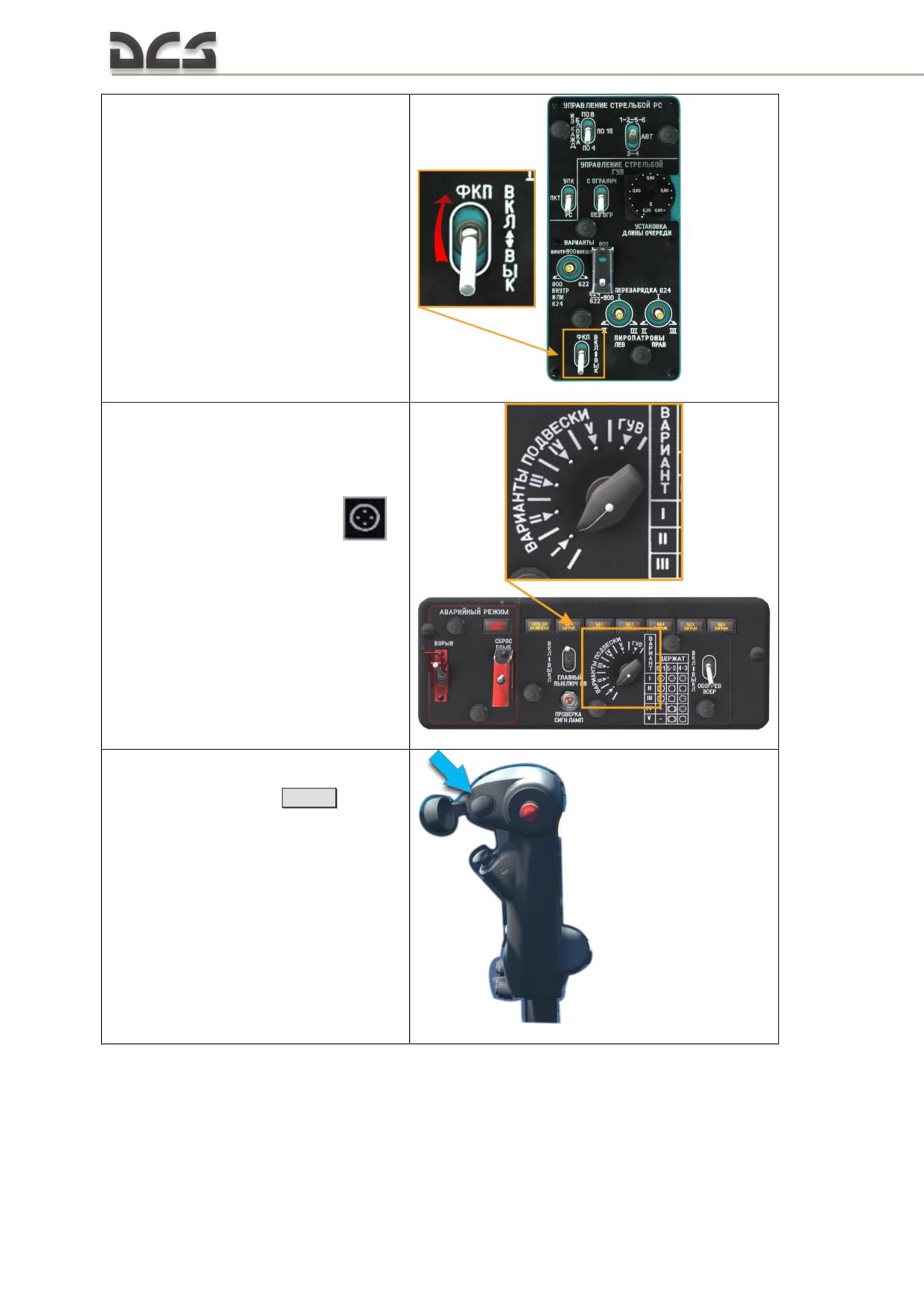
5*. Enable the gun camera (optionally).
To watch photos, taken by the gun
camera, player must enable gun camera
functionality in the special tab of the
module settings
6*. On the co-pilot’s bomb armament
panel set the "ВАРИАНТЫ ПОДВЕСКИ"
(PAYLOAD PROFILE) selector to the
position, corresponding to current
payload: shooting is possible from only
those hardpoints, which have the
symbol in the payload profile (for B8V20 it
is I (all laucnhers), III (launchers on 3rd
and 4th hardpoints), IV (launchers on 3rd
and 4th hardpoints))
7. Press the РС (ROCKETS) button
on the cyclics under the safety cover
- rockets will be fired
[Space]
12.3.2. To deploy UPK-23-250 23-mm gun container
Once helicopter has been started and there is a voltage in the rectifier buses, is
necessary:
346
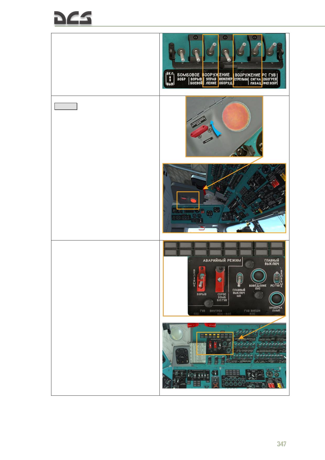
1. Enable circuit breakers on the left
circuit breaker console (only those needed
for shooting are shown)
2. Enable MASTER ARM SWITCHES
[Lalt + S]
;
3. On the pilot’s upper armament
control panel:
a)* by pressing the "ПРОВЕРКА
ЛАМП" (CHECK LAMPS) button
(1) check that all lamps on the
panel are on (2)
b) enable the "ГЛАВНЫЙ
ВЫКЛЮЧАТЕЛЬ РС, ГУВ" (a)
(ROCKETS GUV MASTER
SWITCH) and check that the "БД
(HARDPOINTS) 2, 5 ЗАГРУЖЕН
(LOADED)" (b),
"СЕТЬ РС ВКЛ." (ROCKETS
LAUNCHING CIRCUIT) (c),
lights are on
4. On the pilot’s lower armament
control panel, on the УПРАВЛЕНИЕ
СТРЕЛЬБОЙ РС (ROCKETS LAUNCHING
CONTROL) panel, by the "УПК-ПКТ-РС"
(UPK-PKT-ROCKETS) switch, connect
UPK-23-250 firing circuits to the combat
button by setting it to the "УПК" (UPK)
(up) position
348
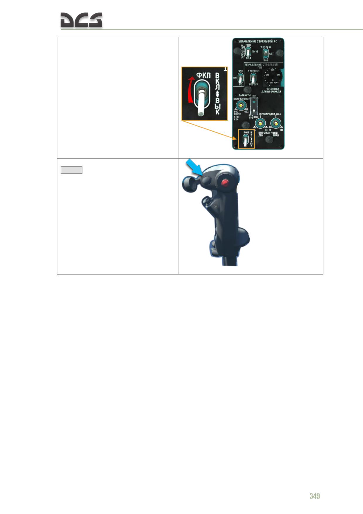
5*. Enable the gun camera
(optionally). To watch photos, taken by
the gun camera, player must enable the
gun camera functionality in the special tab
of the module settings.
6. Press the РС (ROCKETS) button
[Space]
on the cyclics, under the
safety cover (can be opened using
mouse) - bursts of 8-10 rounds from
each gun will be fired.
12.3.3. To deploy the 12.7-mm (7.62-mm) machine guns and 30-mm
grenade launchers from GUV-1
Once helicopter has been started and there is a voltage in the rectifier buses, is
necessary:
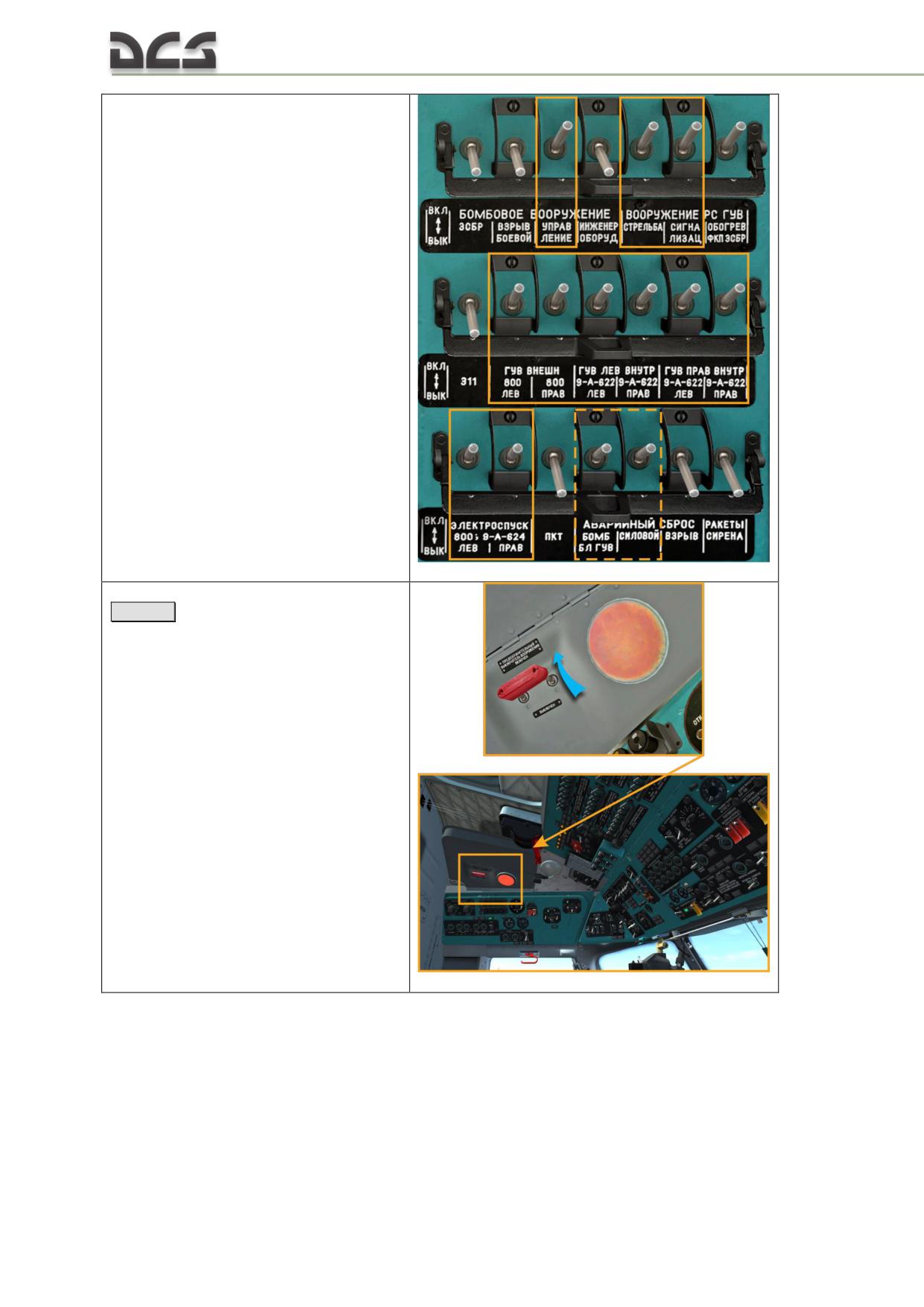
1. Enable circuit breakers on the left
circuit breaker console (only those needed
for shooting are shown with solid line,
those needed for emergency jettison are
shown with dashed line, see 12.5.2)
2. Enable MASTER ARM SWITCHES
[Lalt + S]
;
350
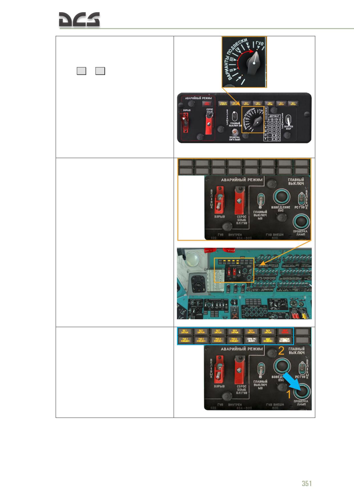
3. On the co-pilot’s bomb
armament panel set the
"ВАРИАНТЫ ПОДВЕСКИ" (PAYLOAD
PROFILE) to the "ГУВ" GUV position,
using
[ . ]
or
[ ; ]
In this position firing and signalization
circuits of the GUV containers are
connected (see 4 b), while rockets’, UPK’s
and bombs’ circuits are disconnected.
4. On the pilot’s upper armament
control panel:
a)* by pressing the "ПРОВЕРКА
ЛАМП" (CHECK LAMPS) button
(1) check that all lamps on the
panel are on (2)
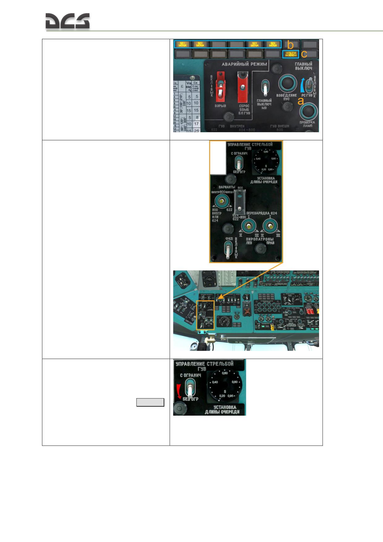
b) enable the "ГЛАВНЫЙ
ВЫКЛЮЧАТЕЛЬ РС, ГУВ" (a)
(ROCKETS GUV MASTER
SWITCH) and check that the "БД
(HARDPOINTS) 1, 2, 5, 6
ЗАГРУЖЕН (LOADED)" (b)
(depending on payload),
"СЕТЬ ГУВ ВКЛ." (GUV FIRING
CIRCUIT) (c)
lights are on
4. On the pilot’s lower armament
control panel, on the
УПРАВЛЕНИЕ СТРЕЛЬБОЙ ГУВ
(GUV FIRING CONTROL) panel:
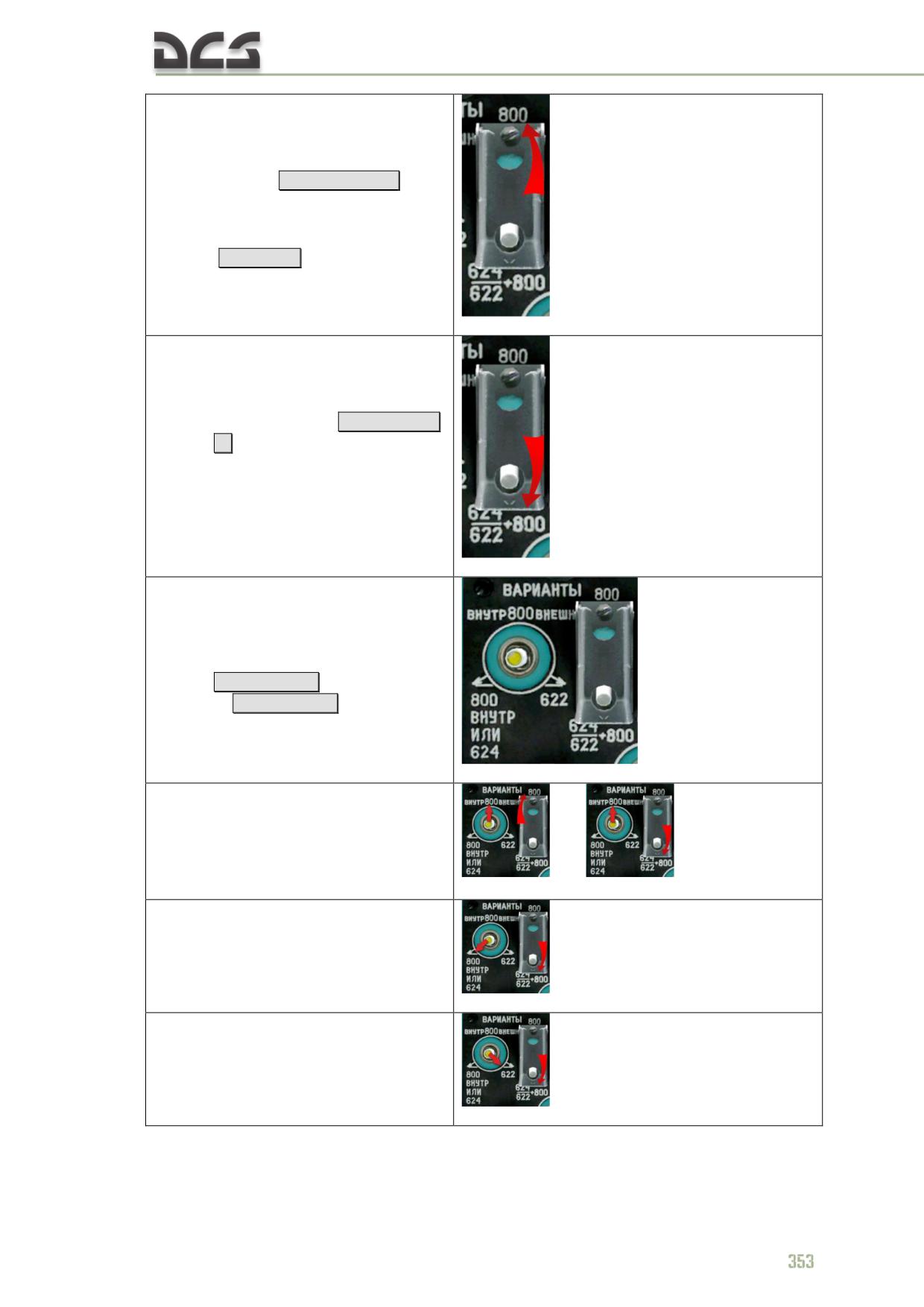
a) set the "УСТАНОВКА ДЛИНЫ
ОЧЕРЕДИ С ОГРАНИЧ - БЕЗ
ОГР" (BURST LENGTH
LIMITATION - NO LIMITATIONS)
to the "БЕЗ ОГР" (NO
LIMITATIONS) (down)
[Lalt + R]
,
in this case burst length will
depend only on how long the
combat button is being kept
pressed
352
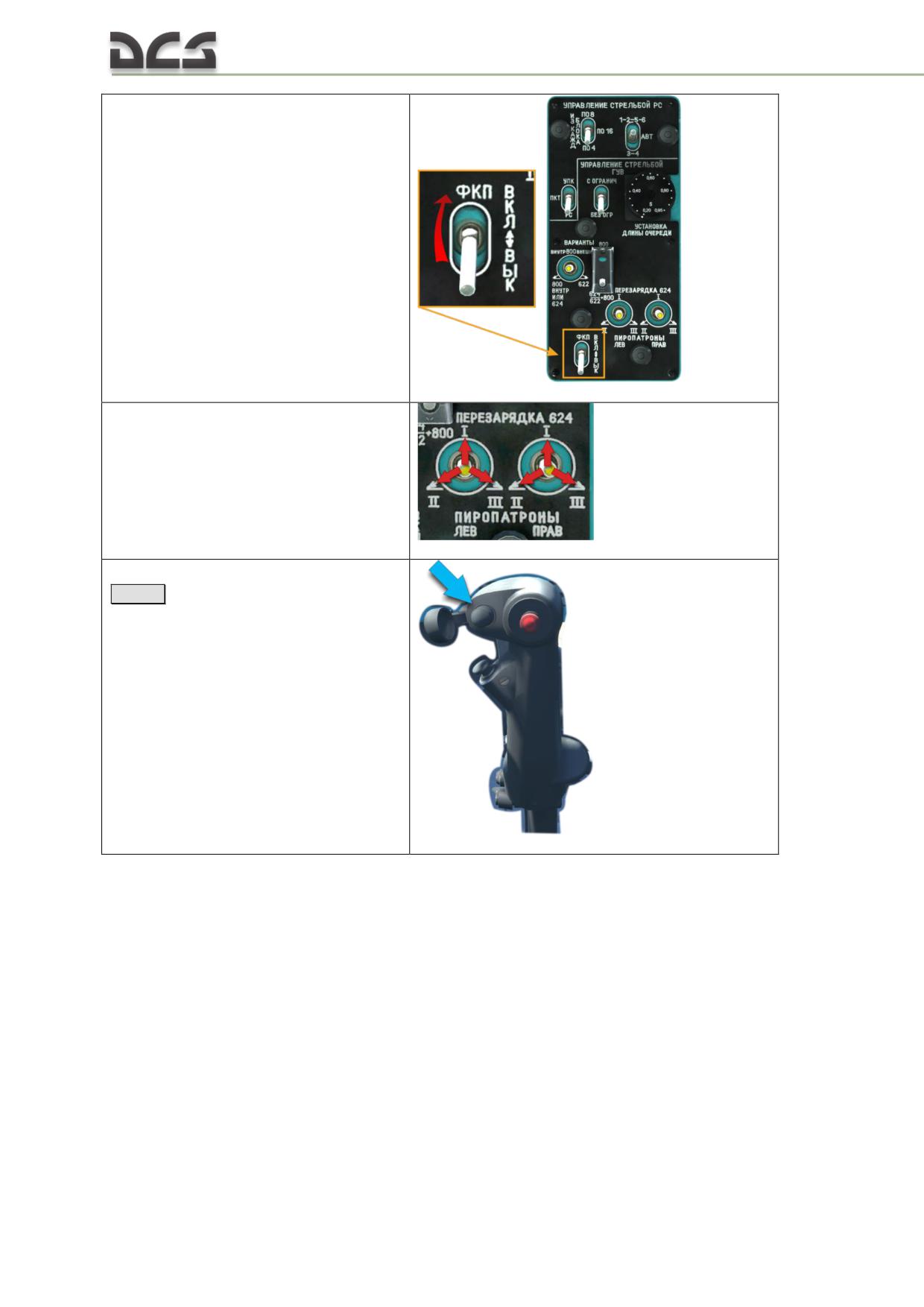
b) set the "ВАРИАНТЫ
(VARIANTS):
800 - 624/622+800"
switch to the “800” (up)
position
[Ralt + RCtrl + P]
, if
there are GUV grenade launchers
(AP-30) on hardpoints 1,2,5,6;
open the safety cover
[Rshift + O]
c) set the "ВАРИАНТЫ
(VARIANTS):
800 - 624/622+800"
switch to the "624/622+800"
(down) position
[Ralt + RCtrl +
O]
, if there are GUV grenade
launchers (AP-30) on hardpoints
1,6 (or nothing) and machine
gun GUVs with 12.7-mm and
7.63-mm machine guns on
hardpoints 2,5 ; "624/622+800"
is a default position
d) set the 4-position switch
ВАРИАНТЫ ВНУТР 800
ВНЕШ - 800 ВНУТР ИЛИ
624 - 622" (GUV fire
selector switch)
Ralt + RCtrl + [
or
Ralt + RCtrl + ]
into:
- "ВНУТР 800 ВНЕШ" (INTERNAL 800
EXTERNAL) to fire AP-30 on hardpoints
1,6,2,5 simultaneously or 1,6 (if there are
no AP-30 on hardpoints 2 and 5)
или
- "800 ВНУТР ИЛИ 624" (800 INTERNAL
or 624)- to fire 12.7-mm machine guns
on hardpoints 2 and 5;
- "622" - to fire 7.62-mm machine guns
on hardpoints 2 and 5;
6*. Enable the gun camera (optionally).
To watch photos, taken by the gun
camera, player must enable the gun
camera functionality in the special tab of
the module settings
7*. Reload 12.7-mm guns in case of
misfires (misfires are not modelled in the
game)
8. Press the РС (ROCKETS) button
[Space]
on the cyclics, under the
safety cover, to fire the GUVs.
12.3.4. To deploy machine guns in cargo cabin
No need to enable anything from the cockpit.
12.3.5. To deploy bomb armament
Once helicopter has been started and there is a voltage in the rectifier buses, is
necessary:
354
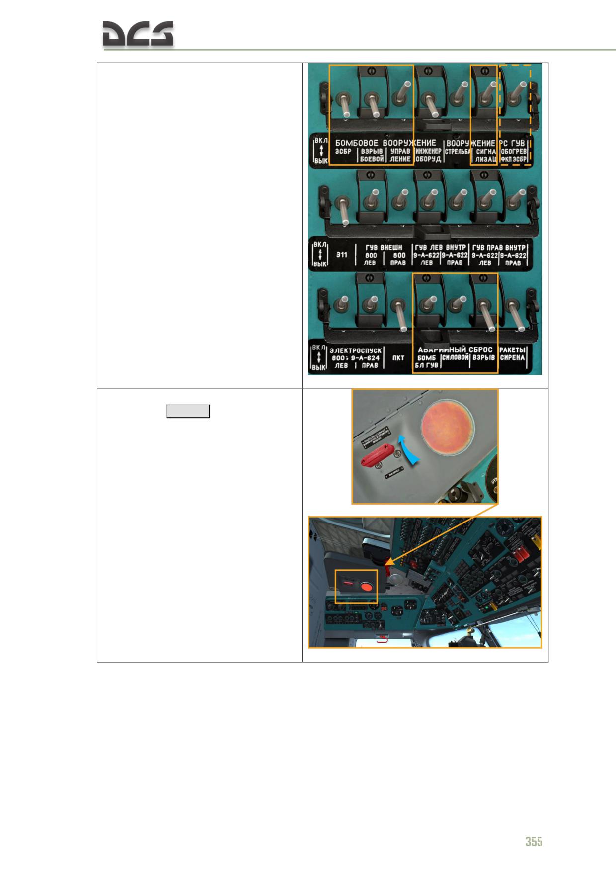
1. Enable circuit breakers on the
left circuit breaker console (only those
needed for bombing and for emergency
jettison, see 12.5.2)
2. Enable MASTER ARM
SWITCHES
[Lalt + S]
;
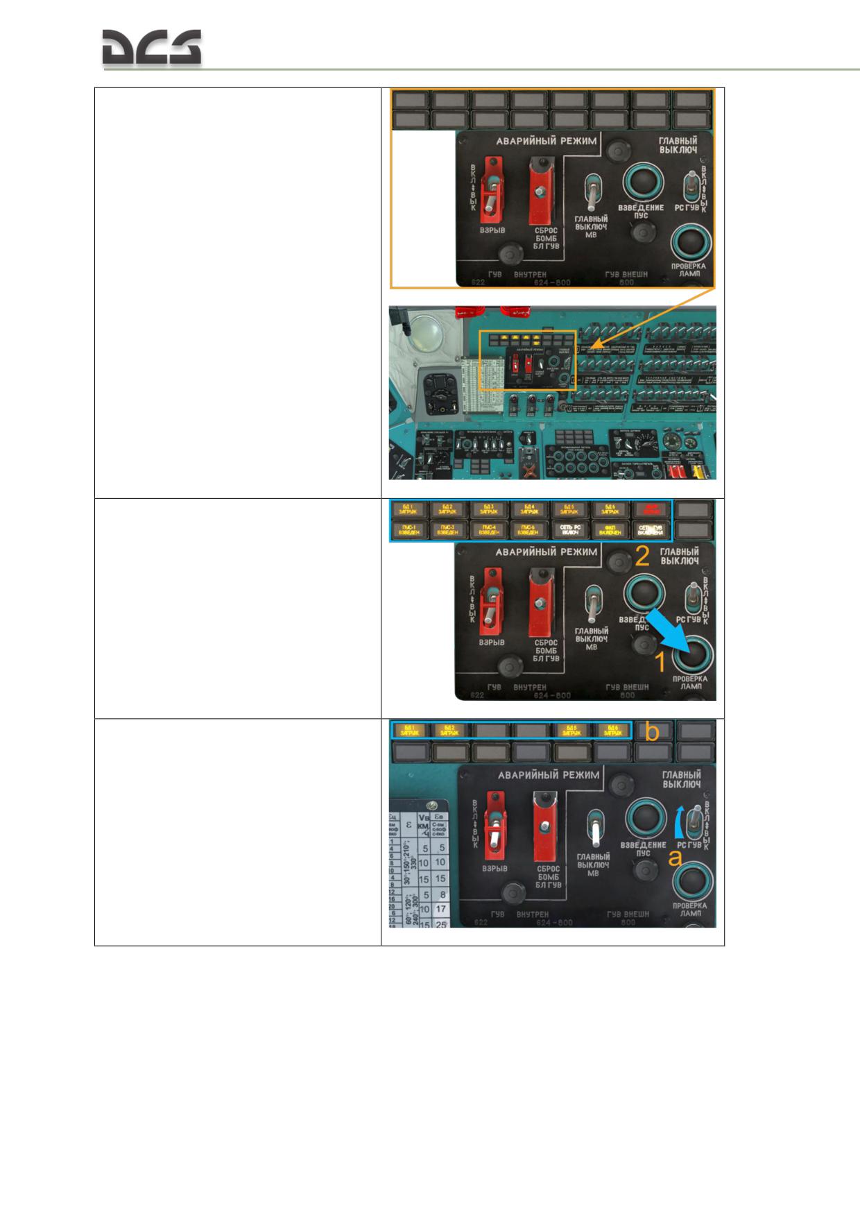
3. On the pilot’s upper armament
control panel:
a)* by pressing the "ПРОВЕРКА
ЛАМП" (CHECK LAMPS) button
(1) check that all lamps on the
panel are on (2)
b) enable the "ГЛАВНЫЙ
ВЫКЛЮЧАТЕЛЬ РС, ГУВ" (a)
(ROCKETS GUV MASTER
SWITCH) and check that the "БД
(HARDPOINTS) 1- 6 ЗАГРУЖЕН
(LOADED)" (b) (depending on
payload) lights are on
356
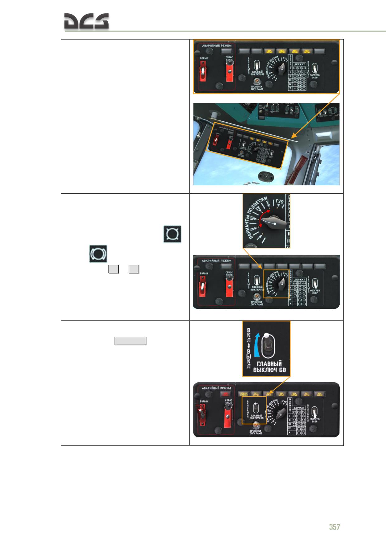
4. On the co-pilot’s weapon
control panel:
a) set the "ВАРИАНТЫ
ПОДВЕСКИ" (PAYLOAD PROFILE)
to the position, corresponding to
the current payload profile with
bombs (those, where the
,
symbols are present)
using
[ . ]
or
[ ; ]
,
which, depending on profile,
connects to tactical and
emergency release circuits only
those hardpoints, on which
bombs are present
b) enable the ГЛАВНЫЙ
ВЫКЛЮЧ. БВ (MASTER ARM
BOMBS)
[RCtrl + P]
after that
corresponding light panels (from
two to six БД1 ЗАГРУЖ - БД6
ЗАГРУЖ. (HARDPOINT 1
LOADED - HARDPOINT 6
LOADED) yellow panels ) go on,
indicating that bombs are present
on hardpoints.
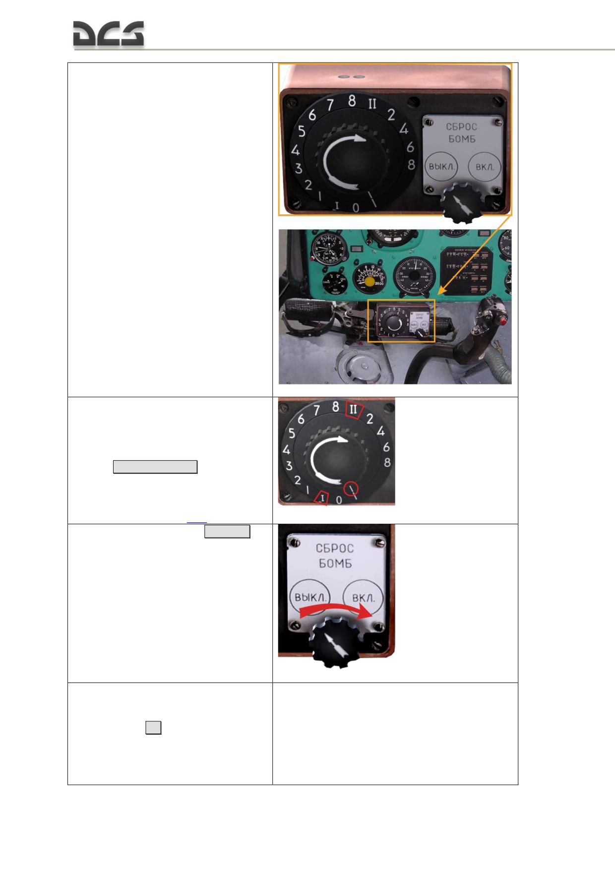
5. On the ESBR-3P/A electrical
release box panel:
a) set the impulse generating
knob to one of the two positions:
position I - for single bomb
release, II - for pair release from
2 hardpoints simultaneously
[Ralt + Rshift + B]
. This rotating
switch is can be rotated only
clockwise. More details about
electrical release box operation
can be found in 11.5
b) enable the ESBR
[Ralt + B]
(to
the right)
c) release bombs, by pressing the
KSB-49 bomb release button (3D-
model is not present in the
game)
[B]
and check that
corresponding light panels on the
co-pilot’s armament control panel
or pilot’s upper armament control
panel go off.
358
12.4. Enabling the equipment during combat deployment
12.4.1. Before taxi (takeoff)
Before weapons can be employed, all of the relevant systems myst be switched
on (see 12.3). Some systems (components) are switched on prior to takeoff
while others are switched on only in the combat area (to avoid unintended
weapons fire). Normally, all of the relevant systems are switched on prior to
takeoff, apart from the weapon systems main power switches. The Mi-8MTV2
weapon systems has three master switches for different types of weapon:
ГЛАВНЫЙ ВЫКЛЮЧ РС ГУВ (RKT-GUN MASTER switch) - connects
firing circuits for launching rockets, firing UPK-23-250 and GUV-1;
ГЛАВНЫЙ ВЫКЛЮЧ МВ (MINELAYING SYSTEM MASTER switch) -
connects circuits for lauching mines from cartridges (not used in the
game);
ГЛАВНЫЙ ВЫКЛЮЧ. БВ (BOMBS MASTER switch) - connects bomb
release circuit.
Besides that, after checking bomb armament, the bomb’s master arm switch
together with ESBR are normally switch off.
1. Before takeoff, enable armament according to the chapter 12.3. To avoid
unauthorized firing or bomb release, disable the ГЛАВНЫЙ ВЫКЛЮЧ РС ГУВ
(RKT-GUN MASTER switch) switch on the pilot’s upper armament control panel
and the ГЛАВНЫЙ ВЫКЛ БВ (BOMBS MASTER switch) switch on the co-pilot’s
weapon control panel (in addition, disable the ESBR on the electrical release
box).
2. Set the required elevation angle on the PKV collimating sight for the given
attack profile (weapon type, flight profile, target range). Use the mouse or
keyboard
[LCtrl + O]
-
[Lalt + O]
shortcuts to turn the PKV elevation angle
knob to set the required elevation angle. If desired, utilize the PKV snapview as
described above (see 14.4.2.). The required PKV elevation angles for various
weapons and attack profiles are provided below:
for employment of B8V20A rocket launchers from level flight in
Table 12.2, Table 12.3
for employment of B8V20A rocket launchers from a dive in Table
12.4
for wind correction during employment of B8V20A rocket in Table
12.5
for employment of UPK-23-250 in level flight in Table 12.6
for employment GUV-8700 YakB 12.7-mm guns in Table 12.7
for employment GUV-8700 GShG-7.62 mm guns in Table 12.8
for employment GUV-8700 AP-30 automatic grenade launcher in
Table 12.9
for bombing from low altitudes using the PKV collimating sight in
Table 12.10
3. Prior to flight (takeoff), it is recommended to prepare, in particular for the
attack phase, by mentally picturing the sequence of events: target search,
aiming, aim adjustment based on conditions, exiting the attack, checking for
threats or return fire.
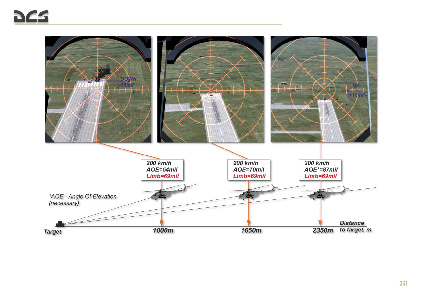
4. As experience with employment of rocket and cannon/gun systems
increases, the interval between subsequent salvos of fire tends to close to 3 - 5
seconds. At an airspeed of 180 - 200 kph the helicopter closes approximately
250 - 285 meters or range to the target, requiring a nose down aim adjustment
of approximately 3 - 6 mils (1/2 reticle subtension). Additionally, any speed
increase also requires an aim adjustment. For example an increase of 20 kph
requires a reduction of elevation by 4 - 5 mils (1/2 reticle subtension).
As such when initiating a rocket or cannon/gun attack run at maximum range,
raise the reticle cross above the target in accordance with the calculated
adjustment. As the target range closes toward minimum range, lower the reticle
cross by approximately 1 subtension (10 mils) for each 5 seconds of flight time
at 200 kph (see Fig. 12.2). If airspeed increases in the attack run to 250 kph,
the reticle adjustment during the attack may be as high as 2 - 3 subtensi
360
DIGITAL COMBAT SIMULATOR Mi-8МТV2
Fig. 12.2. Estimated required target elevation angle in three points of the attack run without adjusting the PKV elevation knob
DIGITAL COMBAT SIMULATOR Mi-8МТV2
12.4.2. The required PKV elevation angles for various weapons and
attack profiles
SIGHT ELEVATION FOR EMPLOYMENT OF B8V20A ROCKET LAUNCHERS FROM LEVEL FLIGHT:
Table 12.2
Sight elevation setting for S-8KOM (and other types with mass of 11 - 12
Target range at
kg) from B8V20A launchers from level flight, in mils, for various airspeeds,
launch, m
in kph
100
100
1000
82
1000
82
1000
1500
90
1500
90
1500
2000
100
2000
100
2000
2500
114
2500
114
2500
3000
128
3000
128
3000
3500
146
3500
146
3500
Table 12.3
Sight elevation setting for S-8OFP2 (mass 16.7 kg) from B8V20A
Target range at
launchers from level flight, in mils, for various airspeeds, in kph
launch, m
100
100
1000
100
1000
100
1000
1500
112
1500
112
1500
2000
125
2000
125
2000
2500
139
2500
139
2500
3000
152
3000
152
3000
3500
169
3500
169
3500
return to unguided rocket system description
return to PKV collimating sight description
SIGHT ELEVATION FOR EMPLOYMENT OF B8V20A ROCKET LAUNCHERS FROM A DIVE:
Table 12.4
Sight elevation setting for
employment of B8V20A
Dive entry
Airspeed at
Target range
launchers of various
Dive angle, deg
airspeed, kph
launch, kph
at launch, m
rocket types from a dive,
mils
S-8КОM
1500
68
2000
74
10
150
180
2500
82
3000
92
3500
104
1500
64
20
150
200
2000
70
2500
78
3000
88
3500
98
4000
110
4500
128
WIND CORRECTION (B8V20A):
Table 12.5
Wind correction, mils
Wind direction on attack course, deg
Wind speed, m/s
S-8КОМ
5
5
30°; 150°; 210° и 330°
10
10
15
15
5
8
60°;120°; 240° и 300°
10
17
15
25
5
10
90° и 270°
10
19
15
29
SIGHT ELEVATION FOR EMPLOYMENT OF UPK-23-250 IN LEVEL FLIGHT:
Table 12.6
Sight elevation settings for employment of GSh-23L cannon (UPK-23-250
Indicated
pod) against ground targets from level flight at various target ranges, in mils
airspeed, kph
500 m
1000 m
1500 m
2000 m
2500 m
3000 m
0
48
56
72
90
-
-
100-250
44
54
66
84
102
123
SIGHT ELEVATION FOR EMPLOYMENT GUV-8700 YAKB 12.7-MM GUNS:
Table 12.7
Dive
Sight elevation settings for employment of
Target range,
angle,
YakB-12.7 (GUV), in mils, for various airspeeds, in kph
m
deg
0
100
150
200
250
500
65
65
65
60
60
1000
70
70
70
65
65
0
1500
80
80
80
75
70
2000
95
95
90
90
85
500
-
-
60
60
55
1000
-
-
65
65
60
10
1500
-
-
75
70
65
2000
-
-
85
85
80
500
-
-
55
50
45
1000
-
-
60
55
50
20
1500
-
-
70
65
60
2000
-
-
80
75
70
500
-
-
45
40
-
30
1000
-
-
50
45
-
1500
-
-
60
55
-
2000
-
-
70
65
-
SIGHT ELEVATION FOR EMPLOYMENT GUV-8700 GSHG-7.62 MM GUNS:
Table 12.8
Sight elevation settings for employment of
Dive angle,
Target range,
GShG-7.62 (GUV), in mils, for various airspeeds, in kph
deg
m
0
100
150
200
250
500
65
60
60
60
55
1000
70
70
70
65
65
0
1500
90
90
85
85
80
2000
120
120
115
110
105
500
-
-
60
55
55
1000
-
-
65
65
60
10
1500
-
-
85
80
65
2000
-
-
110
110
80
500
-
-
50
50
45
1000
-
-
60
55
50
20
1500
-
-
75
75
60
2000
-
-
100
100
70
SIGHT ELEVATION FOR EMPLOYMENT GUV-8700 AP-30 AUTOMATIC GRENADE LAUNCHER:
Table 12.9
Sight elevation settings for employment of
Dive angle,
Target range,
AP-30 (GUV), in mils, for various airspeeds, in kph
deg
m
100
140
160
180
200
220
250
800
80
70
65
60
50
45
30
1000
115
105
100
90
85
75
60
0
1500
225
200
190
175
165
155
135
2000
-
-
-
-
-
245
225
800
-
70
65
60
50
40
30
1000
-
105
100
90
80
70
55
10
1500
-
195
185
175
160
150
130
2000
-
-
-
-
-
237
217
800
-
65
60
50
40
30
-
1000
-
90
85
75
70
60
-
20
1500
-
175
165
155
145
130
-
2000
-
-
-
240
220
215
-
N O T E . Generally multiple bursts are assumed in an attack run, but adjusting the sight
elevation setting between bursts is not practical as there is not sufficient time in the attack.
Given the attack plan (starting target range, ending target range, weapons planned for
employment, etc), a maximum and minimum range is calculated. The sight elevation setting is
set to the average range between the calculated maximum and minimum ranges. When
planning the attack, the difference between the resultant sight elevation setting and the closest
matching setting in the chart is taken as a basis for calculating high or low correction on the
reticle sight during the attack phase. For example see (Fig. 12.2). In the simulation, the default
sight elevation setting is 69 mils, which can be taken as a basis for calculating the required
reticle correction in the attack phase.
364
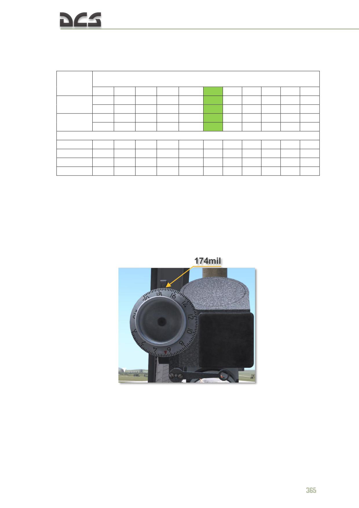
SIGHT ELEVATION FOR BOMBING FROM LOW ALTITUDES USING THE PKV COLLIMATING SIGHT:
Table 12.10
Sight elevation setting, in mils, for various ground speeds, in kph
Altitude, m
Release delay, sec
150
160
170
180
190
200
210
220
230
240
250
200
200
200
200
183
174
165
157
149
140
123
50
1.0
0.5
0.5
-
-
-
-
-
-
-
-
200
200
200
200
200
200
200
200
200
200
200
100
3.0
2.5
2.0
2.0
1.5
1.0
0.5
0.5
0.5
-
-
Release delay, sec
150
6.0
5.5
5.0
4.5
4.0
3.5
3.0
2.5
2.0
1.5
1.0
200
8.5
7.5
7.0
6.5
6.0
5.5
5.0
4.5
4.0
3.5
3.0
250
11.5
10.5
10.0
9.5
8.5
8.0
7,.0
6.0
5.5
5.0
4.5
300
15.0
14.0
13.0
11.5
10.0
9.5
9.0
8.5
7.5
6.5
6.0
N O T E
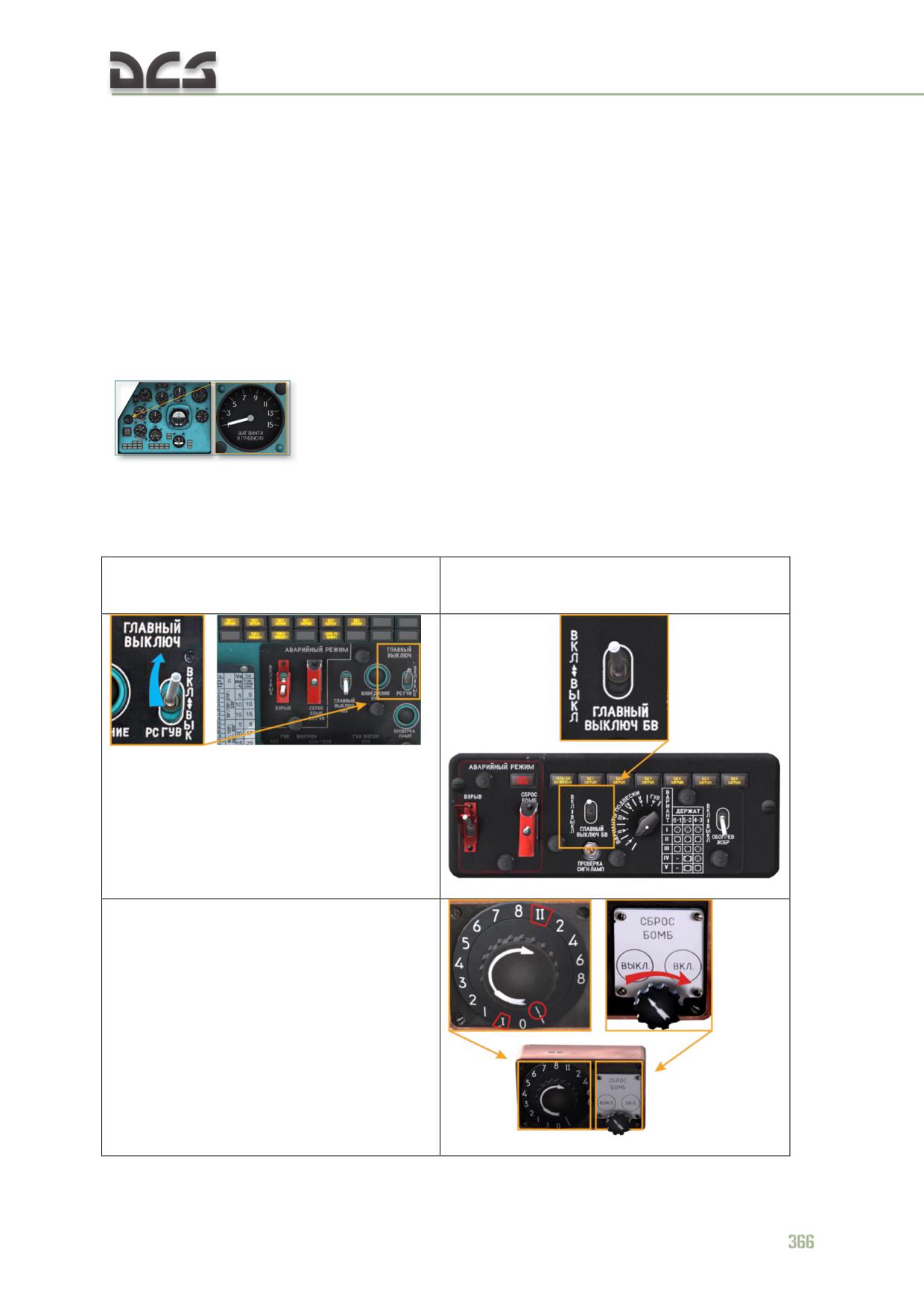
1. The required sight elevation setting must be set by rotating the elevation knob on the PKV
collimating sight. For example, for a release from an altitude of 50 m at 200 kph, the elevation
setting must be set to 174 mils, as demonstrated in (Fig. 12.3).
2. Release delay - the time delay between the target passing throught the bottom point of
the outer reticle ring (along the center vertical line or displaced to either side in case of
crosswind or sideslip) and bomb release.
3. When employing bombs from low altitude, a fuze delay setting is used to avoid damaging the
helicopter and crew (not currently implemented)
Fig. 12.3. Setting 174 mil elevation on the PKV sight
DIGITAL COMBAT SIMULATOR Mi-8МТV2
12.4.3. Attack run
1. The approach to the target area must be planned and flown so as to minimize the
chances of detection by hostile forces and engagement by hostile air defense assets.
Low altitude to nap-of-the-earth (NOE) flight is generally most effective at minimizing
exposure to threats.
When employing rockets or cannon/gun systems, generally the most effective flight
profile in the attack is level flight with an airspeed of 180 - 200 kph in the initial
phase followed by a shallow dive (5 - 10°) in the aiming and firing phase. Once
stabilizing at this airspeed, re-trim the autopilot by neutralizing the deviations on the
autopilot zero indicator, trim the flight controls, take note of the collective pitch angle
(this will be helpful in re-establishing level flight after the
attack).
2. Turn on the RKT-GUN MASTER switch and/or BOMBS MASTER switch and
ESBR as required depending on employed weapon system.
1. The ГВ РС ГУВ (RKT-GUN MASTER switch)
2. The ГВ БВ (BOMBS MASTER switch) and
if rockets, UPK-23-250 or GUV-1 to be
ESBR if bombs to be deployed
deployed
(One must remember, that all other, needed circuit breakers and switches must be
enabled before taxiing and takeoff, see 12.3).
3. At a range of 3000 - 2500 m, perform a pop-up maneuver to gain visual contact
with the target. This can be done either using the cyclic to increase pitch by +10 -
15° or using the collective to increase collective lift. Once attack altitude is reached,
return to level flight by either reducing pitch or collective depending on the method
used to perform the pop-up maneuver.
N O T E . Although the second (collective) option for performing the pop-up maneuver is less
“pretty”, it is nevertheless preferable as it maintains line of sight to the target, avoids increasing own
helicopter’s area of exposure to air defense fire, and prevents a loss of airspeed in the pop-up
maneuver.
4. At the attack altitude, set the collective pitch as required for level flight (angle
noted prior to the pop-up maneuver), search for and identify the target, perform any
required heading corrections to line up with the target, and eliminate any
climb/descent to maintain level flight.
N O T E . Remember that weapons fire in conditions of vertical speed or side sleep becomes highly
inaccurate. Rocket and cannon and machine gun rounds will fall short if fired in a negative vertical
velocity condition and fall long if fired in positive vertical velocity condition. If fired with side slip, the
rounds will tend to fall toward the side of the slip ball. Rockets are particularly sensitive to poor firing
conditions due to their (relatively) low initial velocity of 30 - 50 m/s.
If the attack heading is taken out of a turn, the leveling of the turn should being
when the remaining turn angle approximately equals the turn roll angle, i.e. if the roll
angle in the turn is 40°, begin to level out of the turn onto the attack heading
approximately 40° short of the attack heading. Remember that turns with large roll
angles (exceeding 15°) result in a climbing tendency when the helicopter is leveled
out of the turn, requiring a reduction in collective pitch by 1/8 - 1/6 travel.
Next steps:
Employing rockets or cannon/gun systems:
a) After leveling out of the turn establish level flight at 180 - 200 kph,
eliminate climb/descent rate, center the slip ball (to minimize dispersion)
b) When employing rockets: at 2500 m perform final course corrections to
place the target directly on course, place the sight reticle over the target
with smooth cyclic control, adjust reticle position based on range and wind
correction and initiate weapons fire at 2000 m by pressing the WEAPONS
FIRE switch on the cyclic control handle. When firing the UPK-23-250 or
GUV-1: begin firing at a distance of 1500 -1200 m
c) If multiple salvos are planned, continue to close the range to the target
while making aim corrections for the reduced range and, if required,
increased airspeed (see Fig. 12.2)
d) Turn off the target prior to reaching minimum range (1000 m)
Rocket and cannon/gun fire produces a slight recoil which tends to pitch the
helicopter down due to the payload being positioned below the CG. When firing long
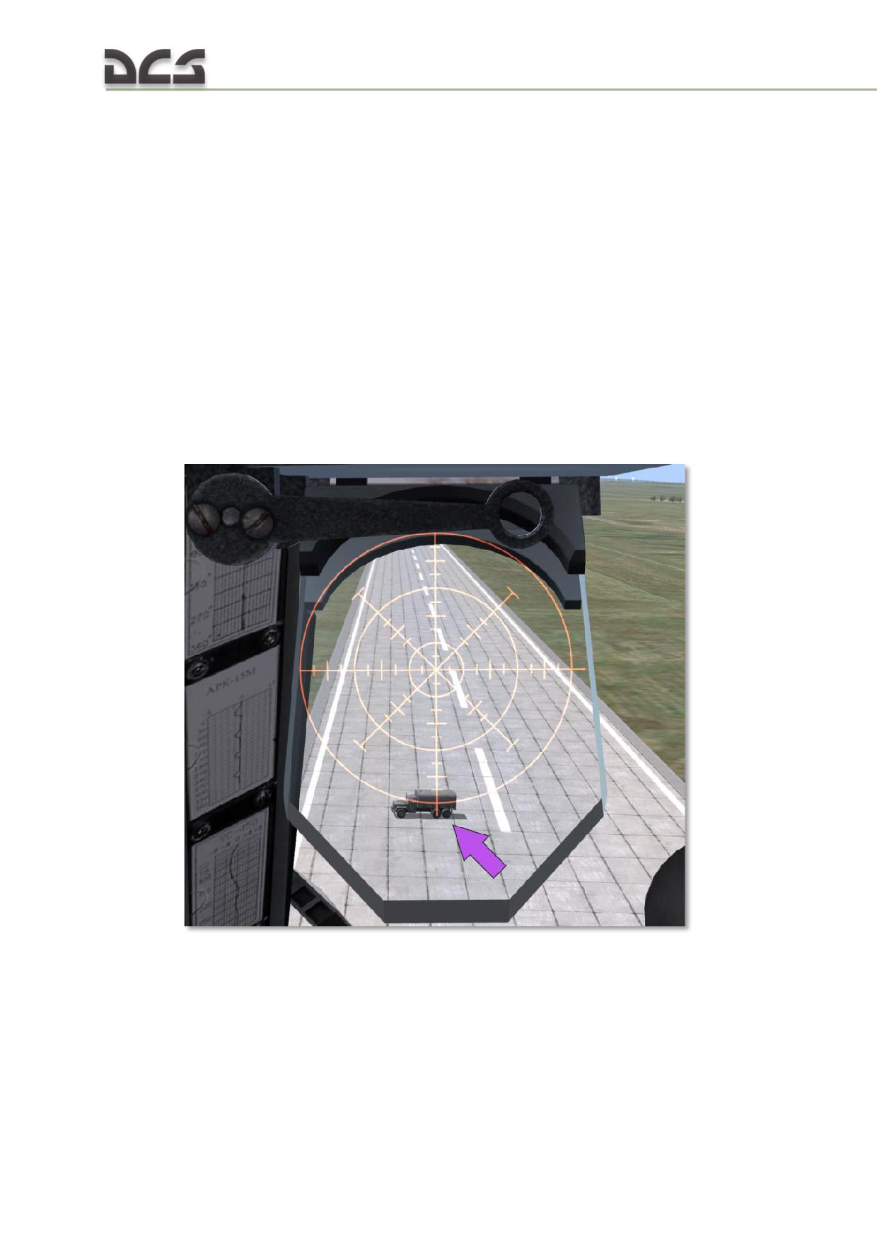
salvos, plan for recoil effects by correcting the reticle position 3 - 5 mils higher to
allow for recoil drop during the fire sequence.
Bomb delivery by the pilot using the PKV collimating sight:
a) Plan the attack run such that it take 10 - 15 sec between initial point and
release points. As experience grows, this time can be reduced.
b) If no crosswind is present, maintain the attack heading such that the
helicopter flight path crossed directly over the target. In this case, the PKV
reticle cross should cross over the target as well.
c) In a crosswind condition, the PKV sight picture has to be adjusted so that
the vertical bar passes to the left (right) of the target at an angle equal to
the slip angle in the opposite direction
d) In a head or tailwind condition (as well as no wind), bombs are released
when the target passes through the bottom of the outside ring of the
reticle (Fig. 12.4);
Fig. 12.4. Bomb release point in calm weather or only head/tailwind; altitude 50 m
e) In a crosswind condition, bombs are released when the target passes
through an imaginary horizontal line that is tangent to the bottom point of
the outside ring of the reticle (Fig. 12.5);
368
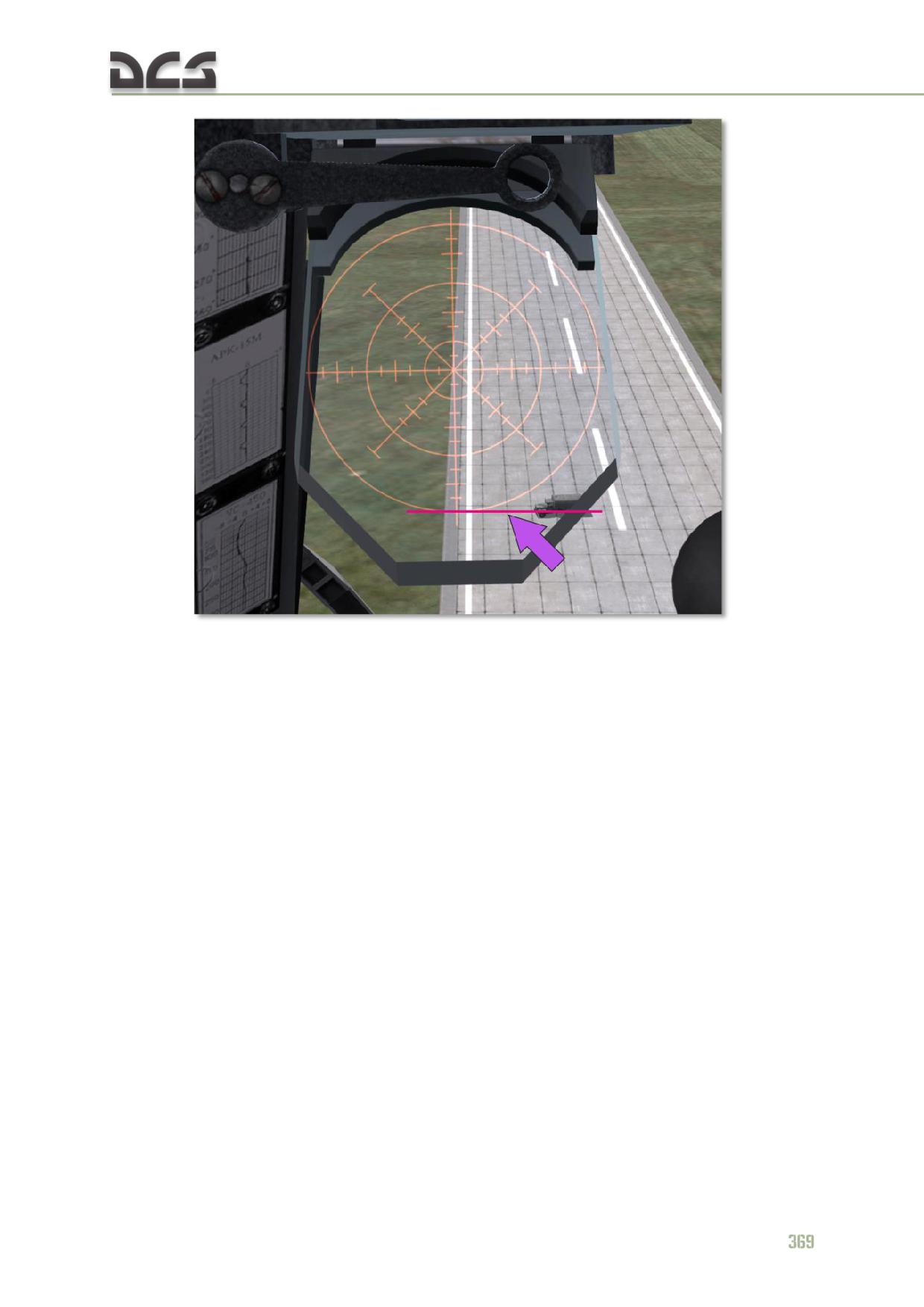
Fig. 12.5. Bomb release point in a LEFT crosswind condition; altitude 100 m
f) If the target line of sight passes under the PKV reticle visible view angles,
the bomb release point is estimated using a countdown. In this case the
PKV elevation is set to the lowest angle of 200 mils.
g) After the target passes through the intersection of the reticle vertical bar
and outside ring, the pilot begins the countdown and releases the bombs
upon completing the countdown..
Bombs released from low altitudes and set for delayed detonation may bounce and
detonate further afield.
12.4.4. Exiting the attack
1. After completing weapons fire, perform an energetic maneuver away from the
target while descending to low altitudes and increasing airspeed to maximum of 230
-
250 kph. To minimize exposure to hostile air defenses, perform evasive
maneuvering: alternating left and right turns of 30 - 40° bank and 40 - 50° heading
(4 - 5 sec) until reaching 1000 - 1500 m of range off the target.
If required, repeat the attack pass(es).
2. When the attack is complete, switch OFF the RKT-GUN MASTER and/or BOMBS
MASTER switches.
3. Navigate to the landing point.
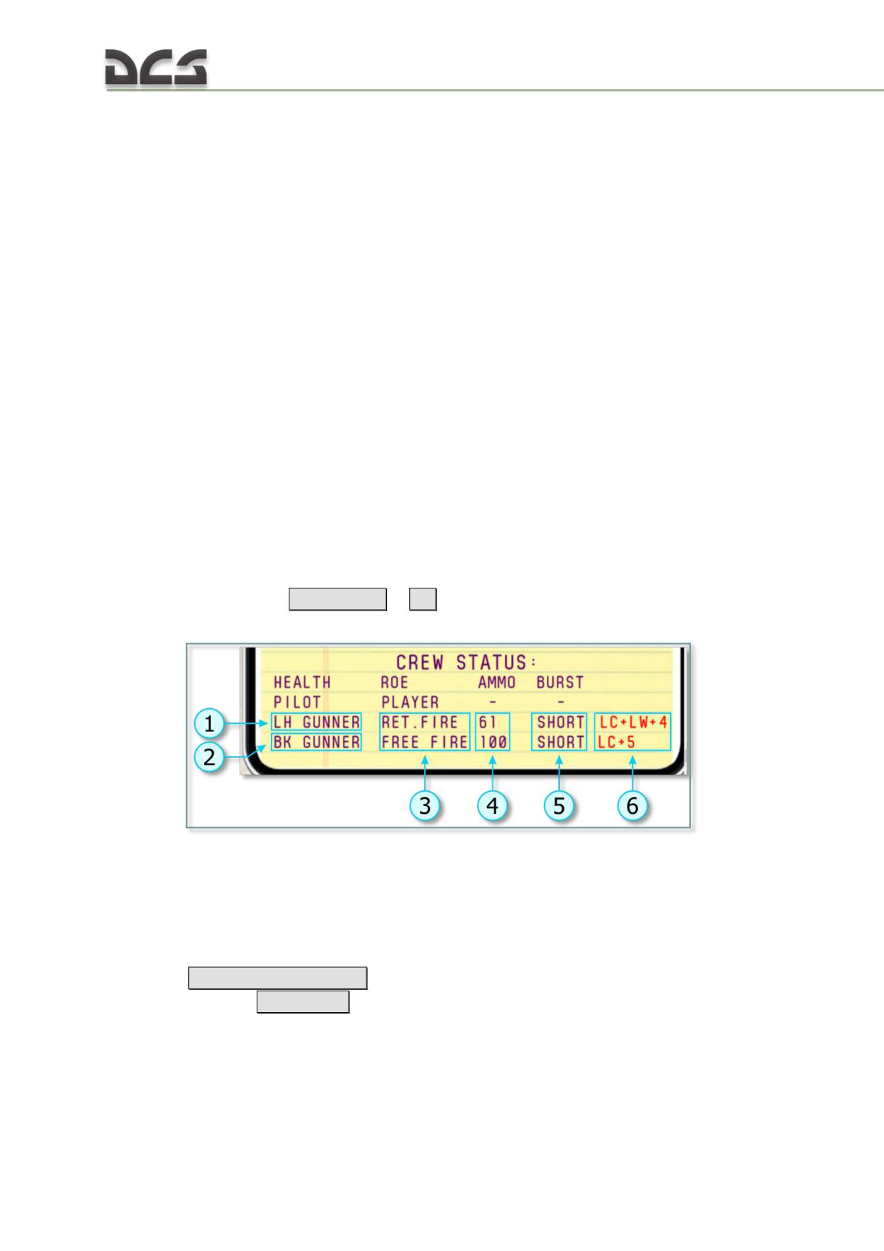
12.4.5. Firing the 12.7-mm KORD and 7.62 PKT machine guns
There are two machine gun stations in the Mi-8. The 12.7-mm machine gun is
installed in the doorway of the cargo bay (further “door gunner”) and 7.62-mm PKT
machine gun in the right cargo bay door (further “tail gunner” or "aft gunner").
These machine guns can be fired by gunners at any time. Gunners are implemented
as AI, but player can control their behavior (ROE) during the game. In addition to
that, player can play as a gunner of the 12.7-mm KORD machinegun.
Control of AI-gunners
Player can control AI-gunners by selecting one of three ROE options:
HOLD - gunners will not fire;
RETURN FIRE (RET. FIRE) - gunners will fire back if the helicopter is
under fire;
FREE FIRE - gunners are free to engage any detected target up to
distance of 800 m. If there are multiple targets, AI-gunner tries to engage
all of them, but most dangerous targets have higher priority.
By default, the HOLD option is selected. Current status is indicated in kneeboard,
ROE column, or in the on-screen hint panel (text on transparent backg2round) while
playing from the gunner place.
To change the behavior of the AI-gunners player must:
1. Activate kneeboard
[Rshift + K]
or
[K]
(to briefly show kneeboard) to see the
current status of the armament and gunners:
Fig. 12.6. AI-gunners status in the kneeboard
1. Door gunner
4. Remaining ammo in percents
2. Tail gunner
5. Burst length (can not be changed here)
3. Current rules of engagement (ROE) status
6. Hotkeys for changing ROE (LC - LCtrl, LW
- Lwin)
2. By the
[LCtrl + Lwin + 4] key command (pressing sequentially) for the door
gunner and by the
[LCtrl + 5]
for the tail gunner, select the desired ROEs and check
them in the kneeboard.
AI-gunners fire short bursts: from 12.7-mm machinegun - 5..7 rounds, from 7.62-
mm machinegun - 7..10 rounds.
370
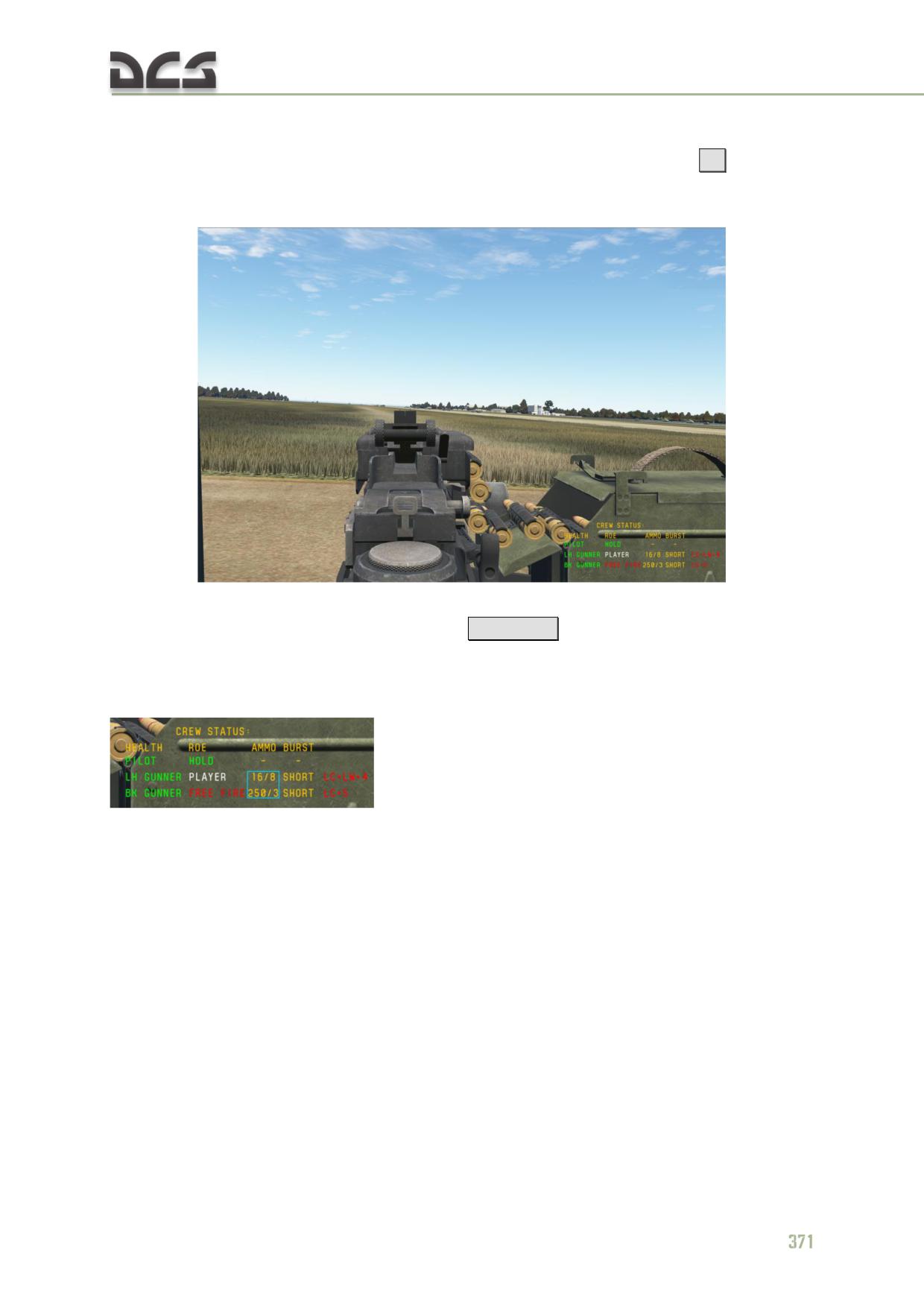
First person playing with the
12.7-mm KORD machinegun
To take a gunner’s place (first person view), player must press the
[4]
key, as a
result, the player takes a seat of the gunner and the gunners’ status transparent
panel appears in the bottom-right corner:
Fig. 12.7. First person view from the door gunner’s seat
Activate/remove the gunner status panel -
[Lwin + H]
This status panel contiains the same information as the kneeboard, except that
remaining ammo is shown not in the percentage from the total ammo, but in rounds
and which ammunition belt is used, starting from the belt №12 and to the belt №1
. In the example here, 16/8 means that there are 16
rounds in the ammunition belt №8 (from 12 available) for the 12.7-mm KORD
machine gun. Similarly for the 7.62-mm PKT machine gun.
First person view and machine gun are controlled by the mouse:
mouse movement left-right moves machine gun to the left-right
correspondingly;
mouse wheel rotation zooms in/out the iron sight.
For aiming, by using the mouse wheel, zoom-in the iron sight of the machine gun:
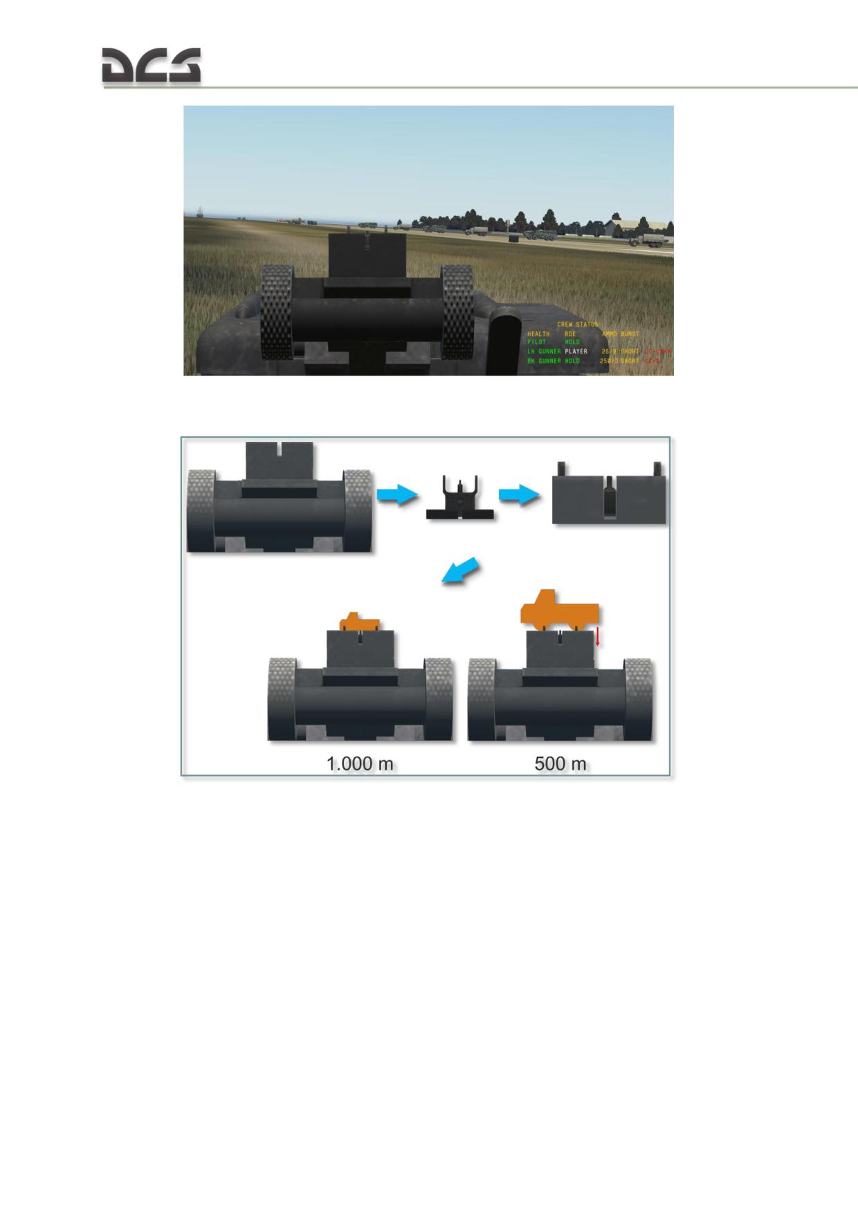
and aling the front sight post or “bead” with the aperture or “crook” and target, Fig.
12.8:
Fig. 12.8. Aiming the machine gun
Iron sights of the machine guns are set to 1,000 m, and if shooting at a target at
approximately this distance, one must aim under the lower edge of the target. If
shooting is performed at smaller distances, one must lower the “bead-crook” line
below target.
Firing guns is performed with help of the left mouse button.
Use of head tracking devices (of TrackIR type) while playing as
a gunner
In case, if in addition to existing input devices (keyboard, mouse, joysticks) there is a
head tracking device (TrackIR), views and gun can be controlled in three different
ways:
372
TrackIR controls view, mouse - gun (default behavior, when taking
gunner seat);
TrackIR controls both view and gun;
TrackIR is disabled by the hot-key from TrackIR program
[F9]
, and then
mouse controls view and gun.
Modes can be change sequentially by the command
[Lalt + T]
N O T E . Simultaneous use if input devices was tested and tuned only for officially supported TrackIR
devices, correct functioning with other similar devices was not tested.
Key commands for playing as a gunner
Key combination
Function
[4]
Take the door gunner’s place
[1]
Take the pilot’s place
[Rshift + K]
Aktivate kneeboard
[K]
Aktivate kneeboard (shown only while the key is kept pressed)
[Lwin + H]
Activate/ deactivate gunner’s status panels while playing as a door gunner
[LCtrl + Lwin + 4]
Sets ROE of the door gunner
[LCtrl + 5]
Sets ROE of the tail gunner
[Lalt + T]
Switches simultaneous use of TrackIR and mouse modes
[F9]
Disables/enables TrackIR from its own software
12.5. Emergency jettison of bombs and stores
12.5.1. General descriptions
Emergency jettison is used, when it is necessary to emergency jettison stores in the
flight to reduce helicopter’s weight in EMERGENCY CASES when MAIN RELEASE SYSTEM is not
operational.
Cases, when all stores must be jettisoned
Emergency jettison of the stores is always performed in the following emergency
situations:
failure of both engines (if there is an opportunity);
when one engine has failed and sustained level flight without descending
is not possible;
when directional control has failed and decision to land is taken;
when crew leaves helicopter and it can not be done safely with the stores
present (not implemented);
when bombs hang or if there was an explosion or fire in weapon
containers or blocks (not implemented).
Helicopter is equipped with two panels, controlling jettison:
On the pilot’s weapons control panel
On the co-pilot’s weapons control panel
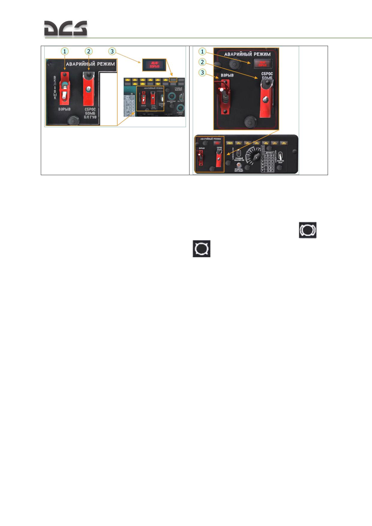
1. The ВЗРЫВ (ARMED) switch - in the ВКЛ (ON,
1. Signal panel, indicating that bombs were
up) position arms bombs;
emergency armed.
2.The СБРОС БОМБ БЛ ГУВ (JETTISON BOMB
2. The СБРОС БОМБ (BOMB JETTISON) -
ROCKET GUV) spring loaded jettison switch -
springloaded jettison switch - when toggled to
when toggled to the upper position, opens all locks
the upper position, opens locks on external
on external hardpoints;
3. Signal panel, indicating that bombs were
hardpoints with the following symbols
or
emergency armed.
;
3. The ВЗРЫВ (ARMED) switch - in the ВКЛ
(ON, up) position arms bombs
That is why emergency jettison can be performed from pilot’s or co-pilot’s place.
Jettison can be performed with armed or non-armed bombs, depending on positions
of the “ВЗРЫВ” (ARMED) switches on weapons control panels. In the “ВЗРЫВ”
(ARMED) position, bombs will be armed and explode when they touch the ground.
In case of emergency jettison from pilot’s place, all stores will be jettisoned
independently on store types, but if emergency jettison is performed from co-pilot’s
place, only bombs will be jettisoned, if they are present in the table on the bomb
armament panel, see Table 12.11.
374
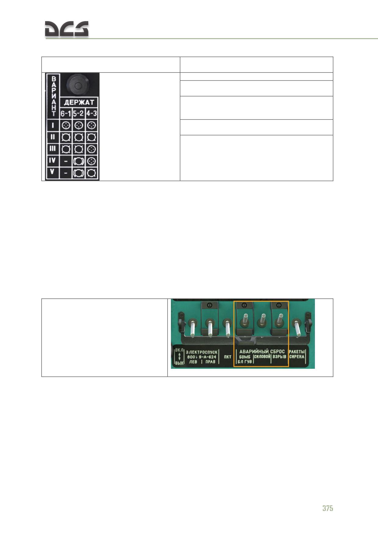
DIGITAL COMBAT SIMULATOR Mi-8МТV2
Table 12.11
Payload profiles
What will be jettisoned by the co-pilot
(on co-pilot’s bomb armament panel)
I - "all rocket launcher" - nothing will be jettisoned
II - "all bombs" - jettison impulse is send to
external hardpoints №1-6 simultaneously
III - "bombs- rocket launchers" - jettison impulse
is send to external hardpoints №1, 6, 2, 5
simultaneously
IV - "bombs- rocket launchers" - jettison impulse is
send to external hardpoints №2, 5 simultaneously
V - "all bombs" - jettison impulse is send to
external hardpoints №2, 5, 3, 4 simultaneously
When the rotating switch ВАРИАНТЫ ПОДВЕСКИ (PAYLOAD PROFILE) on the
bomb armament panel is in the I, III and IV positions, the rocket launchers will not
be jettisoned by the co-pilot with help of emergency jettison circuits.
Rocket launchers in those cases can be jettisoned by the pilot with help of the
СБРОС БОМБ БЛ ГУВ (JETTISON BOMB ROCKET GUV) switch on the pilot’s weapon
control panel. If it is necessary to jettison everything by the co-pilot, switch the
payload profile selector into positions II or V (in this case system will assume that
bombs are present on all hardpoints).
12.5.2. Emergency jettison procedure for the pilot
To emergency jettison stores, pilot must check and perform the following actions:
1. ACBs on the left circuit breaker
panel must be enabled (only those,
needed for jettison, are shown)
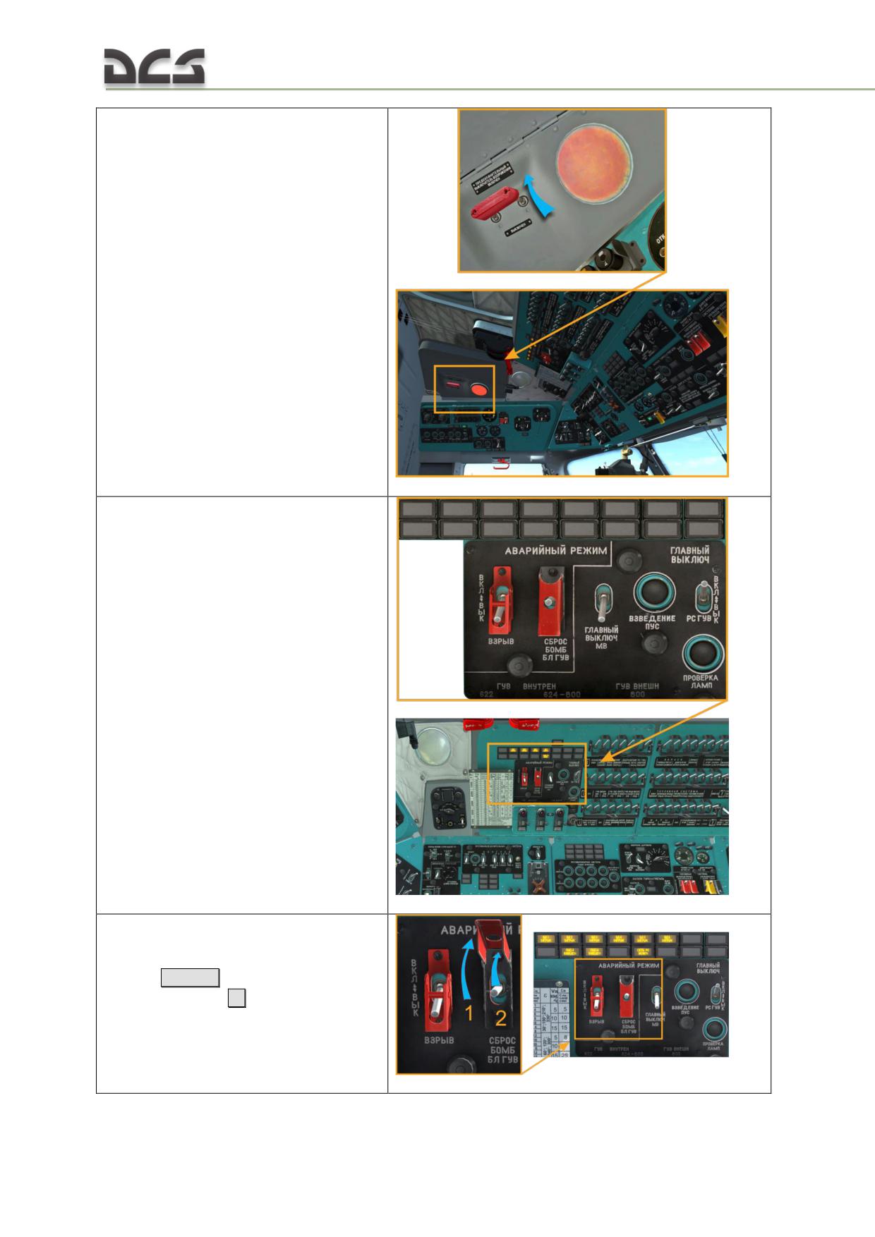
2. MASTER ARM SWITCHES must be
enabled.
3. On Upper armament Control
Panel:
a) if it is necessary to jettison
non-armed bombs, open the
safety cover of the jettison switch
[Lalt + J]
(1) and perfrorm
jettison
[J]
(2)
376
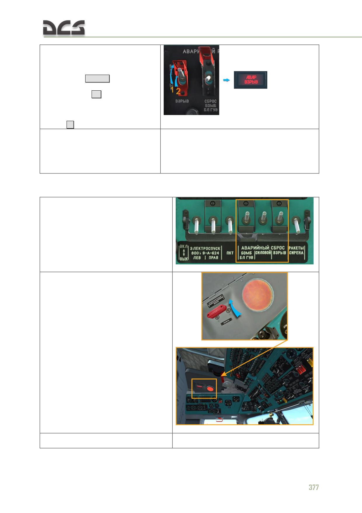
b) if it necessary to perform
jettison of armed bombs, then
it is necessary to open safety
cover of the ВЗРЫВ (ARMED)
switch
[Lalt + J]
(1), and set this
switch to the ВКЛ (ON, upper
position)
[H]
(2), as a result
signal panel АВАР ВЗРЫВ
(JETTISON ARMED) goes on,
after that perform jettison
[J]
, see a).
4. Make sure that bombs, rocket launcher
and containers were jettisoned and
corresponding signal lights went off;
5. Set the СБРОС БОМБ БЛ ГУВ
(JETTISON BOMB ROCKET GUV) switch to
the ВЫКЛ (OFF) position.
12.5.3. Emergency jettison procedure for the co-pilot
1. ACBs on the left circuit breaker
panel must be enabled (only those, needed
for jettison, are shown)
2. MASTER ARM SWITCHES must be
enabled.
3. On the Bombs control panel:
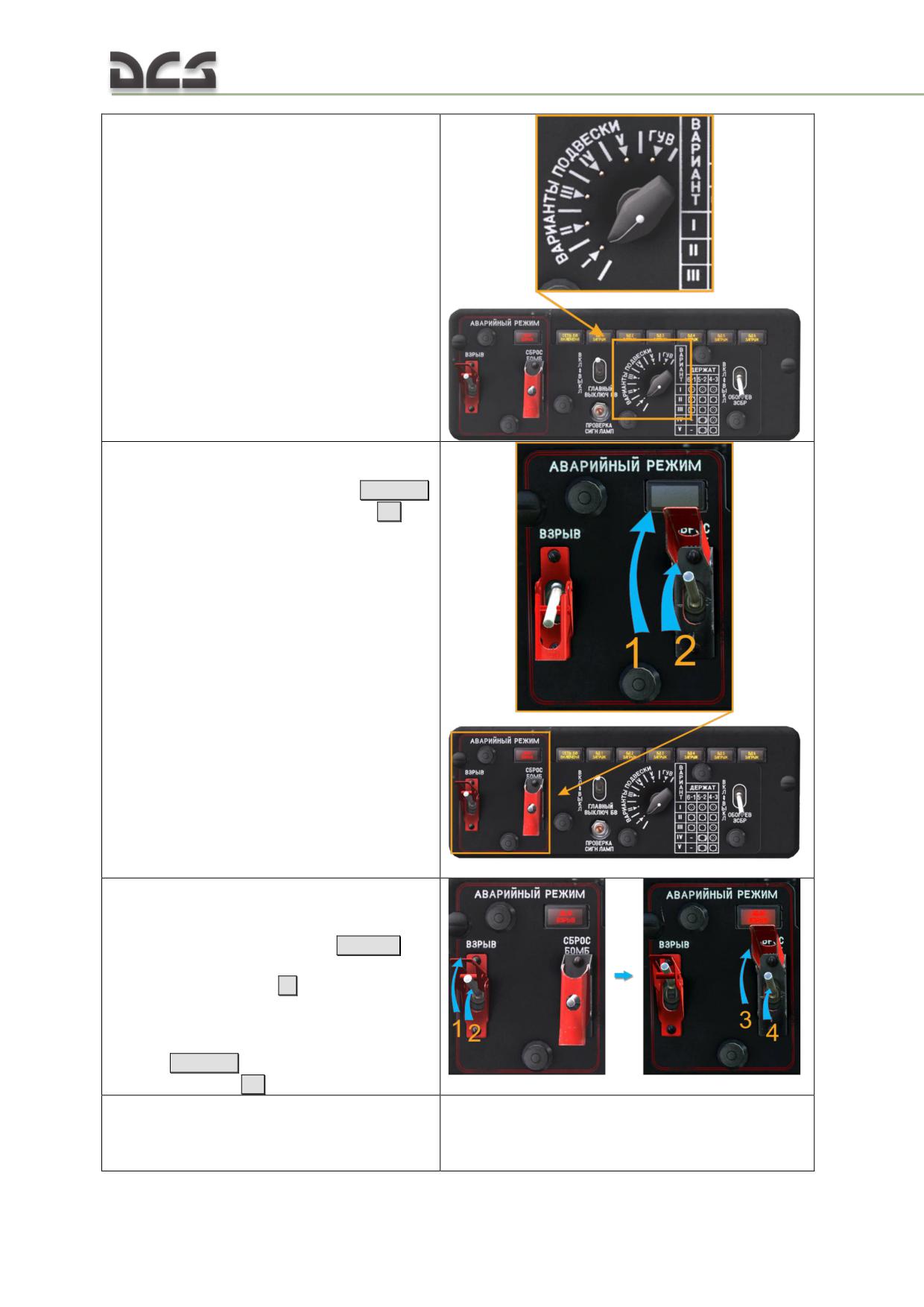
a) check selected weapon profile, see
Table 12.11
b) if it is necessary to jettison non-
armed bombs, open the safety
cover of the jettison switch
[Ralt + U]
(1) and perfrorm jettison
[U]
(2)
c) if it necessary to perform jettison
of armed bombs, then it is
necessary to open safety cover of the
ВЗРЫВ (ARMED) switch
[Ralt + I]
(1),
and set this switch to the ВКЛ (ON,
upper position)
[I]
(2), as a result
signal panel АВАР ВЗРЫВ (JETTISON
ARMED) goes on, after that open the
safety cover of the jettison switch
[Ralt + U] (3) and perfrorm
jettison
[U]
(4)
4. Make sure that bombs were jettisoned and
corresponding signal lights went off;
5. Set the СБРОС БОМБ (JETTISON BOMB)
switch to the ВЫКЛ (OFF) position and close it
378
with the xsafety cover.
13
SPECIAL TASKS
DIGITAL COMBAT SIMULATOR Mi-8МТV2
13.
SPECIAL TASKS
13.1. Sling load operations
Sling load operations are implemented in the game, see Fig. 13.1
Description of Sling load equipment see 7.10
Fig. 13.1. Mi-8MTV2 is flying with a sling load
The most demanding stages of the external load operations are:
hovering over the load and hookup;
taking off with the load;
transportation of cargo to the required area;
approaching and hovering over the unhook point, load unhook.
In real life flights with a sling load are the most difficult ones. During such a flight
crew is working very intensively. To partly compensate lack of the crew assitstance,
in this game several features, for sling load operations, were implemented. They can
be activated by the player, or automatically, see below.
In addition, to play with a sling load, corresponding mission with cargos (loads),
which belongs to player’s coalition, must be created in mission editor.
13.1.1. Game features, related to sling load operations
These features are intended to help player to hover precisely (position and altitude)
above the cargo for hooking it up, as well as to assist during flight to designated
area, approaching and hovering over the unhook area. These features are:
smoke marking of the cargo from certain distance (2000 m), this feature
is active, when cargo has been selected from the radio menu.
external cargo indicator, which indicates position of the cargo relative to
the cargo hook, as well as position of the helicopter, during hovering
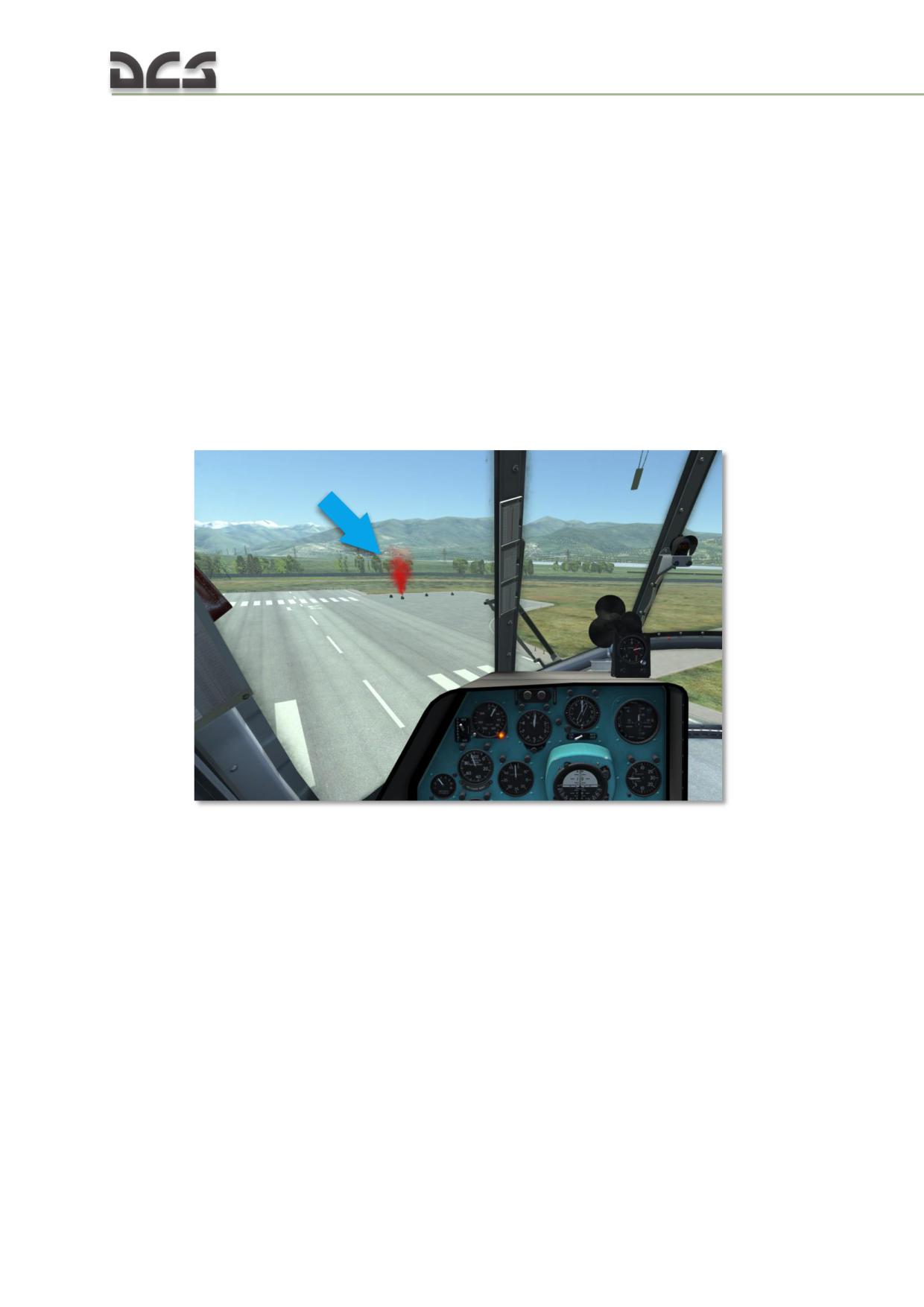
above the cargo. This feature is engaged by the player and is working
during hook up stage.
automatic voice assistant (AI crew chief), which guides pilot where to and
at which distance pilot must move helicopter to achieve presise hover over
the load. This feature is automatic and is active during the following
stages: hooking up the cargo, taking off with the cargo, flight to
designated area, unhooking the cargo (if mission was properly prepared).
Feature activation, see below;
view from the helicopter’s blister on the cargo (down, under the
helicopter), which makes hovering over the cargo easier. This feature is
activated manualy by the player, works unconditionally.
Cargo smoke marker, (see Fig. 13.2 ). It appears automatically, after the cargo
was selected via radio menu (see, below). Cargo smoke marker is seen only by
player, who selected corresponding cargo (in multiplayer missions).
Fig. 13.2. Cargo smoke marker
External cargo indicator, Fig. 13.3.
382
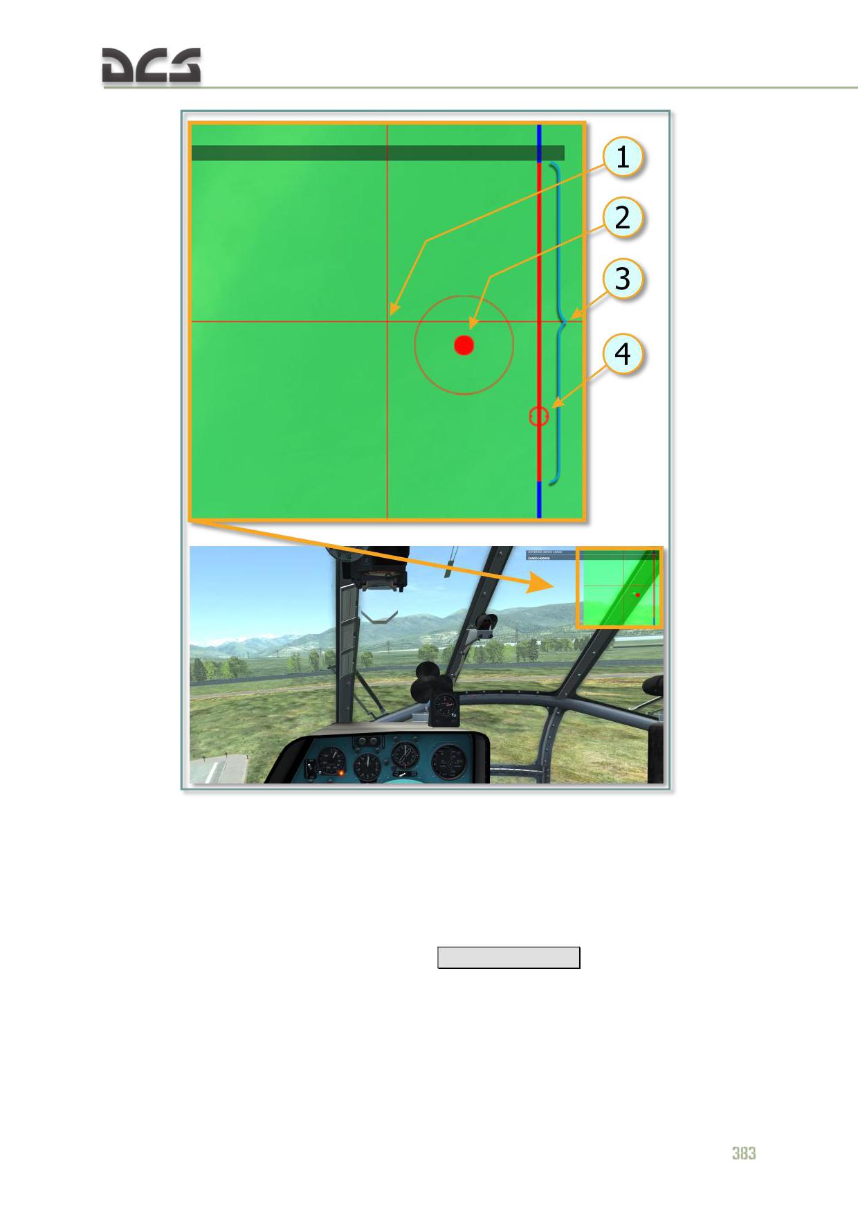
Fig. 13.3. External cargo indicator
1. Projection of the cargo hook on the
3. Allowed hoveraltitude range
surface
4. Indication of helicopter’s altitude relative
2. Cargo position
to the allowed altitude range (any position
on the red line is ОК)
Activation/deactivation of this indicator can be done after the desired cargo is
selected using radio menu by pressing the [
RCtrl + Rshift + P]
combination.
Automatic voice assistant (AI crew chief RU or EN) by giving voice command,
helps:
while hovering over the cargo for hooking it up - is giving commands,
which help to position the helicopter precisely above the cargo, informs
when cargo is hooked up;

while taking off with a sling load - is informing about cargo condition and
it’s altitude off the ground;
while flying to the designated area - is informing about cargo oscillations,
and if cargo is lower than 60 meters above the ground;
while hovering over the unhook point/ drop zone (if this point is created in
mission editor, see below), is giving commands to position the helicopter
over the unhook point, informs, when cargo touches the ground.
While hovering above the cargo, the AI crew chief engages, when distance to the
cargo is less then 10 m. on X,Y,Z (i.e if at least one of the distances is less than 10
m.). While approaching unhook point, the AI crew chief engages if distance from
cargo to center of the unhook point is less than 50 meters. Commands, given by the
AI at different stages of flight, are listed in Table 13.1.
Table 13.1
Flight stage, description of the situation,
guiding where to move the helicopter, various
Phrases of the AI crew chief (numbers are
information
meters)
Hovering over cargo
up - meter (2, 3, 5, 10, 15, 20, 30, 50, 60, 100,
increase your altitude at ..
150)
down - meter (2, 3, 5, 10, 15, 20, 30, 50, 60,
decrease your altitude at ..
100, 150)
move forward at ..
forward - meter (2, 3, 5, 10, 15)
move backward at ..
back - meter (2, 3, 5, 10, 15)
move left at ..
left - meter (2, 3, 5, 10, 15)
move right at ..
right - meter (2, 3, 5, 10, 15)
Hooking up a cargo
helicopter is hovering precisely over the load
in position
load is hooked and hook lock is locked
automatically (or manually by pressing
corresponding key combination)
load is hooked
smoothly tighten the slings
slings are coming tight
slings are tight
slings are tight
helicopter is hovering at required altitude over
the load (altitude is equal to sling length +
load height)
at altitude
keep required altitude (altitude is equal to sling
length + load height)
hold this altitude
Takeoff with a sling load
Load is still on the ground
load is on the ground
Load is lifted at one meter off the ground
load is one meter off the ground
Load is lifted at three meters off the ground
three off the ground
Load is lifted at five meters off the ground
five off the ground
Sling load’s behavior in the air is normal, as
expected, pilot can start accelerating
Load is cleared for flight
Load is at ten meters off the ground
ten off the ground
Load is at fifteen meters off the ground
fifteen off the ground
Load is at twenty meters off the ground
twenty off the ground
384

Flight to the designated area (drop
zone)
The load is swinging fore and aft
the load is swinging fore and aft (3, 5, 10, 15, 30)
The load is swinging side to side
the load is swinging side to side (3, 5, 10, 15, 30)
Swinging of the load disappeared (eliminated)
load is hanging steady
Load is at (60, 50, 30, 20, 15, 10, 5, 3, meter)
(60, 50, 30, 20, 15, 10, 5, 3, meter) of the
off the ground
ground
Approaching and hovering over drop
zone, load unhook (if trigger is used to
mark the drop zone)
Load is at (60, 50, 30, 20, 15, 10, 5, 3, meter)
load is (60, 50, 30, 20, 15, 10, 5, 3, meter) off
off the ground
the ground
increase your altitude at ..
up - meter (2, 3, 5)
decrease your altitude at ..
down - meter (2, 3, 5)
move forward at ..
forward - meter (2, 3, 5, 10, 15, 20, 30, 50)
move backward at ..
back - meter (2, 3, 5, 10, 15, 20, 30, 50)
move left at ..
left - meter (2, 3, 5, 10, 15, 20, 30, 50)
move right at ..
right - meter (2, 3, 5, 10, 15, 20, 30, 50)
helicopter hovers precisely over the drop zone
(±2,5 m)
in position/ over drop zone
load is on the ground, unhook the load
on the ground, release
In case if load is to be released at drop zone/unhook zone without trigger, the voice
assistant will help to control altitude of load above the ground with the following
phrases: “60 off the ground”, “50 off the ground”, “30 off the ground”, “20 off the
ground”, “15 off the ground”, “10 off the ground”, “5 off the ground”, “3 off the
ground”, “meter off the ground”, “on the ground, release”.
After the “on the ground, release” phrase, the automatic voice assistant (AI crew
chief RU or EN) stops functioning, until the next load is selected.
Keep in mind that during vigourous maneuvers in hookup or drop zone (altitude and
position), information, given by the AI crew chief, quickly became outdated.
View from blister on the cargo (Fig. 13.4) is used to control hovering position,
when normal view on the cargo is blocked by the fuselage, is activated/deactivated
by the [
Lshift + Lalt + С]
keys,
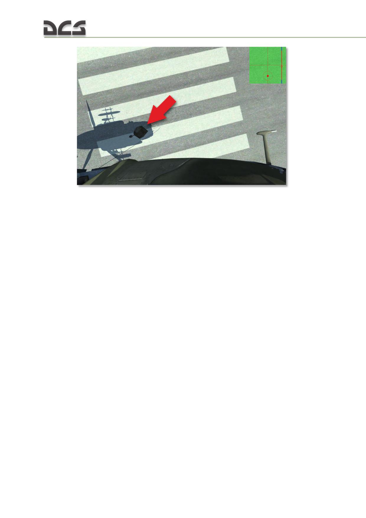
Fig. 13.4. View from the blister on the cargo
View from the blister is implemented from both pilot’s and co-pilot’s places.
It is highly recommended to assign this view on one of the joystick’s buttons and use
for a short periods of time while hovering over the cargo.
13.1.2. How to prepare a flight mission with a sling load
Placing cargo on map and adjustment of the sling length
To create a sling load mission, player must follow the flow chart below
(see Fig. 13.5 ):
386
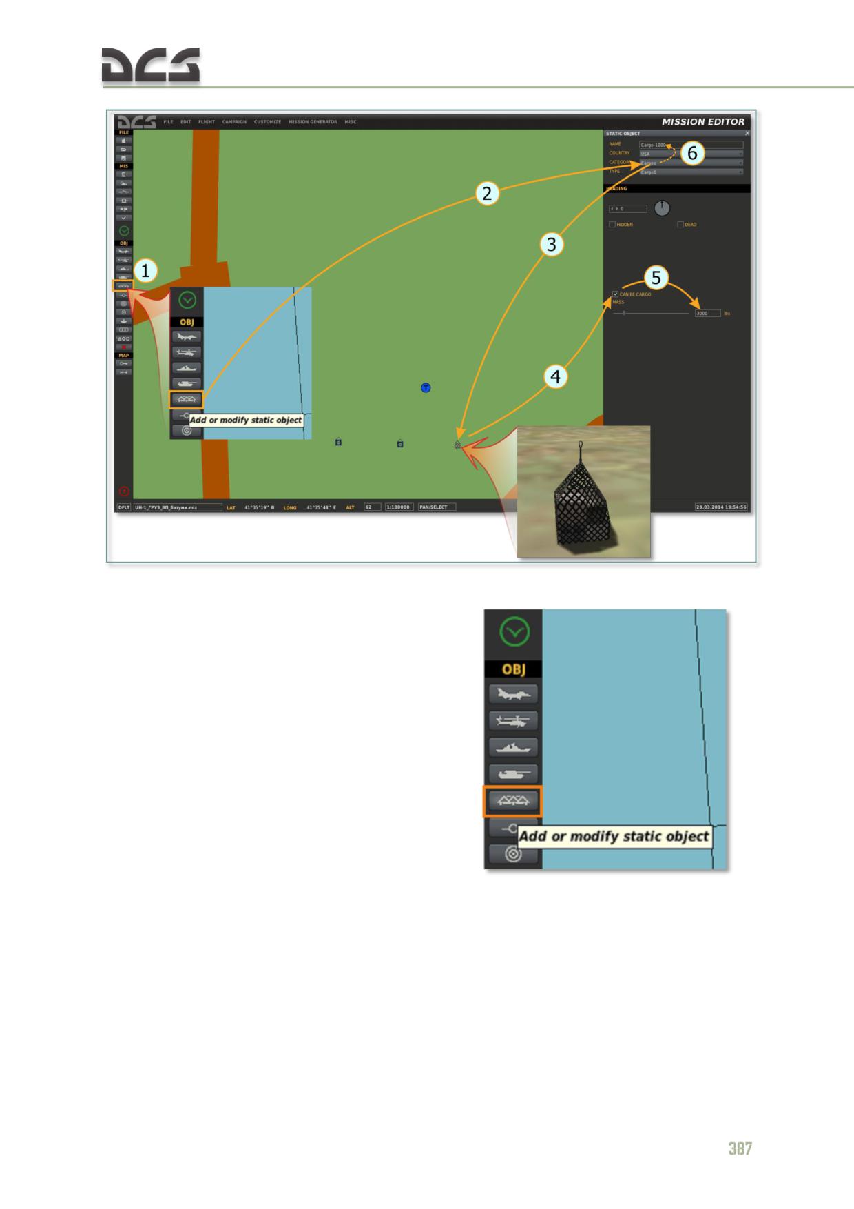
Fig. 13.5 Flow chart explaining creation of the mission with a sling load
1. Press the “Add or modify static object”
;
2. Select the CATEGORY - "Cargos" from the drop-down list, TYPE - "Cargo-
1 (or xx)":
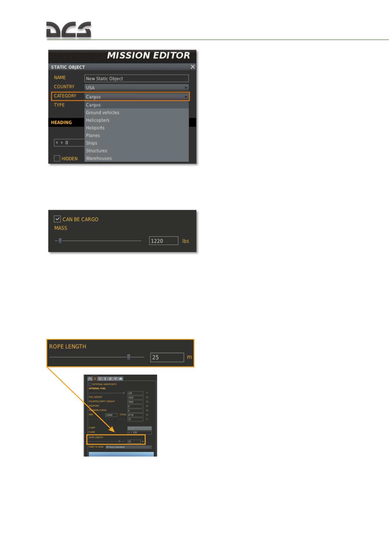
3. Place the cargo on the map (left button click);
4. Set the “CAN BE CARGO” flag (this allows this cargo to be selected and
hooked up):
5. Set the required cargo weight (if available weight change), for beginners,
around 500kg (1100lbs) is recommended;
6. Rename this object (cargo) (recommended), for example "LOAD-500" or
"CARGO-1300". It makes selection of the desired cargo, using radio menu,
easier.
7. Adjust the length of the rope (maximum 30m), for beginners 10-15m is
recommended:
8. Save the mission, this concludes mission creation.
388
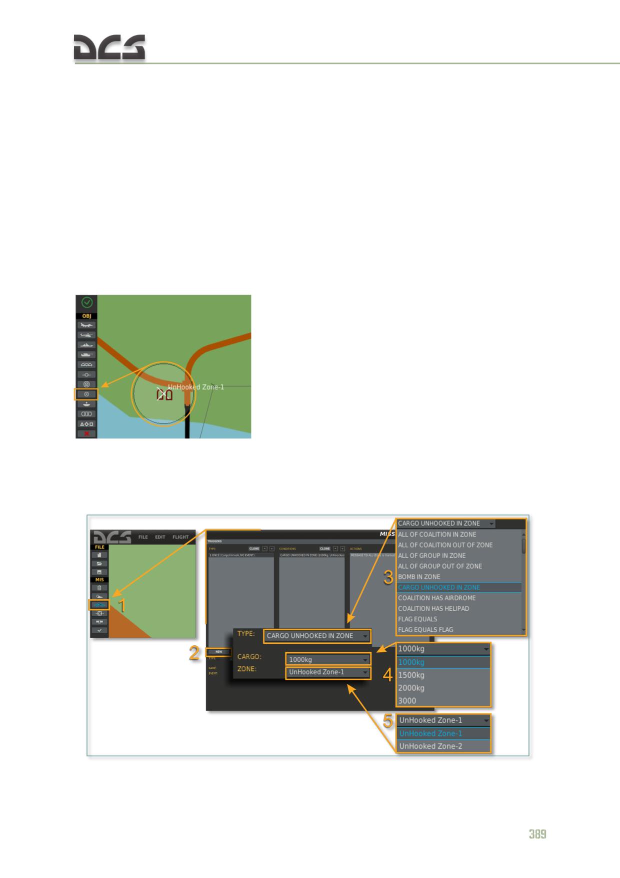
Created, in this way mission, allows player to hook up the cargo, transport and
unhook the cargo at any place (unhook zone is not designated and thus smoke
marking of the unhook zone and AI crew chief will not be functional).
To create a more advanced mission, where player must unhook cargo precisely at
designated area, using advanced features like marking of the unhook zone with a
smoke and AI crew chief assistant, a trigger area of the unhook zone type must be
added.
Creation of the unhook zone
To have a possibility of marking the unhook zone with a smoke and use the
automatic voice assistant (AI crew chief, see below), is necessary:
1. Place a trigger zone, give it a name and set the desired radius (in this case
length of the radius does not matter):
2. In the “TRIGGERS” tab Fig. 13.6 (1) create a new trigger (2); select from the
drop-down list the CARGO UNHOOKED IN ZONE (3) condition; select cargo,
which must be unhooked at this zone (4) and link the selected cargo with the
unhook zone (5):
Fig. 13.6. Creation of the unhook zone
3. In the action tab, player must select some actions to be performed when
cargo is unhooked, for example, give a message “Gargo is unhooked at
designated area”. In the opposite case the trigger will not be saved.
Now, while approaching drop zone with a “1000kg” cargo, at a distance of less than
2 km from center of the “UnHooked Zone-1”, unhook area will be marked with the
smoke and from 50m the AI crew chief, will be giving guiding commands to achieve
precise hover over the unhook place. Many different cargos can be linked to one
trigger zone.
13.1.3. Playing with sling loads
Let us give you an example, showing selection of a load and various flight stages.
In certain area are several loads with different weight. Player must select one of
them, hover over the selected load to hook it up, take off with the sling load, fly to
designated area, approach drop zone and hover to unhook the load.
PLAYERS ACTIONS
Cargo selection
To give player an opportunity to select cargo (using radio menu), “cargo visibility
zone” is implemented. This zone is moving together with helicopter, flown by player
or bot (zone is shown as circles around helicopters №1 and 2). Therefore, cargos
can be selected by player only if helicopter is close enough to them, so that distance
to a cargo is less than the “cargo visibility zone” (see, Fig. 13.7, helicopter №2)
390
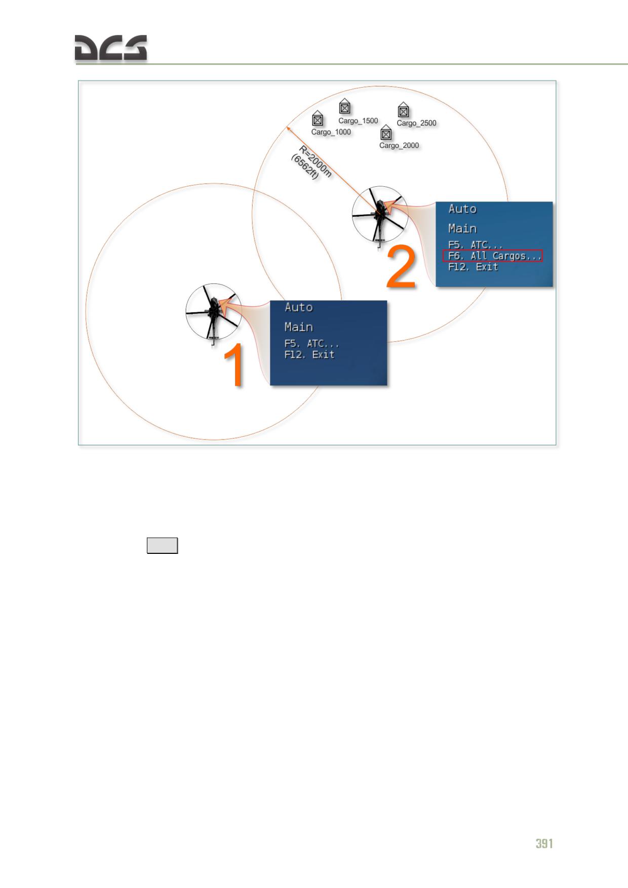
Fig. 13.7. Explanation of how cargos appear in the radio menu
Based on experimental results, radius of the cargo detection zone is set to 2000 m
(6,562 ft). If helicopter is more than 2000 m. from the cargo, it cannot be selected
(helicopter №1). As soon as cargo is in the “visibility zone”, which is moving together
with the helicopter, then in radio menu additional entry for cargo selection page,
activated by
[F6] ,
will appear (helicopter №2).
When cargos are in detection zone, player can select the desired cargo from the list
(see, Fig. 12.9).
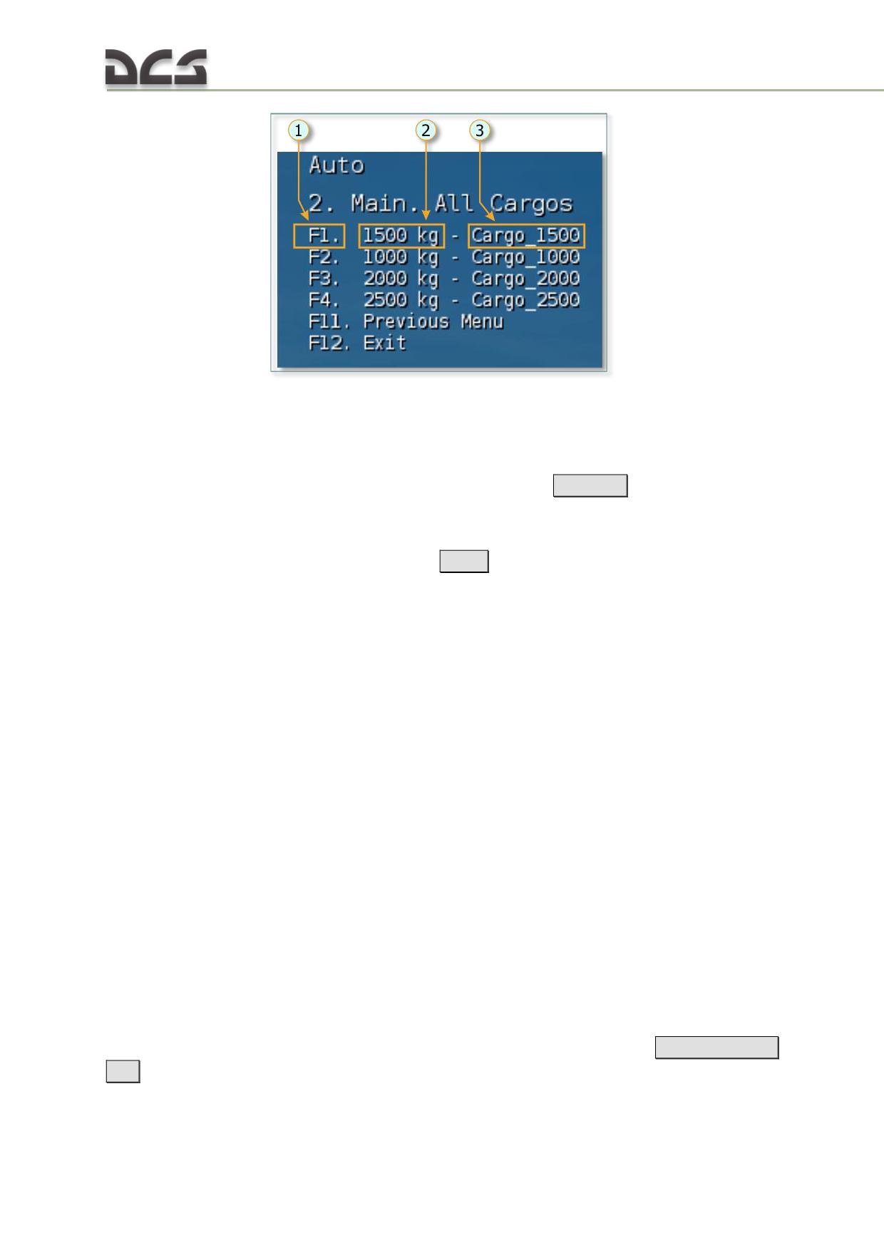
Fig. 13.8. Cargo selection list
1. Key, selecting corresponding cargo
3. Cargo name
2. Cargo weight
To select desired cargo player must press one of the
[F1..F10]
keys. As a result,
cargo location will be immediately marked with a smoke.
If necessary, player can change selected cargo, to do that, one must activate radio
menu, select the cargo selection page
[F6] and choose CANCEL for previously
selected cargo. Then the cargo selection procedure, explained above, must be
repeated for a new cargo.
Hovering and hooking up the load
A cargo can be hooked up by the AI (i.e. automatically) or by the player in “manual
hook up” mode.
AUTOMATIC CARGO HOOKUP is activated once cargo is selected using radio menu. It can
be done only by hovering above the cargo. Automatic hookup can only be successful
if the following conditions, such as, sling length, precision of hover and time that is
required by a virtual ground operator for hooking up the cargo, are fulfilled.
Therefore, to hook up the cargo, pilot must hover within limited area and remain
there within given period of time. Hover zone limitations:
relative to longitudinal and lateral axes - radius 2.5m;
relative to vertical axis - from “load height + 0.5m” to “sling length + load
height - 0.5 m”. For example, if sling length is 30 m, and load height is
7m, than allowed altitude range (above ground level) for hooking up the
cargo is: from 7+0.5m (7.5 m) to 30+7-0.5 (36.5 m).
Helicopter must hover in this zone for not less than 5 s.
Sling length can be from 5 m to 30 m.
When cargo is selected, the external cargo indicator can be activated
[Rshift + RCtrl
+ P]
392
At a distance of 10 m to selected cargo (any axis) automatic voice assistant is
engaged.
While helicopter is hovering precisely over the cargo (all conditions are fulfilled), the
IN POSITION/ HOVER ABOVE CARGO message is being shown and after 5 s the
LOAD IS HOOKED/ CARGO HOOKED appears. If player leaves required zone, the
corresponding message will be given.
“MANUAL CARGO HOOKUP”. Used if player has landed nearby the load, selected from the
menu. “Manual hookup” works only if helicopter is close enough to the selected load
and if sling length is longer than the distance from landing place to load attachment
point, to hook up press the
[RCtrl + Rshift + L]
. Successful hookup is confirmed by
the text message and by voice assistant.
Take off with a sling load
When the cargo was hooked up, one must, gradually, without rush, increase altitude
to tighten up the sling. When the sling is tighten, raise the collective and vertically lift
the cargo off the ground. Further, continue climbing and do not go back to hover (do
not lower the collective), instead, gradually begin accelerating the helicopter,
continuing climbing. Push the stick forward very carefully, exceeding of pitch of
more than
1-2° is not recommended. During take off the voice assistant is
continuing operating.
While accelerating, do not allow reduction of vertical speed to less than zero. Take
into account additional altitude slack, while flying over obstacles.
Flight to designated area (drop zone)
While flying, monitor if cargo is swinging, and if cargo is swinging heavily, try to
compensate swinging by slightly lowering the collective when cargo begins moving
from one of the end positions to the center. Avoid sharp and abrupt movements of
the stick and collective for changing flying mode. When cargo is swinging or cargo is
less than 60 m above the ground, player will be informed by the voice assistant.
Approach and hover over the drop zone, cargo unhook
Approach the designated drop zone. Reduce speed in advance (1,600- 1,400m),
deceleration rate should be significantly lower than under normal conditions, without
sling load.
If the drop zone was created with a trigger, then when helicopter approaches drop
zone with a sling load, from distance of 2 km drop zone will be marked with a
smoke. From 50 m to this zone, voice assistant begins guiding you to help achieving
perfect hover and will inform you when the load touches the ground.
Before unhooking the cargo, the “auto unhook” feature (see Automatic cargo
unhook) can be activated, by pressing the
[RCtrl + Rshift + K]
. It will immediately
unhook the load, as soon as it touches the ground. Player can unhook load manually
as well. When cargo is at desired place on the ground, press the external cargo
tactical unhook button or external cargo emergency unhook button, located on the
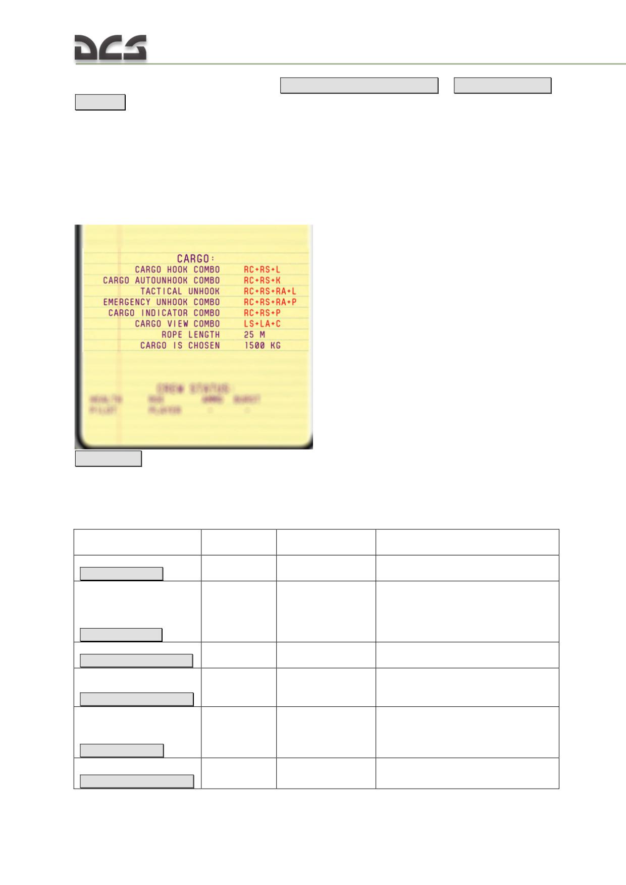
collective (Fig. 7.43) by pressing the
[RCtrl + Rshift + Ralt + L]
or
[RCtrl + Rshift +
Ralt + P]
When cargo hook is opened, the corresponding message is given.
13.1.4. Informational help to player, related to sling load operations
During playing the game, player can get some hints, which remind player about
useful key combinations, rope length, and which cargo is chosen and hooked up.
Player must open kneeboard to see these hints,
[Rshift + K]
More about kneeboard features you can find in chapter 14.7.
13.1.5. Keyboard commands, related to sling operations
Назначение
Key combination
на русском
Function
Comments
Индикатор
External Cargo
Enables/disables external cargo
RCtrl + Rshift + P
груза
Indicator
indicator (cheat)
When pressed, hooks up the load, if
the helicopter is on the ground and
Подцеп
External Cargo
sling length is long enough to reach
RCtrl + Rshift + L
груза
Hook
load’s attachment point.
Тактический
External Cargo
RCtrl + Rshift + Ralt + L
отцеп груза
Tactical Unhook
Safety cover opens immediately
External Cargo
Аварийный
Emergency
RCtrl + Rshift + Ralt + P
отцеп груза
Unhook
Safety cover opens immediately
Activate/deactivate autounhook
Автоматичес
External Cargo
feature, load is unhooked if cargo
кий отцеп
Autounhook
touches the ground and force,
RCtrl + Rshift + K
груза
Switch - ON/OFF
applied to cargo hook is removed
Открытие/за
External Cargo
RCtrl + Rshift + Ralt + T
крытие
Tactical Unhook
394
колпачка
Button Cover
для кнопки
OPEN/CLOSE
"Тактически
й сброс
груза"
Открытие/за
крытие
External Cargo
колпачка
Emergency
для кнопки
Unhook Button
"Аварийный
Cover
RCtrl + Rshift + Ralt + R
сброс груза"
- OPEN/CLOSE
External Cargo
Тактический
Tactical Unhook
Triggers only if safety cover is
RCtrl + Rshift + Ralt + Q
отцеп груза
Button
opened
External Cargo
Аварийный
Emergency
Triggers only if safety cover is
RCtrl + Rshift + Ralt + A
отцеп груза
Unhook Button
opened
Slowly changes normal view to view
Взгляд на
to the open blister, works differently
Lshift + Lalt + С
цель
View to Aim
for pilot’s and co-pilot’s places.
DIGITAL COMBAT SIMULATOR Mi-8МТV2
14. HOW TO PLAY
To Important notice
14.1. General information
This game is a first-person aircraft simulation, where the player controls an
helicopter and interacts with cockpit objects with the help of various game controllers
(joysticks, pedals, touchpads, etc.), keyboard and mouse.
It is possible to set an external camera (relative to the helicopter’s cockpit) in any place of the game
world to observe the player’s helicopter and other objects in the world.
The simulation gives the player the unique opportunity to control an helicopter in
real-time in the same way a real pilot does. The player has to interact with cockpit
objects, distribute his/her attention between the cockpit and the outside world at
every stage of the flight - from engine startup to taxiing to the parking spot after
landing. In addition, there are scenarios where the player has to interact with and
give orders to wingmen (player’s squadron pilots).
The game can be played in single-player mode (the player is alone in the simulated
world, everything else is controlled by the AI) or in multiplayer mode (there are
several human players connected via the internet, other objects are controlled by the
AI).
When a module is purchased, it has to be installed and activated as a module to DCS
World. The main documents, describing the activation procedure, the main window
functions, game settings, mission editor, and the setup of game controllers are
located in the “Doc” folder inside the game installation directory. Each document
describes a certain game functionality:
a) how to install and activate the game -
DCS World Activation Guide EN.pdf;
b) the main game window and mission editor functionality -
DCS User Manual EN.pdf;
c) setup of game controllers -
DCS World Input Controller Walk Through EN.pdf;
d) Airfields radio equipment and beacons -
DCS World List of all available Beacons EN.pdf.
For a player to find himself in the cockpit it is necessary to start relevant mission
(scenario) under control of the DCS World shell. Missions can be built-in in the game
(supplied with the module installation package), downloaded from the internet or
developed independently. A set of related missions is called a campaign. The user
can create a mission (campaign) by himself, using the MISSION EDITOR (ME) tools.
Usage of the mission editor is described in the document DCS User Manual EN.pdf.
Interaction between player and virtual cockpit
Inside the cockpit, the player can control the aircraft, cockpit objects and
virtual pilot head position (views). All these functions can be implemented by
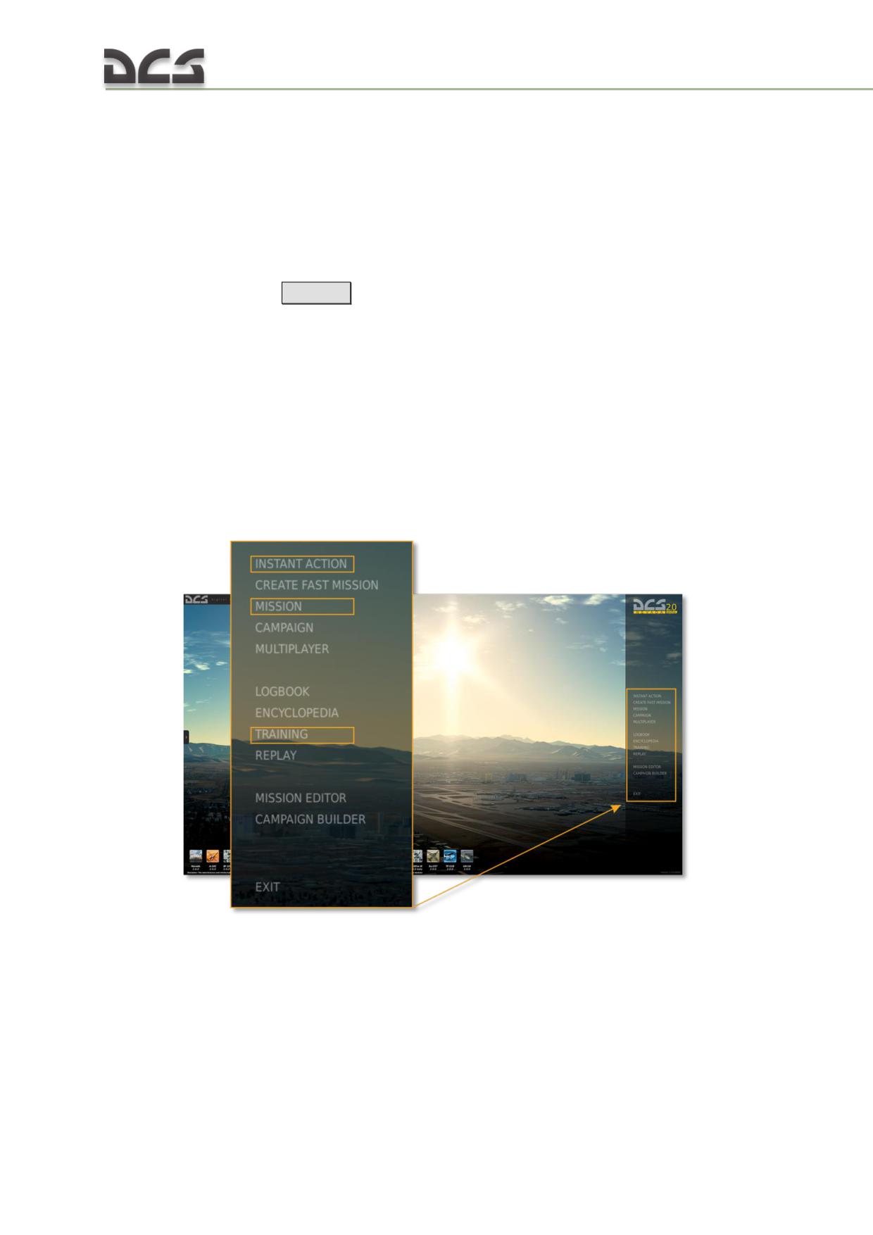
means of keyboard only, mouse, joystick or by their various combinations. It is
recommended to use a joystick for controlling the aircraft for the best possible game
experience.
The mouse can be used in the following two modes:
control various objects in the clickable cockpit;
control virtual pilot head position (view control, “mouse view”).
The player can switch between these two modes at any time by pressing the
keyboard combination
[Lalt+C]
or by a double-click of the mouse wheel.
14.2. Built-in missions
The game comes with a set of built-in missions: training missions, ordinary missions
and a campaign. Non-training missions (e.g. campaign) usually assume that the
player is already familiar with the helicopter and willing to try a scenario on his own.
Procedure for built-in mission start:
1. Start DCS World. When in the main menu, one can either start a training mission
by selecting TRAINING or ordinary missions by selecting INSTANT ACTION or
MISSION:
2. To choose a mission, it is necessary to select the desired module on the left and
then pick a mission from the corresponding folder (the example below contains the
folders "Taining", “QuickStart” and “Single”):
398
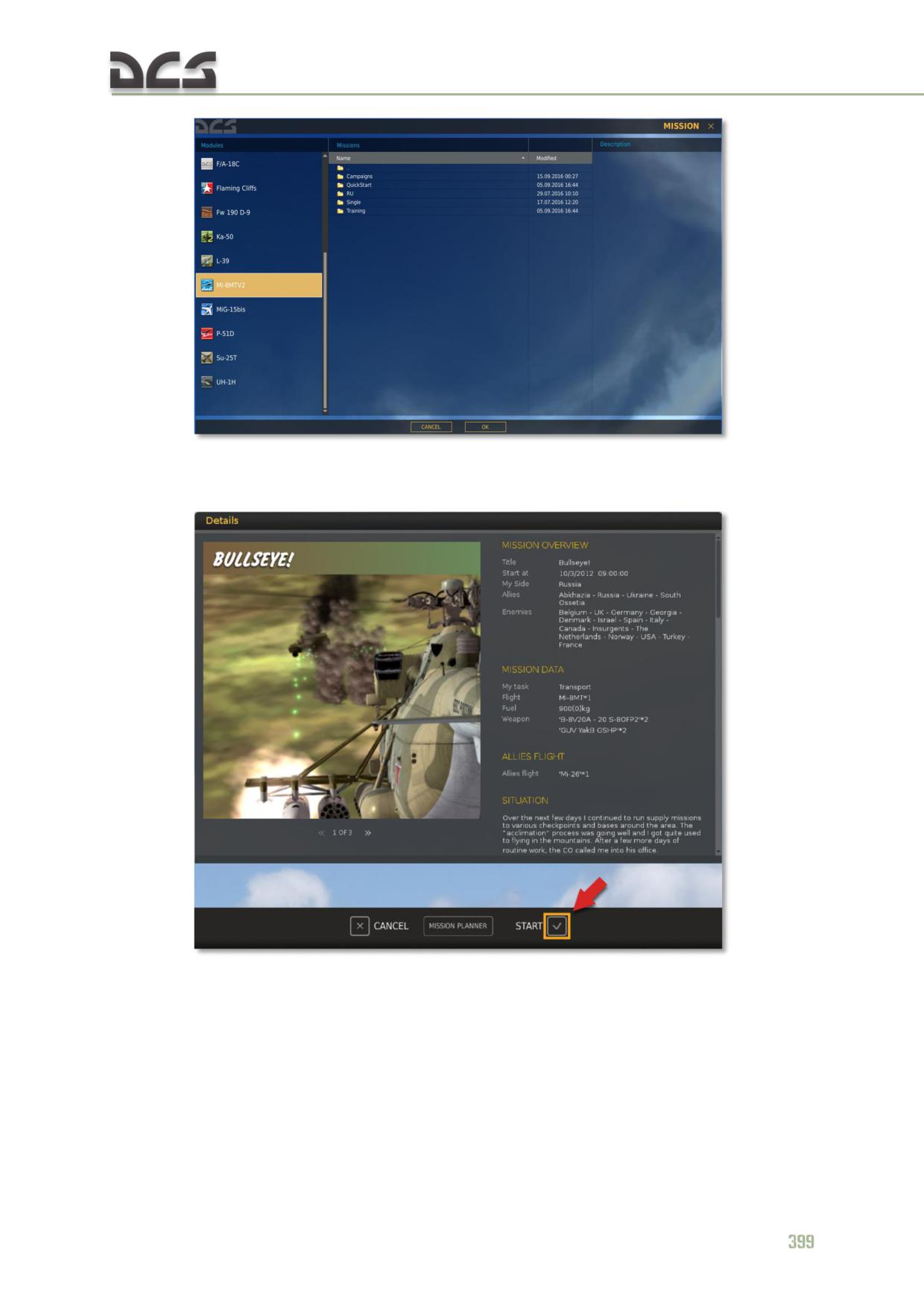
3. When the mission is selected, a briefing window with a START button, which is
used to start the mission, appears on the screen:
14.3. Controlling the helicopter and interacting with cockpit
objects in the game
The most essential helicopter’s controls include the aircraft control stick (for
helicopters it is a cyclic stick, for aircraft it is aircraft control stick), power control
lever (for helicopter it is a collective, which controls main rotor pitch and engines,
for airplane it is a throttle) and pedals. Cyclic (control stick) is used to control roll
(roll to the left or right) during turns, and pitch (nose up, nose down) during ascend
or descend, or in case of helicopter, to accelerate or decelerate helicopter. Collective
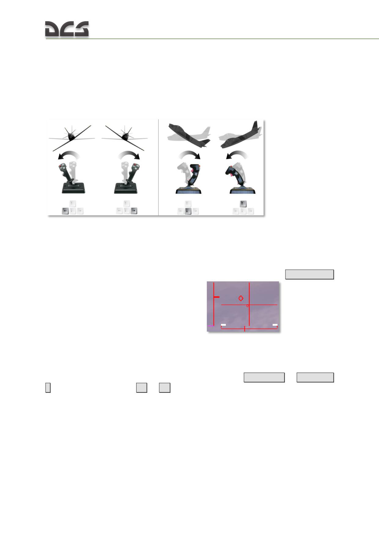
(throttle) is used when it is necessary to increase or decrease horizontal or vertical
speed. Pedals control yaw axis (turn of the plane nose to the right or left) and to
compensate slides with help of the rudder. Besides that, on the planes they can be
used, during taxiing, for braking main wheels separately to turn in the desired
direction (simultaneously with rudder deflection).
14.3.1. Controlling aircraft (airplane or helicopter) with help of a joystick
Roll
Pitch
Some joysticks are equipped with some lever or/and rotating knob (it can be any axis
of the joystick), which controls throttle (collective for helicopter) and a twister for
controlling pedals.
While piloting, it is possible to enable the controls indicator, using the
[RCtrl+Enter]
to see current positions of helicopter’s controls
14.3.2. Controlling helicopter with keyboard
If the player controls the helicopter using only the keyboard, the main control
buttons are: arrow keys to control cyclic (roll and pitch),
[Numpad+]
or
[Numpad-
]
for collective control and
[Z]
or
[X]
keys for pedals:
400
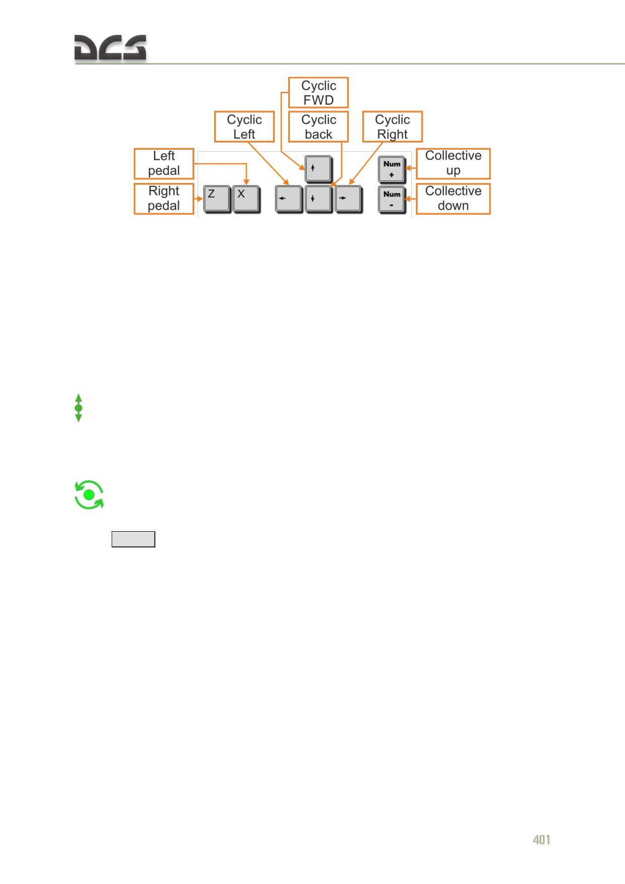
14.3.3. Interacting with cabin objects with the mouse
All objects of the clickable cockpit can be controlled by the mouse. This is the main
mouse mode in the game. The left and right buttons and the mouse wheel can be
used.
Normally, all switches are enabled by the left mouse button. The rotary switches
(rotating knobs with fixed positions) rotate with the left mouse button in one
direction
and
with
the
right
one
in
the
other.
Cockpit objects, which can be enabled or disabled with the mouse (when the mouse
pointer is over them), are marked with the following symbol:
Rotating knobs can be rotated with the mouse wheel. The cockpit objects, which can
be rotated when the mouse pointer is over them, are marked with the following
symbol:
To speed up the rotation of the knobs using the mouse wheel, it is necessary to
press
[Lshift]
while rotating the mouse wheel. This way the knob will rotate 10
times faster. By default, the mouse is in the “cockpit object control mode” described
above.
14.4. Controlling virtual pilot head position and views in the
6DOF cockpit
14.4.1. Controlling virtual pilot head position in the 6DOF cockpit
This implies that the head can be moved along the three axes (OX, OY, OZ), and
rotated around these axes (Fig. 14.1).
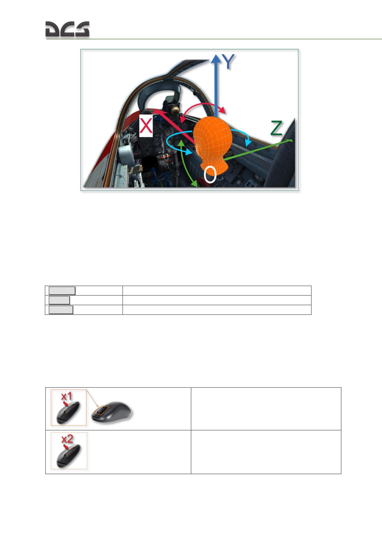
Fig. 14.1 Axes in the 6DOF cockpit
Head position may be controlled by all input devices: keyboard, mouse, joystick and
head tracking devices such as TrackIR. NOTE that virtual head rotation around the
OX axis (red color curved arrow) usually is not used, that is why it is unavailable for
controlling by means of keyboard and mouse.
In addition to head movement and rotation, there is also zoom feature (cockpit view
angle reduction).
The rate of view moving can be change:
Lshift + [
Mouse Rate Fast
Lalt + [
Mouse Rate Normal
LCtrl + [
Mouse Rate Slow
I.e. the working area of the screen displays only objects, which is inside the field of view. Because the
field of view becomes narrow during zooming, objects within the same area become larger. This can
be compared with the use of a telescope: all objects, located along the line of sight, are visible at any
magnification.
Head movement, rotation and image zooming with keyboard and
mouse
Symbols on schematics showing the mouse usage:
Click and hold the wheel pressed
Wheel double click
402
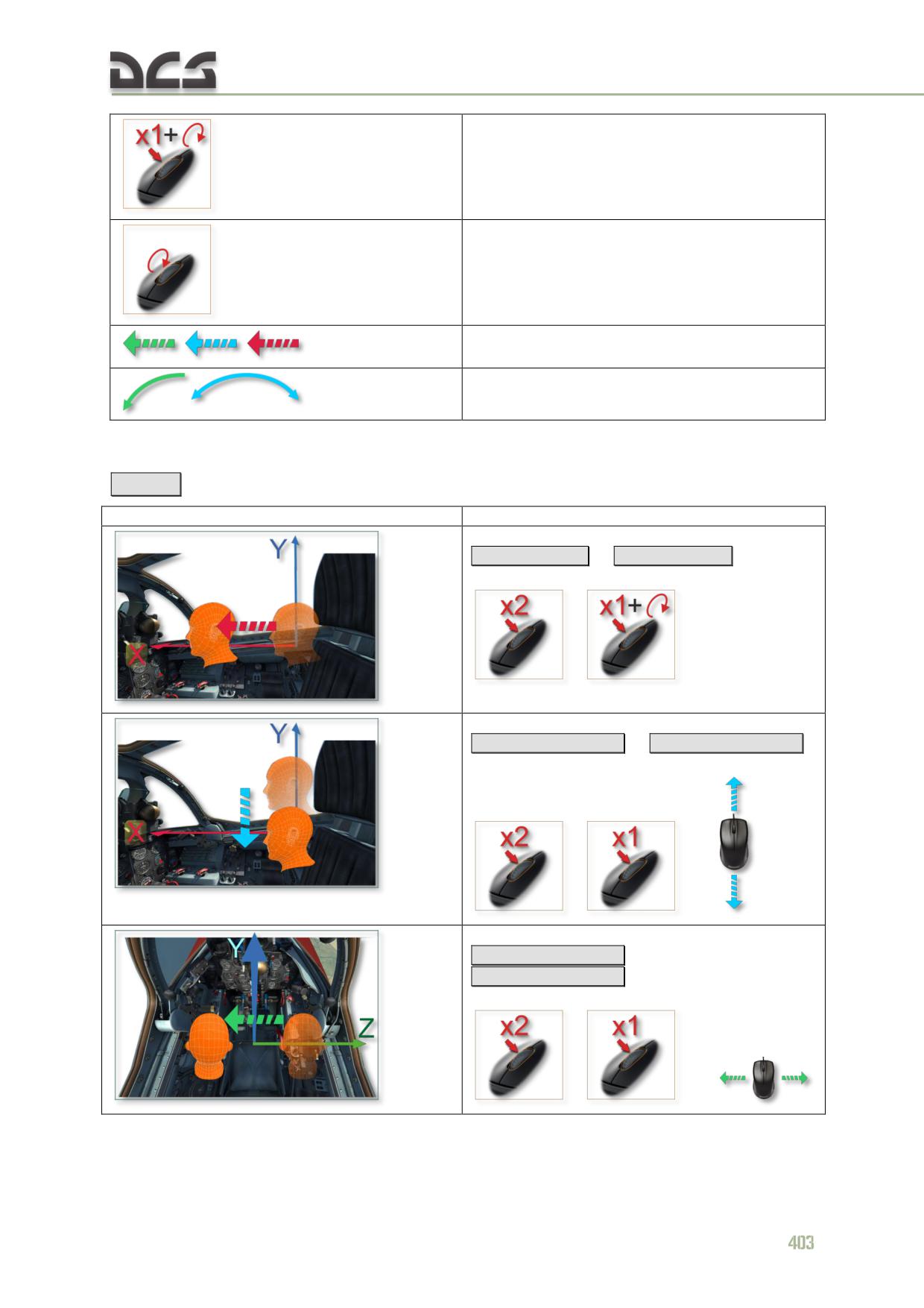
Click, hold the wheel pressed and rotate it
Rotate mouse wheel
Head movement along the corresponding axis
Head rotation around the corresponding axis
By default, the mouse is in COCKPIT OBJECT CONTROL MODE. To switch it in VIRTUAL PILOT
HEAD POSITION CONTROL MODE (and back), it is necessary to use the key combination
[Lalt+C]
or perform a double click of the mouse wheel.
Action
Implementation by keyboard and mouse
With keyboard:
[RCtrl+Rshift+*]
or
[RCtrl+Rshift+/]
With mouse:
,
With keyboard:
[RCtrl+Rshift+Num2]
or
[RCtrl+Rshift+Num8]
With mouse:
,
and
With keyboard:
[RCtrl+Rshift+Num4]
or
[RCtrl+Rshift+Num6]
With mouse:
,
and
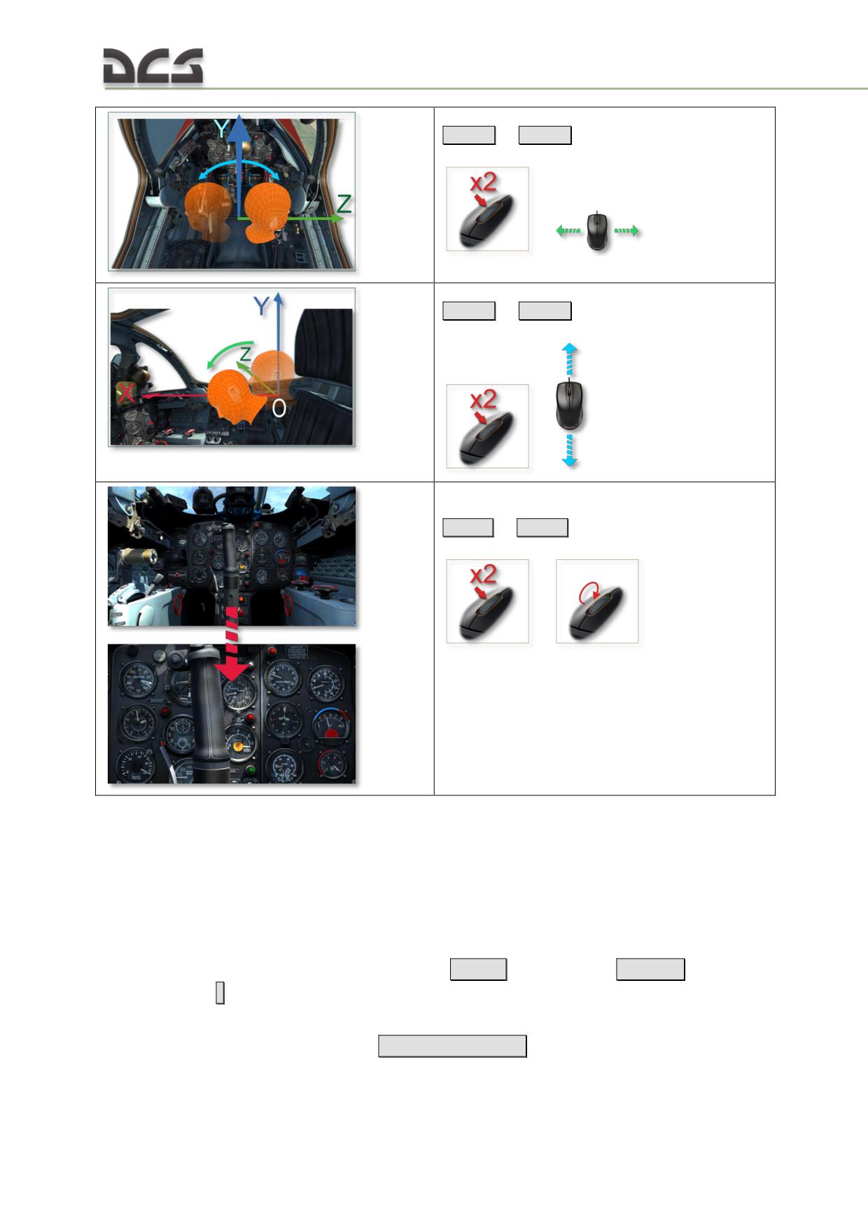
With keyboard:
[Num4]
or
[Num6]
With mouse:
,
With keyboard:
[Num2]
or
[Num8]
With mouse:
,
ZOOM
With keyboard:
[Num*]
or
[Num/]
With mouse:
,
14.4.2. Controlling views in the 6DOF cockpit
Many cockpit objects are located inconveniently (in niches, covered by other
objects). To be able to quickly look at the correct object in flight and return to the
instrument panel, the built-in SnapView function can be used using key
combinations. This function "remembers" custom views created by the player and
allocates corresponding key combinations on the numeric keyboard. After recording,
they can be used with the key combination
[Num0
(modifier) +
Num1..9
(one of 9
needed views)
]
Before creating individual custom views, the player is encouraged to review the pre-
defined default views by pressing
[Num0+Num1..9] in succession. In many cases,
the default views are sufficient for the player’s needs.
404
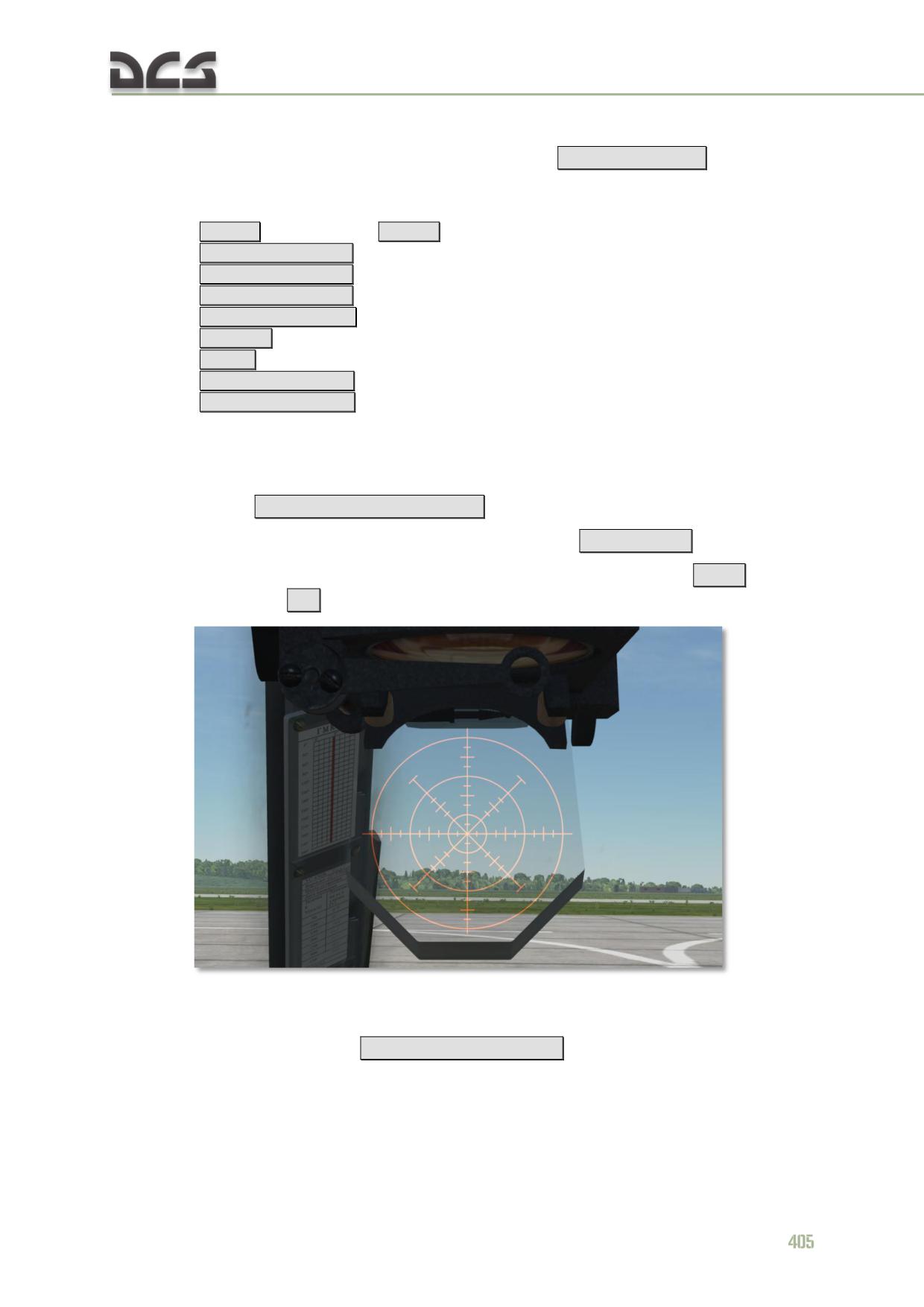
To create a custom SnapView, it is necessary to:
a) activate saving of one of the views by pressing
[Num0+Num1..9]
(only one
number), start of the saving is activated;
NOTE. View adjustments can be done with standard keyboard commands for controlling the camera:
[Num * ] - zoom in slow,
[Num / ]
- zoom out slow,
[Rshift+RCtrl+Num2]
- cockpit camera move DOWN,
[Rshift+RCtrl+Num8]
- cockpit camera move up,
[Rshift+RCtrl+Num4]
- cockpit camera move left,
[Rshift+RCtrl+ Num6]
- cockpit camera move right,
[Num1..9]
- rotation of the current point of view,
[Num5]- center view,
[Rshift+RCtrl+ Num*]
- cockpit camera move forward,
[Rshift+RCtrl+ Num/]
- cockpit camera move back.
b) set up the view as needed (for example - PKV Sight a custom SnapView), for
this is necessary to perform the following steps:
(1) move the camera to the center of the selected object
[Rshift+RCtrl+Num2,8,6,4]
;
(2) turn the sight axis to the desired angle
[Num2,8,6,4]
;
(3) zoom to the object at the desired distance: zoom in
[ * ] or zoom
out
[ / ]
, for result as Fig. 14.2:
Fig. 14.2. The custom SnapView of PKV Sight
(4) finish storing the adjusted views to a file by pressing the key
combination
[Ralt + Num0+Num1..9]
Information about custom views is stored in the file
"C:\Users\<USERNAME>\Saved Games\DCS\Config\View\SnapViews.lua".
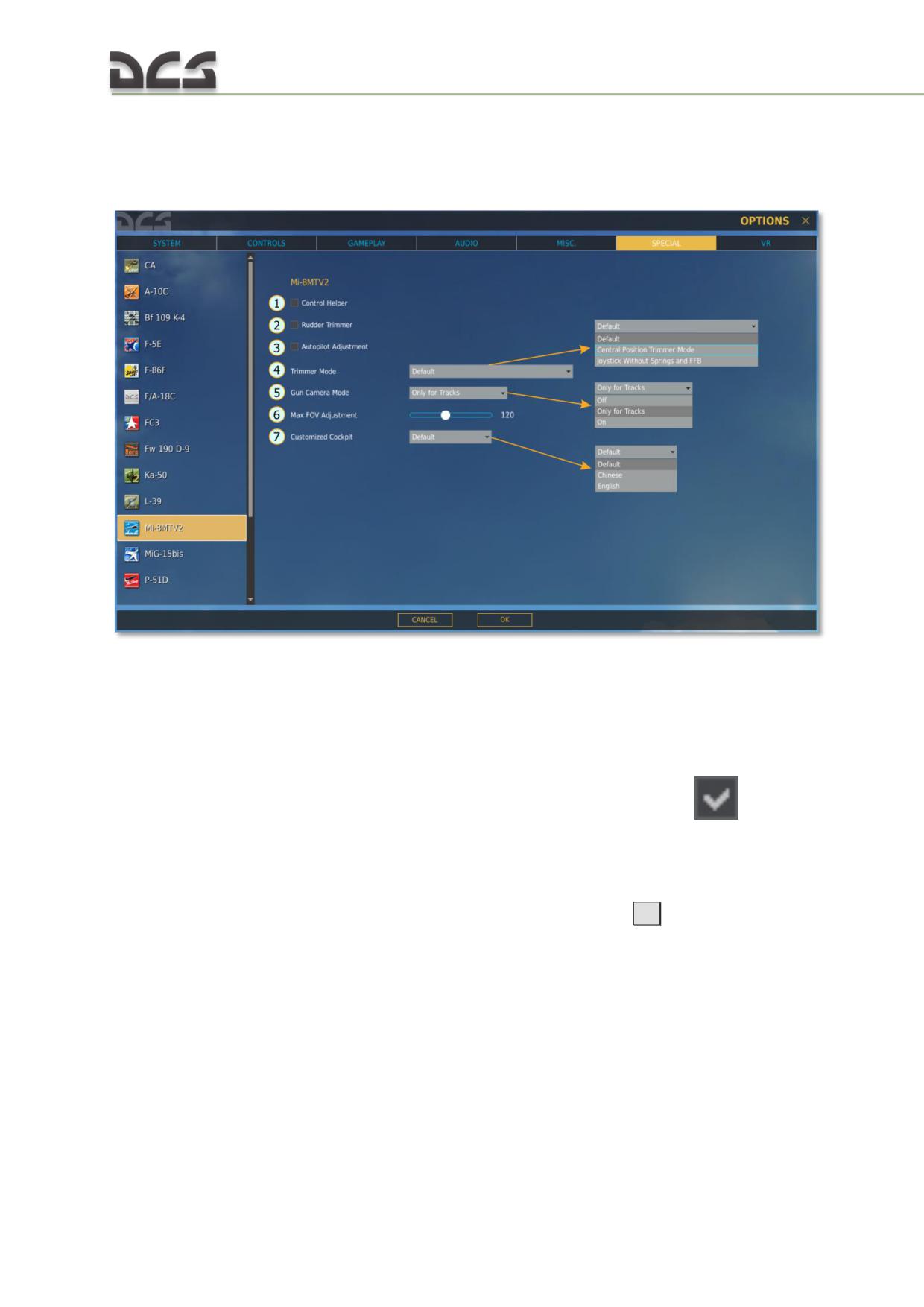
14.5. Special settings of the module
Special settings of the module are located on the SPECIAL tab, Fig. 14.3:
Fig. 14.3. Special settings of the DCS: Mi-8MTV2
1. CONTROL HELPER (checkbox)
5. GUN CAMERA MODE (droplist)
2. RUDDER TRIMMER (checkbox)
6. MAX FOV ADJUSTMENT (slider)
3. AUTOPILOT ADJUSTMENT (checkbox)
7. CUSTOMIZED COCKPIT, language and
4. TRIMMER MODE (droplist)
texture (droplist)
(1) CONTROL HELPER. Activates control helper, if checkbox is checked (
). In this
case helper will smoothify abrupt and high-amplitude deflections of the cyclic, try to
prevent rapid roll, pitch and yaw changes, compensate reactive moment of the tail
rotor. Can be useful to new beginners.
(2) RUDDER TRIMMER. If checked, then when the trimmer button
[T]
is pressed, pedals
will be trimmed simultaneously with cyclic, i.e. pedals in model will retain their
position, even if player returned them to neutral position (due to springs in pedals).
Works in the same way as for joystick with “Central position trimmer mode” option
selected (see below).
(3) AUTOPILOT ADJUSTMENT. If this checkbox is checked, then AI crew chief constantly
(automatically) “adjust” roll and pitch channels by the centering knobs, if deviations
of the indicators are more than 50% of travel range. Adjustment is performed at a
slow rate (not more than 1 degree/sec), therefore player does not feel anything.
406
N O T E . It is possible to adjust autopilot without having this box checked using the
[Ralt + A]
command. In this case AI crew chief will adjust roll and pitch channels only once and report about
actions taken
(4) TRIMMER MODE. It is a droplist with the following entries:
“Default” - joystick works in a normal way: pressing the trimmer button
[T]
only makes trimmer sound, position of the cyclic is equal to the
joystick’s position.
“Central position trimmer mode” - after pressing the trimmer button, the
cyclic remains in the same position, where it was at this moment, and the
following changes in joystick’s position have no impact on cyclic, until
player return his joystick to the center position (with some margin). After
that deflection of the joystick will be added to the current position of cyclic
(latest trimmed position). To reset cyclic trimmer, player must use the
[LCtrl + T]
command;
“Joystick without springs and FFB ” - is intended to be used with customly
modified joysticks, which have centering springs removed. In this case,
when the trimmer button is pressed, the click of the trimmer is heard and
the actual position of the joystick is equal to the position of the virtual
cyclic in the model.
(5) GUN CAMERA MODE. Droplist with the following entries: OFF, Only for tracks, ON. It
specifies the usage of the AKS-2 gun camera.
(6) MAX FOV ADJUSTMENT. This slider sets the initial field of view, when mission is
loaded. Default value is -120°. The most adequate angular sizes of the cockpit
objects are achieved with FOV equal to 90°..
(7) CUSTOMIZED COCKPIT. It is a droplist with the following entries:
“Default” - language of the cockpit labels is selected based on language
settings of the operating system (Russian or English);
“English” - all labels will be on English language;
“Chinese” - all labels will be on Chinese language.
14.6. Additional properties of the aircraft
in the DCS:MI-8MTV2
The DCS Mission Editor includes a number of special “tuning” options for the Mi-
8MTV2 helicopter (Fig. 14.4). In additional to the standard air group settings of the
ME, the following special properties are available for the Mi-8MTV2:
remove/install external hardpoints and PKV gunsight;
sets the rope length for slingload operations (see, 13.1.2, 7).
remove/install exhaust IR suppression devices;
remaining service life of engines;
remove/install additional armor;
remove/install cargo bay doors;
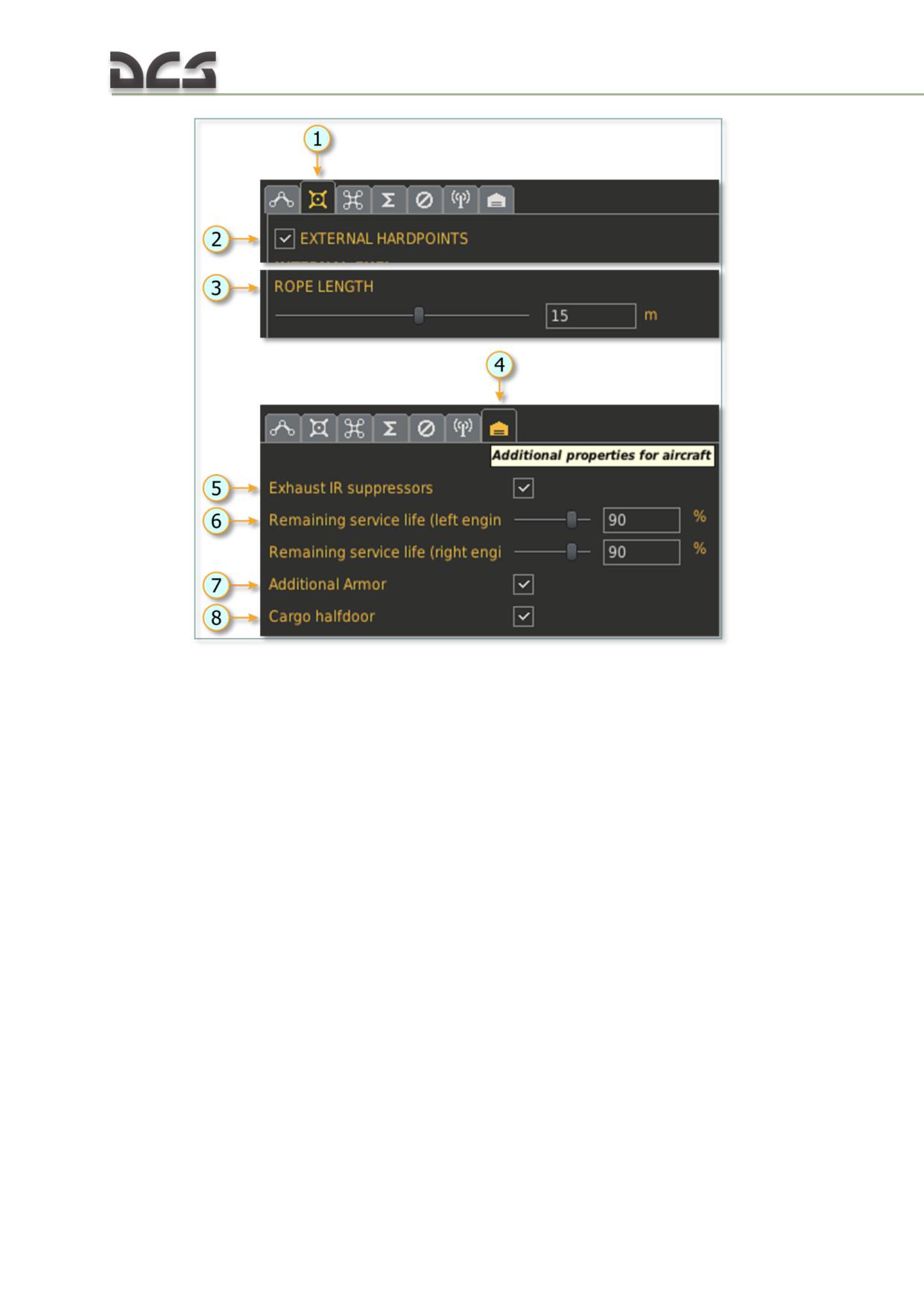
Fig. 14.4. Additional properties of the aircraft in the DCS:MI-8MTV2
1. Activates payload tab
5. Install exhaust IR suppression devices
2. Installs external hardpoints
6. Sets remaining service life of the engines
3. Sets the rope lengh in m. for sling load
7. Installs additional armor
operations
8. Installs cargo bay doors
4. Activates the additional properties of the
aircraft tab
(2) THE EXTERNAL HARDPOINTS checkbox is checked - enables attachment of all
available weapon on external hardpoints and increases weight of empty helicopter by
401 kg.
(3) SET THE LENGTH ROPE for transporting external cargo
(5) INSTALLS EXHAUST IR SUPPRESSION DEVICES (7.12). It decreases engines’ IR signature
by approximately two times. This reduces lock on range for IR SAMs and increases
probability of successful flight through SAM protected areas.
6) ENGINES’ SERVICE LIFE COEFFICIENT allows creating missions, in which helicopter’s
power plant will be worned out, which, in its order, requires additional skills of the
player, when performing designated task.
NOTE: 90% corresponds to new engine from the manufacturing plant.
100% is a testing stand power (conditionally)
This coefficient is non-linear, therefore:
75% - main rotor RPM drops at collective of 11,5°.
408
50% - main rotor RPM drops at collective of 5°. It is not possible to fly using these
engines.
(7) ADDITIONAL ARMOR checkbox - additional armor increases survivability of crew and
important helicopter’s units from bullets and fragments. Increases empty weight of
helicopter by 419 kg.
(8) INSTALLS OR REMOVES CARGO BAY DOORS - removed cargo bay doors increase amount
of different game variations and decrease helicopter’s weight by 130 kg.
14.7. Kneeboard
To ease the learning process and also to compensate "flight in front of the monitor"
inconveniences, kneeboard are available in the game. It contains information about
current states of important parameters of the equipment, AI-gunners state and some
useful key combinations for changing, mentioned above parameters, Fig. 14.5:
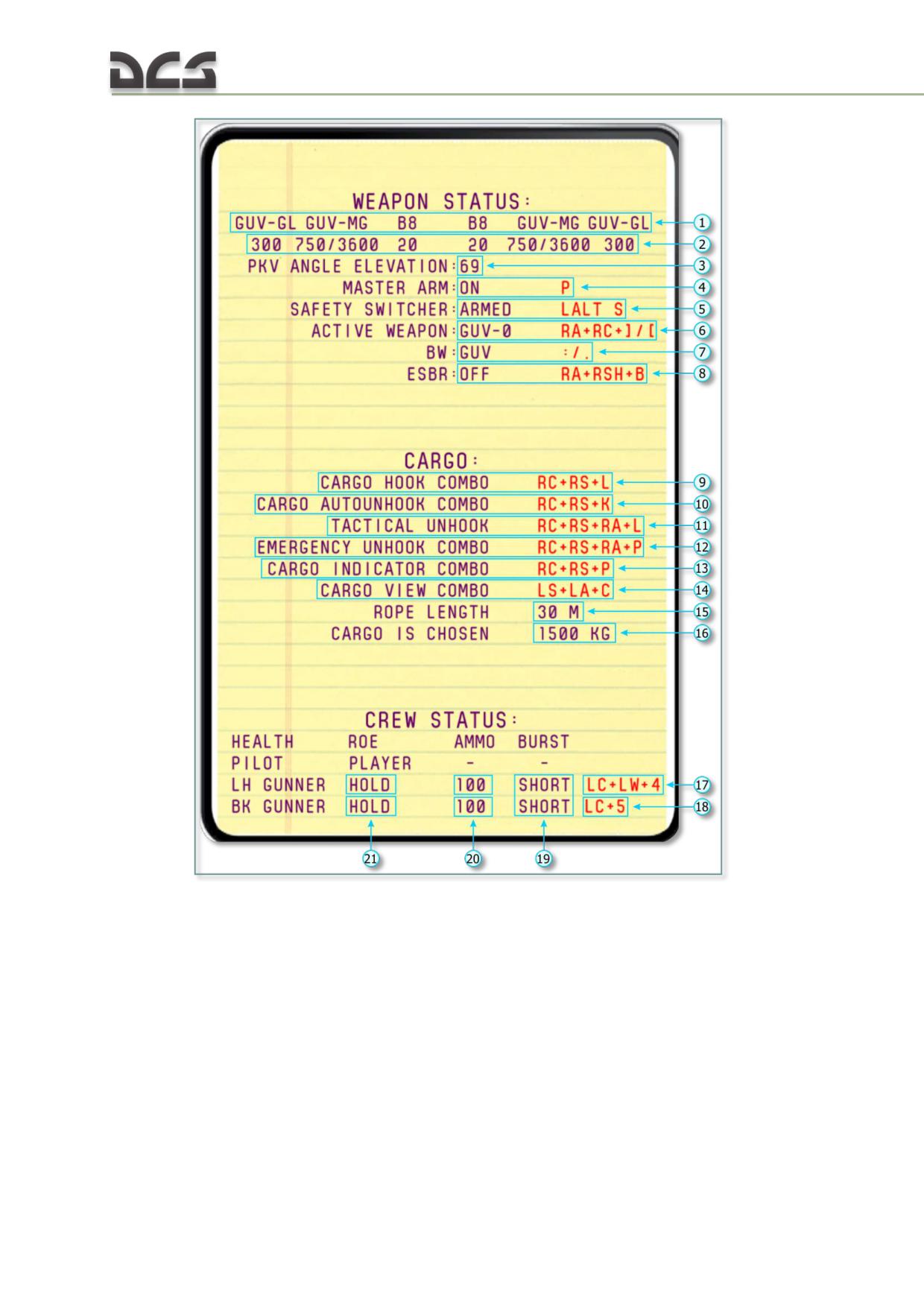
Fig. 14.5. Kneeboard
WEAPON
CARGO OPERATIONS
21. Indication of weapon on hardpoints:
9. Key command for manual cargo hooking.
GUV-GL - GUV grenade launcher
10. Key command, activating autounhook
GUV-MG - GUV machine gun
feature, when cargo is unhooked once it
UPK - UPK-23-250
touches the ground.
B8 - B8V20 rockets
11. Key command for tactical unhook of the
Bo - bombs
cargo in the air
2. Remaining ammo (for GUV-MG in numerator for
12. Key command for emergency unhook of
12.7-mm machine gunes, in denominator for 7.62-
the cargo in the air
mm machine guns)
13. Key command activating cargo indicator
3. PKV elevation angle
14. Key command activating view on cargo
4. Position of master arm (ГВ) on the left circuit
from the blister/ return back to normal view
breaker console and key command for enabling or
15. Rope length, selected in ME.
410
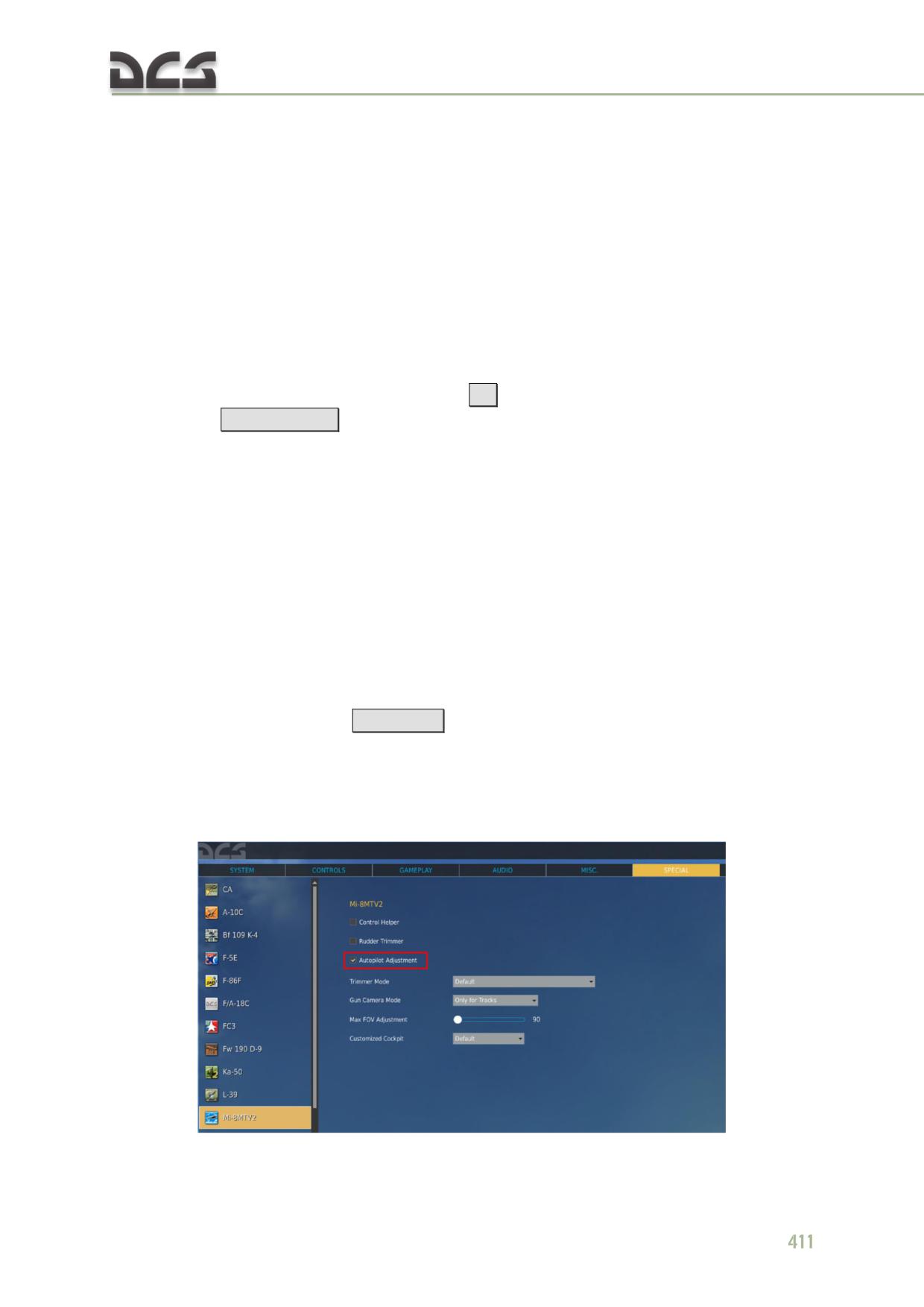
disabling master arm.
16. Weight of chosen or hooked cargo
5. Safety switcher position(ARMED, SAFE) and a
key command for toggling it.
CREW STATUS
6. Active weapon selection (RS - rockets, UPK,
17. Key command, changing ROE setting for
PKT, GUV ) and key combinations for changing
the door gunner (HOLD, RET.FIRE, FIRE)
active weapon (RC=RCtrl, RA=Ralt, R=Rshift)
18. Key command, changing ROE setting for
7. Position of the rotation switch on the copilot's
the tail gunner (HOLD, RET.FIRE, FIRE)
weapons control panel (I, II, III, IV, V, GUV) and
19. Burst length of AI-gunners (can not be
corresponding key commands.
changed)
8. Position of the ESBR-3P electrical release control
20. Remaining ammo, in percents of total
box (ON, OFF) and key commands.
ammo.
21. Indication of ROE settings for the AI-
gunners
The kneeboard is activated by pressing
[K]
(shown only while the key is kept
pressed) or
[Rshift + K]
(toggle mode, i.e. switched on/off by the same key
combination).
14.8. Use of AI crew members assistance
In the game, AI can perofrm several functions:
autopilot adjustment by the AI crew chief;
voice assistance by the AI crew chief (automatic voice assistant) while
playing with sling loads, which helps positioning the helicopter precisely
over the cargo for hooking it, or over drop zone, for unhooking it.
14.8.1. Autopilot adjustment by the AI crew chief
It can be done by the player request or automatically.
Command from the player is
[Ralt + A]
. After activation, the AI crew chief smoothly
adjust roll and pitch channels, using corresponding centering knobs, all actions he
performs are commented by voice.
For automatic adjustment, one must check the corresponding checkbox in the special
tab of the module settings:
14.8.2. Commands, given by the AI crew chief,
while playing with sling loads
This commands are given by the AI crew chief during hovering over the cargo for
unhooking it, during lifting off the cargo and unhooking the cargo. Refer to Table
13.1 and chapter 13.1.1 for detailed explanation of this feature.
412
DIGITAL COMBAT SIMULATOR Mi-8МТV2
15.
ABBREVIATIONS & TERMS
%Q
Percent Torque
AC
Alternating Current
ACB
Automatic Circuit Breaker
ADF
Automatic Direction Finder
AGL
Above Ground Level
Ah
Amper x hour
AI
Artificial intelligence
ALT
Alternator
ALT
Altitude/Altimeter
ALTM
Altimeter
AM
Amplitude Modulation
AMP
Ampere
ANT
Antenna
APU
Auxiliary power unit
ATTD
Attitude
AUTO
Automatic
AUX
Auxiliary
AVGAS
Aviation Gasoline
BAT
Battery
BDHI
Bearing Distance Heading Indicator
BFO
Beat Frequency Oscillator
BL
Butt Line
BRIL
Brilliance
BRT
Bright
C
Celsius
CARR
Carrier
CAS
Calibrated Airspeed
CCW
Counter Clockwise
CDI
Course Deviation Indicator
CG
Center of Gravity
CL
Centerline
CMPS
Compass
CNVTR
Converter
COLL
Collision
COMM
Communication
COMPT
Compartment
CONT
Continuous
CONT
Control
CONV
Converter
CW
Clockwise
DC
Direct Current
DCP
Dispenser Control Panel
DECR
Decrease
deg
degree
DET
Detector
DF
Direction Finding
DG
Directional Gyro
DIS
Disable
DISS
DISP
Dispense
DPD
Dust protection devices (the same as PSS)
DSCRM
Discriminator
ECL
Engine Condition Levers ("РРУД" in RU)
ECM
Electronic Countermeasures
EGS
Exhaust Gas Suppressor
EGT
Exhaust Gas Temperature
ELEC
Electrical
EMER
Emergency
END
Endurance
ENG
Engine
ESS
Essential
EXH
Exhaust
EXT
Extend
EXT
Exterior
F
Fahrenheit
FAT
Free Air Temperature
FCU
Fuel Control Unit
FITG
Fitting
FM
Frequency Modulation
FOD
Foreign Object Damage
fpm
feet per minutes
FPS
Feet Per Second, or Frame Per Second
FREQ
Frequency
FS
Fuselage Station
FT
Foot
ft
feet
FT/MIN
Feet Per Minute
ft-in
feet&inch
FUS
Fuselage
FWD
Forward
G
Guard
G
Gravity
GAL
Gallon
gal
Gallon
GD
Guard
GEN
Generator
GND
Ground
GOV
Governor
GPU
Ground Power Unit
GRWT
Gross Weight
GW
Gross Weight
HDG
Heading
HF
High Frequency
HIT
Health Indicator Test
HTR
Heater
HVAR
High Velocity Aircraft Rocket
HYD
Hydraulic
Hz
Herz
IAS
Indicated Airspeed
ICS
Interphone Control Station
IDENT
Identification
IFF
Identification Friend or Foe
IGE
In Ground Effect
in
Inch
INCR
Increase
IND
Indication/Indicator
INHG
Inches of Mercury
INOP
Inoperative
INST
Instrument
INT
Internal
INT
Interphone
INV
Inverter
INVTR
Inverter
IR
Infrared
IRT
Indicator Receiver Transmitter
ISA
International Standard Atmosphere
KCAS
Knots Calibrated Airspeed
kHz
Kilohertz
KIAS
Knots Indicated Airspeed
km
Kilometer
kN
Kilonewton
knots
Nautical Miles per hour
knots
Nautical Miles per hour
kp
Kilogram-force
KTAS
Knots True Airspeed
kts
Knots
kVA
Kilovolt-Ampere
kW
Kilowatt
L
Left
LABS
Low-altitude bombing system
LB
Pounds
lbf
pound-force
lbs
Pounds
LCM
Left (button) Click Mouse
LDG
Landing
LH
Left Hand
LSB
Lower Sideband
LT
Lights
416
LTG
Lighting
LTS
Lights
MAG
Magnetic
MAN
Manual
MAX
Maximum
MED
Medium
MHF
Medium-High Frequency
MHz
Megahertz
MIC
Microphone
mil
417illiard, 1\6400 part of a circle
MIN
Minimum
MIN
Minute
MISC
Miscellaneous
mm
Millimeter
MON
Monitor
MPC
Manual pip control
MWO
Modification Work Order
N1
Gas Turbine Speed (Compressor)
N2
Power Turbine Speed (link with Main Rotor)
NAV
Navigation
NET
Network
NM
Nautical Mile
nm
Nautical Mile
NO
Number
NON-ESS
Non-Essential
NON-SEC
Non-Secure
NORM
Normal
NR, Nr
Main Rotor RPM
NVG
Night Vision Goggles
OGE
Out of Ground Effect
PED
Pedestal
PKT
7.62 Mashin Gun
PLT
Pilot
PRESS
Pressure
PRGM
Program
PSI
Pounds Per Square Inch
PSS
Particle Separator System (the same as DPD)
PTIT
Power Turbine Inlet Temperature
PVT
Private
PWR
Power
QTY
Quantity
R
Right
R/C
Rate of Climb
R/D
Rate of Descent
RCM
Right (button) Click Mouse
RCVR
Receiver
RDR
Radar
RDS
Rounds
REL
Release
REM
Remote
RETR
Retract
RETRAN
Retransmission
RF
Radio Frequency
RH
Right Hand
RI
Remote Height Indicator
RKT
Rockets
RPM
Revolutions Per Minute
SAM
Surface to Air Missile
SEC
Secondary
SEC
Secure
SEL
Select
SENS
Sensitivity
SL
Searchlight
SOL
Solenoid
SQ
Squelch
SQFT
Square Feet
SSB
Single Sideband
STA
Station
STBY
Standby
T/R
Transmit-Receive
TAS
True Airspeed
TEMP
Temperature
TGT
Turbine Gas Temperature
TRANS
Transfer
TRANS
Transformer
TRANS
Transmitter
TRQ
Torque
UHF
Ultra-High Frequency
Gun pods equipped with GSh-23L (ГШ-23Л) twin-
UPK
barrel 23 mm cannon
USB
Upper Sideband
V
Volt
VAC
Volts, Alternating Current
VDC
Volts, Direct Current
VHF
Very high Frequency
VM
Volt Meter
VNE
Velocity, Never Exceed (Airspeed
VOL
Volume
VOR
VHF Omni Directional Range
WL
Water line
WPN
Weapon
XCVR
Transceiver
XMIT
Transmit
XMSN
Transmission
418
XMTR
Transmitter
ΔF
Increment of Equivalent Flat Plate Drag Area
RU
АВСК
Аппаратура внутренней связи и коммутации
АЗС
Автомат защиты сети
АНО
Аэронавигационные огни
АРК
Автоматический радиокомпас
АРП
Автоматический радиопеленгатор
АЦП
Аналогово-цифровой преобразователь
АЭР
Аэродром
БАНО
Бортовые аэронавигационные огни. Красный - левый, зеленый - правый.
БЧ
Боевая часть
БПРМ
Ближняя приводная радиостанция с маркером
БПРС
Ближняя приводная радиостанция (1000 м от торца ВПП)
ВМГ
Винтомоторная группа
ВПП
Взлетно-посадочная полоса
ВС
Воздушное судно
ВСУ
Вспомогательная силовая установка
ГВ
Главный выключатель
ГПК
Гирополукомпас
ГУВ
Гондола универсальная вертолетная
ДИСС
Доплеровский измеритель составляющих скоростей
ДПРМ
Дальняя приводная радиостанция с маркером
ДПРС
Дальняя приводная радиостанция (4000 м от торца ВПП)
ЗПУ
Заданный путевой угол
ИВС
Истинная воздушная скорость
ИПМ
Исходный пункт маршрута
КМГУ
Контейнер мелких грузов универсальный
КПМ
Конечный пункт маршрута
КУР
Курсовой угол радиостанции
КУЦ
Курсовой угол цели
ЛА
Летательный аппарат
ЛБУ
Линейное боковое уклонение
ЛУР
Линейное упреждение разворота
МВ
Минное вооружение
МК
Магнитный курс
МПР
Магнитный пеленг радиостанции
МСА
Международная стандартная атмосфера
НАР Неуправляемая авиационная ракета
НВ
Несущий винт
НОП Наземный обслуживающий персонал
НППУ Несъемная подвижная пушечная установка
НВР Неуправляемое ракетное воорежение
ОПРС Отдельная приводная радиостанция (NDB)
ОПС Оптическая прицельная система
ОСП Оборудование системы посадки. Система посадки по дальней и ближней приводным
радиостанциям (ICAO 2NDB Approach)
ОТ
Оперативная точка
ОШ
Общий шаг винтов
ПВД Приемник воздушного давления
ПВО Противовоздушная оборона
ПВР Пульт выбора режимов
ПЗУ Пылезащитное устройство
ПНК Пилотажно-навигационный комплекс
ПНП Планово-навигационный прибор
ПОС Противообледенительная система
ППД Приемник полного давления
ППМ Промежуточный пункт маршрута
ППУ Продольно-поперечное управление (ручка)
ПрПНК Прицельно-пилотажно-навигационный комплекс
ПРС Приводная радиостанция
ПТБ Подвесной топливный бак
ПУ
Путевой угол
ПУИ Пульт управления и индикации
ПУР Пульт управления режимами
РОШ Рычаг общего шага
РППУ Ручка продольно-поперечного управления
РРУ (РРУД) Рычаги раздельного управления (двигателями)
РС
Реактивные снаряды
РСНВ Режим самовращения несущего винта
РУ
Расчетный угол
САР Система автоматического регулирования
СГФ Строительная горизонталь фюзеляжа
СПО Стрелково-пушечное оружие
СПУ Вертолетное переговорное устройство
СРО Вертолетный радиолокационный ответчик госопознавания
СТ
Свободная турбина
СУО Система управления оружием
420
ТК
Турбокомпрессор
ТТХ
Тактико-технические характеFigтики
УВД Управление воздушным движением
ФПУ Фактический путевой угол
ХС
Хвостовой сигнал. Белого цвета, установлен на киле
ЦАП Цифро-аналоговый преобразователь
ЦСО Центральный сигнальный огонь
ШБЖ Штурманский бортовой журнал
ЭВУ
Экранно-выхлопное устройство
ЭРД Электронный регулятор двигателя
GPS
Global Positioning System - среднеорбитальная спутниковая радионавигационная система
НАВСТАР, разработанная в США
NDB Nondirectional radio-beacon (отдельная приводная радиостанция ОПРС)
NAVSTAR
- NAVigation Satellites for Timing And Ranging (навигационные спутники для
определения времени и расстояний) - название системы GPS в англоговорящих странах, отсюда
русское НАВСТАР
VOR Very-high-frequency omnidirectional range (всенаправленный курсовой радиомаяк УKB-
диапазона)
DIGITAL COMBAT SIMULATOR Mi-8МТV2
16.
THE METRIC SYSTEM AND EQUIVALENTS, CONVERSION
FACTORS
16.1. The Metric System and Equivalents
Linear Measure
Liquid Measure
1 centimeter = 10 millimeters = .39 inch
1 centiliter = 10 milliters = .34 fl. ounce
1 decimeter = 10 centimeters = 3.94 inches
1 deciliter = 10 centiliters = 3.38 fl. ounces
1 meter = 10 decimeters = 39.37 inches
1 liter = 10 deciliters = 33.81 fl. ounces
1 dekameter = 10 meters = 32.8 feet
1 dekaliter = 10 liters = 2.64 gallons
1 hectometer = 10 dekameters = 328.08 feet
1 hectoliter = 10 dekaliters = 26.42 gallons
1 kilometer = 10 hectometers = 3,280.8 feet
1 kiloliter = 10 hectoliters = 264.18 gallons
Weights
Square Measure
1 centigram = 10 milligrams = .15 grain
1 sq. centimeter = 100 sq. millimeters = .155
1 decigram = 10 centigrams = 1.54 grains
sq. inch
1 gram = 10 decigram = .035 ounce
1 sq. decimeter = 100 sq. centimeters = 15.5
1 decagram = 10 grams = .35 ounce
sq. inches
1 hectogram = 10 decagrams = 3.52 ounces
1 sq. meter (centare) = 100 sq. decimeters =
1 kilogram = 10 hectograms = 2.2 pounds
10.76 sq. feet
1 quintal = 100 kilograms = 220.46 pounds
1 sq. dekameter (are) = 100 sq. meters =
1 metric ton = 10 quintals = 1.1 short tons
1,076.4 sq. feet
1 sq. hectometer (hectare) = 100 sq.
dekameters = 2.47 acres
1 sq. kilometer = 100 sq. hectometers = .386
sq. mile
Cubic Measure
1 cu. centimeter = 1000 cu. millimeters = .06
cu. inch
1 cu. decimeter = 1000 cu. centimeters =
61.02 cu. inches
1 cu. meter = 1000 cu. decimeters = 35.31
cu. feet

DIGITAL COMBAT SIMULATOR Mi-8МТV2
16.2. Approximate Conversion Factors
To change (imperial)
To (metric)
Multiply by
inches
centimeters
2.540
feet
meters
.305
yards
meters
.914
miles
kilometers
1.609
knots
kph
1.852
square inches
square centimeters
6.451
square feet
square meters
.093
square yards
square meters
.836
square miles
square kilometers
2.590
acres
square hectometers
.405
cubic feet
cubic meters
.028
cubic yards
cubic meters
.765
fluid ounces
milliliters
29,573
pints
liters
.473
quarts
liters
.946
gallons
liters
3.785
ounces
grams
28.349
pounds
kilograms
.454
short tons
metric tons
.907
pound-feet
Newton-meters
1.356
pound-inches
Newton-meters
.11296
ounce-inches
Newton-meters
.007062
(metric)
(imperial)
centimeters
inches
.394
meters
feet
3.280
meters
yards
1.094
kilometers
miles
.621
kph
knots
0.54
square centimeters
square inches
.155
square meters
square feet
10.764
square meters
square yards
1.196
square kilometers
square miles
.386
square hectometers
acres
2.471
cubic meters
cubic feet
35.315
cubic meters
cubic yards
1.308
milliliters
fluid ounces
.034
liters
pints
2.113
liters
quarts
1.057
liters
gallons
.264
grams
ounces
.035
kilograms
pounds
2.205
metric tons
short tons
1.102
DIGITAL COMBAT SIMULATOR Mi-8МТV2
17.
DEVELOPERS
BELSIMTEK
Management
Project manager, games and
Alexander "PilotMi8" Podvoyskiy technical documentation, alpha
testing.
Documentation
Games documentation: Mi-8 history,
Vladimir Timofeev
aerodynamics, Cockpit systems and
controls.
Gene "EvilBivol-1" Bivol
QS manual
Programmers
Andrey Kovalenko, Nikolay Volodin, Vladimir Mikhailov, Boris Silakov, Alexander
Miskovich, Eugeniy Gribovich, Maxim Zelensky, Dmitry Moskalenko, Vitaly Perepelkin
Sounds
Konstantin "btd" Kuznetsov
Music and sound effects
Designers
Pavel "DGambo" Sidorov
Lead designer cockpit, damage model
Andrey Reshetko
Pilots and gunners
Stanislav Kolesnikov
Cockpit
Valery "Palmal" Miagkiy
Options of coloration (livery) of helicopters
Tester staff
Alexander "AlexanderT" Titarenko
Dmitry "Laivynas" Koshelev
Gene "EvilBivol-1" Bivol
"AlhpaOneSix "
"BillyCrusher"
"Derelor"
"FrogFoot"
"Kairat"
"Rik"
"Shadowowweosa"
"Vibora"
"Wadim"
Mission and campaign
Oleg Dzen Fedorenko, Dmitry Koshelev
Voices recording for campaign
Russian version:
dr.lex, BTD, Laivynas, Vatel, Dzen, MadShark, wildcat191, Maler, Rustam
English version:
graywo1fg, Weta43, EvilBivol-1, paulrkiii, Joyride, Walter, Curtis, Alex, Jeremy,
Headspace, SimFreak, SiThSpAwN
Training missions
Eugeny "EvilBivol-1" Bivol,
Vyacheslav "SL PAK" Paketny
Special thanks
Kairat "Kairat" Jaksbaev For
organizing
audio
recording,
video,
(1st class pilot)
photographs, to help test the dynamics of the
model and refinement of work systems in a real
helicopter
Oleg Vasilenko (pilot- For photos and videos, to help test the dynamics of
sniper, test pilot)
the model and refinement of work systems in a
real helicopter
Alexander
Titorenko
For assistance in refining and adding systems,
(pilot of the Mi-8, civil
improving the gameplay of the game with Sling
aviation)
load.
"devrim”
For the materials of the textures for the English
cockpit
Nikolay
"kolyakar" For adding new liveries for the DCS: Mi-8MTV2
Karahtincev
Vitaly "Vert-117"
For invaluable assistance in tuning of systems
Werner
"derelor" For professionalism and thoroughness in editing
Siedenburg
this manual
Ralf “upuaut”
For development of new cargos and FARPs for the
DCS: Mi-8MTV2
Aleksey “tester”
For help in selection of information for this Flight
manual
Vitaly "LazzySeal" Kachan For editing of English version different texts,
translation and voice-over of subtitles for Sling load
operations
428
18
BIBLIOGRAPHY AND SOURCES
DIGITAL COMBAT SIMULATOR Mi-8МТV2
18.
BIBLIOGRAPHY AND SOURCES
1. Вертолет Ми-8МТ. Техническое описание, 1982.
2. Вертолет Ми-8МТВ. Руководство по эксплуатации и техническому
обслуживанию. Книга V. Радиоэлектронное оборудование.
3. Гессоу А., Мейерс Г. Аэродинамика вертолета. Перевод Бирюлина В.
Под редакцией Братухина И.
- М.: Государственное издательство
оборонной промышленности. 1954.
4. Дмитриев В., Вождаев Е., Каргопольцев Е., Приоритетные
направления повышения
конкурентоспособности
вертолетной
техники. - ЦАГИ. 2002.
5. Загордан А. Элементарная теория вертолета.
- М.: Военное
Издательство Министерства Обороны Союза ССР. 1955.
6. Инструкция экипажу вертолета Ми-8МТ. Второе издание, 1982.
7. Ковалев В. Устройство вертолета.
8. РЛЭ Ми-8МТВ5
9. РТЭ двигателя АИ-9в
10. РТЭ двигателя ТВ3-117ВМ
11. РТЭ Ми-8МТВ5
12. Техническое описание АРК-9.
13. Техническое описание АРК-УД.
14. Техническое описание ДИСС-15.
15. Техническое описание П-503Б.
16. Техническое описание Р-828.
17. Техническое описание Р-863.
18. Техническое описание РИ-65Б.
19. Техническое описание СПУ-7.
20. Техническое описание ЯДРО-1А.