ROTORCRAFT FLYING HANDBOOK (2000) - page 2
3.
Confusing attitude changes for altitude changes,
more pedal pressure as the helicopter turns to the cross-
which result in improper use of the controls.
wind position. This is because the wind is striking the
tail surface and tail rotor area, making it more difficult
4.
Hovering too high, creating a hazardous flight
for the tail to turn into the wind. As pedal pressures
condition.
increase due to crosswind forces, you must increase the
cyclic pressure into the wind to maintain position. Use
5.
Hovering too low, resulting in occasional touch-
the collective with the throttle to maintain a constant
down.
altitude and r.p.m. [Figure 9-2]
HOVERING TURN
After the 90° portion of the turn, you need to decrease
A hovering turn is a maneuver performed at hovering
pedal pressure slightly to maintain the same rate of
altitude in which the nose of the helicopter is rotated
turn. Approaching the 180°, or downwind, portion,
either left or right while maintaining position over a
you need to anticipate opposite pedal pressure due to
reference point on the surface. The maneuver requires
the tail moving from an upwind position to a down-
the coordination of all flight controls and demands pre-
wind position. At this point, the rate of turn has a ten-
cise control near the surface. You should maintain a
dency to increase at a rapid rate due to the
constant altitude, rate of turn, and r.p.m.
weathervaning tendency of the tail surfaces. Because
of the tailwind condition, you need to hold rearward
TECHNIQUE
cyclic pressure to keep the helicopter over the same
Initiate the turn in either direction by applying anti-
spot.
torque pedal pressure toward the desired direction. It
should be noted that during a turn to the left, you need
Because of the helicopter’s tendency to weathervane,
to add more power because left pedal pressure
maintaining the same rate of turn from the 180° posi-
increases the pitch angle of the tail rotor, which, in turn,
tion actually requires some pedal pressure opposite the
requires additional power from the engine. A turn to the
direction of turn. If you do not apply opposite pedal
right requires less power. (On helicopters with a clock-
pressure, the helicopter tends to turn at a faster rate.
wise rotating main rotor, right pedal increases the pitch
The amount of pedal pressure and cyclic deflection
angle and, therefore, requires more power.)
throughout the turn depends on the wind velocity. As
you finish the turn on the upwind heading, apply
As the turn begins, use the cyclic as necessary (usually
opposite pedal pressure to stop the turn. Gradually
into the wind) to keep the helicopter over the desired
apply forward cyclic pressure to keep the helicopter
spot. To continue the turn, you need to add more and
from drifting.
WIND
Cyclic - Forward
Cyclic - Right
Cyclic - Rearward
Cyclic - Left
Cyclic - Forward
Pedal - Some left in
Pedal - Most left
Pedal - Changing from
Pedal - Most right pedal
Pedal - Some right to
hover, more left to start
pressure in turn.
left to right pressure.
pressure in turn.
stop turn, then left to
turn to left.
maintain heading.
Collective -Most power
Collective - Power
Collective - Least power
Collective - Power
in turn.
reducing.
in turn.
Collective - Increasing
required to hover at
as left pedal applied.
desired height.
Throttle - As necessary
Throttle - As necessary
Throttle - As necessary
to maintain r.p.m.
to maintain r.p.m.
to maintain r.p.m.
Throttle - As necessary
Throttle - As necessary
to maintain r.p.m.
to maintain r.p.m.
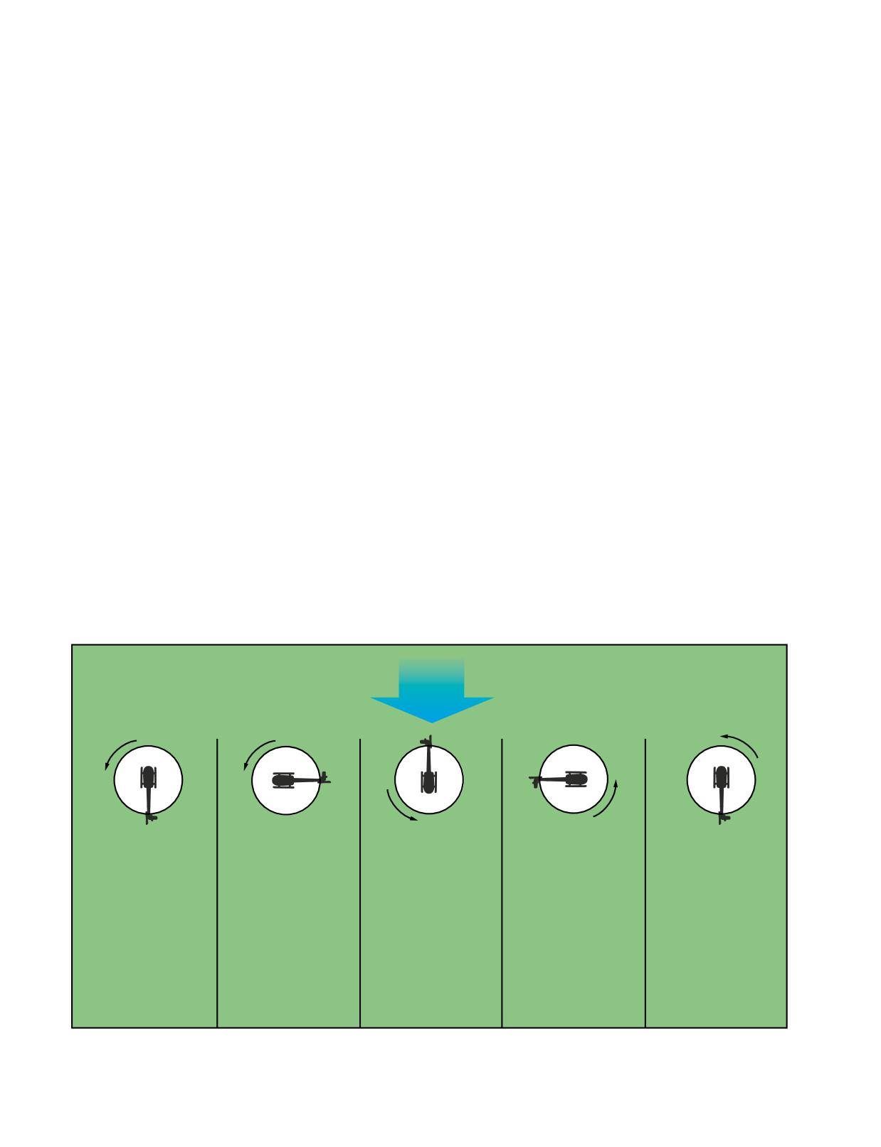
Figure 9-2. Left turns in helicopters with a counterclockwise rotating main rotor are more difficult to execute because the tail
rotor demands more power. This requires that you compensate with additional collective pitch and increased throttle. You
might want to refer to this graphic throughout the remainder of the discussion on a hovering turn to the left.
9-6
Control pressures and direction of application change
continuously throughout the turn. The most dramatic
change is the pedal pressure (and corresponding power
requirement) necessary to control the rate of turn as the
helicopter moves through the downwind portion of the
maneuver.
Turns can be made in either direction; however, in a
high wind condition, the tail rotor may not be able to
produce enough thrust, which means you will not be
able to control a turn to the right in a counterclockwise
Reference
rotor system. Therefore, if control is ever question-
Points
able, you should first attempt to make a 90° turn to the
left. If sufficient tail rotor thrust exists to turn the
helicopter crosswind in a left turn, a right turn can
be successfully controlled. The opposite applies to
helicopters with clockwise rotor systems. In this
case, you should start your turn to the right.
Hovering turns should be avoided in winds strong
enough to preclude sufficient aft cyclic control to
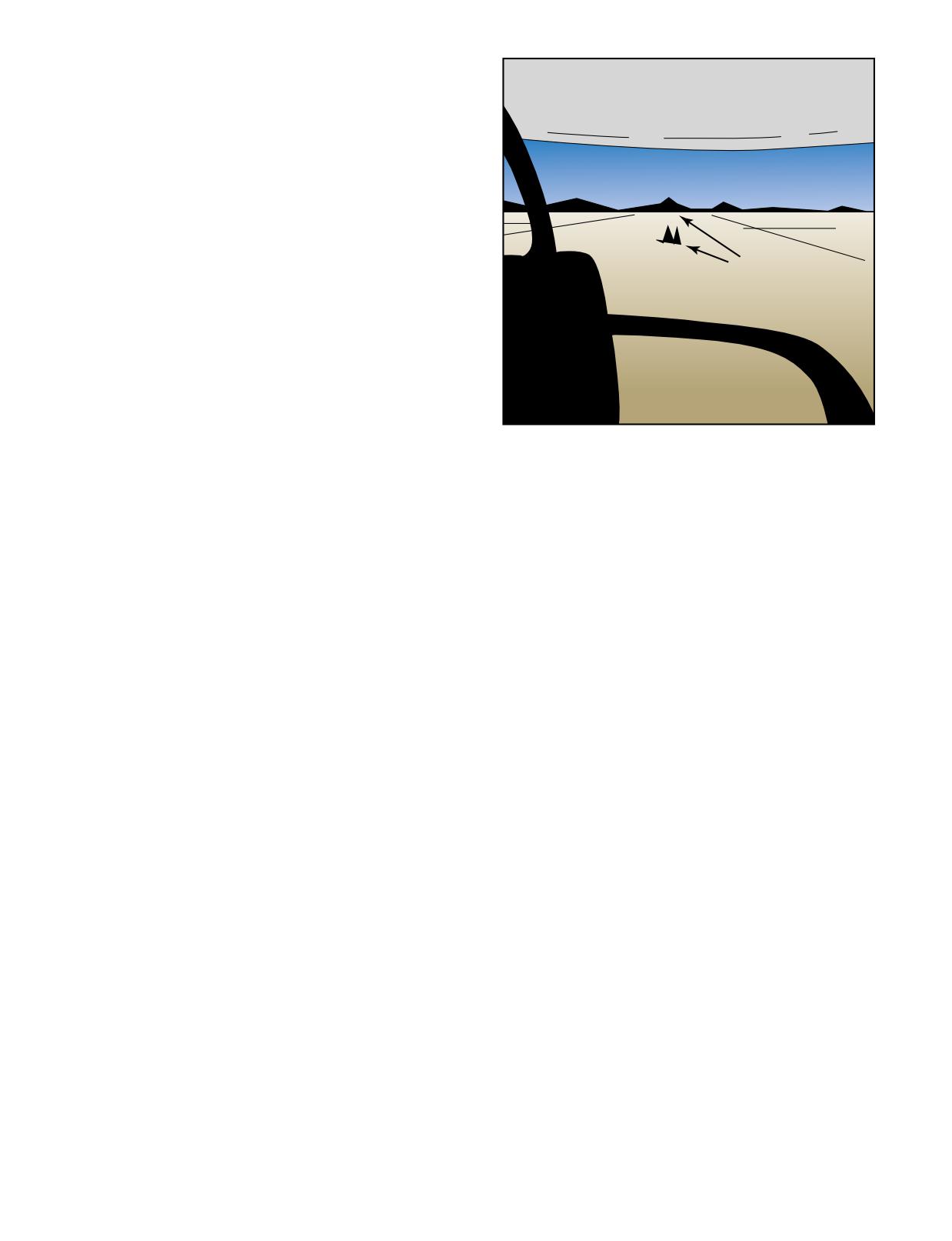
Figure 9-3. To maintain a straight ground track, use two refer-
maintain the helicopter on the selected surface
ence points in line and at some distance in front of the helicopter.
reference point when headed downwind. Check
the flight manual for the manufacturer’s recom-
mendations for this limitation.
pedals, altitude with the collective, and the proper
r.p.m. with the throttle.
COMMON ERRORS
1.
Failing to maintain a slow, constant rate of turn.
To stop the forward movement, apply reward cyclic
2.
Failing to maintain position over the reference
pressure until the helicopter stops. As forward motion
point.
stops, return the cyclic to the neutral position to pre-
vent rearward movement. Forward movement can also
3.
Failing to maintain r.p.m. within normal range.
be stopped by simply applying rearward pressure to
level the helicopter and let it drift to a stop.
4.
Failing to maintain constant altitude.
COMMON ERRORS
5.
Failing to use the antitorque pedals properly.
1.
Exaggerated movement of the cyclic, resulting in
erratic movement over the surface.
HOVERING-FORWARD FLIGHT
2.
Failure to use the antitorque pedals properly,
You normally use forward hovering flight to move a
resulting is excessive heading changes.
helicopter to a specific location, and it is usually begun
from a stationary hover. During the maneuver, constant
3.
Failure to maintain desired hovering altitude.
groundspeed, altitude, and heading should be maintained.
4.
Failure to maintain proper r.p.m.
TECHNIQUE
HOVERING-SIDEWARD FLIGHT
Before starting, pick out two references directly in
Sideward hovering flight may be necessary to move
front and in line with the helicopter. These reference
the helicopter to a specific area when conditions make
points should be kept in line throughout the maneuver.
it impossible to use forward flight. During the maneu-
[Figure 9-3]
ver, a constant groundspeed, altitude, and heading
should be maintained.
Begin the maneuver from a normal hovering altitude by
applying forward pressure on the cyclic. As movement
begins, return the cyclic toward the neutral position to
TECHNIQUE
keep the groundspeed at a slow rate-no faster than a
Before starting sideward hovering flight, make sure the
brisk walk. Throughout the maneuver, maintain a
area you are going to hover into is clear. Then pick two
constant groundspeed and path over the ground with
points of reference in a line in the direction of sideward
the cyclic, a constant heading with the antitorque
hovering flight to help you maintain the proper ground
9-7
track. These reference points should be kept in line
4.
Failure to maintain proper r.p.m.
throughout the maneuver. [Figure 9-4]
5.
Failure to make sure the area is clear prior to
starting the maneuver.
HOVERING-REARWARD FLIGHT
Rearward hovering flight may be necessary to move the
helicopter to a specific area when the situation is such
that forward or sideward hovering flight cannot be used.
During the maneuver, maintain a constant groundspeed,
altitude, and heading. Due to the limited visibility
behind a helicopter, it is important that you make sure
Reference
that the area behind the helicopter is cleared before
Points
beginning the maneuver. Use of ground personnel is rec-
ommended.
TECHNIQUE
Before starting rearward hovering flight, pick out two
reference points in front of, and in line with the heli-
copter just like you would if you were hovering for-
ward. [Figure 9-3] The movement of the helicopter
should be such that these points remain in line.
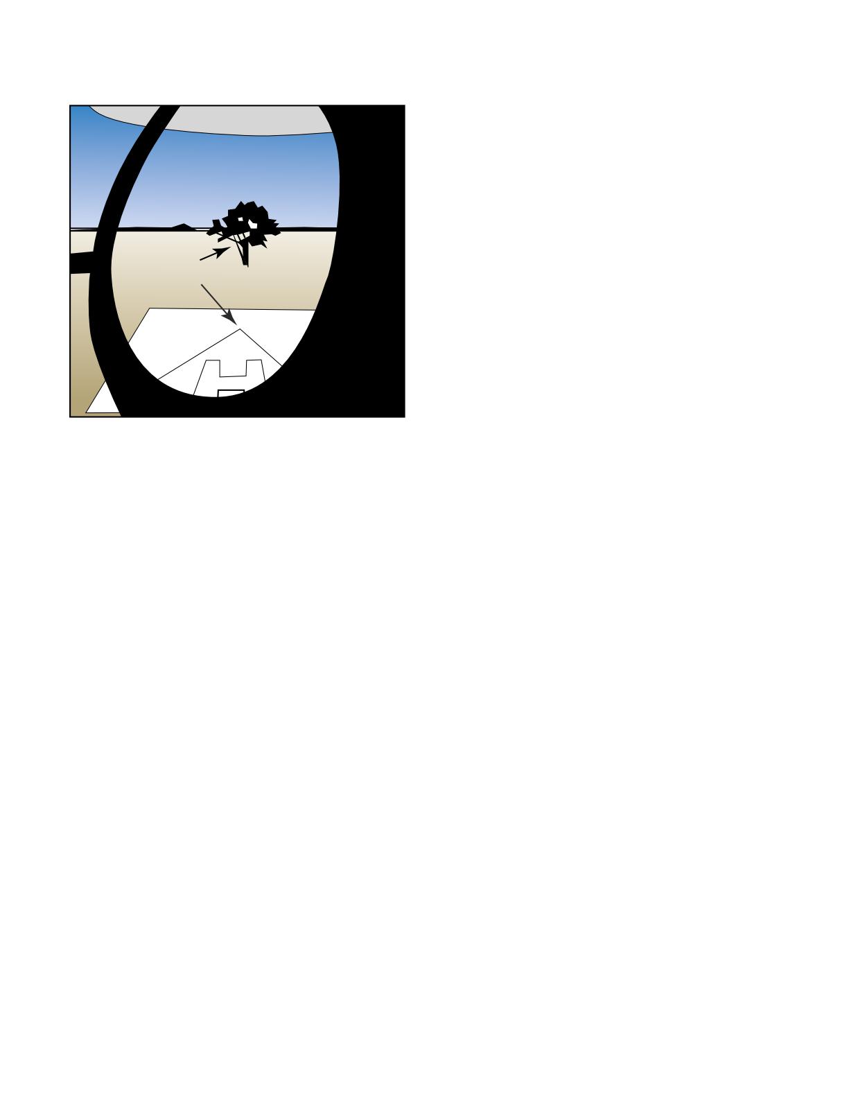
Figure 9-4. The key to hovering sideward is establishing at
least two reference points that help you maintain a straight
track over the ground while keeping a constant heading.
Begin the maneuver from a normal hovering altitude by
applying rearward pressure on the cyclic. After the
movement has begun, position the cyclic to maintain a
slow groundspeed (no faster than a brisk walk).
Begin the maneuver from a normal hovering altitude
Throughout the maneuver, maintain constant ground-
by applying cyclic toward the side in which the
speed and ground track with the cyclic, a constant
movement is desired. As the movement begins, return
heading with the antitorque pedals, constant altitude
the cyclic toward the neutral position to keep the
with the collective, and the proper r.p.m. with the throttle.
groundspeed at a slow rate-no faster than a brisk
walk. Throughout the maneuver, maintain a constant
To stop the rearward movement, apply forward cyclic
groundspeed and ground track with cyclic. Maintain
and hold it until the helicopter stops. As the motion
heading, which in this maneuver is perpendicular to
stops, return the cyclic to the neutral position. Also, as
the ground track, with the antitorque pedals, and a
in the case of forward and sideward hovering flight,
constant altitude with the collective. Use the throttle
opposite cyclic can be used to level the helicopter and
to maintain the proper operating r.p.m.
let it drift to a stop.
To stop the sideward movement, apply cyclic pres-
COMMON ERRORS
sure in the direction opposite to that of movement
1.
Exaggerated movement of the cyclic resulting in
and hold it until the helicopter stops. As motion
overcontrolling and an uneven movement over
stops, return the cyclic to the neutral position to
the surface.
prevent movement in the opposite direction.
Applying sufficient opposite cyclic pressure to
2.
Failure to use the antitorque pedals properly,
level the helicopter may also stop sideward move-
resulting in excessive heading change.
ment. The helicopter then drifts to a stop.
3.
Failure to maintain desired hovering altitude.
COMMON ERRORS
4.
Failure to maintain proper r.p.m.
1.
Exaggerated movement of the cyclic, resulting in
overcontrolling and erratic movement over the
5.
Failure to make sure the area is clear prior to
surface.
starting the maneuver.
2.
Failure to use proper antitorque pedal control,
TAXIING
resulting in excessive heading change.
Taxiing refers to operations on, or near the surface of
taxiways or other prescribed routes. In helicopters,
3.
Failure to maintain desired hovering altitude.
there are three different types of taxiing.
9-8

HOVER TAXI
r.p.m. with the throttle. Throughout the maneuver,
A "hover taxi" is used when operating below 25 feet
maintain a desired groundspeed and ground track with
AGL. [Figure 9-5] Since hover taxi is just like forward,
the cyclic, a constant heading with antitorque pedals,
sideward, or rearward hovering flight, the technique to
the desired altitude with the collective, and proper
perform it will not be presented here.
operating r.p.m. with the throttle.
To stop the forward movement, apply aft cyclic pressure
to reduce forward speed. Simultaneously lower the col-
Hover Taxi
(25 Feet or Less)
lective to initiate a descent to hover altitude. As
forward motion stops, return the cyclic to the neutral posi-
tion to prevent rearward movement. When at the proper
hover altitude, increase the collective as necessary.
COMMON ERRORS
1.
Erratic movement of the cyclic, resulting in
improper airspeed control and erratic movement
Poor Surface Conditions or Skid Type Helicopters
over the surface.
2.
Failure to use antitorque pedals properly, result-
Figure 9-5. Hover taxi.
ing in excessive heading changes.
3.
Failure to maintain desired altitude.
AIR TAXI
An "air taxi" is preferred when movements require
4.
Failure to maintain proper r.p.m.
greater distances within an airport or heliport bound-
5.
Overflying parked aircraft causing possible dam-
ary. [Figure 9-6] In this case, you basically fly to your
age from rotor downwash.
new location; however, you are expected to remain
below 100 feet AGL, and to avoid overflight of other
6.
Flying in the cross-hatched or shaded area of the
aircraft, vehicles, and personnel.
height-velocity diagram.
7.
Flying in a crosswind that could lead to loss of
Air Taxi
tail rotor effectiveness.
(100 Feet or Less)
SURFACE TAXI
A "surface taxi," for those helicopters with wheels, is
used whenever you wish to minimize the effects of
rotor downwash. [Figure 9-7]
Faster Travel
Surface Taxi
Figure 9-6. Air taxi.
TECHNIQUE
Before starting, determine the appropriate airspeed and
altitude combination to remain out of the cross-hatched
Less Rotor Downwash
or shaded areas of the height-velocity diagram.
Additionally, be aware of crosswind conditions that
Figure 9-7. Surface taxi.
could lead to loss of tail rotor effectiveness. Pick out
two references directly in front of the helicopter for the
ground path desired. These reference points should be
TECHNIQUE
kept in line throughout the maneuver.
The helicopter should be in a stationary position on the
surface with the collective full down and the r.p.m. the
Begin the maneuver from a normal hovering altitude
same as that used for a hover. This r.p.m. should be
by applying forward pressure on the cyclic. As move-
maintained throughout the maneuver. Then, move the
ment begins, attain the desired airspeed with the cyclic.
cyclic slightly forward and apply gradual upward pres-
Control the desired altitude with the collective, and
sure on the collective to move the helicopter forward
9-9
along the surface. Use the antitorque pedals to maintain
hover. Wind will necessitate some cyclic deflection,
heading and the cyclic to maintain ground track. The
but there should not be an extreme deviation from
collective controls starting, stopping, and speed while
neutral. Flight controls must move freely, and the hel-
taxiing. The higher the collective pitch, the faster the
icopter should respond normally. Then visually clear
taxi speed; however, you should not taxi faster than a
the area all around.
brisk walk. If your helicopter is equipped with brakes,
use them to help you slow down. Do not use the cyclic
Start the helicopter moving by smoothly and slowly eas-
to control groundspeed.
ing the cyclic forward (position 2). As the helicopter
starts to move forward, increase the collective, as nec-
During a crosswind taxi, hold the cyclic into the wind a
essary, to prevent the helicopter from sinking and adjust
sufficient amount to eliminate any drifting movement.
the throttle to maintain r.p.m. The increase in power
requires an increase in the proper antitorque pedal to
COMMON ERRORS
maintain heading. Maintain a straight takeoff path
1.
Improper use of cyclic.
throughout the takeoff. As you accelerate through effec-
tive translational lift (position 3), the helicopter begins
2.
Failure to use antitorque pedals for heading
to climb and the nose tends to rise due to increased lift.
control.
At this point adjust the collective to obtain normal climb
3.
Improper use of the controls during crosswind
power and apply enough forward cyclic to overcome
operations.
the tendency of the nose to rise. At position 4, hold an
attitude that allows a smooth acceleration toward climb-
4.
Failure to maintain proper r.p.m.
ing airspeed and a commensurate gain in altitude so that
the takeoff profile does not take you through any of the
NORMAL TAKEOFF FROM A HOVER
cross-hatched or shaded areas of the height-velocity
A normal takeoff from a hover is an orderly transition
diagram. As airspeed increases (position 5), the stream-
to forward flight and is executed to increase altitude
lining of the fuselage reduces engine torque effect,
safely and expeditiously. During the takeoff, fly a pro-
requiring a gradual reduction of antitorque pedal
file that avoids the cross-hatched or shaded areas of the
pressure. As the helicopter continues to climb and accel-
height-velocity diagram.
erate to best rate of climb, apply aft cyclic pressure to
raise the nose smoothly to the normal climb attitude.
TECHNIQUE
Refer to figure 9-8 (position 1). Bring the helicopter to
COMMON ERRORS
a hover and make a performance check, which
1.
Failing to use sufficient collective pitch to pre-
includes power, balance, and flight controls. The power
vent loss of altitude prior to attaining transla-
check should include an evaluation of the amount of
tional lift.
excess power available; that is, the difference between
the power being used to hover and the power available
2.
Adding power too rapidly at the beginning of the
at the existing altitude and temperature conditions. The
transition from hovering to forward flight without
balance condition of the helicopter is indicated by the
forward cyclic compensation, causing the helicopter
position of the cyclic when maintaining a stationary
to gain excessive altitude before acquiring airspeed.
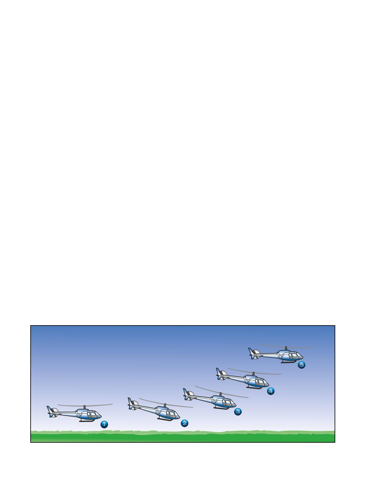
Figure 9-8. The helicopter takes several positions during a normal takeoff from a hover. The numbered positions in the text refer
to the numbers in this illustration.
9-10
3.
Assuming an extreme nose-down attitude near
the maneuver. [Figure 9-9] The cyclic is held into the
the surface in the transition from hovering to
wind a sufficient amount to maintain the desired
forward flight.
ground track for the takeoff. The heading is maintained
with the use of the antitorque pedals. In other words,
4.
Failing to maintain a straight flight path over the
the rotor is tilted into the wind so that the sideward
surface (ground track).
movement of the helicopter is just enough to counter-
act the crosswind effect. To prevent the nose from
5.
Failing to maintain proper airspeed during the
turning in the direction of the rotor tilt, it is necessary
climb.
to increase the antitorque pedal pressure on the side
opposite the rotor tilt.
6.
Failing to adjust the throttle to maintain proper
r.p.m.
NORMAL TAKEOFF FROM THE
SURFACE
Normal takeoff from the surface is used to move the
helicopter from a position on the surface into effective
translational lift and a normal climb using a minimum
amount of power. If the surface is dusty or covered with
Helicopter
Wind
loose snow, this technique provides the most favorable
Side Movement
Movement
visibility conditions and reduces the possibility of
debris being ingested by the engine.
TECHNIQUE
Figure 9-9. During a slip, the rotor disc is tilted into the wind.
Place the helicopter in a stationary position on the sur-
face. Lower the collective to the full down position,
and reduce the r.p.m. below operating r.p.m. Visually
After approximately 50 feet of altitude is gained, make
clear the area and select terrain features, or other
a coordinated turn into the wind to maintain the desired
objects, to aid in maintaining the desired track during
ground track. This is called crabbing into the wind. The
takeoff and climb out. Increase the throttle to the
stronger the crosswind, the more you have to turn the
proper r.p.m. and raise the collective slowly until the
helicopter into the wind to maintain the desired ground
helicopter is light on the skids. Hesitate momentarily
track. [Figure 9-10]
and adjust the cyclic and antitorque pedals, as neces-
sary, to prevent any surface movement. Continue to
apply upward collective and, as the helicopter breaks
ground, use the cyclic, as necessary, to begin forward
Helicopter Ground
Track
movement as altitude is gained. Continue to acceler-
Helicopter
Heading
ate, and as effective translational lift is attained, the
helicopter begins to climb. Adjust attitude and power,
if necessary, to climb in the same manner as a takeoff
from a hover.
Wind
COMMOM ERRORS
Movement
1.
Departing the surface in an attitude that is too
nose-low. This situation requires the use of exces-
sive power to initiate a climb.
2.
Using excessive power combined with a level
attitude, which causes a vertical climb.
3.
Too abrupt application of the collective when
departing the surface, causing r.p.m. and heading
control errors.
CROSSWIND CONSIDERATIONS
DURING TAKEOFFS
If the takeoff is made during crosswind conditions, the
Figure 9-10. To compensate for wind drift at altitude, crab the
helicopter is flown in a slip during the early stages of
helicopter into the wind.
9-11
cyclic to neutral slightly before the desired attitude is
STRAIGHT-AND-LEVEL FLIGHT
reached. This principal holds true for any cyclic input.
Straight-and-level flight is flight in which a constant
altitude and heading are maintained. The attitude of the
Since helicopters are inherently unstable, if a gust or
helicopter determines the airspeed and is controlled by
turbulence causes the nose to drop, the nose tends to
the cyclic. Altitude is primarily controlled by use of the
continue to drop instead of returning to a straight-and-
collective.
level attitude as would a fixed-wing aircraft.
Therefore, you must remain alert and FLY the helicop-
TECHNIQUE
ter at all times.
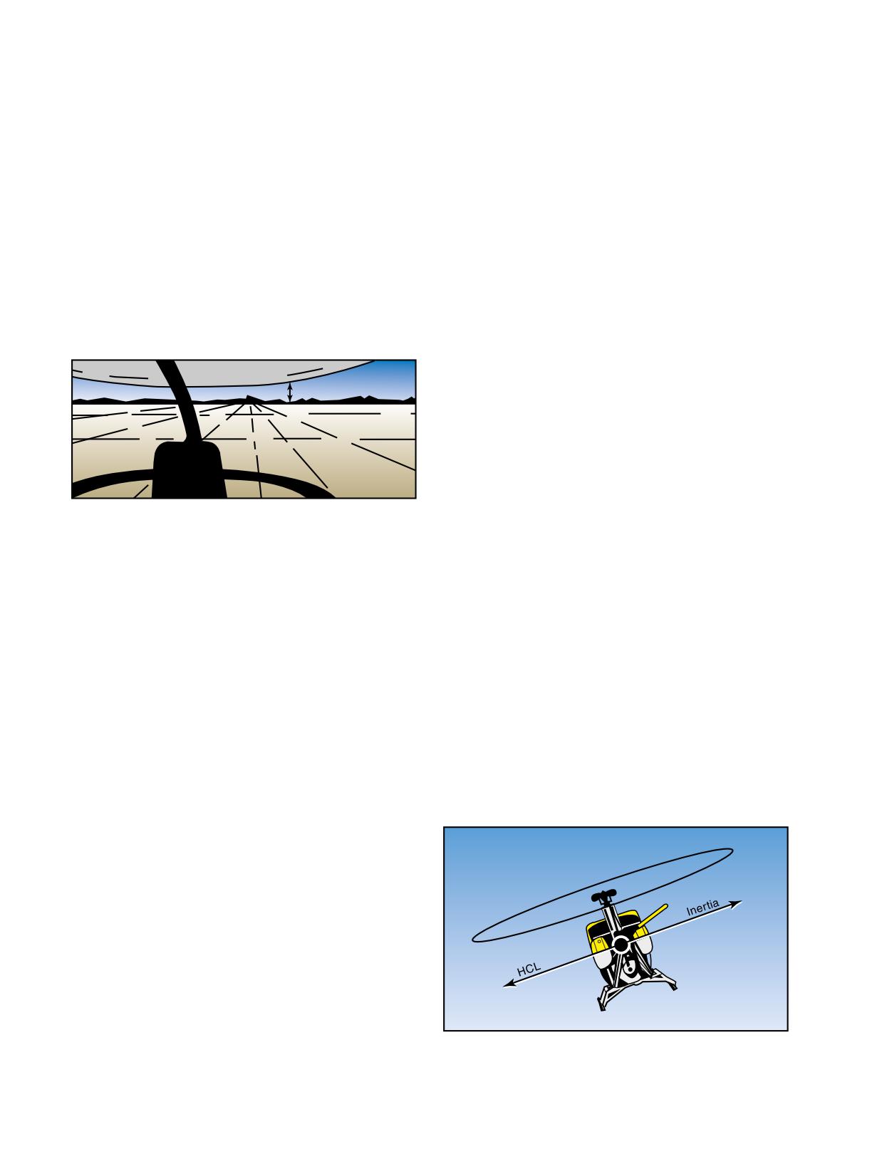
To maintain forward flight, the rotor tip-path plane must
be tilted forward to obtain the necessary horizontal
COMMON ERRORS
thrust component from the main rotor. This generally
1.
Failure to properly trim the helicopter, tending to
results in a nose-low attitude. The lower the nose, the
hold antitorque pedal pressure and opposite
greater the power required to maintain altitude, and the
cyclic. This is commonly called cross-controlling.
higher the resulting airspeed. Conversely, the greater
the power used, the lower the nose must be to maintain
2.
Failure to maintain desired airspeed.
altitude. [Figure 9-11]
3.
Failure to hold proper control position to main-
Tip-Path Plane
tain desired ground track.
TURNS
A turn is a maneuver used to change the heading of the
helicopter. The aerodynamics of a turn were previously
discussed in Chapter 3-Aerodynamics of Flight.
Figure 9-11. You can maintain a straight-and-level attitude by
TECHNIQUE
keeping the tip-path plane parallel to and a constant distance
Before beginning any turn, the area in the direction of
above or below the natural horizon. For any given airspeed,
this distance remains the same as long as you sit in the same
the turn must be cleared not only at the helicopter’s alti-
position in the same type of aircraft.
tude, but also above and below. To enter a turn from
straight-and-level flight, apply sideward pressure on
When in straight-and-level flight, any increase in the
the cyclic in the direction the turn is to be made. This is
collective, while holding airspeed constant, causes the
the only control movement needed to start the turn. Do
helicopter to climb. A decrease in the collective, while
not use the pedals to assist the turn. Use the pedals only
holding airspeed constant, causes the helicopter to
to compensate for torque to keep the helicopter in lon-
descend. A change in the collective requires a coordi-
gitudinal trim. [Figure 9-12]
nated change of the throttle to maintain a constant
r.p.m. Additionally, the antitorque pedals need to be
How fast the helicopter banks depends on how much
adjusted to maintain heading and to keep the helicopter
lateral cyclic pressure you apply. How far the helicop-
in longitudinal trim.
ter banks (the steepness of the bank) depends on how
long you displace the cyclic. After establishing the
To increase airspeed in straight-and-level flight, apply
proper bank angle, return the cyclic toward the neutral
forward pressure on the cyclic and raise the collective
position. Increase the collective and throttle to main-
as necessary to maintain altitude. To decrease airspeed,
apply rearward pressure on the cyclic and lower the
collective, as necessary, to maintain altitude.
Although the cyclic is sensitive, there is a slight delay
in control reaction, and it will be necessary to antici-
pate actual movement of the helicopter. When making
cyclic inputs to control the altitude or airspeed of a hel-
icopter, take care not to overcontrol. If the nose of the
helicopter rises above the level-flight attitude, apply
forward pressure to the cyclic to bring the nose down.
If this correction is held too long, the nose drops too
low. Since the helicopter continues to change attitude
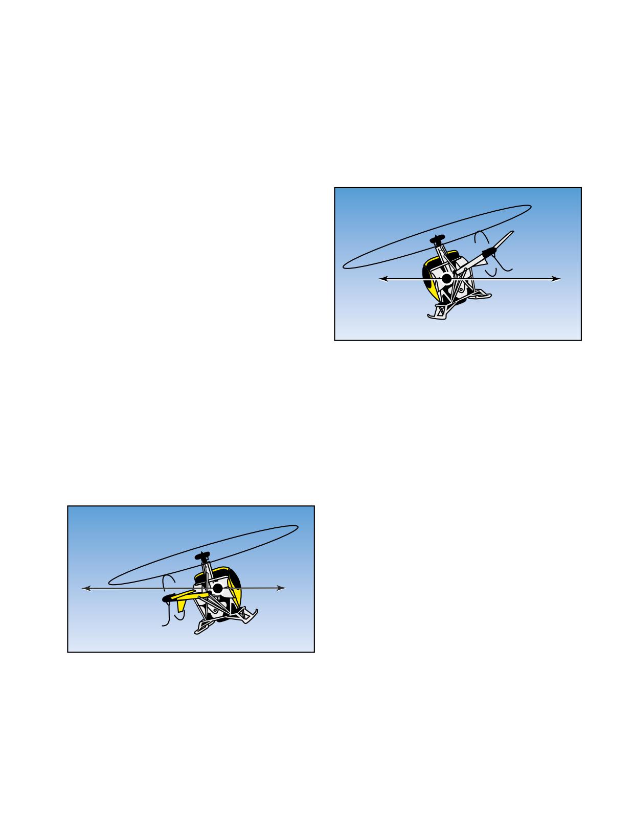
Figure 9-12. During a level, coordinated turn, the rate of turn
momentarily after the controls reach neutral, return the
is commensurate with the angle of bank used, and inertia and
horizontal component of lift (HCL) are equal.
9-12
tain altitude and r.p.m. As the torque increases, increase
opposite the turn in relation to the amount of power
the proper antitorque pedal pressure to maintain longi-
used. If the helicopter is forced to turn faster with
tudinal trim. Depending on the degree of bank, addi-
increased pedal pressure instead of by increasing the
tional forward cyclic pressure may be required to
degree of the bank, it skids sideways away from the
maintain airspeed.
center of the turn instead of flying in its normal curved
pattern.
Rolling out of the turn to straight-and-level flight is the
same as the entry into the turn except that pressure on
In summary, a skid occurs when the rate of turn is too
the cyclic is applied in the opposite direction. Since the
fast for the amount of bank being used, and a slip occurs
helicopter continues to turn as long as there is any bank,
when the rate of turn is too slow for the amount of bank
start the rollout before reaching the desired heading.
being used.
The discussion on level turns is equally applicable to
making turns while climbing or descending. The only
Skid
difference being that the helicopter is in a climbing or
descending attitude rather than that of level flight. If a
simultaneous entry is desired, merely combine the
techniques of both maneuvers-climb or descent
entry and turn entry. When recovering from a climbing
or descending turn, the desired heading and altitude are
HCL
Inertia
rarely reached at the same time. If the heading is
reached first, stop the turn and maintain the climb or
descent until reaching the desired altitude. On the
other hand, if the altitude is reached first, establish the
level flight attitude and continue the turn to the
Figure 9-14. During a skid, the rate of turn is too fast for the
desired heading.
angle of bank used, and inertia exceeds the horizontal com-
ponent of lift (HCL).
SLIPS
A slip occurs when the helicopter slides sideways
COMMON ERRORS
toward the center of the turn. [Figure 9-13] It is caused
1.
Using antitorque pedal pressures for turns. This is
by an insufficient amount of antitorque pedal in the
usually not necessary for small helicopters.
direction of the turn, or too much in the direction oppo-
site the turn, in relation to the amount of power used. In
2.
Slipping or skidding in the turn.
other words, if you hold improper antitorque pedal pres-
sure, which keeps the nose from following the turn, the
helicopter slips sideways toward the center of the turn.
NORMAL CLIMB
The entry into a climb from a hover has already been
discussed under “Normal Takeoff from a Hover;” there-
Slip
fore, this discussion is limited to a climb entry from
cruising flight.
TECHNIQUE
To enter a climb from cruising flight, apply aft cyclic to
obtain the approximate climb attitude. Simultaneously
HCL
Inertia
increase the collective and throttle to obtain climb
power and maintain r.p.m. In a counterclockwise rotor
system, increase the left antitorque pedal pressure to
compensate for the increased torque. As the airspeed
approaches normal climb airspeed, adjust the cyclic to
Figure 9-13. During a slip, the rate of turn is too slow for the
hold this airspeed. Throughout the maneuver, maintain
angle of bank used, and the horizontal component of lift
(HCL) exceeds inertia.
climb attitude, heading, and airspeed with the cyclic;
climb power and r.p.m. with the collective and throttle;
and longitudinal trim with the antitorque pedals.
SKIDS
A skid occurs when the helicopter slides sideways
To level off from a climb, start adjusting the attitude to the
away from the center of the turn. [Figure 9-14] It is
level flight attitude a few feet prior to reaching the desired
caused by too much antitorque pedal pressure in the
altitude. The amount of lead depends on the rate of climb
direction of the turn, or by too little in the direction
at the time of level-off (the higher the rate of climb, the
9-13
more the lead). Generally, the lead is 10 percent of the
2.
Failure to lead the level-off sufficiently, which
climb rate. For example, if your climb rate is 500 feet per
results in recovery below the desired altitude.
minute, you should lead the level-off by 50 feet.
3.
Failure to adjust antitorque pedal pressures for
changes in power.
To begin the level-off, apply forward cyclic to adjust
and maintain a level flight attitude, which is slightly
GROUND REFERENCE MANEUVERS
nose low. You should maintain climb power until the
airspeed approaches the desired cruising airspeed, then
Ground reference maneuvers are training exercises
lower the collective to obtain cruising power and adjust
flown to help you develop a division of attention
the throttle to obtain and maintain cruising r.p.m.
between the flight path and ground references, while
Throughout the level-off, maintain longitudinal trim
controlling the helicopter and watching for other air-
and heading with the antitorque pedals.
craft in the vicinity. Prior to each maneuver, a clearing
turn should be accomplished to ensure the practice area
COMMON ERRORS
is free of conflicting traffic.
1.
Failure to maintain proper power and airspeed.
RECTANGULAR COURSE
2.
Holding too much or too little antitorque pedal.
The rectangular course is a training maneuver in which
the ground track of the helicopter is equidistant from
3.
In the level-off, decreasing power before lower-
all sides of a selected rectangular area on the ground.
ing the nose to cruising attitude.
While performing the maneuver, the altitude and air-
speed should be held constant. The rectangular course
helps you to develop a recognition of a drift toward or
NORMAL DESCENT
away from a line parallel to the intended ground track.
A normal descent is a maneuver in which the helicop-
This is helpful in recognizing drift toward or from an
ter loses altitude at a controlled rate in a controlled
airport runway during the various legs of the airport
attitude.
traffic pattern.
TECHNIQUE
For this maneuver, pick a square or rectangular field,
To establish a normal descent from straight-and-level
or an area bounded on four sides by section lines or
flight at cruising airspeed, lower the collective to obtain
roads, where the sides are approximately a mile in
proper power, adjust the throttle to maintain r.p.m., and
length. The area selected should be well away from
increase right antitorque pedal pressure to maintain
other air traffic. Fly the maneuver approximately 600
heading in a counterclockwise rotor system, or left
to 1,000 feet above the ground, which is the altitude
pedal pressure in a clockwise system. If cruising
usually required for an airport traffic pattern. You
airspeed is the same as, or slightly above descending air-
should fly the helicopter parallel to and at a uniform
speed, simultaneously apply the necessary cyclic
distance, about one-fourth to one-half mile, from the
pressure to obtain the approximate descending attitude.
field boundaries, not above the boundaries. For best
If cruising speed is well above descending airspeed, you
results, position your flight path outside the field
can maintain a level flight attitude until the airspeed
boundaries just far enough away that they may be
approaches the descending airspeed, then lower the
easily observed from either pilot seat by looking out
nose to the descending attitude. Throughout the maneu-
the side of the helicopter. If an attempt is made to fly
ver, maintain descending attitude and airspeed with the
directly above the edges of the field, you will have
cyclic; descending power and r.p.m. with the collective
no usable reference points to start and complete the
and throttle; and heading with the antitorque pedals.
turns. In addition, the closer the track of the helicop-
ter is to the field boundaries, the steeper the bank
To level off from the descent, lead the desired altitude by
necessary at the turning points. Also, you should be
approximately 10 percent of the rate of descent. For exam-
able to see the edges of the selected field while seated
ple, a 500 feet per minute rate of descent would require a
in a normal position and looking out the side of the
50 foot lead. At this point, increase the collective to obtain
helicopter during either a left-hand or right-hand
cruising power, adjust the throttle to maintain r.p.m., and
course. The distance of the ground track from the
increase left antitorque pedal pressure to maintain heading
edges of the field should be the same regardless of
(right pedal pressure in a clockwise rotor system). Adjust
whether the course is flown to the left or right. All
the cyclic to obtain cruising airspeed and a level flight atti-
turns should be started when your helicopter is abeam
tude as the desired altitude is reached.
the corners of the field boundaries. The bank nor-
mally should not exceed 30°.
COMMON ERRORS
1.
Failure to maintain constant angle of decent dur-
Although the rectangular course may be entered from
ing training.
any direction, this discussion assumes entry on a
9-14
Enter
Start Turn
Pattern
No Crab
At Boundary
Turn More Than
Complete Turn
90°-Roll Out
At Boundary
With Crab Established
Turn More
Complete Turn
Than 90°
At Boundary
Start Turn
At Boundary
Crab Into
Crab Into
WIND
Wind
Wind
Turn less Than
Start Turn
90°-Roll Out
At Boundary
With Crab Established
Complete Turn
Turn Less
At Boundary
Than 90°
Start Turn
At Boundary
Complete Turn
At Boundary
No Crab
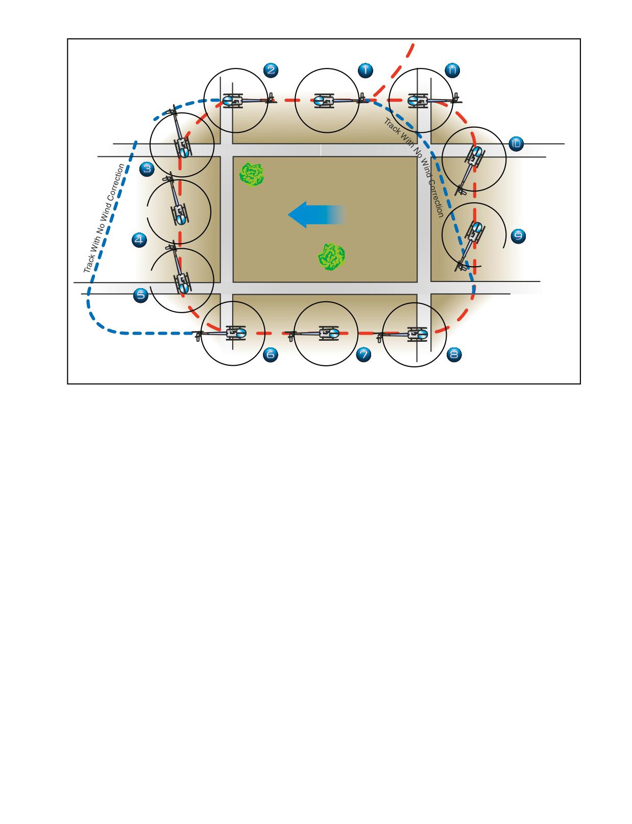
Figure 9-15. Rectangular course. The numbered positions in the text refer to the numbers in this illustration.
downwind heading. [Figure 9-15] As you approach the
necessary, to maintain a uniform distance from the field
field boundary on the downwind leg, you should begin
boundary (position 4).
planning for your turn to the crosswind leg. Since you
have a tailwind on the downwind leg, the helicopter's
As the next field boundary is being approached (posi-
groundspeed is increased (position 1). During the turn
tion 5), plan the turn onto the upwind leg. Since a wind
onto the crosswind leg, which is the equivalent of the
correction angle is being held into the wind and toward
base leg in a traffic pattern, the wind causes the heli-
the field while on the crosswind leg, this next turn
copter to drift away from the field. To counteract this
requires a turn of less than 90°. Since the crosswind
effect, the roll-in should be made at a fairly fast rate
becomes a headwind, causing the groundspeed to
with a relatively steep bank (position 2).
decrease during this turn, the bank initially must be
medium and progressively decreased as the turn pro-
As the turn progresses, the tailwind component
ceeds. To complete the turn, time the rollout so that the
decreases, which decreases the groundspeed.
helicopter becomes level at a point aligned with the
Consequently, the bank angle and rate of turn must be
corner of the field just as the longitudinal axis of the
reduced gradually to ensure that upon completion of
helicopter again becomes parallel to the field boundary
the turn, the crosswind ground track continues to be the
(position 6). The distance from the field boundary
same distance from the edge of the field. Upon comple-
should be the same as on the other sides of the field.
tion of the turn, the helicopter should be level and
aligned with the downwind corner of the field.
On the upwind leg, the wind is a headwind, which
However, since the crosswind is now pushing you
results in an decreased groundspeed (position
7).
away from the field, you must establish the proper drift
Consequently, enter the turn onto the next leg with a
correction by flying slightly into the wind. Therefore,
fairly slow rate of roll-in, and a relatively shallow bank
the turn to crosswind should be greater than a 90°
(position 8). As the turn progresses, gradually increase
change in heading (position 3). If the turn has been
the bank angle because the headwind component is
made properly, the field boundary again appears to be
diminishing, resulting in an increasing groundspeed.
one-fourth to one-half mile away. While on the cross-
During and after the turn onto this leg, the wind tends
wind leg, the wind correction should be adjusted, as
to drift the helicopter toward the field boundary. To
9-15
compensate for the drift, the amount of turn must be
less than 90° (position 9).
Points of
Again, the rollout from this turn must be such that as
WIND
Shallowest Bank
the helicopter becomes level, the nose of the helicopter
is turned slightly away the field and into the wind to
correct for drift. The helicopter should again be the
same distance from the field boundary and at the same
altitude, as on other legs. Continue the crosswind leg
until the downwind leg boundary is approached (posi-
tion 10). Once more you should anticipate drift and
Points of
turning radius. Since drift correction was held on the
Steepest Bank
crosswind leg, it is necessary to turn greater than 90° to
align the helicopter parallel to the downwind leg
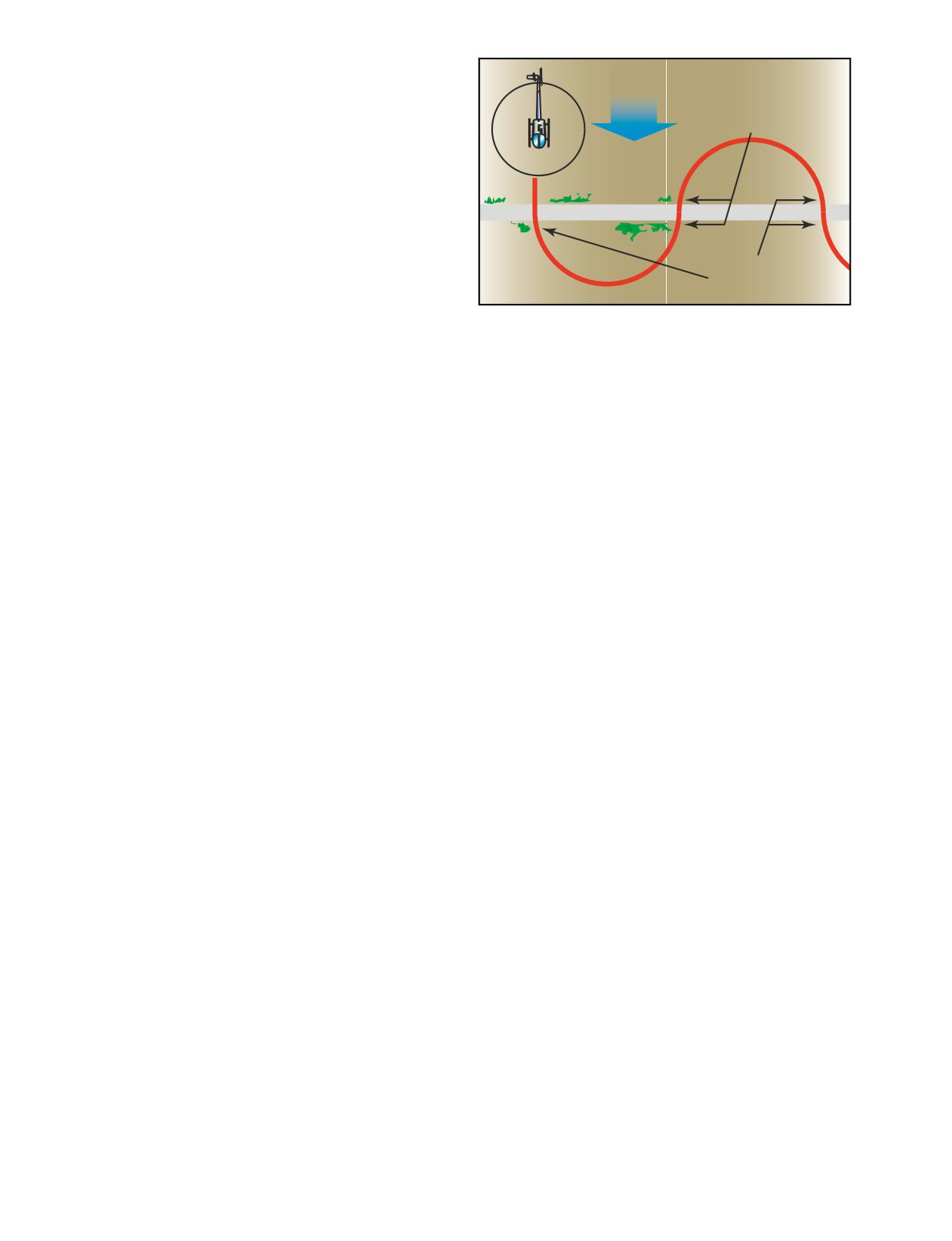
Figure 9-16. S-turns across a road.
boundary. Start this turn with a medium bank angle,
gradually increasing it to a steeper bank as the turn pro-
highest. Gradually reduce the bank, as necessary, to
gresses. Time the rollout to assure paralleling the
describe a ground track of a half circle. Time the turn
boundary of the field as the helicopter becomes level
so that as the rollout is completed, the helicopter is
(position 11).
crossing the reference line perpendicular to it and head-
If you have a direct headwind or tailwind on the
ing directly upwind. Immediately enter a bank in the
upwind and downwind leg, drift should not be encoun-
opposite direction to begin the second half of the “S.”
tered. However, it may be difficult to find a situation
Since the helicopter is now on an upwind heading, this
where the wind is blowing exactly parallel to the field
bank (and the one just completed before crossing the
boundaries. This makes it necessary to use a slight
reference line) is the shallowest in the maneuver.
wind correction angle on all the legs. It is important to
Gradually increase the bank, as necessary, to describe a
anticipate the turns to compensate for groundspeed,
ground track that is a half circle identical in size to the
drift, and turning radius. When the wind is behind the
one previously completed on the other side of the refer-
helicopter, the turn is faster and steeper; when it is
ence line. The steepest bank in this turn should be
ahead of the helicopter, the turn is slower and
attained just prior to rollout when the helicopter is
shallower. These same techniques apply while flying in
approaching the reference line nearest the downwind
an airport traffic pattern.
heading. Time the turn so that as the rollout is com-
plete, the helicopter is perpendicular to the reference
S-TURNS
line and is again heading directly downwind.
Another training maneuver you might use is the S-turn,
which helps you correct for wind drift in turns. This
In summary, the angle of bank required at any given
maneuver requires turns to the left and right. The refer-
point in the maneuver is dependent on the ground-
ence line used, whether a road, railroad, or fence, should
speed. The faster the groundspeed, the steeper the
be straight for a considerable distance and should
bank; the slower the groundspeed, the shallower
extend as nearly perpendicular to the wind as possible.
the bank. To express it another way, the more nearly
the helicopter is to a downwind heading, the steeper the
The object of S-turns is to fly a pattern of two half cir-
bank; the more nearly it is to an upwind heading,
cles of equal size on opposite sides of the reference line.
the shallower the bank. In addition to varying the angle
[Figure 9-16] The maneuver should be performed at a
of bank to correct for drift in order to maintain the
constant altitude between 600 and 1,000 feet above the
proper radius of turn, the helicopter must also be flown
terrain. S-turns may be started at any point; however,
with a drift correction angle (crab) in relation to its
during early training it may be beneficial to start on a
ground track; except of course, when it is on direct
downwind heading. Entering downwind permits the
upwind or downwind headings or there is no wind. One
immediate selection of the steepest bank that is desired
would normally think of the fore and aft axis of the heli-
throughout the maneuver. The discussion that follows is
copter as being tangent to the ground track pattern at
based on choosing a reference line that is perpendicular
each point. However, this is not the case. During the turn
to the wind and starting the maneuver on a downwind
on the upwind side of the reference line (side from
heading.
which the wind is blowing), crab the nose of the heli-
copter toward the outside of the circle. During the turn
As the helicopter crosses the reference line, immedi-
on the downwind side of the reference line (side of the
ately establish a bank. This initial bank is the steepest
reference line opposite to the direction from which the
used throughout the maneuver since the helicopter is
wind is blowing), crab the nose of the helicopter toward
headed directly downwind and the groundspeed is at its
the inside of the circle. In either case, it is obvious that
9-16
the helicopter is being crabbed into the wind just as it is
greatest, the steeper the bank, and the faster the rate
when trying to maintain a straight ground track. The
of turn required to establish the proper wind correc-
amount of crab depends upon the wind velocity and
tion angle. The more nearly it is to a direct upwind
how nearly the helicopter is to a crosswind position.
heading where the groundspeed is least, the shallower
The stronger the wind, the greater the crab angle at any
the bank, and the slower the rate of turn required to
given position for a turn of a given radius. The more
establish the proper wind correction angle. It follows,
nearly the helicopter is to a crosswind position, the
then, that throughout the maneuver, the bank and rate
greater the crab angle. The maximum crab angle should
of turn must be gradually varied in proportion to the
be at the point of each half circle farthest from the
groundspeed.
reference line.
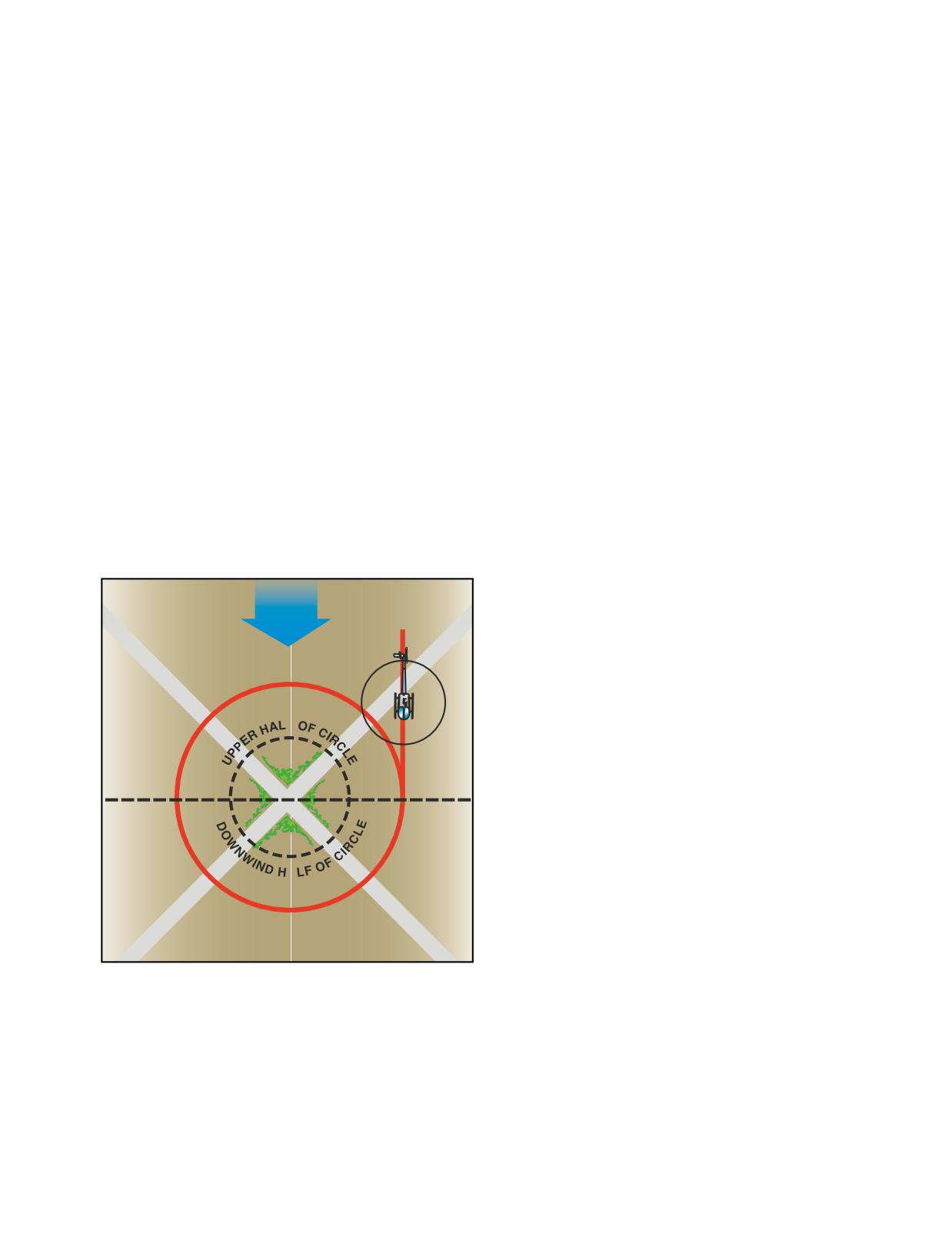
The point selected for turns around a point should be
Astandard radius for S-turns cannot be specified, since
prominent and easily distinguishable, yet small enough
the radius depends on the airspeed of the helicopter,
to present a precise reference. Isolated trees, crossroads,
the velocity of the wind, and the initial bank chosen
or other similar small landmarks are usually suitable.
for entry.
The point should be in an area away from communities,
livestock, or groups of people on the ground to prevent
TURNS AROUND A POINT
possible annoyance or hazard to others. Since the
This training maneuver requires you to fly constant
maneuver is performed between 600 and 1,000 feet
radius turns around a preselected point on the ground
AGL, the area selected should also afford an opportu-
using a bank of approximately 30°, while maintaining
nity for a safe emergency autorotation in the event it
a constant altitude. [Figure 9-17] Your objective, as in
becomes necessary.
other ground reference maneuvers, is to develop the
ability to subconsciously control the helicopter while
To enter turns around a point, fly the helicopter on a
dividing attention between the flight path and ground
downwind heading to one side of the selected point
references, while still watching for other air traffic in
at a distance equal to the desired radius of turn. When
the vicinity.
any significant wind exists, it is necessary to roll into
the initial bank at a rapid rate so that the steepest
bank is attained abeam the point when the helicopter
WIND
is headed directly downwind. By entering the maneu-
ver while heading directly downwind, the steepest
Steeper
bank can be attained immediately. Thus, if a bank of
Bank
30° is desired, the initial bank is 30° if the helicopter
is at the correct distance from the point. Thereafter,
the bank is gradually shallowed until the point is
F
reached where the helicopter is headed directly
upwind. At this point, the bank is gradually steepened
until the steepest bank is again attained when head-
Shallowest
Steepest
ing downwind at the initial point of entry.
Bank
Bank
Just as S-turns require that the helicopter be turned
into the wind in addition to varying the bank, so do
turns around a point. During the downwind half of the
A
circle, the helicopter’s nose must be progressively
turned toward the inside of the circle; during the
Shallower
upwind half, the nose must be progressively turned
Bank
toward the outside. The downwind half of the turn
around the point may be compared to the downwind
Figure 9-17. Turns around a point.
side of the S-turn, while the upwind half of the turn
around a point may be compared to the upwind side
of the S-turn.
The factors and principles of drift correction that are
involved in S-turns are also applicable in this maneu-
As you become experienced in performing turns
ver. As in other ground track maneuvers, a constant
around a point and have a good understanding of the
radius around a point will, if any wind exists, require
effects of wind drift and varying of the bank angle
a constantly changing angle of bank and angles of
and wind correction angle as required, entry into the
wind correction. The closer the helicopter is to a
maneuver may be from any point. When entering
direct downwind heading where the groundspeed is
this maneuver at any point, the radius of the turn
9-17
must be carefully selected, taking into account the
wind velocity and groundspeed so that an excessive
Downwind Leg
bank is not required later on to maintain the proper
ground track.
COMMON ERRORS DURING GROUND
REFERENCE MANEUVERS
1.
Faulty entry technique.
2.
Poor planning, orientation, or division of
Final Approach
Takeoff Leg
attention.
Leg
(Upwind)
3.
Uncoordinated flight control application.
4.
Improper correction for wind drift.
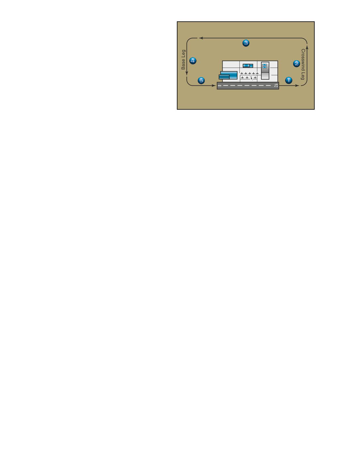
Figure 9-18. A standard traffic pattern has turns to left and
five designated legs.
5.
An unsymmetrical ground track during S-Turns
Across a Road.
6.
Failure to maintain selected altitude or airspeed.
flow of traffic when obstacles or highly populated areas
make the use of a left-hand pattern undesirable.
7.
Selection of a ground reference where there is no
suitable emergency landing area within gliding
When approaching an airport with an operating control
distance.
tower in a helicopter, it is possible to expedite traffic by
stating your intentions, for example:
TRAFFIC PATTERNS
A traffic pattern is useful to control the flow of traffic, par-
1.
(Call sign of helicopter) Robinson 8340J.
ticularly at airports without operating control towers. It
affords a measure of safety, separation, protection, and
2.
(Position) 10 miles west.
administrative control over arriving, departing, and
circling aircraft. Due to specialized operating character-
3.
(Request) for landing and hover to...
istics, airplanes and helicopters do not mix well in the
same traffic environment. At multiple-use airports,
In order to avoid the flow of fixed-wing traffic, the
you routinely must avoid the flow of fixed-wing traf-
tower will often clear you direct to an approach point
fic. To do this, you need to be familiar with the
or to a particular runway intersection nearest your
patterns typically flown by airplanes. In addition, you
destination point. At uncontrolled airports, if at all
should learn how to fly these patterns in case air traf-
possible, you should adhere to standard practices
fic control (ATC) requests that you fly a fixed-wing
and patterns.
traffic pattern.
Traffic pattern entry procedures at airports with an
A normal traffic pattern is rectangular, has five named
operating control tower are specified by the controller.
legs, and a designated altitude, usually 600 to 1,000
At uncontrolled airports, traffic pattern altitudes and
feet AGL. A pattern in which all turns are to the left is
entry procedures may vary according to established
called a standard pattern. [Figure 9-18] The takeoff leg
local procedures. The general procedure is for you to
(item 1) normally consists of the aircraft’s flight path
enter the pattern at a 45° angle to the downwind leg
after takeoff. This leg is also called the upwind leg. You
abeam the midpoint of the runway. For information
should turn to the crosswind leg (item 2), after passing
concerning traffic pattern and landing direction, you
the departure end of the runway when you are at a safe
should utilize airport advisory service or UNICOM,
altitude. Fly the downwind leg (item 3) parallel to the
when available.
runway at the designated traffic pattern altitude and
distance from the runway. Begin the base leg (item 4)
at a point selected according to other traffic and wind
The standard departure procedure when using the
conditions. If the wind is very strong, begin the turn
fixed-wing traffic pattern is usually straight-out, down-
sooner than normal. If the wind is light, delay the turn
wind, or a right-hand departure. When a control tower
to base. The final approach (item 5) is the path the air-
is in operation, you can request the type of departure
craft flies immediately prior to touchdown.
you desire. In most cases, helicopter departures are
made into the wind unless obstacles or traffic dictate
You may find variations at different localities and at
otherwise. At airports without an operating control
airports with operating control towers. For example, a
tower, you must comply with the departure procedures
right-hand pattern may be designated to expedite the
established for that airport.
9-18
APPROACHES
An approach is the transition from traffic pattern alti-
tude to either a hover or to the surface. The approach
should terminate at the hover altitude with the rate of
H
descent and groundspeed reaching zero at the same
time. Approaches are categorized according to the angle
of descent as normal, steep, or shallow. In this chapter
Imaginary
we will concentrate on the normal approach. Steep and
Centerline
shallow approaches are discussed in the next chapter.
You should use the type of approach best suited to the
existing conditions. These conditions may include
obstacles, size and surface of the landing area, density
altitude, wind direction and speed, and weight.
Regardless of the type of approach, it should always
be made to a specific, predetermined landing spot.
NORMAL APPROACH TO A HOVER
A normal approach uses a descent profile of between
8° and 12° starting at approximately 300 feet AGL.
TECHNIQUE
On final approach, at the recommended approach
airspeed and at approximately 300 feet AGL, align the
helicopter with the point of intended touchdown.
[Figure 9-19] After intercepting an approach angle of 8°
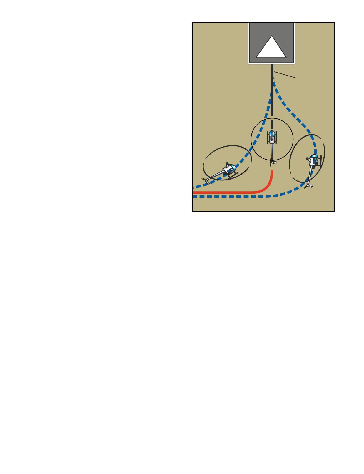
Figure 9-19. Plan the turn to final so the helicopter rolls out
to 12°, begin the approach by lowering the collective
on an imaginary extension of the centerline for the final
sufficiently to get the helicopter decelerating and
approach path. This path should neither angle to the land-
descending down the approach angle. With the decrease
ing area, as shown by the helicopter on the left, nor require
in the collective, the nose tends to pitch down, requiring
an S-turn, as shown by the helicopter on the right.
aft cyclic to maintain the recommended approach air-
speed attitude. Adjust antitorque pedals, as necessary, to
maintain longitudinal trim. You can determine the proper
As the helicopter approaches the recommended hover
approach angle by relating the point of intended
altitude, you need to increase the collective sufficiently
touchdown to a point on the helicopter windshield. The
to maintain the hover. At the same time you need to
collective controls the angle of approach. If the touch-
apply aft cyclic to stop any forward movement, while
down point seems to be moving up on the windshield, the
controlling the heading with antitorque pedals.
angle is becoming shallower, necessitating a slight
increase in collective. If the touchdown point moves
COMMON ERRORS
down on the windshield, the approach angle is becoming
1.
Failing to maintain proper r.p.m. during the entire
steeper, requiring a slight decrease in collective. Use the
approach.
cyclic to control the rate of closure or how fast your are
moving toward the touchdown point. Maintain entry
2.
Improper use of the collective in controlling the
airspeed until the apparent groundspeed and rate of
angle of descent.
closure appear to be increasing. At this point, slowly
begin decelerating with slight aft cyclic, and smoothly
3.
Failing to make antitorque pedal corrections to
lower the collective to maintain approach angle. Use the
compensate for collective changes during the
cyclic to maintain a rate of closure equivalent to a
approach.
brisk walk.
4.
Failing to simultaneously arrive at hovering alti-
At approximately 25 to 40 feet AGL, depending on wind,
tude and attitude with zero groundspeed.
the helicopter begins to lose effective translational lift. To
compensate for loss of effective translational lift, you
5.
Low r.p.m. in transition to the hover at the end of
must increase the collective to maintain the approach
the approach.
angle, while maintaining the proper r.p.m. The increase
of collective pitch tends to make the nose rise, requiring
6.
Using too much aft cyclic close to the surface,
forward cyclic to maintain the proper rate of closure.
which may result in tail rotor strikes.
9-19
NORMAL APPROACH TO THE SURFACE
A good rule of thumb to use during an approach is to
A normal approach to the surface or a no-hover landing is
make a go-around if the helicopter is in a position from
used if loose snow or dusty surface conditions exist.
which it is not safe to continue the approach. Anytime
These situations could cause severely restricted visibility,
you feel an approach is uncomfortable, incorrect, or
or the engine could possibly ingest debris when the heli-
potentially dangerous, abandon the approach. The deci-
copter comes to a hover. The approach is the same as the
sion to make a go-around should be positive and initiated
normal approach to a hover; however, instead of termi-
before a critical situation develops. When the decision is
nating at a hover, continue the approach to touchdown.
made, carry it out without hesitation. In most cases, when
Touchdown should occur with the skids level, zero
you initiate the go-around, power is at a low setting.
groundspeed, and a rate of descent approaching zero.
Therefore, your first response is to increase collective to
takeoff power. This movement is coordinated with the
TECHNIQUE:
throttle to maintain r.p.m., and the proper antitorque pedal
As the helicopter nears the surface, increase the collec-
to control heading. Then, establish a climb attitude and
tive, as necessary, to cushion the landing on the sur-
maintain climb speed to go around for another approach.
face, terminate in a skids-level attitude with no forward
movement.
AFTER LANDING AND SECURING
When the flight is terminated, park the helicopter
COMMON ERRORS
where it will not interfere with other aircraft and not
1.
Terminating at a hover, then making a vertical
be a hazard to people during shutdown. Rotor down-
landing.
wash can cause damage to other aircraft in close
proximity, and spectators may not realize the danger
2.
Touching down with forward movement.
or see the rotors turning. Passengers should remain in
the helicopter with their seats belts secured until the
3.
Approaching too slow, requiring the use of exces-
rotors have stopped turning. During the shutdown
sive power during the termination.
and postflight inspection, follow the manufacturer’s
checklist. Any discrepancies found should be noted
4.
Approaching too fast, causing a hard landing.
and, if necessary, reported to maintenance personnel.
CROSSWIND DURING APPROACHES
NOISE ABATEMENT PROCEDURES
During a crosswind approach, you should crab into the
The FAA, in conjunction with airport operators and
wind. At approximately 50 feet of altitude, use a slip to
community leaders, is now using noise abatement
align the fuselage with the ground track. The rotor is
procedures to reduce the level of noise generated by
tilted into the wind with cyclic pressure so that the
aircraft departing over neighborhoods that are near
sideward movement of the helicopter and wind drift
airports. The airport authority may simply request that
counteract each other. Maintain the heading and ground
you use a designated runway, wind permitting. You
track with the antitorque pedals. This technique should
also may be asked to restrict some of your operations,
be used on any type of crosswind approach, whether it is
such as practicing landings, during certain time peri-
a shallow, normal, or steep approach.
ods. There are three ways to determine the noise abate-
ment procedure at an airport. First, if there is a control
GO-AROUND
tower on the field, they will assign the preferred noise
A go-around is a procedure for remaining airborne after
abatement runway or takeoff direction to you. Second,
an intended landing is discontinued. A go-around may
you can check the Airport/Facility Directory for infor-
be necessary when:
mation on local procedures. Third, there may be infor-
mation for you to read in the pilot’s lounge, or even
•
Instructed by the control tower.
signs posted next to a runway that will advise you on
•
Traffic conflict occurs.
local procedures.
9-20
The maneuvers presented in this chapter require more
and small crevices. If everything is alright, you can
finesse and understanding of the helicopter and the
complete the approach to a landing. However, you must
surrounding environment. When performing these
make the decision to land or go-around before effective
maneuvers, you will probably be taking your helicopter
translational lift is lost.
to the edge of the safe operating envelope. Therefore, if
you are ever in doubt about the outcome of the maneuver,
If a decision is made to complete the approach, termi-
you should abort the mission entirely or wait for more
nate it in a hover, so you can carefully check the
favorable conditions.
landing point before lowering the helicopter to the
surface. Under certain conditions, it may be desirable
to continue the approach to the surface. Once the heli-
RECONNAISSANCE PROCEDURES
copter is on the ground, maintain operating r.p.m. until
Anytime you are planning to land or takeoff at an unfa-
you have checked the stability of the helicopter to be
miliar site, you should gather as much information as
sure it is in a secure and safe position.
you can about the area. Reconnaissance techniques are
ways of gathering this information.
GROUND RECONNAISSANCE
Prior to departing an unfamiliar location, make a
HIGH RECONNAISSANCE
detailed analysis of the area. There are several factors
The purpose of a high reconnaissance is to determine
to consider during this evaluation. Besides determining
the wind direction and speed, a point for touchdown,
the best departure path, you must select a route that will
the suitability of the landing area, the approach and
get your helicopter from its present position to the take-
departure axes, obstacles and their effect on wind pat-
off point.
terns, and the most suitable flight paths into and out of
the area. When conducting a high reconnaissance, give
Some things to consider while formulating a takeoff
particular consideration to forced landing areas in case
plan are the aircraft load, height of obstacles, the shape
of an emergency.
of the area, and direction of the wind. If the helicopter is
heavily loaded, you must determine if there is sufficient
Altitude, airspeed, and flight pattern for a high recon-
power to clear the obstacles. Sometimes it is better to
naissance are governed by wind and terrain features.
pick a path over shorter obstacles than to take off
You must strike a balance between a reconnaissance
directly into the wind. You should also evaluate the
conducted too high and one too low. It should not be
shape of the area so that you can pick a path that will
flown so low that you have to divide your attention
give you the most room to maneuver and abort the take-
between studying the area and avoiding obstructions to
off if necessary. Wind analysis also helps determine the
flight. A high reconnaissance should be flown at an alti-
route of takeoff. The prevailing wind can be altered by
tude of 300 to 500 feet above the surface. A general rule
obstructions on the departure path, and can significantly
to follow is to ensure that sufficient altitude is available
affect aircraft performance. One way to determine the
at all times to land into the wind in case of engine fail-
wind direction is to drop some dust or grass, and
ure. In addition, a 45° angle of observation generally
observe which way it is blowing. Keep in mind that if
allows the best estimate of the height of barriers, the
the main rotor is turning, you will need to be a sufficient
presence of obstacles, the size of the area, and the slope
distance from the helicopter to ensure that the down-
of the terrain. Always maintain safe altitudes and air-
wash of the blades does not give you a false indication.
speeds, and keep a forced landing area within reach
whenever possible.
If possible, you should walk the route from the helicop-
ter to the takeoff position. Evaluate obstacles that could
LOW RECONNAISSANCE
be hazardous and ensure that you will have adequate
A low reconnaissance is accomplished during the
rotor clearance. Once at the downwind end of the avail-
approach to the landing area. When flying the
able area, mark a position for takeoff so that the tail and
approach, verify what was observed in the high recon-
main rotors have sufficient clearance from any obstruc-
naissance, and check for anything new that may have
tions behind the helicopter. Use a sturdy marker, such
been missed at a higher altitude, such as wires, slopes,
as a heavy stone or log, so it does not blow away.
10-1
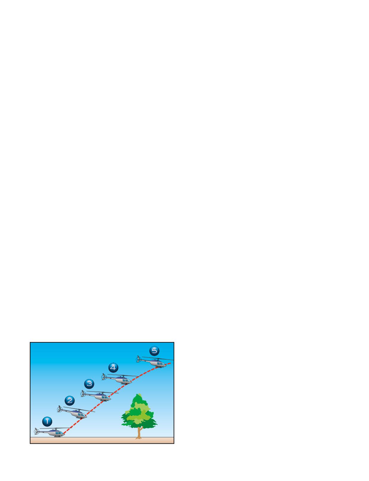
path to maintain ground track. You should also consider
MAXIMUM PERFORMANCE TAKEOFF
alternate routes in case you are not able to complete the
A maximum performance takeoff is used to climb at a
maneuver. [Figure 10-1]
steep angle to clear barriers in the flight path. It can be
used when taking off from small areas surrounded by
Begin the takeoff by getting the helicopter light on the
high obstacles. Before attempting a maximum
skids (position 1). Pause and neutralize all aircraft move-
performance takeoff, you must know thoroughly the
ment. Slowly increase the collective and position the
capabilities and limitations of your equipment. You
cyclic so as to break ground in a 40 knot attitude. This is
must also consider the wind velocity, temperature, alti-
approximately the same attitude as when the helicopter is
tude, gross weight, center-of-gravity location, and
light on the skids. Continue to slowly increase the collec-
other factors affecting your technique and the perform-
tive until the maximum power available is reached. This
ance of the helicopter.
large collective movement requires a substantial increase
in pedal pressure to maintain heading (position 2). Use the
To safely accomplish this type of takeoff, there must be
cyclic, as necessary, to control movement toward the
enough power to hover, in order to prevent the helicop-
desired flight path and, therefore, climb angle during the
ter from sinking back to the surface after becoming
maneuver (position 3). Maintain rotor r.p.m. at its maxi-
airborne. This hover power check can be used to deter-
mum, and do not allow it to decrease since you would
mine if there is sufficient power available to accomplish
probably have to lower the collective to regain it. Maintain
this maneuver.
these inputs until the helicopter clears the obstacle, or until
The angle of climb for a maximum performance take-
reaching 50 feet for demonstration purposes (position 4).
off depends on existing conditions. The more critical
Then, establish a normal climb attitude and reduce power
the conditions, such as high density altitudes, calm
(position 5). As in any maximum performance maneuver,
winds, and high gross weights, the shallower the angle
the techniques you use affect the actual results. Smooth,
of climb. In light or no wind conditions, it might be
coordinated inputs coupled with precise control allow the
necessary to operate in the crosshatched or shaded
helicopter to attain its maximum performance.
areas of the height/velocity diagram during the begin-
COMMON ERRORS
ning of this maneuver. Therefore, be aware of the
calculated risk when operating in these areas. An
1.
Failure to consider performance data, including
engine failure at a low altitude and airspeed could place
height/velocity diagram.
the helicopter in a dangerous position, requiring a high
2.
Nose too low initially, causing horizontal flight
degree of skill in making a safe autorotative landing.
rather than more vertical flight.
TECHNIQUE
3.
Failure to maintain maximum permissible r.p.m.
Before attempting a maximum performance takeoff,
4.
Abrupt control movements.
bring the helicopter to a hover, and determine the
5.
Failure to resume normal climb power and air-
excess power available by noting the difference
speed after clearing the obstacle.
between the power available and that required to hover.
You should also perform a balance and flight control
RUNNING/ROLLING TAKEOFF
check and note the position of the cyclic. Then position
A running takeoff in a skid-type helicopter or a rolling
the helicopter into the wind and return the helicopter to
takeoff in a wheeled helicopter is sometimes used when
the surface. Normally, this maneuver is initiated from
conditions of load and/or density altitude prevent a sus-
the surface. After checking the area for obstacles and
tained hover at normal hovering altitude. However, you
other aircraft, select reference points along the takeoff
should not attempt this maneuver if you do not have
sufficient power to hover, at least momentarily. If the
helicopter cannot be hovered, its performance is unpre-
dictable. If the helicopter cannot be raised off the
surface at all, sufficient power might not be available
to safely accomplish the maneuver. If you cannot
momentarily hover the helicopter, you must wait for
conditions to improve or off-load some of the weight.
To accomplish a safe running or rolling takeoff, the sur-
face area must be of sufficient length and smoothness,
and there cannot be any barriers in the flight path to
interfere with a shallow climb.
For wheeled helicopters, a rolling takeoff is sometimes
used to minimize the downwash created during a take-
Figure 10-1. Maximum performance takeoff.
off from a hover.
10-2
TECHNIQUE
2.
Attempting to become airborne before obtaining
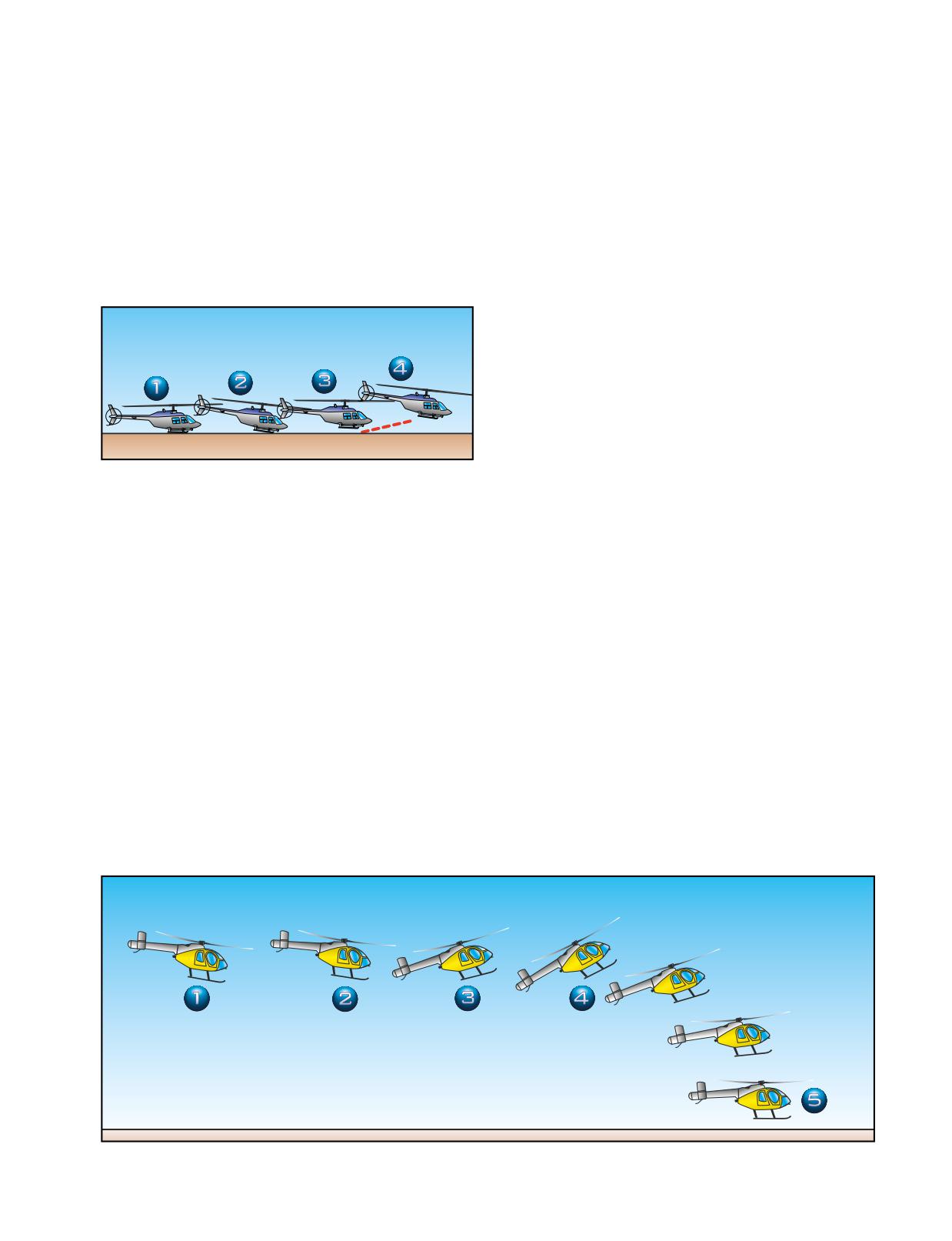
Refer to figure 10-2. To begin the maneuver, first align
effective translational lift.
the helicopter to the takeoff path. Next, increase the
3.
Using too much forward cyclic during the surface
throttle to obtain takeoff r.p.m., and increase the collec-
run.
tive smoothly until the helicopter becomes light on the
4.
Lowering the nose too much after becoming air-
skids or landing gear (position 1). Then, move the
borne, resulting in the helicopter settling back to
cyclic slightly forward of the neutral hovering position,
the surface.
and apply additional collective to start the forward
movement (position 2). To simulate a reduced power
5.
Failing to remain below the recommended altitude
condition during practice, use one to two inches less
until airspeed approaches normal climb speed.
manifold pressure, or three to five percent less torque,
than that required to hover.
RAPID DECELERATION (QUICK STOP)
In normal operations, use the rapid deceleration or quick
stop maneuver to slow the helicopter rapidly and bring
it to a stationary hover. The maneuver requires a high
degree of coordination of all controls. It is practiced at
an altitude that permits a safe clearance between the tail
rotor and the surface throughout the maneuver, espe-
cially at the point where the pitch attitude is highest.
The altitude at completion should be no higher than the
maximum safe hovering altitude prescribed by the man-
Figure 10-2. Running/rolling takeoff.
ufacturer. In selecting an altitude at which to begin the
maneuver, you should take into account the overall
length of the helicopter and the height/velocity diagram.
Even though the maneuver is called a rapid deceleration
or quick stop, it is performed slowly and smoothly with
Maintain a straight ground track with lateral cyclic and
the primary emphasis on coordination.
heading with antitorque pedals until a climb is established.
As effective translational lift is gained, the helicopter
TECHNIQUE
becomes airborne in a fairly level attitude with little or no
During training always perform this maneuver into the
pitching (position 3). Maintain an altitude to take advan-
wind. [Figure 10-3, position 1] After leveling off at an
tage of ground effect, and allow the airspeed to increase
altitude between 25 and 40 feet, depending on the man-
toward normal climb speed. Then, follow a climb profile
ufacturer’s recommendations, accelerate to the desired
that takes you through the clear area of the height/velocity
entry speed, which is approximately 45 knots for most
diagram (position 4). During practice maneuvers, after
training helicopters (position 2). The altitude you
you have climbed to an altitude of 50 feet, establish the
choose should be high enough to avoid danger to the
normal climb power setting and attitude.
tail rotor during the flare, but low enough to stay out of
the crosshatched or shaded areas of the height/velocity
COMMON ERRORS
diagram throughout the maneuver. In addition, this
1.
Failing to align heading and ground track to keep
altitude should be low enough that you can bring the
surface friction to a minimum.
helicopter to a hover during the recovery.
Figure 10-3. Rapid deceleration or quick stop.
10-3
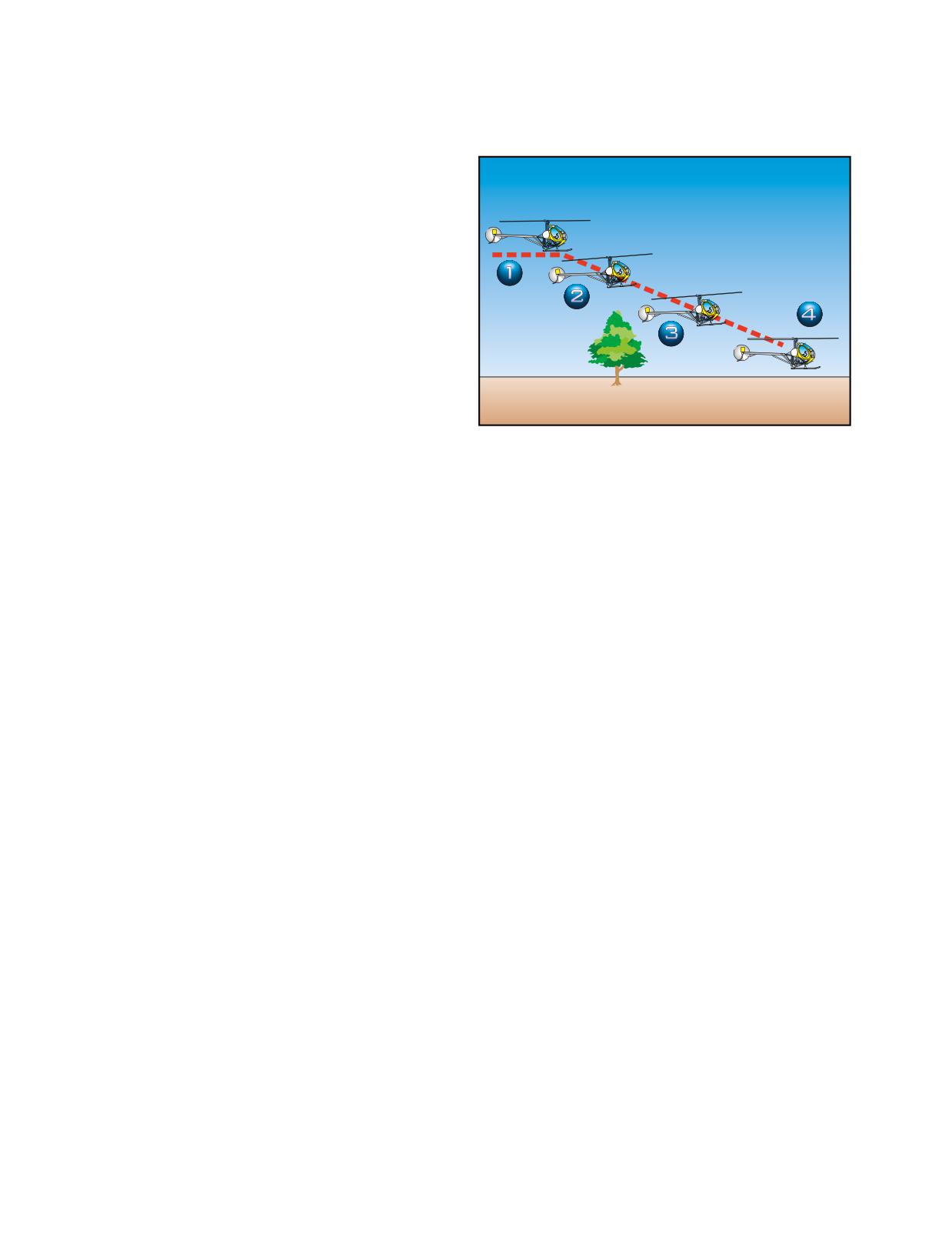
At position 3, initiate the deceleration by applying aft
most confined areas and is sometimes used to avoid
cyclic to reduce forward speed. Simultaneously, lower
areas of turbulence around a pinnacle. An approach
the collective, as necessary, to counteract any climbing
angle of approximately 15° is considered a steep
tendency. The timing must be exact. If you apply too
approach. [Figure 10-4]
little down collective for the amount of aft cyclic
applied, a climb results. If you apply too much down
collective, a descent results. A rapid application of aft
cyclic requires an equally rapid application of down
collective. As collective pitch is lowered, apply proper
15° Descent
antitorque pedal pressure to maintain heading, and
adjust the throttle to maintain r.p.m.
After attaining the desired speed (position 4), initiate
the recovery by lowering the nose and allowing the hel-
icopter to descend to a normal hovering altitude in level
flight and zero groundspeed (position 5). During the
recovery, increase collective pitch, as necessary, to stop
the helicopter at normal hovering altitude, adjust the
throttle to maintain r.p.m., and apply proper pedal pres-
sure, as necessary, to maintain heading.
Figure 10-4. Steep approach to a hover.
COMMON ERRORS
1.
Initiating the maneuver by applying down
collective.
TECHNIQUE
2.
Initially applying aft cyclic stick too rapidly,
On final approach, head your helicopter into the wind
causing the helicopter to balloon.
and align it with the intended touchdown point at the
recommended approach airspeed (position 1). When
3.
Failing to effectively control the rate of decelera-
you intercept an approach angle of 15°, begin the
tion to accomplish the desired results.
approach by lowering the collective sufficiently to
4.
Allowing the helicopter to stop forward motion
start the helicopter descending down the approach
in a tail-low attitude.
path and decelerating (position 2). Use the proper
antitorque pedal for trim. Since this angle is steeper
5.
Failing to maintain proper r.p.m.
than a normal approach angle, you need to reduce the
collective more than that required for a normal
6.
Waiting too long to apply collective pitch (power)
approach. Continue to decelerate with slight aft
during the recovery, resulting in excessive mani-
cyclic, and smoothly lower the collective to maintain
fold pressure or an over-torque situation when
the approach angle. As in a normal approach,
collective pitch is applied rapidly.
reference the touchdown point on the windshield to
7.
Failing to maintain a safe clearance over the
determine changes in approach angle. This point is in
terrain.
a lower position than a normal approach. Aft cyclic is
required to decelerate sooner than a normal approach,
8.
Improper use of antitorque pedals resulting in
and the rate of closure becomes apparent at a higher
erratic heading changes.
altitude. Maintain the approach angle and rate of
descent with the collective, rate of closure with the
cyclic, and trim with antitorque pedals. Use a crab
above 50 feet and a slip below 50 feet for any cross-
STEEP APPROACH TO A HOVER
wind that might be present.
A steep approach is used primarily when there are
obstacles in the approach path that are too high to allow
Loss of effective translational lift occurs higher in a
a normal approach. A steep approach permits entry into
steep approach (position 3), requiring an increase in the
collective to prevent settling, and more forward cyclic
to achieve the proper rate of closure. Terminate the
approach at hovering altitude above the intended land-
ing point with zero groundspeed (position 4). If power
has been properly applied during the final portion of
the approach, very little additional power is required in
Balloon-Gaining an excessive amount of altitude as a result of an
abrupt flare.
the hover.
10-4
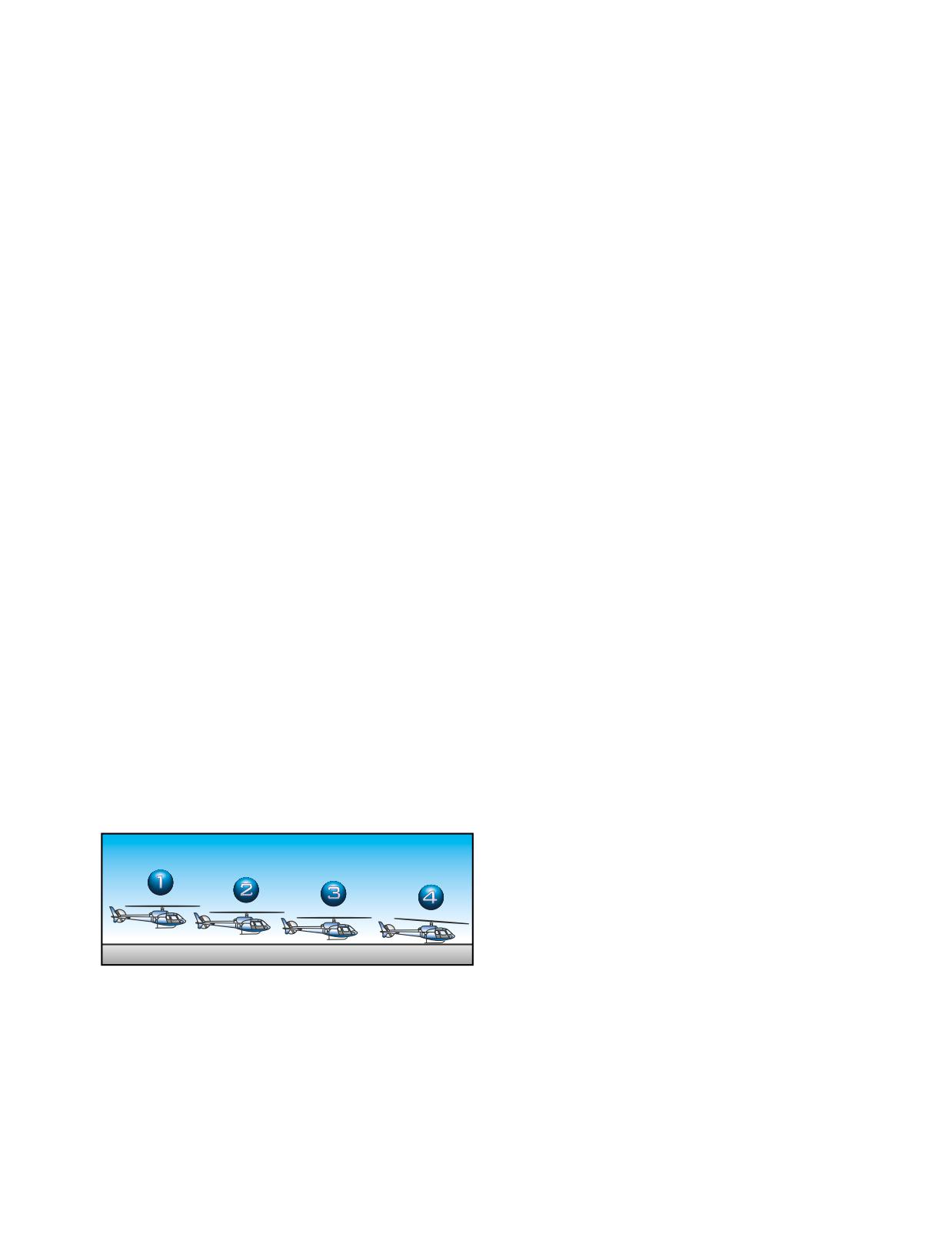
COMMON ERRORS
As you lower the collective, maintain heading with
proper antitorque pedal pressure, and r.p.m. with the
1.
Failing to maintain proper r.p.m. during the entire
throttle. Maintain approach airspeed until the apparent
approach.
rate of closure appears to be increasing. Then, begin to
2.
Improper use of collective in maintaining the
slow the helicopter with aft cyclic (position 2).
selected angle of descent.
As in normal and steep approaches, the primary control
3.
Failing to make antitorque pedal corrections to
for the angle and rate of descent is the collective, while
compensate for collective pitch changes during
the cyclic primarily controls the groundspeed.
the approach.
However, there must be a coordination of all the con-
4.
Slowing airspeed excessively in order to remain
trols for the maneuver to be accomplished successfully.
on the proper angle of descent.
The helicopter should arrive at the point of touchdown
at or slightly above effective translational lift. Since
5.
Inability to determine when effective transla-
translational lift diminishes rapidly at slow airspeeds,
tional lift is lost.
the deceleration must be smoothly coordinated, at the
6.
Failing to arrive at hovering altitude and attitude,
same time keeping enough lift to prevent the helicopter
and zero groundspeed almost simultaneously.
from settling abruptly.
7.
Low r.p.m. in transition to the hover at the end of
Just prior to touchdown, place the helicopter in a level
the approach.
attitude with the cyclic, and maintain heading with the
8.
Using too much aft cyclic close to the surface,
antitorque pedals. Use the cyclic to keep the heading
which may result in the tail rotor striking the sur-
and ground track identical (position 3). Allow the
face.
helicopter to descend gently to the surface in a straight-
and-level attitude, cushioning the landing with the
SHALLOW APPROACH AND
collective. After surface contact, move the cyclic
slightly forward to ensure clearance between the
RUNNING/ROLL-ON LANDING
tailboom and the rotor disc. You should also use the
Use a shallow approach and running landing when a
cyclic to maintain the surface track. (position 4). You
high-density altitude or a high gross weight condition,
normally hold the collective stationary until the heli-
or some combination thereof, is such that a normal or
copter stops; however, if you want more braking action,
steep approach cannot be made because of insufficient
you can lower the collective slightly. Keep in mind that
power to hover. [Figure 10-5] To compensate for this
due to the increased ground friction when you lower the
lack of power, a shallow approach and running landing
collective, the helicopter’s nose might pitch forward.
makes use of translational lift until surface contact is
Exercise caution not to correct this pitching movement
made. If flying a wheeled helicopter, you can also use a
with aft cyclic since this movement could result in the
roll-on landing to minimize the effect of downwash.
rotor making contact with the tailboom. During the
The glide angle for a shallow approach is approxi-
landing, maintain normal r.p.m. with the throttle and
mately 5°. Since the helicopter will be sliding or rolling
directional control with the antitorque pedals.
to a stop during this maneuver, the landing area must
be smooth and long enough to accomplish this task.
For wheeled helicopters, use the same technique except
after landing, lower the collective, neutralize the
controls, and apply the brakes, as necessary, to slow the
5° Descent
helicopter. Do not use aft cyclic when bringing the
helicopter to a stop.
COMMON ERRORS
1.
Assuming excessive nose-high attitude to slow
the helicopter near the surface.
Figure 10-5. Shallow approach and running landing.
2.
Insufficient collective and throttle to cushion
landing.
3.
Failing to add proper antitorque pedal as collec-
TECHNIQUE
tive is added to cushion landing, resulting in a
A shallow approach is initiated in the same manner as
touchdown while the helicopter is moving side-
the normal approach except that a shallower angle of
ward.
descent is maintained. The power reduction to initiate
the desired angle of descent is less than that for a normal
4.
Failing to maintain a speed that takes advantage
approach since the angle of descent is less (position 1).
of effective translational lift.
10-5
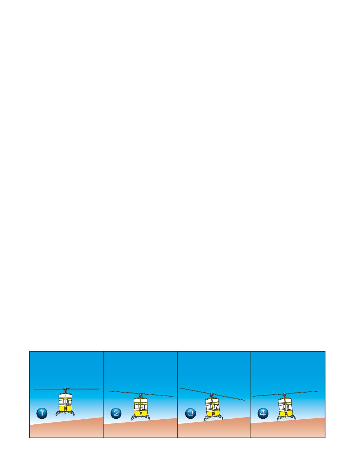
5.
Touching down at an excessive groundspeed for
can hold the helicopter against it with the cyclic during
the existing conditions. (Some helicopters have
the entire landing. A slope of 5° is considered maxi-
maximum touchdown groundspeeds.)
mum for normal operation of most helicopters.
6.
Failing to touch down in a level attitude.
You should be aware of any abnormal vibration or mast
7.
Failing to maintain proper r.p.m. during and after
bumping that signals maximum cyclic deflection. If
touchdown.
this occurs, abandon the landing because the slope is
too steep. In most helicopters with a counterclockwise
8.
Poor directional control during touchdown.
rotor system, landings can be made on steeper slopes
when you are holding the cyclic to the right. When
SLOPE OPERATIONS
landing on slopes using left cyclic, some cyclic input
Prior to conducting any slope operations, you should
must be used to overcome the translating tendency. If
be thoroughly familiar with the characteristics of
wind is not a factor, you should consider the drifting
dynamic rollover and mast bumping, which are dis-
tendency when determining landing direction.
cussed in Chapter 11-Helicopter Emergencies. The
approach to a slope is similar to the approach to any
After the downslope skid is on the surface, reduce the
other landing area. During slope operations, make
collective to full down, and neutralize the cyclic and
allowances for wind, barriers, and forced landing sites
pedals (frame 4). Normal operating r.p.m. should be
in case of engine failure. Since the slope may constitute
maintained until the full weight of the helicopter is on
an obstruction to wind passage, you should anticipate
the landing gear. This ensures adequate r.p.m. for
turbulence and downdrafts.
immediate takeoff in case the helicopter starts sliding
down the slope. Use antitorque pedals as necessary
SLOPE LANDING
throughout the landing for heading control. Before
You usually land a helicopter across the slope rather
reducing the r.p.m., move the cyclic control as neces-
than with the slope. Landing with the helicopter facing
sary to check that the helicopter is firmly on the
down the slope or downhill is not recommended
ground.
because of the possibility of striking the tail rotor on
the surface.
COMMON ERRORS
TECHNIQUE
1.
Failure to consider wind effects during the
Refer to figure 10-6. At the termination of the
approach and landing.
approach, move the helicopter slowly toward the slope,
2.
Failure to maintain proper r.p.m. throughout the
being careful not to turn the tail upslope. Position the
entire maneuver.
helicopter across the slope at a stabilized hover headed
into the wind over the spot of intended landing
3.
Turning the tail of the helicopter into the slope.
(frame 1). Downward pressure on the collective starts
4.
Lowering the downslope skid or wheel too rapidly.
the helicopter descending. As the upslope skid touches
the ground, hesitate momentarily in a level attitude,
5.
Applying excessive cyclic control into the slope,
then apply lateral cyclic in the direction of the slope
causing mast bumping.
(frame 2). This holds the skid against the slope while
you continue lowering the downslope skid with the col-
SLOPE TAKEOFF
lective. As you lower the collective, continue to move
A slope takeoff is basically the reverse of a slope land-
the cyclic toward the slope to maintain a fixed position
ing. [Figure 10-7] Conditions that may be associated
(frame 3). The slope must be shallow enough so you
with the slope, such as turbulence and obstacles, must
Figure 10-6. Slope landing.
10-6
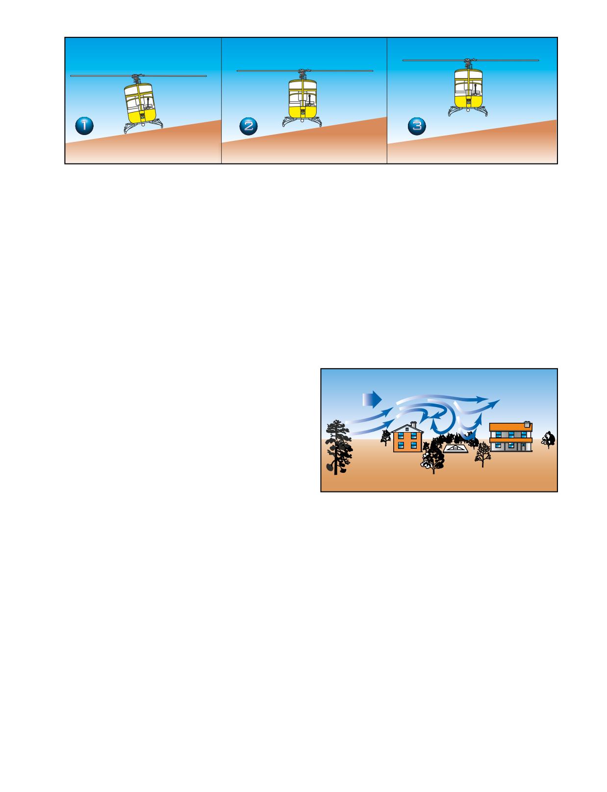
Figure 10-7. Slope takeoff.
be considered during the takeoff. Planning should
There are several things to consider when operating in
include suitable forced landing areas.
confined areas. One of the most important is maintaining
a clearance between the rotors and obstacles forming the
TECHNIQUE
confined area. The tail rotor deserves special considera-
Begin the takeoff by increasing r.p.m. to the normal
tion because, in some helicopters, you cannot always see
range with the collective full down. Then, move the
it from the cabin. This not only applies while making the
cyclic toward the slope (frame 1). Holding cyclic
approach, but while hovering as well. Another consider-
toward the slope causes the downslope skid to rise as
ation is that wires are especially difficult to see;
you slowly raise the collective (frame 2). As the skid
however, their supporting devices, such as poles or
comes up, move the cyclic toward the neutral position.
towers, serve as an indication of their presence and
If properly coordinated, the helicopter should attain a
approximate height. If any wind is present, you should
level attitude as the cyclic reaches the neutral position.
also expect some turbulence. [Figure 10-8]
At the same time, use antitorque pedal pressure to
maintain heading and throttle to maintain r.p.m. With
the helicopter level and the cyclic centered, pause
momentarily to verify everything is correct, and then
Wind
gradually raise the collective to complete the liftoff
(frame 3).
After reaching a hover, take care to avoid hitting the
ground with the tail rotor. If an upslope wind exists,
execute a crosswind takeoff and then make a turn into
the wind after clearing the ground with the tail rotor.
COMMON ERRORS
Figure 10-8. If the wind velocity is 10 knots or greater, you
should expect updrafts on the windward side and downdrafts
1.
Failure to adjust cyclic control to keep the heli-
on the lee side of obstacles. You should plan the approach
copter from sliding downslope.
with these factors in mind, but be ready to alter your plans if
the wind speed or direction changes.
2.
Failure to maintain proper r.p.m.
3.
Holding excessive cyclic into the slope as the
Something else for you to consider is the availability of
downslope skid is raised.
forced landing areas during the planned approach. You
4.
Turning the tail of the helicopter into the slope
should think about the possibility of flying from one
during takeoff.
alternate landing area to another throughout the
approach, while avoiding unfavorable areas. Always
CONFINED AREA OPERATIONS
leave yourself a way out in case the landing cannot be
A confined area is an area where the flight of the heli-
completed or a go-around is necessary.
copter is limited in some direction by terrain or the
presence of obstructions, natural or manmade. For
APPROACH
example, a clearing in the woods, a city street, a road, a
A high reconnaissance should be completed before ini-
building roof, etc., can each be regarded as a confined
tiating the confined area approach. Start the approach
area. Generally, takeoffs and landings should be made
phase using the wind and speed to the best possible
into the wind to obtain maximum airspeed with mini-
advantage. Keep in mind areas suitable for forced land-
mum groundspeed.
ing. It may be necessary to choose between an
10-7
approach that is crosswind, but over an open area, and
flight is required to reach the takeoff position, place
one directly into the wind, but over heavily wooded or
reference markers in front of the helicopter in such a
extremely rough terrain where a safe forced landing
way that a ground track can be safely followed to the
would be impossible. If these conditions exist, consider
takeoff position. In addition, the takeoff marker should
the possibility of making the initial phase of the
be located so that it can be seen without hovering
approach crosswind over the open area and then turn-
beyond it.
ing into the wind for the final portion of the approach.
When planning the takeoff, consider the direction of
Always operate the helicopter as close to its normal
the wind, obstructions, and forced landing areas. To
capabilities as possible, taking into consideration the
help you fly up and over an obstacle, you should form
situation at hand. In all confined area operations, with
an imaginary line from a point on the leading edge of
the exception of the pinnacle operation, the angle of
the helicopter to the highest obstacle to be cleared. Fly
descent should be no steeper than necessary to clear
this line of ascent with enough power to clear the
any barrier in the approach path and still land on the
obstacle by a safe distance. After clearing the obstacle,
selected spot. The angle of climb on takeoff should be
maintain the power setting and accelerate to the normal
normal, or not steeper than necessary to clear any bar-
climb speed. Then, reduce power to the normal climb
rier. Clearing a barrier by a few feet and maintaining
power setting.
normal operating r.p.m., with perhaps a reserve of
power, is better than clearing a barrier by a wide mar-
COMMON ERRORS
gin but with a dangerously low r.p.m. and no power
1.
Failure to perform, or improper performance of, a
reserve.
high or low reconnaissance.
2.
Flying the approach angle at too steep or too shal-
Always make the landing to a specific point and not to
low an approach for the existing conditions.
some general area. This point should be located well
forward, away from the approach end of the area. The
3.
Failing to maintain proper r.p.m.
more confined the area, the more essential it is that you
4.
Failure to consider emergency landing areas.
land the helicopter precisely at a definite point. Keep
5.
Failure to select a specific landing spot.
this point in sight during the entire final approach.
6.
Failure to consider how wind and turbulence
When flying a helicopter near obstructions, always
could affect the approach.
consider the tail rotor. A safe angle of descent over bar-
7.
Improper takeoff and climb technique for exist-
riers must be established to ensure tail rotor clearance
ing conditions.
of all obstructions. After coming to a hover, take care
to avoid turning the tail into obstructions.
PINNACLE AND RIDGELINE
OPERATIONS
TAKEOFF
A pinnacle is an area from which the surface drops
A confined area takeoff is considered an altitude over
away steeply on all sides. A ridgeline is a long area
airspeed maneuver. Before takeoff, make a ground
from which the surface drops away steeply on one or
reconnaissance to determine the type of takeoff to be
two sides, such as a bluff or precipice. The absence of
performed, to determine the point from which the take-
obstacles does not necessarily lessen the difficulty of
off should be initiated to ensure the maximum amount
pinnacle or ridgeline operations. Updrafts, downdrafts,
of available area, and finally, how to best maneuver the
and turbulence, together with unsuitable terrain in
helicopter from the landing point to the proposed take-
which to make a forced landing, may still present
off position.
extreme hazards.
If wind conditions and available area permit, the heli-
copter should be brought to a hover, turned around, and
APPROACH AND LANDING
hovered forward from the landing position to the take-
If you need to climb to a pinnacle or ridgeline, do it on
off position. Under certain conditions, sideward flight
the upwind side, when practicable, to take advantage of
to the takeoff position may be necessary. If rearward
any updrafts. The approach flight path should be paral-
lel to the ridgeline and into the wind as much as possi-
ble. [Figure 10-9]
Load, altitude, wind conditions, and terrain features
determine the angle to use in the final part of an
approach. As a general rule, the greater the winds, the
Altitude over Airspeed-In this type of maneuver, it is more important
to gain altitude than airspeed. However, unless operational considera-
steeper the approach needs to be to avoid turbulent air
tions dictate otherwise, the crosshatched or shaded areas of the
height/velocity diagram should be avoided.
and downdrafts. Groundspeed during the approach is
10-8
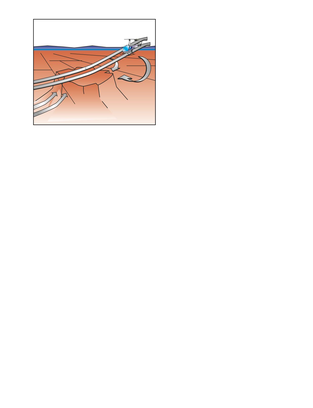
made in the forward portion of the area. Always per-
form a stability check, prior to reducing r.p.m., to
ensure the landing gear is on firm terrain that can safely
support the weight of the helicopter.
TAKEOFF
A pinnacle takeoff is an airspeed over altitude maneu-
ver made from the ground or from a hover. Since
pinnacles and ridgelines are generally higher than the
immediate surrounding terrain, gaining airspeed on the
takeoff is more important than gaining altitude. The
higher the airspeed, the more rapid the departure from
slopes of the pinnacle. In addition to covering unfavor-
able terrain rapidly, a higher airspeed affords a more
favorable glide angle and thus contributes to the
chances of reaching a safe area in the event of a forced
landing. If a suitable forced landing area is not avail-
Figure 10-9. When flying an approach to a pinnacle or ridge-
able, a higher airspeed also permits a more effective
line, avoid the areas where downdrafts are present, espe-
flare prior to making an autorotative landing.
cially when excess power is limited. If you encounter
downdrafts, it may become necessary to make an immediate
On takeoff, as the helicopter moves out of ground
turn away from the pinnacle to avoid being forced into the
effect, maintain altitude and accelerate to normal climb
rising terrain.
airspeed. When normal climb speed is attained, estab-
lish a normal climb attitude. Never dive the helicopter
more difficult to judge because visual references are
down the slope after clearing the pinnacle.
farther away than during approaches over trees or flat
terrain. If a crosswind exists, remain clear of down-
COMMON ERRORS
drafts on the leeward or downwind side of the
ridgeline. If the wind velocity makes the crosswind
1.
Failure to perform, or improper performance of, a
landing hazardous, you may be able to make a low,
high or low reconnaissance.
coordinated turn into the wind just prior to terminating
2.
Flying the approach angle at too steep or too shal-
the approach. When making an approach to a pinnacle,
low an approach for the existing conditions.
avoid leeward turbulence and keep the helicopter
within reach of a forced landing area as long as
3.
Failure to maintain proper r.p.m.
possible.
4.
Failure to consider emergency landing areas.
On landing, take advantage of the long axis of the area
5.
Failure to consider how wind and turbulence
when wind conditions permit. Touchdown should be
could affect the approach and takeoff.
Airspeed over Altitude-This means that in this maneuver, obstacles
are not a factor, and it is more important to gain airspeed than altitude.
10-9
10-10
Today helicopters are quite reliable. However
airspeed increases beyond that which gives minimum
emergencies do occur, whether a result of mechanical
rate of descent, the rate of descent increases again.
failure or pilot error. By having a thorough knowledge
of the helicopter and its systems, you will be able to
When landing from an autorotation, the energy stored
more readily handle the situation. In addition, by
in the rotating blades is used to decrease the rate of
knowing the conditions that can lead to an
descent and make a soft landing. A greater amount of
emergency, many potential accidents can be avoided.
rotor energy is required to stop a helicopter with a high
rate of descent than is required to stop a helicopter that
AUTOROTATION
is descending more slowly. Therefore, autorotative
In a helicopter, an autorotation is a descending maneu-
descents at very low or very high airspeeds are more
ver where the engine is disengaged from the main rotor
critical than those performed at the minimum rate of
system and the rotor blades are driven solely by the
descent airspeed.
upward flow of air through the rotor. In other words, the
engine is no longer supplying power to the main rotor.
Each type of helicopter has a specific airspeed at which
a power-off glide is most efficient. The best airspeed is
The most common reason for an autorotation is an
the one which combines the greatest glide range with
engine failure, but autorotations can also be performed
the slowest rate of descent. The specific airspeed is
in the event of a complete tail rotor failure, since there
somewhat different for each type of helicopter, yet
is virtually no torque produced in an autorotation. If
certain factors affect all configurations in the same
altitude permits, they can also be used to recover from
manner. For specific autorotation airspeeds for a partic-
settling with power. If the engine fails, the freewheel-
ular helicopter, refer to the FAA-approved rotorcraft
ing unit automatically disengages the engine from the
flight manual.
main rotor allowing the main rotor to rotate freely.
Essentially, the freewheeling unit disengages anytime
The specific airspeed for autorotations is established
the engine r.p.m. is less than the rotor r.p.m.
for each type of helicopter on the basis of average
weather and wind conditions and normal loading.
At the instant of engine failure, the main rotor blades
When the helicopter is operated with heavy loads in
are producing lift and thrust from their angle of attack
high density altitude or gusty wind conditions, best
and velocity. By immediately lowering collective pitch,
performance is achieved from a slightly increased air-
which must be done in case of an engine failure, lift and
speed in the descent. For autorotations at low density
drag are reduced, and the helicopter begins an immedi-
altitude and light loading, best performance is achieved
ate descent, thus producing an upward flow of air
from a slight decrease in normal airspeed. Following
through the rotor system. This upward flow of air
this general procedure of fitting airspeed to existing
through the rotor provides sufficient thrust to maintain
conditions, you can achieve approximately the same
rotor r.p.m. throughout the descent. Since the tail rotor
glide angle in any set of circumstances and estimate the
is driven by the main rotor transmission during autoro-
touchdown point.
tation, heading control is maintained as in normal flight.
When making turns during an autorotation, generally
Several factors affect the rate of descent in autorota-
use cyclic control only. Use of antitorque pedals to
tion; density altitude, gross weight, rotor r.p.m., and
assist or speed the turn causes loss of airspeed and
airspeed. Your primary control of the rate of descent is
downward pitching of the nose. When an autorotation
airspeed. Higher or lower airspeeds are obtained with
is initiated, sufficient antitorque pedal pressure should
the cyclic pitch control just as in normal flight.
be used to maintain straight flight and prevent yawing.
In theory, you have a choice in the angle of descent
This pressure should not be changed to assist the turn.
varying from a vertical descent to maximum range,
which is the minimum angle of descent. Rate of descent
is high at zero airspeed and decreases to a minimum at
Use collective pitch control to manage rotor r.p.m. If
approximately 50 to 60 knots, depending upon the par-
rotor r.p.m. builds too high during an autorotation, raise
ticular helicopter and the factors just mentioned. As the
the collective sufficiently to decrease r.p.m. back to the
11-1
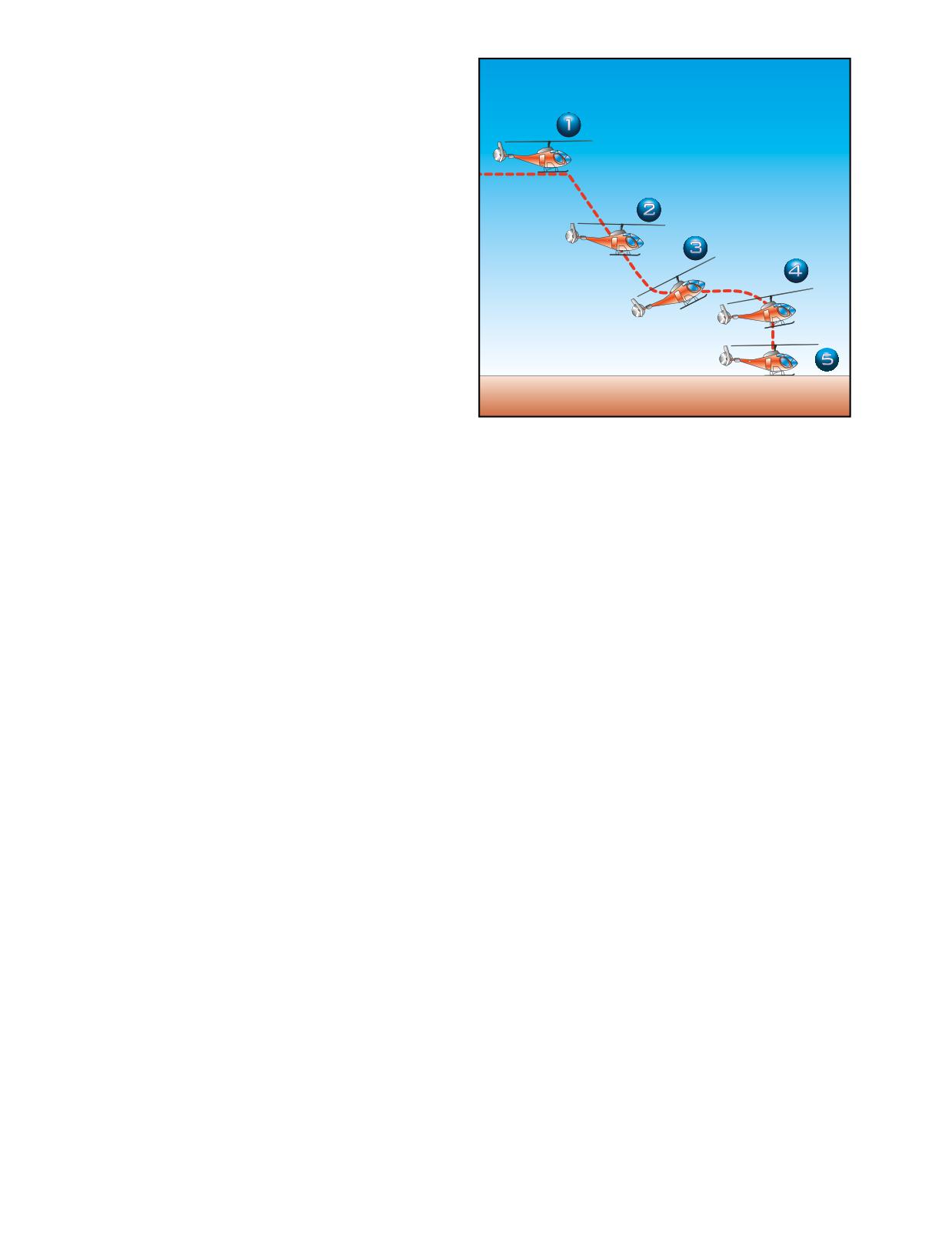
normal operating range. If the r.p.m. begins decreasing,
you have to again lower the collective. Always keep
the rotor r.p.m. within the established range for your
helicopter. During a turn, rotor r.p.m. increases due to
the increased back cyclic control pressure, which
induces a greater airflow through the rotor system. The
r.p.m. builds rapidly and can easily exceed the maxi-
mum limit if not controlled by use of collective. The
tighter the turn and the heavier the gross weight, the
higher the r.p.m.
To initiate an autorotation, other than in a low hover,
lower the collective pitch control. This holds true
whether performing a practice autorotation or in the
event of an in-flight engine failure. This reduces the
pitch of the main rotor blades and allows them to
continue turning at normal r.p.m. During practice
autorotations, maintain the r.p.m. in the green arc
with the throttle while lowering collective. Once the
collective is fully lowered, reduce engine r.p.m. by
Figure 11-1. Straight-in autorotation.
decreasing the throttle. This causes a split of the
engine and rotor r.p.m. needles.
and leads to “chasing the r.p.m.” Avoid looking straight
STRAIGHT-IN AUTOROTATION
down in front of the aircraft. Continually cross-check
A straight-in autorotation implies an autorotation from
attitude, trim, rotor r.p.m., and airspeed.
altitude with no turns. The speed at touchdown and the
resulting ground run depends on the rate and amount of
At approximately 40 to 100 feet above the surface, or
flare. The greater the degree of flare and the longer it is
at the altitude recommended by the manufacturer (posi-
held, the slower the touchdown speed and the shorter
tion 3), begin the flare with aft cyclic control to reduce
the ground run. The slower the speed desired at touch-
forward airspeed and decrease the rate of descent.
down, the more accurate the timing and speed of the
Maintain heading with the antitorque pedals. Care must
flare must be, especially in helicopters with low inertia
be taken in the execution of the flare so that the cyclic
rotor systems.
control is not moved rearward so abruptly as to cause
the helicopter to climb, nor should it be moved so
TECHNIQUE
slowly as to not arrest the descent, which may allow
Refer to figure 11-1 (position 1). From level flight at
the helicopter to settle so rapidly that the tail rotor
the manufacturer’s recommended airspeed, between
strikes the ground. When forward motion decreases to
500 to 700 feet AGL, and heading into the wind,
the desired groundspeed, which is usually the slowest
smoothly, but firmly lower the collective pitch control
possible speed (position 4), move the cyclic control
to the full down position, maintaining r.p.m. in the
forward to place the helicopter in the proper attitude
green arc with throttle. Coordinate the collective move-
for landing.
ment with proper antitorque pedal for trim, and apply
aft cyclic control to maintain proper airspeed. Once the
The altitude at this time should be approximately 8 to
collective is fully lowered, decrease throttle to ensure a
15 feet AGL, depending on the altitude recommended
clean split of the needles. After splitting the needles,
by the manufacturer. Extreme caution should be used
readjust the throttle to keep engine r.p.m. above
to avoid an excessive nose high and tail low attitude
normal idling speed, but not high enough to cause
below 10 feet. At this point, if a full touchdown landing
rejoining of the needles. The manufacturer often
is to be made, allow the helicopter to descend vertically
recommends the proper r.p.m.
(position 5). Increase collective pitch, as necessary, to
check the descent and cushion the landing. Additional
At position 2, adjust attitude with cyclic control to
antitorque pedal is required to maintain heading as col-
obtain the manufacturer’s recommended autorotation
lective pitch is raised due to the reduction in rotor
or best gliding speed. Adjust collective pitch control, as
r.p.m. and the resulting reduced effect of the tail rotor.
necessary, to maintain rotor r.p.m. in the green arc. Aft
Touch down in a level flight attitude.
cyclic movements cause an increase in rotor r.p.m.,
which is then controlled by a small increase in collec-
A power recovery can be made during training in lieu
tive pitch control. Avoid a large collective pitch
of a full touchdown landing. Refer to the section on
increase, which results in a rapid decay of rotor r.p.m.,
power recoveries for the correct technique.
11-2
After touchdown and after the helicopter has come to a
COMMON ERRORS
complete stop, lower the collective pitch to the full-
1.
Initiating recovery too late, requiring a rapid appli-
down position. Do not try to stop the forward ground
cation of controls, resulting in overcontrolling.
run with aft cyclic, as the main rotor blades can strike
the tail boom. Rather, by lowering the collective
2.
Failing to obtain and maintain a level attitude
slightly during the ground run, more weight is placed
near the surface.
on the undercarriage, slowing the helicopter.
3.
Failing to coordinate throttle and collective pitch
COMMON ERRORS
properly, resulting in either an engine overspeed
or a loss of r.p.m.
1.
Failing to use sufficient antitorque pedal when
power is reduced.
4.
Failing to coordinate proper antitorque pedal with
the increase in power
2.
Lowering the nose too abruptly when power is
reduced, thus placing the helicopter in a dive.
AUTOROTATIONS WITH TURNS
A turn, or a series of turns, can be made during an
3.
Failing to maintain proper rotor r.p.m. during
autorotation in order to land into the wind or avoid
the descent.
obstacles. The turn is usually made early so that the
4.
Application of up-collective pitch at an excessive
remainder of the autorotation is the same as a straight
altitude resulting in a hard landing, loss of
in autorotation. The most common types are 90° and
heading control, and possible damage to the tail
180° autorotations. The technique below describes a
rotor and to the main rotor blade stops.
180° autorotation.
5.
Failing to level the helicopter.
TECHNIQUE
Establish the aircraft on downwind at recommended
POWER RECOVERY FROM PRACTICE
airspeed at 700 feet AGL, parallel to the touchdown area.
AUTOROTATION
In a no wind or headwind condition, establish the ground
A power recovery is used to terminate practice
track approximately 200 feet away from the touchdown
autorotations at a point prior to actual touchdown.
point. If a strong crosswind exists, it will be necessary to
After the power recovery, a landing can be made or a
move your downwind leg closer or farther out. When
go-around initiated.
abeam the intended touchdown point, reduce
collective, and then split the needles. Apply proper
TECHNIQUE
antitorque pedal and cyclic to maintain proper attitude.
At approximately 8 to 15 feet above the ground,
Cross check attitude, trim, rotor r.p.m., and airspeed.
depending upon the helicopter being used, begin to
level the helicopter with forward cyclic control. Avoid
After the descent and airspeed is established, roll into a
excessive nose high, tail low attitude below 10 feet.
180° turn. For training, you should initially roll into a
Just prior to achieving level attitude, with the nose still
bank of a least 30°, but no more than 40°. Check your
slightly up, coordinate upward collective pitch control
airspeed and rotor r.p.m. Throughout the turn, it is
with an increase in the throttle to join the needles at
important to maintain the proper airspeed and keep the
operating r.p.m. The throttle and collective pitch must
aircraft in trim. Changes in the aircraft’s attitude and
be coordinated properly. If the throttle is increased too
the angle of bank cause a corresponding change in rotor
fast or too much, an engine overspeed can occur; if
r.p.m. Adjust the collective, as necessary, in the turn to
throttle is increased too slowly or too little in propor-
maintain rotor r.p.m. in the green arc.
tion to the increase in collective pitch, a loss of rotor
r.p.m. results. Use sufficient collective pitch to stop the
At the 90° point, check the progress of your turn by
descent and coordinate proper antitorque pedal
glancing toward your landing area. Plan the second
pressure to maintain heading. When a landing is to be
90 degrees of turn to roll out on the centerline. If you are
made following the power recovery, bring the helicop-
too close, decrease the bank angle; if too far out, increase
ter to a hover at normal hovering altitude and then
the bank angle. Keep the helicopter in trim with anti-
descend to a landing.
torque pedals.
If a go-around is to be made, the cyclic control should
The turn should be completed and the helicopter
be moved forward to resume forward flight. In transi-
aligned with the intended touchdown area prior to pass-
tioning from a practice autorotation to a go-around,
ing through 100 feet AGL. If the collective pitch was
exercise care to avoid an altitude-airspeed combination
increased to control the r.p.m., it may have to be
that would place the helicopter in an unsafe area of its
lowered on roll out to prevent a decay in r.p.m. Make
height-velocity diagram.
an immediate power recovery if the aircraft is not
11-3
aligned with the touchdown point, and if the rotor
When the weight of the helicopter is entirely on the
r.p.m. and/or airspeed is not within proper limits.
skids, cease the application of upward collective. When
the helicopter has come to a complete stop, lower the
From this point, complete the procedure as if it were a
collective pitch to the full down position.
straight-in autorotation.
The timing of the collective pitch is a most important
POWER FAILURE IN A HOVER
consideration. If it is applied too soon, the remaining
Power failures in a hover, also called hovering autoro-
r.p.m. may not be sufficient to make a soft landing. On
tations, are practiced so that you automatically make
the other hand, if collective pitch control is applied too
the correct response when confronted with engine
late, surface contact may be made before sufficient
stoppage or certain other emergencies while hovering.
blade pitch is available to cushion the landing.
The techniques discussed in this section refer to heli-
copters with a counter-clockwise rotor system and an
COMMON ERRORS
antitorque rotor.
1.
Failing to use sufficient proper antitorque pedal
TECHNIQUE
when power is reduced.
To practice hovering autorotations, establish a normal
hovering altitude for the particular helicopter being
2.
Failing to stop all sideward or backward move-
used, considering load and atmospheric conditions.
ment prior to touchdown.
Keep the helicopter headed into the wind and hold
maximum allowable r.p.m.
3.
Failing to apply up-collective pitch properly,
resulting in a hard touchdown.
To simulate a power failure, firmly roll the throttle into
the spring loaded override position, if applicable. This
4.
Failing to touch down in a level attitude.
disengages the driving force of the engine from the
rotor, thus eliminating torque effect. As the throttle is
5.
Not rolling the throttle completely to idle.
closed, apply proper antitorque pedal to maintain head-
ing. Usually, a slight amount of right cyclic control is
HEIGHT/VELOCITY DIAGRAM
necessary to keep the helicopter from drifting to the
A height/velocity (H/V) diagram, published by the
left, to compensate for the loss of tail rotor thrust.
manufacturer for each model of helicopter, depicts the
However, use cyclic control, as required, to ensure a
critical combinations of airspeed and altitude should an
vertical descent and a level attitude. Leave the collec-
engine failure occur. Operating at the altitudes and air-
tive pitch where it is on entry.
speeds shown within the crosshatched or shaded areas
of the H/V diagram may not allow enough time for the
Helicopters with low inertia rotor systems will begin to
critical transition from powered flight to autorotation.
settle immediately. Keep a level attitude and ensure a
[Figure 11-2]
vertical descent with cyclic control while maintaining
heading with the pedals. At approximately 1 foot above
An engine failure in a climb after takeoff occurring in
the surface, apply upward collective pitch control, as
section A of the diagram is most critical. During a
necessary, to slow the descent and cushion the landing.
climb, a helicopter is operating at higher power settings
Usually the full amount of collective pitch is required.
and blade angle of attack. An engine failure at this point
As upward collective pitch control is applied, the throt-
causes a rapid rotor r.p.m. decay because the upward
tle has to be held in the closed position to prevent the
movement of the helicopter must be stopped, then a
rotor from re-engaging.
descent established in order to drive the rotor. Time is
also needed to stabilize, then increase the r.p.m. to the
Helicopters with high inertia rotor systems will maintain
normal operating range. The rate of descent must reach
altitude momentarily after the throttle is closed. Then, as
a value that is normal for the airspeed at the moment.
the rotor r.p.m. decreases, the helicopter starts to settle.
Since altitude is insufficient for this sequence, you end
When the helicopter has settled to approximately 1 foot
up with decaying r.p.m., an increasing sink rate, no
above the surface, apply upward collective pitch control
deceleration lift, little translational lift, and little
while holding the throttle in the closed position to slow
response to the application of collective pitch to cush-
the descent and cushion the landing. The timing of col-
ion the landing.
lective pitch control application, and the rate at which it
is applied, depends upon the particular helicopter being
It should be noted that, once a steady state autorotation
used, its gross weight, and the existing atmospheric con-
has been established, the H/V diagram no longer
ditions. Cyclic control is used to maintain a level attitude
applies. An engine failure while descending through
and to ensure a vertical descent. Maintain heading with
section A of the diagram, is less critical, provided a safe
antitorque pedals.
landing area is available.
11-4
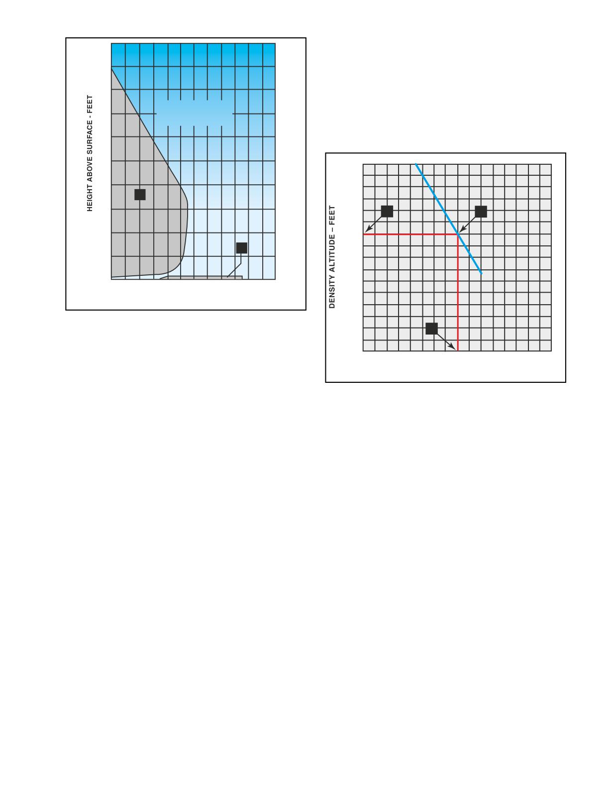
500
can be made. The time required, and therefore, altitude
necessary to attain a steady state autorotative descent,
450
is dependent on the weight of the helicopter and the
density altitude. For this reason, the H/V diagram for
400
some helicopter models is valid only when the helicop-
Smooth Hard Surface.
ter is operated in accordance with the gross weight vs.
350
Avoid Operation in
density altitude chart. Where appropriate, this chart is
Shaded Areas.
found in the rotorcraft flight manual for the particular
300
helicopter. [Figure 11-3]
250
7,000
200
A
150
6,000
A
B
100
B
50
5,000
0
0
10
20
30
40
50 60
70
80
90 100 110 120
INDICATED AIRSPEED KNOTS
(CORRECTED FOR INSTRUMENT ERROR)
4,000
Figure
11-2. By carefully studying the height/velocity
C
diagram, you will be able to avoid the combinations of alti-
tude and airspeed that may not allow you sufficient time or
3,000
altitude to enter a stabilized autorotative descent. You might
1,500
1,600
1,700
1,800
1,900
want to refer to this diagram during the remainder of the
GROSS WEIGHT - POUNDS
discussion on the height/velocity diagram.
Figure 11-3. Assuming a density altitude of 5,500 feet, the
height/velocity diagram in figure 11-2 would be valid up to a
gross weight of approximately 1,700 pounds. This is found by
You should avoid the low altitude, high airspeed portion
entering the graph at a density altitude of 5,500 feet (point A),
of the diagram (section B), because your recognition of an
then moving horizontally to the solid line (point B). Moving ver-
engine failure will most likely coincide with, or shortly
tically to the bottom of the graph (point C), you find that with the
occur after, ground contact. Even if you detect an engine
existing density altitude, the maximum gross weight under
failure, there may not be sufficient time to rotate the
which the height/velocity diagram is applicable is 1,700 pounds.
helicopter from a nose low, high airspeed attitude to one
suitable for slowing, then landing. Additionally, the
The gross weight vs. density altitude chart is not
altitude loss that occurs during recognition of engine fail-
intended as a restriction to gross weight, but as an advi-
ure and rotation to a landing attitude, may not leave
sory to the autorotative capability of the helicopter
enough altitude to prevent the tail skid from hitting the
during takeoff and climb. You must realize, however,
ground during the landing maneuver.
that at gross weights above those recommended by the
gross weight vs. density altitude chart, the H/V diagram
Basically, if the helicopter represented by this H/V dia-
is not restrictive enough.
gram is above 445 feet AGL, you have enough time and
altitude to enter a steady state autorotation, regardless
VORTEX RING STATE (SETTLING WITH
of your airspeed. If the helicopter is hovering at 5 feet
POWER)
AGL (or less) in normal conditions and the engine fails,
Vortex ring state describes an aerodynamic condition
a safe hovering autorotation can be made. Between
where a helicopter may be in a vertical descent with up
approximately 5 feet and 445 feet AGL, however, the
to maximum power applied, and little or no cyclic
transition to autorotation depends on the altitude and
authority. The term “settling with power” comes from
airspeed of the helicopter. Therefore, you should
the fact that helicopter keeps settling even though full
always be familiar with the height/velocity diagram for
engine power is applied.
the particular model of helicopter you are flying.
In a normal out-of-ground-effect hover, the helicopter
THE EFFECT OF WEIGHT VERSUS
is able to remain stationary by propelling a large mass
DENSITY ALTITUDE
of air down through the main rotor. Some of the air is
The height/velocity diagram depicts altitude and air-
recirculated near the tips of the blades, curling up from
speed situations from which a successful autorotation
the bottom of the rotor system and rejoining the air
11-5
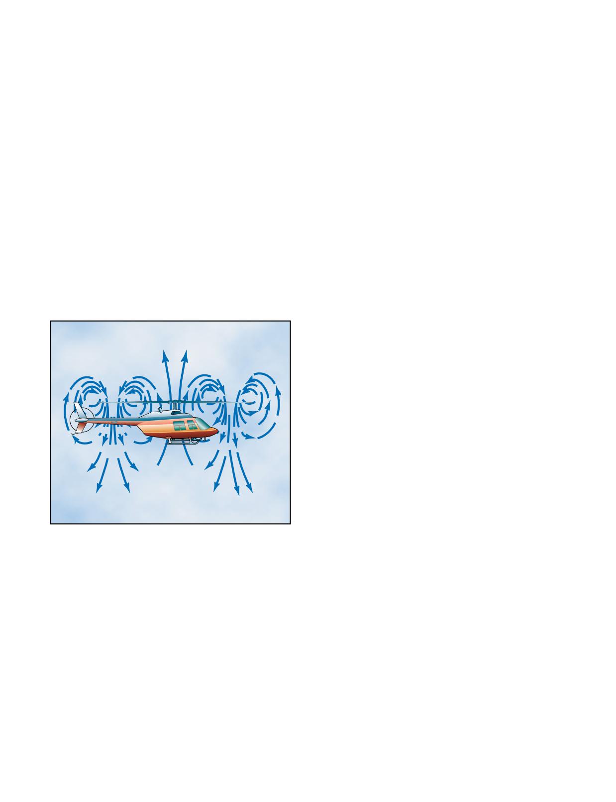
entering the rotor from the top. This phenomenon is
1.
A vertical or nearly vertical descent of at least
common to all airfoils and is known as tip vortices. Tip
300 feet per minute. (Actual critical rate depends
vortices consume engine power but produce no useful
on the gross weight, r.p.m., density altitude, and
lift. As long as the tip vortices are small, their only
other pertinent factors.)
effect is a small loss in rotor efficiency. However, when
the helicopter begins to descend vertically, it settles
2.
The rotor system must be using some of the avail-
into its own downwash, which greatly enlarges the tip
able engine power (from 20 to 100 percent).
vortices. In this vortex ring state, most of the power
developed by the engine is wasted in accelerating the
3.
The horizontal velocity must be slower than
air in a doughnut pattern around the rotor.
effective translational lift.
In addition, the helicopter may descend at a rate that
Some of the situations that are conducive to a settling
exceeds the normal downward induced-flow rate of the
with power condition are: attempting to hover out of
inner blade sections. As a result, the airflow of the inner
ground effect at altitudes above the hovering ceiling of
blade sections is upward relative to the disc. This pro-
the helicopter; attempting to hover out of ground effect
duces a secondary vortex ring in addition to the normal
without maintaining precise altitude control; or down-
tip-vortices. The secondary vortex ring is generated
wind and steep power approaches in which airspeed is
about the point on the blade where the airflow changes
permitted to drop to nearly zero.
from up to down. The result is an unsteady turbulent
flow over a large area of the disc. Rotor efficiency is
When recovering from a settling with power condition,
lost even though power is still being supplied from the
the tendency on the part of the pilot is to first try to stop
engine. [Figure 11-4]
the descent by increasing collective pitch. However,
this only results in increasing the stalled area of the
rotor, thus increasing the rate of descent. Since inboard
portions of the blades are stalled, cyclic control is
limited. Recovery is accomplished by increasing
forward speed, and/or partially lowering collective
pitch. In a fully developed vortex ring state, the only
recovery may be to enter autorotation to break the
vortex ring state. When cyclic authority is regained,
you can then increase forward airspeed.
For settling with power demonstrations and training in
recognition of vortex ring state conditions, all maneu-
vers should be performed at an elevation of at least
1,500 feet AGL.
To enter the maneuver, reduce power below hover
power. Hold altitude with aft cyclic until the
airspeed approaches 20 knots. Then allow the sink
Figure 11-4. Vortex ring state.
rate to increase to 300 feet per minute or more as the
attitude is adjusted to obtain an airspeed of less than
10 knots. When the aircraft begins to shudder, the
A fully developed vortex ring state is characterized by
application of additional up collective increases the
an unstable condition where the helicopter experiences
vibration and sink rate.
uncommanded pitch and roll oscillations, has little or
no cyclic authority, and achieves a descent rate, which,
Recovery should be initiated at the first sign of vor-
if allowed to develop, may approach 6,000 feet per
tex ring state by applying forward cyclic to increase
minute. It is accompanied by increased levels of
airspeed and simultaneously reducing collective.
vibration.
The recovery is complete when the aircraft passes
through effective translational lift and a normal
A vortex ring state may be entered during any maneu-
climb is established.
ver that places the main rotor in a condition of high
upflow and low forward airspeed. This condition is
RETREATING BLADE STALL
sometimes seen during quick-stop type maneuvers or
In forward flight, the relative airflow through the
during recoveries from autorotations. The following
main rotor disc is different on the advancing and
combination of conditions are likely to cause settling in
retreating side. The relative airflow over the advanc-
a vortex ring state:
ing side is higher due to the forward speed of the
11-6
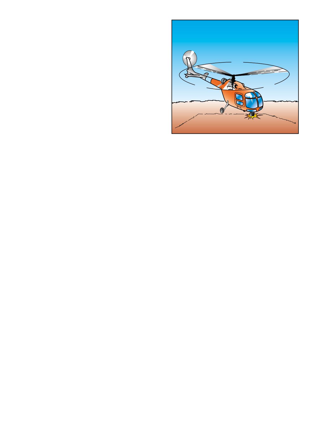
helicopter, while the relative airflow on the retreat-
ing side is lower. This dissymmetry of lift increases
as forward speed increases.
To generate the same amount of lift across the rotor
disc, the advancing blade flaps up while the retreat-
122°
ing blade flaps down. This causes the angle of attack
to decrease on the advancing blade, which reduces
lift, and increase on the retreating blade, which
increases lift. As the forward speed increases, at
122°
116°
some point the low blade speed on the retreating
blade, together with its high angle of attack, causes a
loss of lift (stall).
Retreating blade stall is a major factor in limiting a
helicopter’s top forward speed (VNE) and can be felt
developing by a low frequency vibration, pitching
up of the nose, and a roll in the direction of the
Figure 11-5. Hard contact with the ground can send a shock
retreating blade. High weight, low rotor r.p.m., high
wave to the main rotor head, resulting in the blades of a
density altitude, turbulence and/or steep, abrupt
three-bladed rotor system moving from their normal 120°
turns are all conducive to retreating blade stall at
relationship to each other. This could result in something like
high forward airspeeds. As altitude is increased,
122°, 122°, and 116° between blades. When one of the other
higher blade angles are required to maintain lift at a
landing gear strikes the surface, the unbalanced condition
could be further aggravated.
given airspeed. Thus, retreating blade stall is
encountered at a lower forward airspeed at altitude.
If the r.p.m. is low, the corrective action to stop ground
Most manufacturers publish charts and graphs show-
resonance is to close the throttle immediately and fully
ing a VNE decrease with altitude.
lower the collective to place the blades in low pitch. If the
r.p.m. is in the normal operating range, you should fly the
When recovering from a retreating blade stall condi-
helicopter off the ground, and allow the blades to auto-
tion, moving the cyclic aft only worsens the stall
matically realign themselves. You can then make a normal
as aft cyclic produces a flare effect, thus increasing
touchdown. If you lift off and allow the helicopter to
angles of attack. Pushing forward on the cyclic
firmly re-contact the surface before the blades are
also deepens the stall as the angle of attack on the
realigned, a second shock could move the blades again
retreating blade is increased. Correct recovery from
and aggravate the already unbalanced condition. This
retreating blade stall requires the collective to be
could lead to a violent, uncontrollable oscillation.
lowered first, which reduces blade angles and thus
angle of attack. Aft cyclic can then be used to slow
This situation does not occur in rigid or semirigid rotor
the helicopter.
systems, because there is no drag hinge. In addition,
skid type landing gear are not as prone to ground
GROUND RESONANCE
resonance as wheel type gear.
Ground resonance is an aerodynamic phenomenon
associated with fully-articulated rotor systems. It
DYNAMIC ROLLOVER
develops when the rotor blades move out of phase
A helicopter is susceptible to a lateral rolling tendency,
with each other and cause the rotor disc to become
called dynamic rollover, when lifting off the surface.
unbalanced. This condition can cause a helicopter to
For dynamic rollover to occur, some factor has to first
self-destruct in a matter of seconds. However, for
cause the helicopter to roll or pivot around a skid, or
this condition to occur, the helicopter must be in
landing gear wheel, until its critical rollover angle is
contact with the ground.
reached. Then, beyond this point, main rotor thrust con-
tinues the roll and recovery is impossible. If the critical
If you allow your helicopter to touch down firmly on
rollover angle is exceeded, the helicopter rolls on its
one corner (wheel type landing gear is most
side regardless of the cyclic corrections made.
conducive for this) the shock is transmitted to the
main rotor system. This may cause the blades to
Dynamic rollover begins when the helicopter starts to
move out of their normal relationship with each
pivot around its skid or wheel. This can occur for a
other. This movement occurs along the drag hinge.
variety of reasons, including the failure to remove a
[Figure 11-5]
tiedown or skid securing device, or if the skid or wheel
11-7
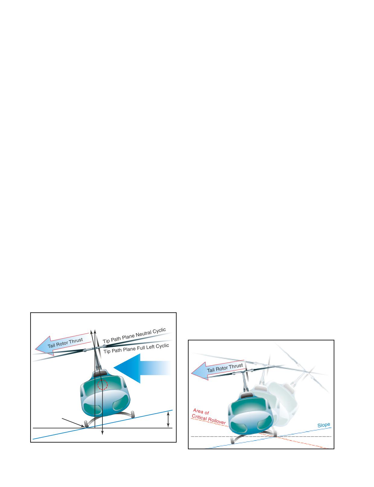
contacts a fixed object while hovering sideward, or if
3.
crosswinds from the left.
the gear is stuck in ice, soft asphalt, or mud. Dynamic
4.
left yaw inputs.
rollover may also occur if you do not use the proper
landing or takeoff technique or while performing slope
For helicopters with clockwise rotor rotation, the oppo-
operations. Whatever the cause, if the gear or skid
site would be true.
becomes a pivot point, dynamic rollover is possible if
you do not use the proper corrective technique.
CYCLIC TRIM
When maneuvering with one skid or wheel on the
Once started, dynamic rollover cannot be stopped by
ground, care must be taken to keep the helicopter cyclic
application of opposite cyclic control alone. For exam-
control properly trimmed. For example, if a slow take-
ple, the right skid contacts an object and becomes the
off is attempted and the cyclic is not positioned and
pivot point while the helicopter starts rolling to the
trimmed to account for translating tendency, the critical
right. Even with full left cyclic applied, the main rotor
recovery angle may be exceeded in less than two sec-
thrust vector and its moment follows the aircraft as it
onds. Control can be maintained if you maintain proper
continues rolling to the right. Quickly applying down
cyclic position and trim, and not allow the helicopter’s
collective is the most effective way to stop dynamic
roll and pitch rates to become too great. You should fly
rollover from developing. Dynamic rollover can occur
your helicopter into the air smoothly while keeping
in both skid and wheel equipped helicopters, and all
movements of pitch, roll, and yaw small, and not allow
types of rotor systems.
any untrimmed cyclic pressures.
CRITICAL CONDITIONS
NORMAL TAKEOFFS AND LANDINGS
Certain conditions reduce the critical rollover angle,
Dynamic rollover is possible even during normal take-
thus increasing the possibility for dynamic rollover and
offs and landings on relative level ground, if one wheel
reducing the chance for recovery. The rate of rolling
or skid is on the ground and thrust (lift) is approxi-
motion is also a consideration, because as the roll rate
mately equal to the weight of the helicopter. If the
increases, the critical rollover angle at which recovery
takeoff or landing is not performed properly, a roll rate
is still possible, is reduced. Other critical conditions
could develop around the wheel or skid that is on the
include operating at high gross weights with thrust (lift)
ground. When taking off or landing, perform the
approximately equal to the weight.
maneuver smoothly and trim the cyclic so that no pitch
or roll movement rates build up, especially the roll rate.
Refer to figure 11-6. The following conditions are
If the bank angle starts to increase to an angle of
most critical for helicopters with counter-clockwise
approximately 5 to 8°, and full corrective cyclic does
rotor rotation:
not reduce the angle, the collective should be reduced
to diminish the unstable rolling condition.
1.
right side skid/wheel down, since translating ten-
dency adds to the rollover force.
SLOPE TAKEOFFS AND LANDINGS
2.
right lateral center of gravity.
During slope operations, excessive application of cyclic
control into the slope, together with excessive collective
Main
pitch control, can result in the downslope skid rising
Rotor
sufficiently to exceed lateral cyclic control limits, and an
Thrust
upslope rolling motion can occur. [Figure 11-7]
Full Opposite Cyclic Limit
to Prevent Rolling Motion
Crosswind
Pivot Point
Bank Angle
Horizontal
Weight
Figure 11-6. Forces acting on a helicopter with right skid on
the ground.
Figure 11-7. Upslope rolling motion.
11-8
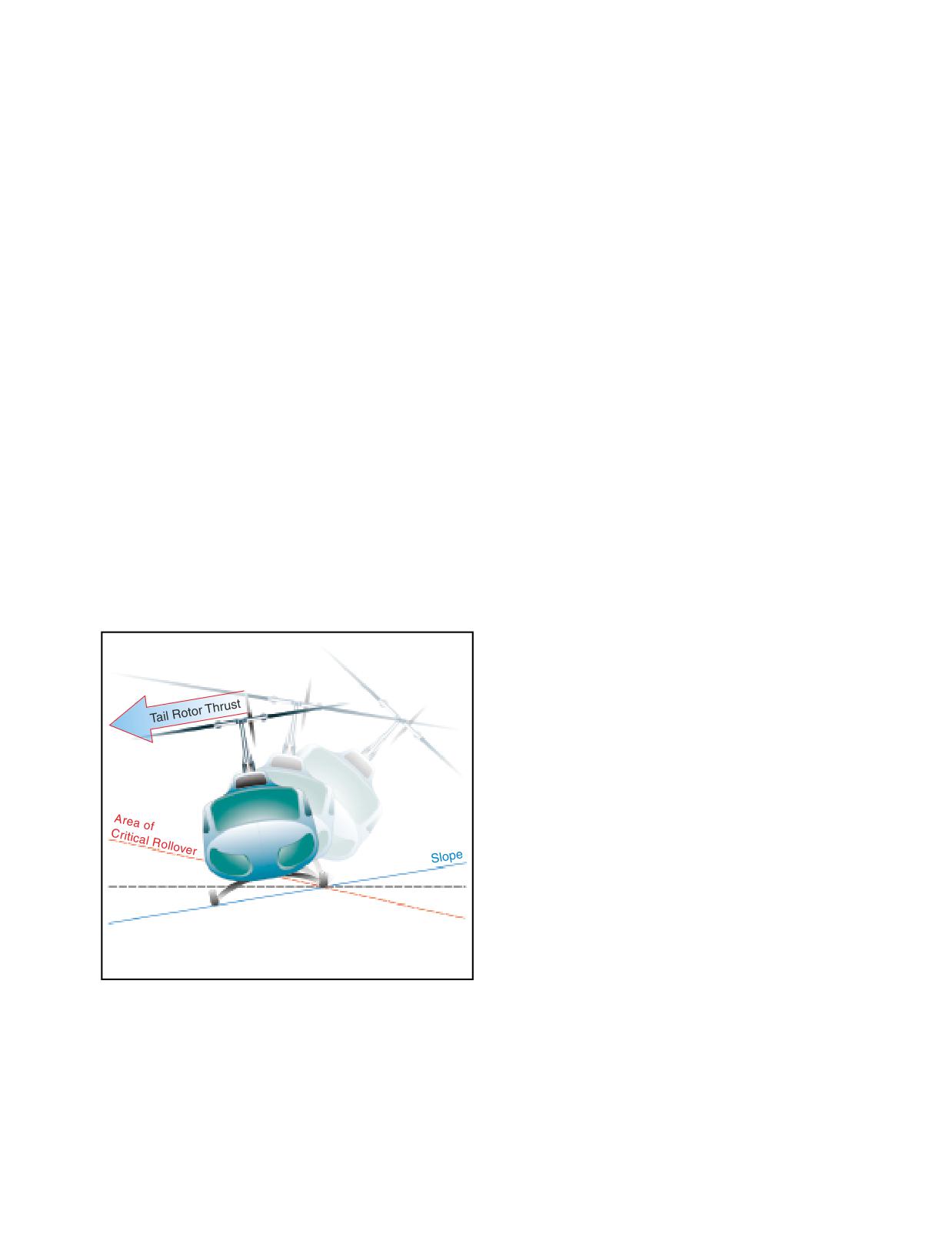
When performing slope takeoff and landing maneu-
develops a roll rate with one skid/wheel on the ground,
vers, follow the published procedures and keep the roll
the helicopter can roll over on its side.
rates small. Slowly raise the downslope skid or wheel
to bring the helicopter level, and then lift off. During
PRECAUTIONS
landing, first touch down on the upslope skid or wheel,
then slowly lower the downslope skid or wheel using
The following lists several areas to help you avoid
combined movements of cyclic and collective. If the
dynamic rollover.
helicopter rolls approximately 5 to 8° to the upslope
side, decrease collective to correct the bank angle and
1.
Always practice hovering autorotations into the
return to level attitude, then start the landing procedure
wind, but never when the wind is gusty or over
again.
10 knots.
2.
When hovering close to fences, sprinklers,
USE OF COLLECTIVE
bushes, runway/taxi lights, or other obstacles that
The collective is more effective in controlling the rolling
could catch a skid, use extreme caution.
motion than lateral cyclic, because it reduces the main
rotor thrust (lift). A smooth, moderate collective reduc-
3.
Always use a two-step liftoff. Pull in just enough
tion, at a rate less than approximately full up to full down
collective pitch control to be light on the skids
in two seconds, is adequate to stop the rolling motion.
and feel for equilibrium, then gently lift the
Take care, however, not to dump collective at too high a
helicopter into the air.
rate, as this may cause a main rotor blade to strike the
fuselage. Additionally, if the helicopter is on a slope and
4.
When practicing hovering maneuvers close to
the roll starts to the upslope side, reducing collective too
the ground, make sure you hover high enough to
fast may create a high roll rate in the opposite direction.
have adequate skid clearance with any obsta-
When the upslope skid/wheel hits the ground, the
cles, especially when practicing sideways or
dynamics of the motion can cause the helicopter to
rearward flight.
bounce off the upslope skid/wheel, and the inertia can
cause the helicopter to roll about the downslope ground
5.
When the wind is coming from the upslope direc-
contact point and over on its side. [Figure 11-8]
tion, less lateral cyclic control will be available.
6.
Tailwind conditions should be avoided when
Full Opposite Cyclic Limit
conducting slope operations.
to Prevent Rolling Motion
7.
When the left skid/wheel is upslope, less lateral
cyclic control is available due to the translating
tendency of the tail rotor. (This is true for
counter-rotating rotor systems)
8.
If passengers or cargo are loaded or unloaded, the
lateral cyclic requirement changes.
9.
If the helicopter utilizes interconnecting fuel lines
that allow fuel to automatically transfer from one
Horizontal
side of the helicopter to the other, the gravitational
flow of fuel to the downslope tank could change
the center of gravity, resulting in a different
amount of cyclic control application to obtain the
same lateral result.
Figure 11-8. Downslope rolling motion.
10.
Do not allow the cyclic limits to be reached. If the
cyclic control limit is reached, further lowering of
the collective may cause mast bumping. If this
The collective should not be pulled suddenly to get air-
occurs, return to a hover and select a landing point
borne, as a large and abrupt rolling moment in the
with a lesser degree of slope.
opposite direction could occur. Excessive application
of collective can result in the upslope skid rising suffi-
11.
During a takeoff from a slope, if the upslope
ciently to exceed lateral cyclic control limits. This
skid/wheel starts to leave the ground before the
movement may be uncontrollable. If the helicopter
downslope skid/wheel, smoothly and gently
11-9
lower the collective and check to see if the
turbulence, slow your forward airspeed and make small
downslope skid/wheel is caught on something.
control inputs. If turbulence becomes excessive,
Under these conditions vertical ascent is the only
consider making a precautionary landing. To help pre-
acceptable method of liftoff.
vent turbulence induced inputs, make sure your cyclic
arm is properly supported. One way to accomplish this
12. During flight operations on a floating platform, if
is to brace your arm against your leg. Even if you are
the platform is pitching/rolling while attempting to
not in turbulent conditions, you should avoid abrupt
land or takeoff, the result could be dynamic rollover.
movement of the cyclic and collective.
If you do find yourself in a low G condition, which
LOW G CONDITIONS AND MAST
can be recognized by a feeling of weightlessness
BUMPING
and an uncontrolled roll to the right, you should imme-
For cyclic control, small helicopters depend primarily
diately and smoothly apply aft cyclic. Do not attempt
on tilting the main rotor thrust vector to produce
to correct the rolling action with lateral cyclic. By
control moments about the aircraft center of gravity
applying aft cyclic, you will load the rotor system,
(CG), causing the helicopter to roll or pitch in the
which in turn produces thrust. Once thrust is restored,
desired direction. Pushing the cyclic control forward
left cyclic control becomes effective, and you can roll
abruptly from either straight-and-level flight or after a
the helicopter to a level attitude.
climb can put the helicopter into a low G (weightless)
flight condition. In forward flight, when a push-over is
LOW ROTOR RPM AND BLADE STALL
performed, the angle of attack and thrust of the rotor is
As mentioned earlier, low rotor r.p.m. during an
reduced, causing a low G or weightless flight condi-
autorotation might result in a less than successful
tion. During the low G condition, the lateral cyclic has
maneuver. However, if you let rotor r.p.m. decay to the
little, if any, effect because the rotor thrust has been
point where all the rotor blades stall, the result is usu-
reduced. Also, in a counter-clockwise rotor system (a
ally fatal, especially when it occurs at altitude. The
clockwise system would be the reverse), there is no
danger of low rotor r.p.m. and blade stall is greatest in
main rotor thrust component to the left to counteract
small helicopters with low blade inertia. It can occur
the tail rotor thrust to the right, and since the tail rotor
in a number of ways, such as simply rolling the throt-
is above the CG, the tail rotor thrust causes the helicop-
tle the wrong way, pulling more collective pitch than
ter to roll rapidly to the right, If you attempt to stop the
power available, or when operating at a high density
right roll by applying full left cyclic before regaining
altitude.
main rotor thrust, the rotor can exceed its flapping
limits and cause structural failure of the rotor shaft due
to mast bumping, or it may allow a blade to contact the
When the rotor r.p.m. drops, the blades try to maintain
airframe. [Figure 11-9]
the same amount of lift by increasing pitch. As the
pitch increases, drag increases, which requires more
power to keep the blades turning at the proper r.p.m.
When power is no longer available to maintain r.p.m.,
and therefore lift, the helicopter begins to descend.
This changes the relative wind and further increases
the angle of attack. At some point the blades will stall
unless r.p.m. is restored. If all blades stall, it is almost
impossible to get smooth air flowing across the
blades.
Even though there is a safety factor built into most hel-
icopters, anytime your rotor r.p.m. falls below the green
Figure 11-9. In a low G condition, improper corrective action
arc, and you have power, simultaneously add throttle
could lead to the main rotor hub contacting the rotor mast.
The contact with the mast becomes more violent with each
and lower the collective. If you are in forward flight,
successive flapping motion. This, in turn, creates a greater
gently applying aft cyclic loads up the rotor system and
flapping displacement. The result could be a severely
helps increase rotor r.p.m. If you are without power,
damaged rotor mast, or the main rotor system could sepa-
immediately lower the collective and apply aft cyclic.
rate from the helicopter.
RECOVERY FROM LOW ROTOR RPM
Since a low G condition could have disastrous results,
Under certain conditions of high weight, high tempera-
the best way to prevent it from happening is to avoid the
ture, or high density altitude, you might get into a
conditions where it might occur. This means avoiding
situation where the r.p.m. is low even though you are
turbulence as much as possible. If you do encounter
using maximum throttle. This is usually the result of
11-10
the main rotor blades having an angle of attack that has
results in a severe yawing to the right. At low power
created so much drag that engine power is not suffi-
settings and high airspeeds, the yaw is less severe. High
cient to maintain or attain normal operating r.p.m.
airspeeds tend to streamline the helicopter and keep it
from spinning.
If you are in a low r.p.m. situation, the lifting power of
the main rotor blades can be greatly diminished. As soon
If a tail rotor failure occurs, power has to be reduced in
order to reduce main rotor torque. The techniques
as you detect a low r.p.m. condition, immediately apply
differ depending on whether the helicopter is in flight
additional throttle, if available, while slightly lowering
or in a hover, but will ultimately require an autorotation.
the collective. This reduces main rotor pitch and drag. As
If a complete tail rotor failure occurs while hovering,
the helicopter begins to settle, smoothly raise the collec-
enter a hovering autorotation by rolling off the
tive to stop the descent. At hovering altitude you may
throttle. If the failure occurs in forward flight,
have to repeat this technique several times to regain nor-
enter a normal autorotation by lowering the collective
mal operating r.p.m. This technique is sometimes called
and rolling off the throttle. If the helicopter has
“milking the collective.” When operating at altitude, the
enough forward airspeed (close to cruising speed) when
collective may have to be lowered only once to regain
the failure occurs, and depending on the helicopter
rotor speed. The amount the collective can be lowered
design, the vertical stabilizer may provide enough direc-
depends on altitude. When hovering near the surface,
tional control to allow you to maneuver the helicopter to
make sure the helicopter does not contact the ground as
a more desirable landing sight. Some of the yaw may be
the collective is lowered.
compensated for by applying slight cyclic control oppo-
site the direction of yaw. This helps in directional
Since the tail rotor is geared to the main rotor, low main
control, but also increases drag. Care must be taken not
rotor r.p.m. may prevent the tail rotor from producing
to lose too much forward airspeed because the stream-
enough thrust to maintain directional control. If pedal
lining effect diminishes as airspeed is reduced. Also,
control is lost and the altitude is low enough that a
more altitude is required to accelerate to the
landing can be accomplished before the turning rate
correct airspeed if an autorotation is entered into at a
increases dangerously, slowly decrease collective pitch,
low airspeed.
maintain a level attitude with cyclic control, and land.
A mechanical control failure limits or prevents con-
SYSTEM MALFUNCTIONS
trol of tail rotor thrust and is usually caused by a
The reliability and dependability record of modern
stuck or broken control rod or cable. While the tail
helicopters is very impressive. By following the
rotor is still producing antitorque thrust, it cannot be
manufacturer’s recommendations regarding periodic
controlled by the pilot. The amount of antitorque
maintenance and inspections, you can eliminate most
depends on the position where the controls jam or
systems and equipment failures. Most malfunctions or
fail. Once again, the techniques differ depending on
failures can be traced to some error on the part of the
the amount of tail rotor thrust, but an autorotation is
pilot; therefore, most emergencies can be averted before
generally not required.
they happen. An actual emergency is a rare occurrence.
LANDING-STUCK LEFT PEDAL
ANTITORQUE SYSTEM FAILURE
Be sure to follow the procedures and techniques
Antitorque failures usually fall into two categories.
outlined in the FAA-approved rotorcraft flight man-
One focuses on failure of the power drive portion of the
ual for the helicopter you are flying. A stuck left
tail rotor system resulting in a complete loss of anti-
pedal, such as might be experienced during takeoff or
torque. The other category covers mechanical control
climb conditions, results in the helicopter’s nose
failures where the pilot is unable to change or control
yawing to the left when power is reduced. Rolling off
tail rotor thrust even though the tail rotor may still be
the throttle and entering an autorotation only makes
providing antitorque thrust.
matters worse. The landing profile for a stuck left
pedal is best described as a normal approach to a
Tail rotor drive system failures include driveshaft fail-
momentary hover at three to four feet above the
ures, tail rotor gearbox failures, or a complete loss of
surface. Following an analysis, make the landing. If
the tail rotor itself. In any of these cases, the loss of
the helicopter is not turning, simply lower the
antitorque normally results in an immediate yawing of
helicopter to the surface. If the helicopter is turning
the helicopter’s nose. The helicopter yaws to the right
to the right, roll the throttle toward flight idle the
in a counter-clockwise rotor system and to the left in a
amount necessary to stop the turn as you land. If the
clockwise system. This discussion assumes a
helicopter is beginning to turn left, you should be
helicopter with a counter-clockwise rotor system. The
able to make the landing prior to the turn rate
severity of the yaw is proportionate to the amount of
becoming excessive. However, if the turn rate
power being used and the airspeed. An antitorque
becomes excessive prior to the landing, simply
failure with a high power setting at a low airspeed
execute a takeoff and return for another landing.
11-11
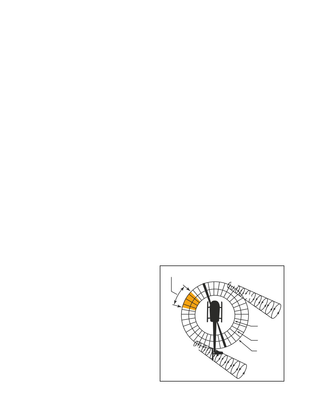
LANDING-STUCK NEUTRAL OR RIGHT PEDAL
have identified three relative wind azimuth regions that
The landing profile for a stuck neutral or a stuck right
can either singularly, or in combination, create an LTE
pedal is a low power approach or descent with a
conducive environment. These regions can overlap,
running or roll-on landing. The approach profile can
and thrust variations may be more pronounced. Also,
best be described as a steep approach with a flare at the
flight testing has determined that the tail rotor does not
bottom to slow the helicopter. The power should be low
actually stall during the period. When operating in
enough to establish a left yaw during the descent. The
these areas at less than 30 knots, pilot workload
left yaw allows a margin of safety due to the fact that
increases dramatically.
the helicopter will turn to the right when power is
applied. This allows the momentary use of power at the
MAIN ROTOR DISC INTERFERENCE
(285-315°)
bottom of the approach. As you apply power, the heli-
Refer to figure 11-10. Winds at velocities of 10 to 30
copter rotates to the right and becomes aligned with the
knots from the left front cause the main rotor
landing area. At this point, roll the throttle to flight idle
vortex to be blown into the tail rotor by the relative
and make the landing. The momentary use of power
wind. The effect of this main rotor disc vortex causes
helps stop the descent and allows additional time for
the tail rotor to operated in an extremely turbulent envi-
you to level the helicopter prior to closing the throttle.
ronment. During a right turn, the tail rotor experiences
a reduction of thrust as it comes into the area of the
If the helicopter is not yawed to the left at the conclusion
main rotor disc vortex. The reduction in tail rotor thrust
of the flare, roll the throttle to flight idle and use the
comes from the airflow changes experienced at the tail
collective to cushion the touchdown. As with any
rotor as the main rotor disc vortex moves across the tail
running or roll-on landing, use the cyclic to maintain the
rotor disc. The effect of the main rotor disc vortex
ground track. This technique results in a longer ground
initially increases the angle of attack of the tail rotor
run or roll than if the helicopter was yawed to the left.
blades, thus increasing tail rotor thrust. The increase in
the angle of attack requires that right pedal pressure be
UNANTICIPATED YAW / LOSS OF TAIL
ROTOR EFFECTIVENESS (LTE)
added to reduce tail rotor thrust in order to maintain the
Unanticipated yaw is the occurrence of an uncom-
same rate of turn. As the main rotor vortex passes the
manded yaw rate that does not subside of its own
tail rotor, the tail rotor angle of attack is reduced. The
accord and, which, if not corrected, can result in the
reduction in the angle of attack causes a reduction in
loss of helicopter control. This uncommanded yaw rate
thrust and a right yaw acceleration begins. This accel-
is referred to as loss of tail rotor effectiveness (LTE)
eration can be surprising, since you were previously
and occurs to the right in helicopters with a counter-
adding right pedal to maintain the right turn rate. This
clockwise rotating main rotor and to the left in helicop-
thrust reduction occurs suddenly, and if uncorrected,
ters with a clockwise main rotor rotation. Again, this
develops into an uncontrollable rapid rotation about the
discussion covers a helicopter with a counter-clockwise
mast. When operating within this region, be aware that
rotor system and an antitorque rotor.
the reduction in tail rotor thrust can happen quite
suddenly, and be prepared to react quickly to counter
LTE is not related to an equipment or maintenance mal-
this reduction with additional left pedal input.
function and may occur in all single-rotor helicopters
Region of Disc
at airspeeds less than 30 knots. It is the result of the tail
Vortex Interference
360°
rotor not providing adequate thrust to maintain direc-
0°
tional control, and is usually caused by either certain
315°
330°
30°
wind azimuths (directions) while hovering, or by an
insufficient tail rotor thrust for a given power setting at
60°
300°
higher altitudes.
285°
270°
90°
For any given main rotor torque setting in perfectly
steady air, there is an exact amount of tail rotor thrust
10 Knots
required to prevent the helicopter from yawing either
240°
120°
left or right. This is known as tail rotor trim thrust. In
15 Knots
order to maintain a constant heading while hovering,
you should maintain tail rotor thrust equal to trim thrust.
210°
150°
20 Knots
The required tail rotor thrust is modified by the effects
of the wind. The wind can cause an uncommanded yaw
by changing tail rotor effective thrust. Certain relative
wind directions are more likely to cause tail rotor thrust
variations than others. Flight and wind tunnel tests
Figure 11-10. Main rotor disc vortex interference.
11-12
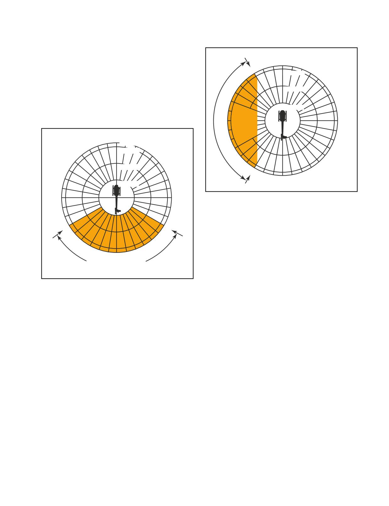
WEATHERCOCK STABILITY
accelerates the right turn rate. Pilot workload during a
(120-240°)
tail rotor vortex ring state is high. Do not allow a right
In this region, the helicopter attempts to weathervane
yaw rate to increase.
its nose into the relative wind. [Figure 11-11] Unless a
360°
resisting pedal input is made, the helicopter starts a
0°
17 Knots
slow, uncommanded turn either to the right or left
330°
30°
15 Knots
depending upon the wind direction. If the pilot allows a
right yaw rate to develop and the tail of the helicopter
moves into this region, the yaw rate can accelerate
300°
10 Knots
60°
rapidly. In order to avoid the onset of LTE in this
downwind condition, it is imperative to maintain posi-
5 Knots
Region of
tive control of the yaw rate and devote full attention to
Roughness
flying the helicopter.
270°
90°
Due toTail
Rotor Vortex
360°
Ring State
0°
17 Knots
330°
30°
15 Knots
240°
120°
10 Knots
300°
60°
150°
210°
180°
5 Knots
270°
90°
Figure 11-12. Tail rotor vortex ring state.
LTE AT ALTITUDE
At higher altitudes, where the air is thinner, tail rotor
240°
120°
thrust and efficiency is reduced. When operating at
high altitudes and high gross weights, especially while
hovering, the tail rotor thrust may not be sufficient to
210°
150°
maintain directional control and LTE can occur. In this
180°
case, the hovering ceiling is limited by tail rotor thrust
Region Where Weathercock
and not necessarily power available. In these condi-
Stability Can Introduce Yaw Rates
tions gross weights need to be reduced and/or
Figure 11-11. Weathercock stability.
operations need to be limited to lower density altitudes.
TAIL ROTOR VORTEX RING STATE
REDUCING THE ONSET OF LTE
(210-330°)
To help reduce the onset of loss of tail rotor effective-
Winds within this region cause a tail rotor vortex ring
ness, there are some steps you can follow.
state to develop. [Figure 11-12] The result is a non-uni-
form, unsteady flow into the tail rotor. The vortex ring
1.
Maintain maximum power-on rotor r.p.m. If the
state causes tail rotor thrust variations, which result in
main rotor r.p.m. is allowed to decrease, the anti-
yaw deviations. The net effect of the unsteady flow is
torque thrust available is decreased proportionally.
an oscillation of tail rotor thrust. Rapid and continuous
pedal movements are necessary to compensate for the
2.
Avoid tailwinds below an airspeed of 30 knots. If
rapid changes in tail rotor thrust when hovering in a left
loss of translational lift occurs, it results in an
crosswind. Maintaining a precise heading in this region
increased power demand and additional anti-
is difficult, but this characteristic presents no signifi-
torque pressures.
cant problem unless corrective action is delayed.
However, high pedal workload, lack of concentration
3.
Avoid out of ground effect (OGE) operations and
and overcontrolling can all lead to LTE.
high power demand situations below an airspeed
of 30 knots.
When the tail rotor thrust being generated is less than
the thrust required, the helicopter yaws to the right.
4.
Be especially aware of wind direction and velocity
When hovering in left crosswinds, you must concen-
when hovering in winds of about 8-12 knots. There
trated on smooth pedal coordination and not allow an
are no strong indicators that translational lift has
uncontrolled right yaw to develop. If a right yaw rate
been reduced. A loss of translational lift results in
is allowed to build, the helicopter can rotate into the
an unexpected high power demand and an
wind azimuth region where weathercock stability then
increased antitorque requirement.
11-13
5.
Be aware that if a considerable amount of left
although it is left on under normal conditions. A
pedal is being maintained, a sufficient amount of
pressure indicator in the cockpit may be installed to
left pedal may not be available to counteract an
monitor the system.
unanticipated right yaw.
An impending hydraulic failure can be recognized by a
6.
Be alert to changing wind conditions, which may
grinding or howling noise from the pump or actuators,
be experienced when flying along ridge lines and
increased control forces and feedback, and limited
around buildings.
control movement. The corrective action required is
stated in detail in the appropriate rotorcraft flight
RECOVERY TECHNIQUE
manual. However, in most cases, airspeed needs to be
If a sudden unanticipated right yaw occurs, the follow-
reduced in order to reduce control forces. The hydraulic
ing recovery technique should be performed. Apply full
switch and circuit breaker should be checked and
left pedal while simultaneously moving cyclic control
recycled. If hydraulic power is not restored, make a
forward to increase speed. If altitude permits, reduce
shallow approach to a running or roll-on landing. This
power. As recovery is effected, adjust controls for
technique is used because it requires less control force
normal forward flight.
and pilot workload. Additionally, the hydraulic system
should be disabled, by either pulling the circuit breaker
Collective pitch reduction aids in arresting the yaw rate
and/or placing the switch in the off position. The
but may cause an excessive rate of descent. Any large,
reason for this is to prevent an inadvertent restoration
rapid increase in collective to prevent ground or
of hydraulic power, which may lead to overcontrolling
obstacle contact may further increase the yaw rate and
near the ground.
decrease rotor r.p.m. The decision to reduce collective
must be based on your assessment of the altitude
In those helicopters where the control forces are so
available for recovery.
high that they cannot be moved without hydraulic
assistance, two or more independent hydraulic systems
If the rotation cannot be stopped and ground contact is
may be installed. Some helicopters use hydraulic accu-
imminent, an autorotation may be the best course of
mulators to store pressure that can be used for a short
action. Maintain full left pedal until the rotation stops,
time while in an emergency if the hydraulic pump fails.
then adjust to maintain heading.
This gives you enough time to land the helicopter with
normal control.
MAIN DRIVE SHAFT FAILURE
The main drive shaft, located between the engine and
GOVERNOR FAILURE
the main rotor gearbox, transmits engine power to the
Governors automatically adjust engine power to main-
main rotor gearbox. In some helicopters, particularly
tain rotor r.p.m. when the collective pitch is changed. If
those with piston engines, a drive belt is used instead of
the governor fails, any change in collective pitch
a drive shaft. A failure of the drive shaft or belt has the
requires you to manually adjust the throttle to maintain
same effect as an engine failure, because power is no
correct r.p.m. In the event of a high side governor
longer provided to the main rotor, and an autorotation
failure, the engine and rotor r.p.m. try to increase above
has to be initiated. There are a few differences,
the normal range. If the r.p.m. cannot be reduced and
however, that need to be taken into consideration. If the
controlled with the throttle, close the throttle and enter
drive shaft or belt breaks, the lack of any load on the
an autorotation. If the governor fails on the low side,
engine results in an overspeed. In this case, the throttle
normal r.p.m. may not be attainable, even if the throttle
must be closed in order to prevent any further damage.
is manually controlled. In this case, the collective has
In some helicopters, the tail rotor drive system
to be lowered to maintain r.p.m. A running or roll-on
continues to be powered by the engine even if the main
landing may be performed if the engine can maintain
drive shaft breaks. In this case, when the engine
sufficient rotor r.p.m. If there is insufficient power,
unloads, a tail rotor overspeed can result. If this hap-
enter an autorotation.
pens, close the throttle immediately and enter an
autorotation.
ABNORMAL VIBRATIONS
With the many rotating parts found in helicopters, some
HYDRAULIC FAILURES
vibration is inherent. You need to understand the cause
Most helicopters, other than smaller piston powered
and effect of helicopter vibrations because abnormal
helicopters, incorporate the use of hydraulic actuators
vibrations cause premature component wear and may
to overcome high control forces. A hydraulic system
even result in structural failure. With experience, you
consists of actuators, also called servos, on each flight
learn what vibrations are normal versus those that are
control; a pump, which is usually driven by the main
abnormal and can then decide whether continued flight
rotor gearbox; and a reservoir to store the hydraulic
is safe or not. Helicopter vibrations are categorized into
fluid. A switch in the cockpit can turn the system off,
low, medium, or high frequency.
11-14
LOW FREQUENCY VIBRATIONS
Computing course, time, speed, and distance informa-
Low frequency vibrations (100-500 cycles per minute)
tion in flight requires the same computations used
usually originate from the main rotor system. The
during preflight planning. However, because of the
vibration may be felt through the controls, the airframe,
limited cockpit space, and because you must divide
or a combination of both. Furthermore, the vibration
your attention between flying the helicopter, making
may have a definite direction of push or thrust. It may
calculations, and scanning for other aircraft, you should
be vertical, lateral, horizontal, or even a combination.
take advantage of all possible shortcuts and rule-of-
Normally, the direction of the vibration can be deter-
thumb computations.
mined by concentrating on the feel of the vibration,
which may push you up and down, backwards and
When in flight, it is rarely practical to actually plot a
forwards, or from side to side. The direction of the
course on a sectional chart and mark checkpoints and
vibration and whether it is felt in the controls or the
distances. Furthermore, because an alternate airport is
airframe is an important means for the mechanic
usually not very far from your original course, actual
to troubleshoot the source. Some possible causes
plotting is seldom necessary.
could be that the main rotor blades are out of track or
balance, damaged blades, worn bearings, dampers out
A course to an alternate can be measured accurately
of adjustment, or worn parts.
with a protractor or plotter, but can also be measured
with reasonable accuracy using a straightedge and the
MEDIUM AND HIGH FREQUENCY VIBRATIONS
compass rose depicted around VOR stations. This
Medium frequency vibrations (1,000 - 2,000 cycles per
approximation can be made on the basis of a radial
minute) and high frequency vibrations (2,000 cycles
from a nearby VOR or an airway that closely parallels
per minute or higher) are normally associated with out-
the course to your alternate. However, you must
of-balance components that rotate at a high r.p.m., such
remember that the magnetic heading associated with
as the tail rotor, engine, cooling fans, and components
a VOR radial or printed airway is outbound from
of the drive train, including transmissions, drive shafts,
the station. To find the course TO the station, it may
bearings, pulleys, and belts. Most tail rotor vibrations
be necessary to determine the reciprocal of the
can be felt through the tail rotor pedals as long as there
indicated heading.
are no hydraulic actuators, which usually dampen out
the vibration. Any imbalance in the tail rotor system is
Distances can be determined by using a plotter, or by
very harmful, as it can cause cracks to develop and
placing a finger or piece of paper between the two and
rivets to work loose. Piston engines usually produce a
then measuring the approximate distance on the
normal amount of high frequency vibration, which is
mileage scale at the bottom of the chart.
aggravated by engine malfunctions such as spark plug
fouling, incorrect magneto timing, carburetor icing
Before changing course to proceed to an alternate, you
and/or incorrect fuel/air mixture. Vibrations in turbine
should first consider the relative distance and route of
engines are often difficult to detect as these engines
flight to all suitable alternates. In addition, you should
operate at a very high r.p.m.
consider the type of terrain along the route. If circum-
TRACKING AND BALANCE
stances warrant, and your helicopter is equipped with
Modern equipment used for tracking and balancing the
navigational equipment, it is typically easier to navi-
main and tail rotor blades can also be used to detect
gate to an alternate airport that has a VOR or NDB
other vibrations in the helicopter. These systems use
facility on the field.
accelerometers mounted around the helicopter to detect
the direction, frequency, and intensity of the vibration.
After you select the most appropriate alternate, approx-
The built-in software can then analyze the information,
imate the magnetic course to the alternate using
pinpoint the origin of the vibration, and suggest the
a compass rose or airway on the sectional chart. If time
corrective action.
permits, try to start the diversion over a prominent
ground feature. However, in an emergency, divert
FLIGHT DIVERSION
promptly toward your alternate. To complete all
There will probably come a time in your flight career
plotting, measuring, and computations involved before
when you will not be able to make it to your destination.
diverting to the alternate may only aggravate an
This can be the result of unpredictable weather conditions,
actual emergency.
a system malfunction, or poor preflight planning. In any
case, you will need to be able to safely and efficiently
Once established on course, note the time, and then
divert to an alternate destination. Before any cross-
use the winds aloft nearest to your diversion point to
country flight, check the charts for airports or suitable
calculate a heading and groundspeed. Once you have
landing areas along or near your route of flight. Also,
calculated your groundspeed, determine a new arrival
check for navaids that can be used during a diversion.
time and fuel consumption.
11-15
You must give priority to flying the helicopter while
ries for each person on board, and it should be
dividing your attention between navigation and
stored in a sealed waterproof container. It should
planning. When determining an altitude to use while
have been inspected by the pilot or his represen-
diverting, you should consider cloud heights, winds,
tative within the previous six months, and bear a
terrain, and radio reception.
label verifying the amount and satisfactory con-
dition of the contents.
LOST PROCEDURES
•
A supply of water.
Getting lost in an aircraft is a potentially dangerous
situation especially when low on fuel. Helicopters have
•
Cooking utensils.
an advantage over airplanes, as they can land almost
anywhere before they run out of fuel.
•
Matches in a waterproof container.
•
A portable compass.
If you are lost, there are some good common sense
procedures to follow. If you are nowhere near or cannot
•
An ax at least 2.5 pounds with a handle not less
see a town or city, the first thing you should do is climb.
than 28 inches in length.
An increase in altitude increases radio and navigation
reception range, and also increases radar coverage. If
•
A flexible saw blade or equivalent cutting tool.
you are flying near a town or city, you may be able to
read the name of the town on a water tower or even land
•
30 feet of snare wire and instructions for use.
to ask directions.
•
Fishing equipment, including still-fishing bait
and gill net with not more than a two inch mesh.
If your helicopter has a navigational radio, such as a
VOR or ADF receiver, you can possibly determine
•
Mosquito nets or netting and insect repellent
your position by plotting your azimuth from two or
sufficient to meet the needs of all persons aboard,
more navigational facilities. If GPS is installed, or you
when operating in areas where insects are likely
have a portable aviation GPS on board, you can use it
to be hazardous.
to determine your position and the location of the
nearest airport.
•
A signaling mirror.
Communicate with any available facility using
•
At least three pyrotechnic distress signals.
frequencies shown on the sectional chart. If you are
•
A sharp, quality jackknife or hunting knife.
able to communicate with a controller, you may be
offered radar vectors. Other facilities may offer
•
A suitable survival instruction manual.
direction finding (DF) assistance. To use this
procedure, the controller will request you to hold
•
Flashlight with spare bulbs and batteries.
down your transmit button for a few seconds and
then release it. The controller may ask you to change
•
Portable ELT with spare batteries.
directions a few times and repeat the transmit
procedure. This gives the controller enough infor-
Additional items when there are no trees:
mation to plot your position and then give you vec-
tors to a suitable landing sight. If your situation
• Stove with fuel or a self-contained means of pro-
becomes threatening, you can transmit your prob-
viding heat for cooking.
lems on the emergency frequency 121.5 MHZ and
• Tent(s) to accommodate everyone on board.
set your transponder to 7700. Most facilities, and
even airliners, monitor the emergency frequency.
Additional items for winter operations:
EMERGENCY EQUIPMENT AND
• Winter sleeping bags for all persons when the
SURVIVAL GEAR
temperature is expected to be below 7°C.
Both Canada and Alaska require pilots to carry survival
gear. However, it is good common sense that any time
• Two pairs of snow shoes.
you are flying over rugged and desolated terrain, con-
• Spare ax handle.
sider carrying survival gear. Depending on the size and
storage capacity of your helicopter, the following are
• Honing stone or file.
some suggested items:
• Ice chisel.
• Food that is not subject to deterioration due to
heat or cold. There should be at least 10,000 calo-
• Snow knife or saw knife.
11-16
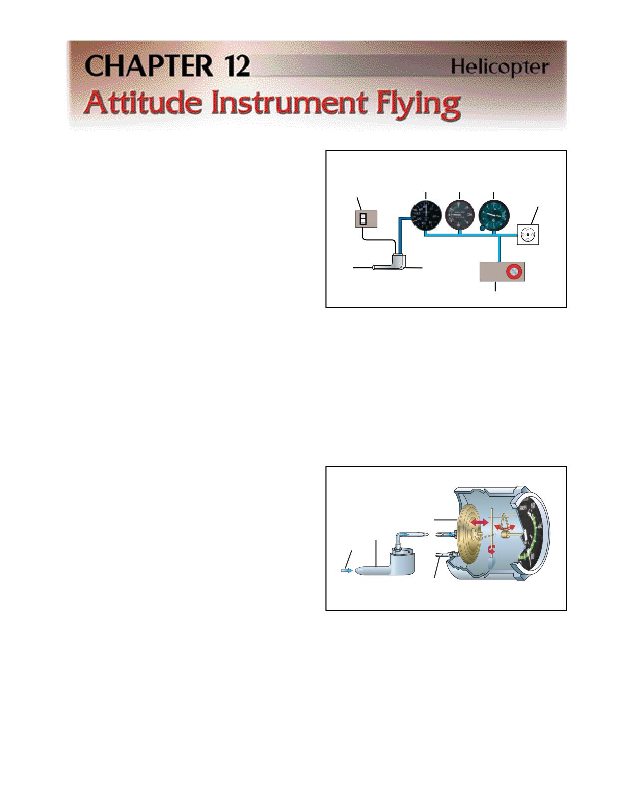
Attitude instrument flying in helicopters is essentially
Vertical
visual flying with the flight instruments substituted for
Speed
the various reference points on the helicopter and the
Airspeed
Indicator
Pitot
Indicator
(VSI)
Altimeter
natural horizon. Control changes, required to produce a
Heater Switch
Static Port
given attitude by reference to instruments, are identical
ON
to those used in helicopter VFR flight, and your
OFF
thought processes are the same. Basic instrument train-
ing is intended as a building block towards attaining an
instrument rating. It will also enable you to do a 180°
Pitot
Drain
ALT
turn in case of inadvertent incursion into instrument
Tube
STATIC AIR
Opening
PULL ON
meteorological conditions (IMC).
Alternate Static Source
FLIGHT INSTRUMENTS
Figure 12-1. Ram air pressure is supplied only to the airspeed
When flying a helicopter with reference to the flight
indicator, while static pressure is used by all three instru-
instruments, proper instrument interpretation is the
ments. Electrical heating elements may be installed to pre-
vent ice from forming on the pitot tube. A drain opening to
basis for aircraft control. Your skill, in part, depends on
remove moisture is normally included.
your understanding of how a particular instrument or
system functions, including its indications and limita-
tions. With this knowledge, you can quickly determine
what an instrument is telling you and translate that
tion is needed is that an airspeed indicator and aircraft
information into a control response.
performance are affected equally by changes in air den-
sity. An indicated airspeed always yields the same
performance because the indicator has, in fact, com-
PITOT-STATIC INSTRUMENTS
pensated for the change in the environment.
The pitot-static instruments, which include the airspeed
indicator, altimeter, and vertical speed indicator, oper-
ate on the principle of differential air pressure. Pitot
pressure, also called impact, ram, or dynamic pressure,
is directed only to the airspeed indicator, while static
pressure, or ambient pressure, is directed to all three
Diaphragm
instruments. An alternate static source may be included
Pitot Tube
allowing you to select an alternate source of ambient
Ram Air
pressure in the event the main port becomes blocked.
[Figure 12-1]
Static Air Line
AIRSPEED INDICATOR
The airspeed indicator displays the speed of the heli-
Figure 12-2. Ram air pressure from the pitot tube is directed
copter through the air by comparing ram air pressure
to a diaphragm inside the airspeed indicator. The airtight
from the pitot tube with static air pressure from the
case is vented to the static port. As the diaphragm expands
static port-the greater the differential, the greater the
or contracts, a mechanical linkage moves the needle on the
speed. The instrument displays the result of this pres-
face of the indicator.
sure differential as indicated airspeed (IAS).
Manufacturers use this speed as the basis for determin-
ing helicopter performance, and it may be displayed in
INSTRUMENT CHECK-During the preflight, ensure
knots, miles per hour, or both. [Figure 12-2] When an
that the pitot tube, drain hole, and static ports are unob-
indicated airspeed is given for a particular situation,
structed. Before liftoff, make sure the airspeed indicator
you normally use that speed without making a correc-
is reading zero. If there is a strong wind blowing directly
tion for altitude or temperature. The reason no correc-
at the helicopter, the airspeed indicator may read higher
12-1
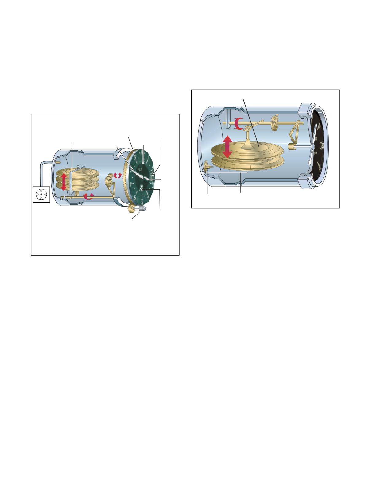
than zero, depending on the wind speed and direction.
VERTICAL SPEED INDICATOR
As you begin your takeoff, make sure the airspeed indi-
The vertical speed indicator (VSI) displays the rate of
cator is increasing at an appropriate rate. Keep in mind,
climb or descent in feet per minute (f.p.m.) by measur-
however, that the airspeed indication might be unreli-
ing how fast the ambient air pressure increases or
able below a certain airspeed due to rotor downwash.
decreases as the helicopter changes altitude. Since the
VSI measures only the rate at which air pressure
ALTIMETER
changes, air temperature has no effect on this instru-
The altimeter displays altitude in feet by sensing pres-
ment. [Figure 12-4]
sure changes in the atmosphere. There is an adjustable
barometric scale to compensate for changes in atmos-
Diaphragm
pheric pressure. [Figure 12-3]
Altitude
Indication
Altimeter
Aneroid
Scale
Setting Window
Wafers
10,000 ft
100 ft Pointer
Pointer
1,000 ft
Pointer
Direct Static
Calibrated
Pressure
Leak
Static Port
Crosshatch
Figure 12-4. Although the sealed case and diaphragm are
Altimeter Setting
Flag
Adjustment Knob
both connected to the static port, the air inside the case is
A crosshatched
area appears
restricted through a calibrated leak. When the pressures are
on some altimeters
equal, the needle reads zero. As you climb or descend, the
when displaying
an altitude below
pressure inside the diaphragm instantly changes, and the
10,000 feet MSL.
needle registers a change in vertical direction. When the
pressure differential stabilizes at a definite ratio, the needle
registers the rate of altitude change.
Figure 12-3. The main component of the altimeter is a stack of
sealed aneroid wafers. They expand and contract as atmos-
pheric pressure from the static source changes. The mechani-
cal linkage translates these changes into pointer movements on
There is a lag associated with the reading on the VSI,
the indicator.
and it may take a few seconds to stabilize when show-
ing rate of climb or descent. Rough control technique
and turbulence can further extend the lag period and
The basis for altimeter calibration is the International
cause erratic and unstable rate indications. Some air-
Standard Atmosphere (ISA), where pressure, tempera-
craft are equipped with an instantaneous vertical speed
ture, and lapse rates have standard values. However,
indicator (IVSI), which incorporates accelerometers to
actual atmospheric conditions seldom match the stan-
compensate for the lag found in the typical VSI.
dard values. In addition, local pressure readings within
a given area normally change over a period of time, and
INSTRUMENT CHECK-During the preflight, ensure
pressure frequently changes as you fly from one area to
that the static ports are unobstructed. Check to see that
another. As a result, altimeter indications are subject to
the VSI is indicating zero before lift-off. During takeoff,
errors, the extent of which depends on how much the
check for a positive rate of climb indication.
pressure, temperature, and lapse rates deviate from stan-
dard, as well as how recently you have set the altimeter.
SYSTEM ERRORS
The best way to minimize altimeter errors is to update
The pitot-static system and associated instruments are
the altimeter setting frequently. In most cases, use the
usually very reliable. Errors are generally caused when
current altimeter setting of the nearest reporting station
the pitot or static openings are blocked. This may be
along your route of flight per regulatory requirements.
caused by dirt, ice formation, or insects. Check the pitot
and static openings for obstructions during the preflight.
INSTRUMENT CHECK-During the preflight, ensure
It is also advisable to place covers on the pitot and static
that the static ports are unobstructed. Before lift-off, set
ports when the helicopter is parked on the ground.
the altimeter to the current setting. If the altimeter indi-
cates within 75 feet of the actual elevation, the altimeter
The airspeed indicator is the only instrument affected by a
is generally considered acceptable for use.
blocked pitot tube. The system can become clogged in two
12-2
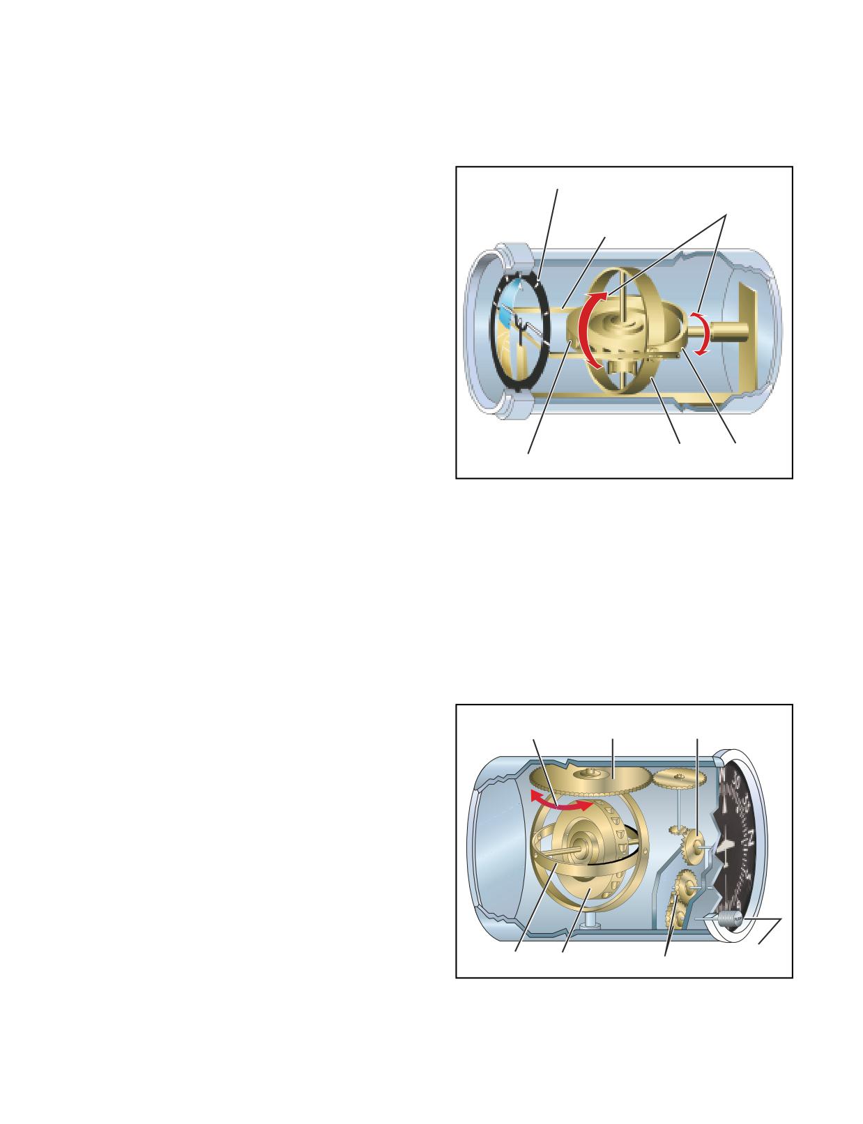
ways. If the ram air inlet is clogged, but the drain hole
installed in helicopters are electrically powered, there
remains open, the airspeed indicator registers zero, regard-
may be a separate power switch, as well as a warning
less of airspeed. If both the ram air inlet and the drain hole
flag within the instrument, that indicates a loss of
become blocked, pressure in the line is trapped, and the
power. A caging or “quick erect” knob may be
airspeed indicator reacts like an altimeter, showing an
included, so you can stabilize the spin axis if the gyro
increase in airspeed with an increase in altitude, and a
has tumbled. [Figure 12-5]
decrease in speed as altitude decreases. This occurs as
long as the static port remains unobstructed.
Bank Index
Gimbal
Horizon
Rotation
Reference
If the static port alone becomes blocked, the airspeed
Arm
indicator continues to function, but with incorrect read-
ings. When you are operating above the altitude where
the static port became clogged, the airspeed indicator
reads lower than it should. Conversely, when operating
below that altitude, the indicator reads higher than the
correct value. The amount of error is proportional to
the distance from the altitude where the static system
became blocked. The greater the difference, the greater
the error. With a blocked static system, the altimeter
freezes at the last altitude and the VSI freezes at zero.
Both instruments are then unusable.
Some helicopters are equipped with an alternate static
Pitch
Roll
Gyro
Gimbal
Gimbal
source, which may be selected in the event that the main
static system becomes blocked. The alternate source gen-
Figure 12-5. The gyro in the attitude indicator spins in the
erally vents into the cabin, where air pressures are slightly
horizontal plane. Two mountings, or gimbals, are used so
different than outside pressures, so the airspeed and
that both pitch and roll can be sensed simultaneously. Due to
altimeter usually read higher than normal. Correction
rigidity in space, the gyro remains in a fixed position relative
to the horizon as the case and helicopter rotate around it.
charts may be supplied in the flight manual.
HEADING INDICATOR
GYROSCOPIC INSTRUMENTS
The heading indicator, which is sometimes referred to
The three gyroscopic instruments that are required for
as a directional gyro (DG), senses movement around
instrument flight are the attitude indicator, heading
the vertical axis and provides a more accurate heading
indicator, and turn indicator. When installed in helicop-
reference compared to a magnetic compass, which has
ters, these instruments are usually electrically powered.
a number of turning errors. [Figure 12-6].
Gyros are affected by two principles-rigidity in space and
Gimbal
Main
Compass
precession. Rigidity in space means that once a gyro is
Rotation
Drive Gear
Card Gear
spinning, it tends to remain in a fixed position and resists
external forces applied to it. This principle allows a gyro to
be used to measure changes in attitude or direction.
Precession is the tilting or turning of a gyro in response to
pressure. The reaction to this pressure does not occur at
the point where it was applied; rather, it occurs at a point
that is 90° later in the direction of rotation from where the
pressure was applied. This principle allows the gyro to
determine a rate of turn by sensing the amount of pres-
sure created by a change in direction. Precession can also
create some minor errors in some instruments.
Adjustment
Gimbal
Gyro
Adjustment Gears
Knob
ATTITUDE INDICATOR
Figure 12-6. A heading indicator displays headings based on
The attitude indicator provides a substitute for the nat-
a 360° azimuth, with the final zero omitted. For example, a 6
ural horizon. It is the only instrument that provides an
represents 060°, while a 21 indicates 210°. The adjustment
immediate and direct indication of the helicopter’s
knob is used to align the heading indicator with the magnetic
pitch and bank attitude. Since most attitude indicators
compass.
12-3
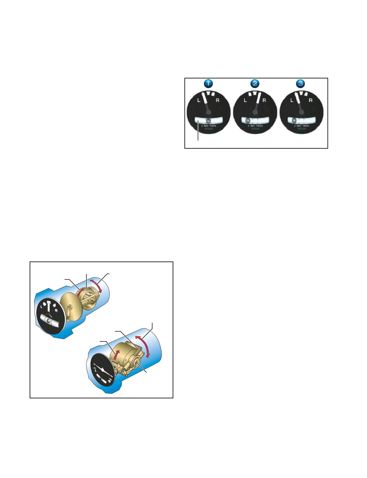
Due to internal friction within the gyroscope, preces-
Another part of both the turn coordinator and the turn-
sion is common in heading indicators. Precession
and-slip indicator is the inclinometer. The position of
causes the selected heading to drift from the set value.
the ball defines whether the turn is coordinated or not.
Some heading indicators receive a magnetic north ref-
The helicopter is either slipping or skidding anytime
erence from a remote source and generally need no
the ball is not centered, and usually requires an adjust-
adjustment. Heading indicators that do not have this
ment of the antitorque pedals or angle of bank to cor-
automatic north-seeking capability are often called
rect it. [Figure 12-8]
“free” gyros, and require that you periodically adjust
them. You should align the heading indicator with the
magnetic compass before flight and check it at 15-
minute intervals during flight. When you do an in-flight
alignment, be certain you are in straight-and-level,
unaccelerated flight, with the magnetic compass show-
ing a steady indication.
TURN INDICATORS
Turn indicators show the direction and the rate of turn.
Inclinometer
A standard rate turn is 3° per second, and at this rate
Figure 12-8. In a coordinated turn (instrument 1), the ball is
you will complete a 360° turn in two minutes. A half-
centered. In a skid (instrument 2), the rate of turn is too great
standard rate turn is 1.5° per second. Two types of
for the angle of bank, and the ball moves to the outside of the
indicators are used to display this information. The
turn. Conversely, in a slip (instrument 3), the rate of turn is
too small for the angle of bank, and the ball moves to the
turn-and-slip indicator uses a needle to indicate direc-
inside of the turn.
tion and turn rate. When the needle is aligned with the
white markings, called the turn index, you are in a
standard rate turn. A half-standard rate turn is indi-
INSTRUMENT CHECK-During your preflight, check
cated when the needle is halfway between the indexes.
to see that the inclinometer is full of fluid and has no
The turn-and-slip indicator does not indicate roll rate.
air bubbles. The ball should also be resting at its lowest
The turn coordinator is similar to the turn-and-slip
point. Since almost all gyroscopic instruments installed
indicator, but the gyro is canted, which allows it to
in a helicopter are electrically driven, check to see that
sense roll rate in addition to rate of turn. The turn coor-
the power indicators are displaying off indications.
dinator uses a miniature aircraft to indicate direction,
Turn the master switch on and listen to the gyros spool
as well as the turn and roll rate. [Figure 12-7]
up. There should be no abnormal sounds, such as a
Horizontal
grinding sound, and the power out indicator flags
Gyro
Gimbal
should not be displayed. After engine start and before
Gyro
Rotation
Rotation
liftoff, set the direction indicator to the magnetic com-
TURN-AND-SLIP
pass. During hover turns, check the heading indicator
INDICATOR
for proper operation and ensure that it has not pre-
cessed significantly. The turn indicator should also
indicate a turn in the correct direction. During takeoff,
Gimbal
check the attitude indicator for proper indication and
Rotation
recheck it during the first turn.
Gimbal
Gyro
MAGNETIC COMPASS
Rotation
In some helicopters, the magnetic compass is the only
direction seeking instrument. Although the compass
appears to move, it is actually mounted in such a way
that the helicopter turns about the compass card as the
TURN
card maintains its alignment with magnetic north.
Canted Gyro
COORDINATOR
COMPASS ERRORS
The magnetic compass can only give you reliable
directional information if you understand its limitations
Figure 12-7. The gyros in both the turn-and-slip indicator and
the turn coordinator are mounted so that they rotate in a verti-
and inherent errors. These include magnetic variation,
cal plane. The gimbal in the turn coordinator is set at an angle,
compass deviation, and magnetic dip.
or canted, which means precession allows the gyro to sense
both rate of roll and rate of turn. The gimbal in the turn-and-slip
MAGNETIC VARIATION
indicator is horizontal. In this case, precession allows the gyro
to sense only rate of turn. When the needle or miniature aircraft
When you fly under visual flight rules, you ordinar-
is aligned with the turn index, you are in a standard-rate turn.
ily navigate by referring to charts, which are oriented
12-4
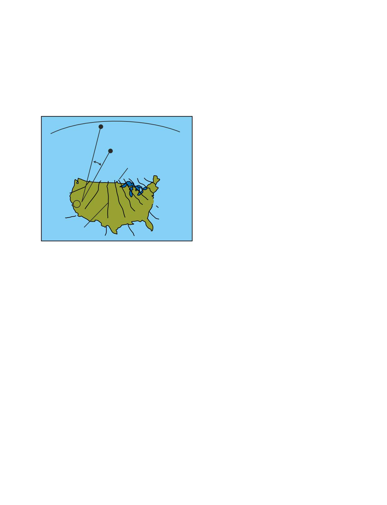
to true north. Because the aircraft compass is oriented
Magnetic dip is responsible for compass errors during
to magnetic north, you must make allowances for the
acceleration, deceleration, and turns.
difference between these poles in order to navigate
properly. You do this by applying a correction called
Acceleration and deceleration errors are fluctuations
variation to convert a true direction to a magnet direc-
in the compass during changes in speed. In the north-
tion. Variation at a given point is the angular differ-
ern hemisphere, the compass swings toward the north
ence between the true and magnetic poles. The amount
during acceleration and toward the south during decel-
of variation depends on where you are located on the
eration. When the speed stabilizes, the compass
earth’s surface. Isogonic lines connect points where
returns to an accurate indication. This error is most
the variation is equal, while the agonic line defines the
pronounced when you are flying on a heading of east
points where the variation is zero. [Figure 12-9]
or west, and decreases gradually as you fly closer to a
north or south heading. The error does not occur when
you are flying directly north or south. The memory
True
aid, ANDS (Accelerate North, Decelerate South) may
North Pole
help you recall this error. In the southern hemisphere,
Magnetic
this error occurs in the opposite direction.
North Pole
17°
Turning errors are most apparent when you are turning
Agonic
to or from a heading of north or south. This error
Line
increases as you near the poles as magnetic dip becomes
20°
more apparent. There is no turning error when flying
20°
near the magnetic equator. In the northern hemisphere,
15°
when you make a turn from a northerly heading, the
10°
A
5°
compass gives an initial indication of a turn in the
15°
0°
opposite direction. It then begins to show the turn in
10°
5°
the proper direction, but lags behind the actual head-
Isogonic Lines
ing. The amount of lag decreases as the turn continues,
then disappears as the helicopter reaches a heading of
east or west. When you make a turn from a southerly
Figure 12-9. Variation at point A in the western United States
is 17°. Since the magnetic north pole is located to the east of
heading, the compass gives an indication of a turn in
the true north pole in relation to this point, the variation is
the correct direction, but leads the actual heading. This
easterly. When the magnetic pole falls to the west of the true
error also disappears as the helicopter approaches an
north pole, variation is westerly.
east or west heading.
COMPASS DEVIATION
INSTRUMENT CHECK-Prior to flight, make sure that
Besides the magnetic fields generated by the earth, other
the compass is full of fluid. During hover turns, the
magnetic fields are produced by metal and electrical
compass should swing freely and indicate known head-
accessories within the helicopter. These magnetic fields
ings. Since that magnetic compass is required for all
distort the earth’s magnet force and cause the compass
flight operations, the aircraft should never be flown
to swing away from the correct heading. Manufacturers
with a faulty compass.
often install compensating magnets within the compass
housing to reduce the effects of deviation. These mag-
INSTRUMENT FLIGHT
nets are usually adjusted while the engine is running and
To achieve smooth, positive control of the helicopter
all electrical equipment is operating. Deviation error,
during instrument flight, you need to develop three
however, cannot be completely eliminated; therefore, a
fundamental skills. They are instrument cross-check,
compass correction card is mounted near the compass.
instrument interpretation, and aircraft control.
The compass correction card corrects for deviation that
occurs from one heading to the next as the lines of force
INSTRUMENT CROSS-CHECK
interact at different angles.
Cross-checking, sometimes referred to as scanning, is
the continuous and logical observation of instruments
MAGNETIC DIP
for attitude and performance information. In attitude
Magnetic dip is the result of the vertical component of
instrument flying, an attitude is maintained by reference
the earth’s magnetic field. This dip is virtually non-
to the instruments, which produces the desired result in
existent at the magnetic equator, since the lines of force
performance. Due to human error, instrument error, and
are parallel to the earth’s surface and the vertical com-
helicopter performance differences in various atmos-
ponent is minimal. As you move a compass toward the
pheric and loading conditions, it is difficult to
poles, the vertical component increases, and magnetic
establish an attitude and have performance remain
dip becomes more apparent at these higher latitudes.
constant for a long period of time. These variables make
12-5
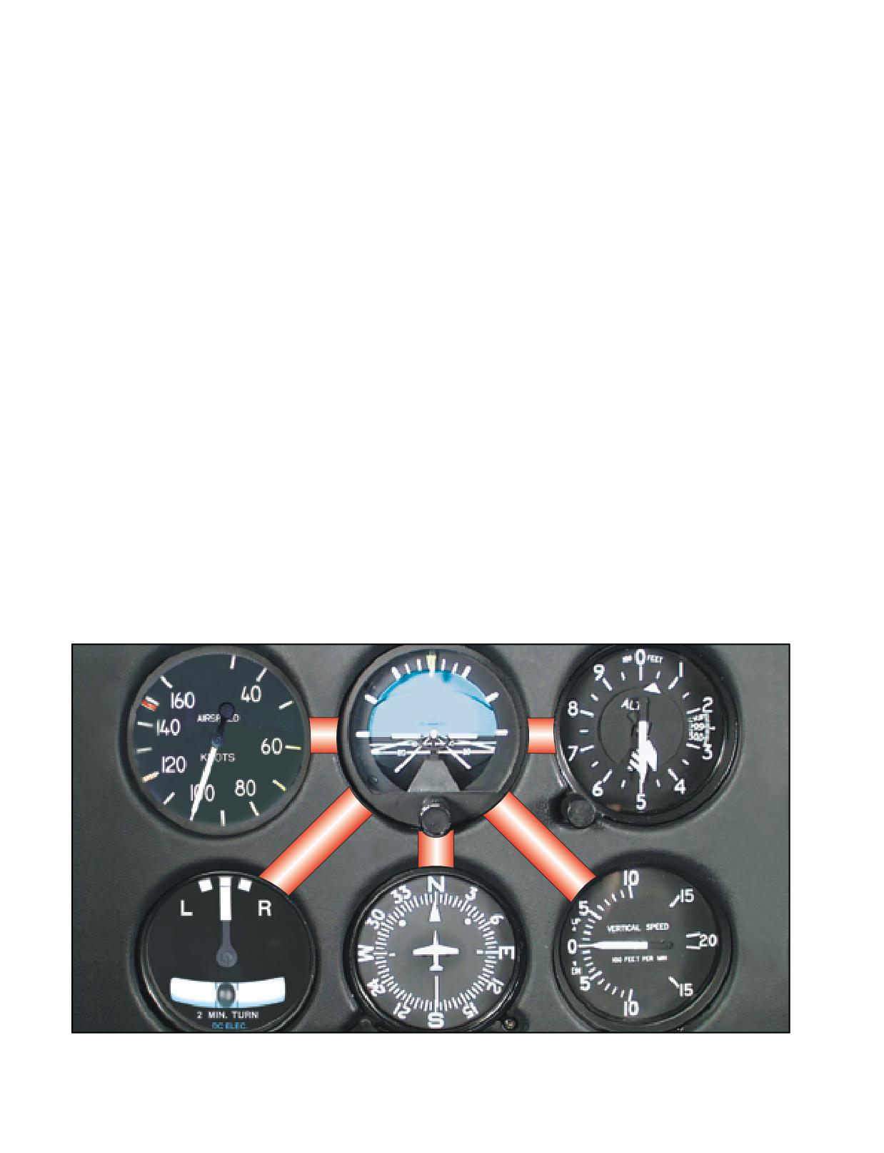
it necessary for you to constantly check the instruments
essary for helicopter performance information. This dif-
and make appropriate changes in the helicopter’s atti-
fers from fixation in that you are using other instruments,
tude. The actual technique may vary depending on what
but are giving too much attention to a particular one.
instruments are installed and where they are installed,
as well as your experience and proficiency level. For
During performance of a maneuver, you may sometimes
this discussion, we will concentrate on the six basic
fail to anticipate significant instrument indications fol-
flight instruments discussed earlier. [Figure 12-10]
lowing attitude changes. For example, during leveloff
from a climb or descent, you may concentrate on pitch
At first, you may have a tendency to cross-check
control, while forgetting about heading or roll informa-
rapidly, looking directly at the instruments without
tion. This error, called “omission,” results in erratic
knowing exactly what information you are seeking.
control of heading and bank.
However, with familiarity and practice, the instrument
cross-check reveals definite trends during specific
In spite of these common errors, most pilots can adapt
flight conditions. These trends help you control the
well to flight by instrument reference after instruction
helicopter as it makes a transition from one flight
and practice. You may find that you can control the hel-
condition to another.
icopter more easily and precisely by instruments.
If you apply your full concentration to a single instrument,
INSTRUMENT INTERPRETATION
you will encounter a problem called “fixation.” This results
The flight instruments together give a picture of what
from a natural human inclination to observe a specific
is going on. No one instrument is more important than
instrument carefully and accurately, often to the exclusion
the next; however, during certain maneuvers or condi-
of other instruments. Fixation on a single instrument usu-
tions, those instruments that provide the most pertinent
ally results in poor control. For example, while performing
and useful information are termed primary instruments.
a turn, you may have a tendency to watch only the turn-and-
Those which back up and supplement the primary
slip indicator instead of including other instruments in your
instruments are termed supporting instruments. For
cross-check. This fixation on the turn-and-slip indicator
example, since the attitude indicator is the only instru-
often leads to a loss of altitude through poor pitch and bank
ment that provides instant and direct aircraft attitude
control. You should look at each instrument only long
information, it should be considered primary during
enough to understand the information it presents, then con-
any change in pitch or bank attitude. After the new atti-
tinue on to the next one. Similarly, you may find yourself
tude is established, other instruments become primary,
placing too much “emphasis” on a single instrument,
and the attitude indicator usually becomes the support-
instead of relying on a combination of instruments nec-
ing instrument.
Figure 12-10. In most situations, the cross-check pattern includes the attitude indicator between the cross-check of each of the
other instruments. A typical cross-check might progress as follows: attitude indicator, altimeter, attitude indicator, VSI, attitude
indicator, heading indicator, attitude indicator, and so on.
12-6
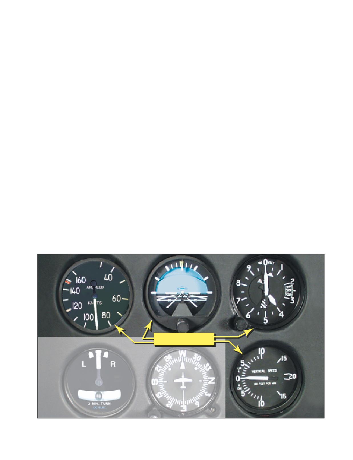
AIRCRAFT CONTROL
In order to fly a helicopter by reference to the
Controlling the helicopter is the result of accurately
instruments, you should know the approximate
interpreting the flight instruments and translating these
power settings required for your particular helicopter
readings into correct control responses. Aircraft control
in various load configurations and flight conditions.
involves adjustment to pitch, bank, power, and trim in
Trim, in helicopters, refers to the use of the cyclic center-
order to achieve a desired flight path.
ing button, if the helicopter is so equipped, to relieve all
possible cyclic pressures. Trim also refers to the use of
Pitch attitude control is controlling the movement of
pedal adjustment to center the ball of the turn indicator.
the helicopter about its lateral axis. After interpreting
Pedal trim is required during all power changes.
the helicopter’s pitch attitude by reference to the pitch
instruments (attitude indicator, altimeter, airspeed indi-
The proper adjustment of collective pitch and cyclic
cator, and vertical speed indicator), cyclic control
friction helps you relax during instrument flight.
adjustments are made to affect the desired pitch atti-
Friction should be adjusted to minimize overcontrol-
tude. In this chapter, the pitch attitudes illustrated are
ling and to prevent creeping, but not applied to such a
approximate and will vary with different helicopters.
degree that control movement is limited. In addition,
many helicopters equipped for instrument flight con-
Bank attitude control is controlling the angle made by
tain stability augmentation systems or an autopilot to
the lateral tilt of the rotor and the natural horizon, or,
help relieve pilot workload.
the movement of the helicopter about its longitudinal
STRAIGHT-AND-LEVEL FLIGHT
axis. After interpreting the helicopter’s bank instru-
Straight-and-level unaccelerated flight consists of
ments (attitude indicator, heading indicator, and turn
maintaining the desired altitude, heading, airspeed, and
indicator), cyclic control adjustments are made to attain
pedal trim.
the desired bank attitude.
PITCH CONTROL
Power control is the application of collective pitch with
The pitch attitude of a helicopter is the angular relation
corresponding throttle control, where applicable. In
of its longitudinal axis and the natural horizon. If avail-
straight-and-level flight, changes of collective pitch are
able, the attitude indicator is used to establish the
made to correct for altitude deviations if the error is
desired pitch attitude. In level flight, pitch attitude
more than 100 feet, or the airspeed is off by more than
varies with airspeed and center of gravity. At a constant
10 knots. If the error is less than that amount, use a
altitude and a stabilized airspeed, the pitch attitude is
slight cyclic climb or descent.
approximately level. [Figure 12-11]
PITCH CONTROL
Figure 12-11. The flight instruments for pitch control are the airspeed indicator, attitude indicator, altimeter, and vertical
speed indicator.
12-7
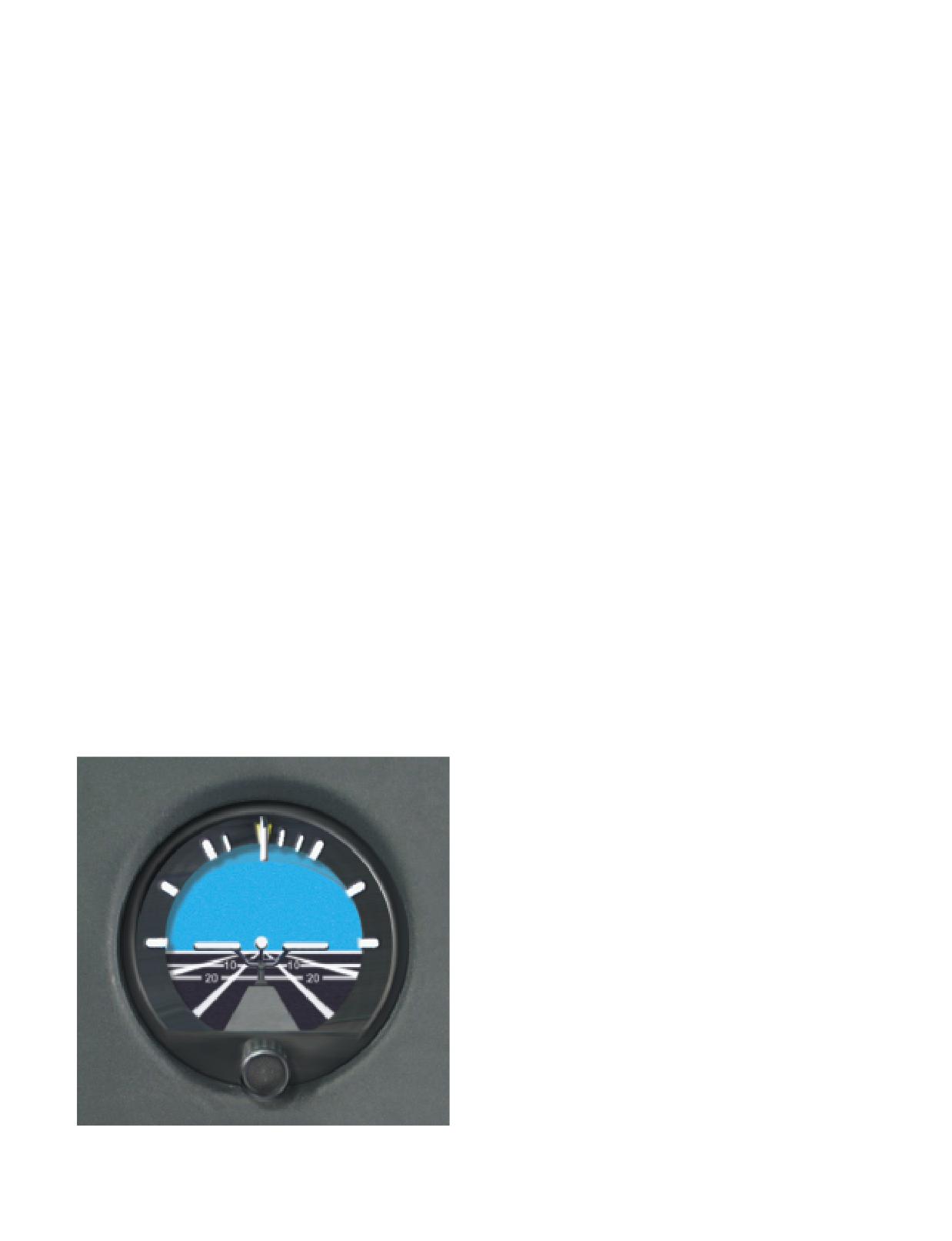
ATTITUDE INDICATOR
one-half bar correction is normally the maximum pitch
The attitude indicator gives a direct indication of the
attitude correction from level flight attitude. After you
pitch attitude of the helicopter. In visual flight, you
have made the correction, cross-check the other pitch
attain the desired pitch attitude by using the cyclic to
instruments to determine whether the pitch attitude
raise and lower the nose of the helicopter in relation to
change is sufficient. If more correction is needed to
the natural horizon. During instrument flight, you fol-
return to altitude, or if the airspeed varies more than 10
low exactly the same procedure in raising or lowering
knots from that desired, adjust the power.
the miniature aircraft in relation to the horizon bar.
ALTIMETER
You may note some delay between control application
The altimeter gives an indirect indication of the pitch
and resultant instrument change. This is the normal
attitude of the helicopter in straight-and-level flight.
control lag in the helicopter and should not be confused
Since the altitude should remain constant in level
with instrument lag. The attitude indicator may show
flight, deviation from the desired altitude shows a need
small misrepresentations of pitch attitude during
for a change in pitch attitude, and if necessary, power.
maneuvers involving acceleration, deceleration, or
When losing altitude, raise the pitch attitude and, if
turns. This precession error can be detected quickly by
necessary, add power. When gaining altitude, lower the
cross-checking the other pitch instruments.
pitch attitude and, if necessary, reduce power.
If the miniature aircraft is properly adjusted on the
The rate at which the altimeter moves helps in deter-
ground, it may not require readjustment in flight. If the
mining pitch attitude. A very slow movement of the
miniature aircraft is not on the horizon bar after level-
altimeter indicates a small deviation from the desired
off at normal cruising airspeed, adjust it as necessary
pitch attitude, while a fast movement of the altimeter
while maintaining level flight with the other pitch
indicates a large deviation from the desired pitch atti-
instruments. Once the miniature aircraft has been
tude. Make any corrective action promptly, with small
adjusted in level flight at normal cruising airspeed,
control changes. Also, remember that movement of the
leave it unchanged so it will give an accurate picture of
altimeter should always be corrected by two distinct
pitch attitude at all times.
changes. The first is a change of attitude to stop the
altimeter; and the second, a change of attitude to
When making initial pitch attitude corrections to main-
return smoothly to the desired altitude. If the altitude
tain altitude, the changes of attitude should be small
and airspeed are more than 100 feet and 10 knots low,
and smoothly applied. The initial movement of the
respectively, apply power along with an increase of
horizon bar should not exceed one bar width high or
pitch attitude. If the altitude and airspeed are high by
low. [Figure 12-12] If a further change is required, an
more than 100 feet and 10 knots, reduce power and
additional correction of one-half bar normally corrects
lower the pitch attitude.
any deviation from the desired altitude. This one and
There is a small lag in the movement of the altimeter;
however, for all practical purposes, consider that the
altimeter gives an immediate indication of a change, or
a need for change in pitch attitude.
Since the altimeter provides the most pertinent infor-
mation regarding pitch in level flight, it is considered
primary for pitch.
VERTICAL SPEED INDICATOR
The vertical speed indicator gives an indirect indication
of the pitch attitude of the helicopter and should be used
in conjunction with the other pitch instruments to attain
a high degree of accuracy and precision. The instrument
indicates zero when in level flight. Any movement of
the needle from the zero position shows a need for an
immediate change in pitch attitude to return it to zero.
Always use the vertical speed indicator in conjunction
with the altimeter in level flight. If a movement of the
vertical speed indicator is detected, immediately use the
proper corrective measures to return it to zero. If the
Figure 12-12. The initial pitch correction at normal cruise is
correction is made promptly, there is usually little or no
one bar width.
change in altitude. If you do not zero the needle of the
12-8
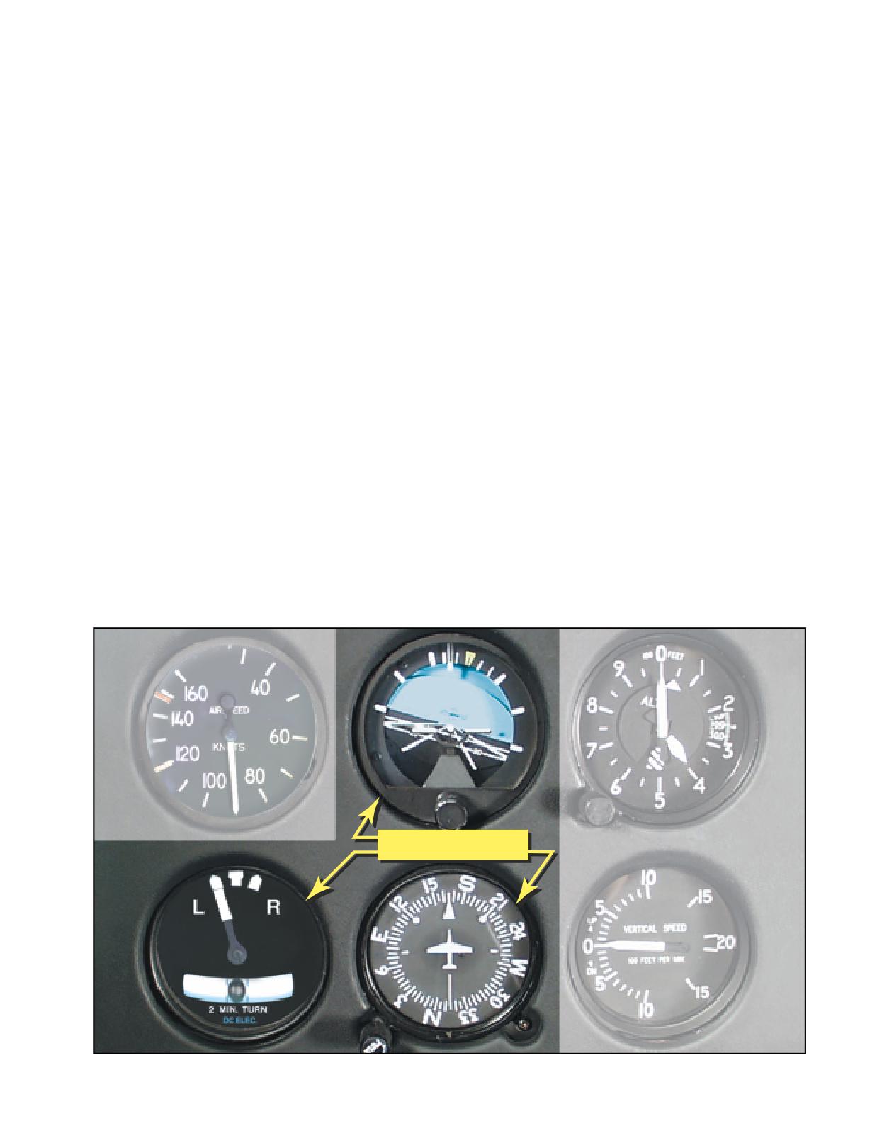
vertical speed indicator immediately, the results will
AIRSPEED INDICATOR
show on the altimeter as a gain or loss of altitude.
The airspeed indicator gives an indirect indication of
helicopter pitch attitude. With a given power setting
and pitch attitude, the airspeed remains constant. If the
The initial movement of the vertical speed needle is
airspeed increases, the nose is too low and should be
instantaneous and indicates the trend of the vertical
raised. If the airspeed decreases, the nose is too high
movement of the helicopter. It must be realized that
and should be lowered. A rapid change in airspeed indi-
a period of time is necessary for the vertical speed
cates a large change in pitch attitude, and a slow change
indicator to reach its maximum point of deflection
in airspeed indicates a small change in pitch attitude.
after a correction has been made. This time element
There is very little lag in the indications of the airspeed
is commonly referred to as “lag.” The lag is directly
indicator. If, while making attitude changes, you notice
proportional to the speed and magnitude of the pitch
some lag between control application and change of
change. If you employ smooth control techniques
airspeed, it is most likely due to cyclic control lag.
and make small adjustments in pitch attitude, lag is
Generally, a departure from the desired airspeed, due to
minimized, and the vertical speed indicator is easy
an inadvertent pitch attitude change, also results in a
to interpret. Overcontrolling can be minimized by
change in altitude. For example, an increase in airspeed
first neutralizing the controls and allowing the pitch
due to a low pitch attitude results in a decrease in alti-
attitude to stabilize; then readjusting the pitch atti-
tude. A correction in the pitch attitude regains both air-
tude by noting the indications of the other pitch
speed and altitude.
instruments.
BANK CONTROL
Occasionally, the vertical speed indicator may be
The bank attitude of a helicopter is the angular relation
slightly out of calibration. This could result in the
of its lateral axis and the natural horizon. To maintain a
instrument indicating a slight climb or descent even
straight course in visual flight, you must keep the
when the helicopter is in level flight. If it cannot be
lateral axis of the helicopter level with the natural hori-
readjusted properly, this error must be taken into con-
zon. Assuming the helicopter is in coordinated flight,
sideration when using the vertical speed indicator for
any deviation from a laterally level attitude produces a
pitch control. For example, if the vertical speed indica-
turn. [Figure 12-13]
tor showed a descent of 100 f.p.m. when the helicopter
was in level flight, you would have to use that indica-
ATTITUDE INDICATOR
tion as level flight. Any deviation from that reading
The attitude indicator gives a direct indication of the
would indicate a change in attitude.
bank attitude of the helicopter. For instrument flight,
BANK CONTROL
Figure 12-13. The flight instruments used for bank control are the attitude, heading, and turn indicators.
12-9
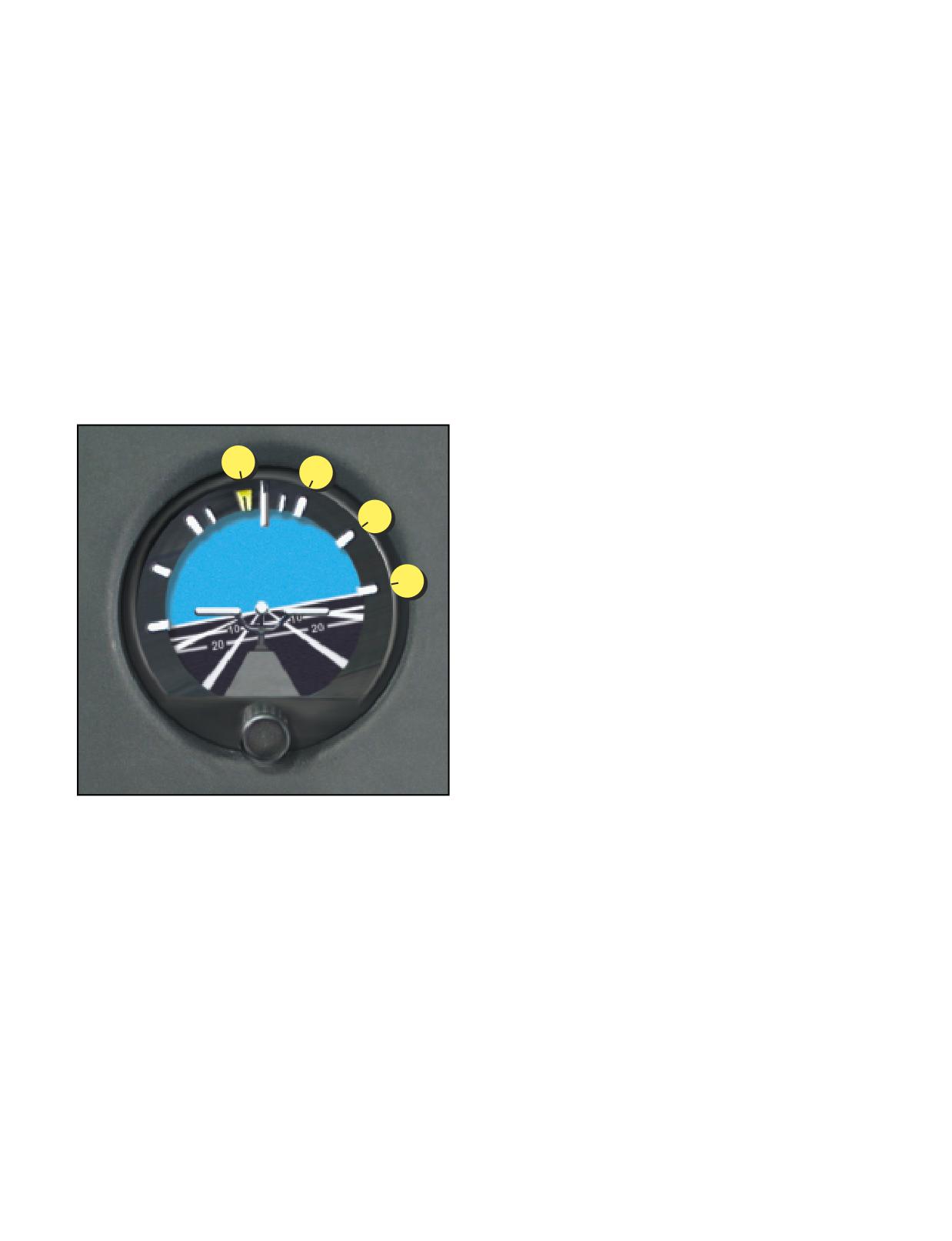
the miniature aircraft and the horizon bar of the attitude
the helicopter is still turning, make a small change of
indicator are substituted for the actual helicopter and
bank attitude to center the turn needle and stop the
the natural horizon. Any change in bank attitude of the
movement of the heading indicator.
helicopter is indicated instantly by the miniature air-
craft. For proper interpretations of this instrument, you
HEADING INDICATOR
should imagine being in the miniature aircraft. If the
In coordinated flight, the heading indicator gives an
helicopter is properly trimmed and the rotor tilts, a turn
indirect indication of the helicopter’s bank attitude.
begins. The turn can be stopped by leveling the miniature
When a helicopter is banked, it turns. When the lateral
aircraft with the horizon bar. The ball in the turn-and-slip
axis of the helicopter is level, it flies straight.
indicator should always be kept centered through proper
Therefore, in coordinated flight, when the heading indi-
pedal trim.
cator shows a constant heading, the helicopter is level
laterally. A deviation from the desired heading indi-
cates a bank in the direction the helicopter is turning.
The angle of bank is indicated by the pointer on the
A small angle of bank is indicated by a slow change of
banking scale at the top of the instrument. [Figure 12-
heading; a large angle of bank is indicated by a rapid
14] Small bank angles, which may not be seen by
change of heading. If a turn is noticed, apply opposite
observing the miniature aircraft, can easily be deter-
cyclic until the heading indicator indicates the desired
mined by referring to the banking scale pointer.
heading, simultaneously checking that the ball is cen-
tered. When making the correction to the desired head-
ing, you should not use a bank angle greater than that
required to achieve a standard rate turn. In addition, if
0°
30°
the number of degrees of change is small, limit the
bank angle to the number of degrees to be turned. Bank
angles greater than these require more skill and preci-
60°
sion in attaining the desired results. During straight-
and-level flight, the heading indicator is the primary
reference for bank control.
90°
TURN INDICATOR
During coordinated flight, the needle of the turn-and-
slip indicator gives an indirect indication of the bank
attitude of the helicopter. When the needle is dis-
placed from the vertical position, the helicopter is
turning in the direction of the displacement. Thus, if
the needle is displaced to the left, the helicopter is
turning left. Bringing the needle back to the vertical
position with the cyclic produces straight flight. A
close observation of the needle is necessary to accu-
rately interpret small deviations from the desired
position.
Figure 12-14. The banking scale at the top of the attitude indi-
cator indicates varying degrees of bank. In this example, the
helicopter is banked a little over 10° to the right.
Cross-check the ball of the turn-and-slip indicator to
determine that the helicopter is in coordinated flight. If
the rotor is laterally level and torque is properly com-
pensated for by pedal pressure, the ball remains in the
Pitch and bank attitudes can be determined simultane-
center. To center the ball, level the helicopter laterally
ously on the attitude indicator. Even though the miniature
by reference to the other bank instruments, then center
aircraft is not level with the horizon bar, pitch attitude can
the ball with pedal trim. Torque correction pressures
be established by observing the relative position of the
vary as you make power changes. Always check the
miniature aircraft and the horizon bar.
ball following such changes.
The attitude indicator may show small misrepresenta-
COMMON ERRORS DURING STRAIGHT-AND-
tions of bank attitude during maneuvers that involve
LEVEL FLIGHT
turns. This precession error can be immediately
1.
Failure to maintain altitude.
detected by closely cross-checking the other bank
2.
Failure to maintain heading.
instruments during these maneuvers. Precession nor-
3.
Overcontrolling pitch and bank during corrections.
mally is noticed when rolling out of a turn. If, on the
4.
Failure to maintain proper pedal trim.
completion of a turn, the miniature aircraft is level and
5.
Failure to cross-check all available instruments.
12-10
POWER CONTROL DURING STRAIGHT-AND-
speed is to be changed any appreciable amount, adjust
LEVEL FLIGHT
the torque so that it is approximately five percent over or
Establishing specific power settings is accomplished
under that setting necessary to maintain the new airspeed.
through collective pitch adjustments and throttle
As the power approaches the desired setting, include the
control, where necessary. For reciprocating powered
torque meter in the cross-check to determine when the
helicopters, power indications are observed on the
proper adjustment has been accomplished. As the air-
manifold pressure gauge. For turbine powered helicop-
speed is changing, adjust the pitch attitude to maintain a
ters, power is observed on the torque gauge. (Since most
constant altitude. A constant heading should be main-
IFR certified helicopters are turbine powered, this
tained throughout the change. As the desired airspeed is
discussion concentrates on this type of helicopter.)
approached, adjust power to the new cruising power set-
ting and further adjust pitch attitude to maintain altitude.
At any given airspeed, a specific power setting deter-
Overpowering and underpowering torque approximately
mines whether the helicopter is in level flight, in a
five percent results in a change of airspeed at a moderate
climb, or in a descent. For example, cruising airspeed
rate, which allows ample time to adjust pitch and bank
maintained with cruising power results in level flight.
smoothly. The instrument indications for straight-and-
If you increase the power setting and hold the airspeed
level flight at normal cruise, and during the transition
constant, the helicopter climbs. Conversely, if you
from normal cruise to slow cruise are illustrated in fig-
decrease power and hold the airspeed constant, the heli-
ures 12-15 and 12-16 on the next page. After the airspeed
copter descends. As a rule of thumb, in a turbine-engine
has stabilized at slow cruise, the attitude indicator shows
powered helicopter, a 10 to 15 percent change in the
an approximate level pitch attitude.
torque value required to maintain level flight results in a
climb or descent of approximately 500 f.p.m., if the air-
The altimeter is the primary pitch instrument during
speed remains the same.
level flight, whether flying at a constant airspeed, or
during a change in airspeed. Altitude should not change
If the altitude is held constant, power determines the
during airspeed transitions. The heading indicator
airspeed. For example, at a constant altitude, cruising
remains the primary bank instrument. Whenever the
power results in cruising airspeed. Any deviation from
airspeed is changed any appreciable amount, the torque
the cruising power setting results in a change of air-
meter is momentarily the primary instrument for power
speed. When power is added to increase airspeed, the
control. When the airspeed approaches that desired, the
nose of the helicopter pitches up and yaws to the right
airspeed indicator again becomes the primary instru-
in a helicopter with a counterclockwise main rotor
ment for power control.
blade rotation. When power is reduced to decrease air-
speed, the nose pitches down and yaws to the left. The
The cross-check of the pitch and bank instruments to
yawing effect is most pronounced in single-rotor helicop-
produce straight-and-level flight should be combined
ters, and is absent in helicopters with counter-rotating
with the power control instruments. With a constant
rotors. To counteract the yawing tendency of the helicop-
power setting, a normal cross-check should be
ter, apply pedal trim during power changes.
satisfactory. When changing power, the speed of the
cross-check must be increased to cover the pitch and
To maintain a constant altitude and airspeed in level
bank instruments adequately. This is necessary to
flight, coordinate pitch attitude and power control. The
counteract any deviations immediately.
relationship between altitude and airspeed determines
the need for a change in power and/or pitch attitude. If
COMMON ERRORS DURING AIRSPEED CHANGES
the altitude is constant and the airspeed is high or low,
1.
Improper use of power.
change the power to obtain the desired airspeed.
2.
Overcontrolling pitch attitude.
During the change in power, make an accurate inter-
3.
Failure to maintain heading.
pretation of the altimeter; then counteract any devia-
4.
Failure to maintain altitude.
tion from the desired altitude by an appropriate change
5.
Improper pedal trim.
of pitch attitude. If the altitude is low and the airspeed
is high, or vice versa, a change in pitch attitude alone
STRAIGHT CLIMBS (CONSTANT AIRSPEED
may return the helicopter to the proper altitude and air-
AND CONSTANT RATE)
speed. If both airspeed and altitude are low, or if both
For any power setting and load condition, there is only
are high, a change in both power and pitch attitude is
one airspeed that will give the most efficient rate of
necessary.
climb. To determine this, you should consult the climb
data for the type of helicopter being flown. The tech-
To make power control easy when changing airspeed, it
nique varies according to the airspeed on entry and
is necessary to know the approximate power settings for
whether you want to make a constant airspeed or con-
the various airspeeds that will be flown. When the air-
stant rate climb.
12-11
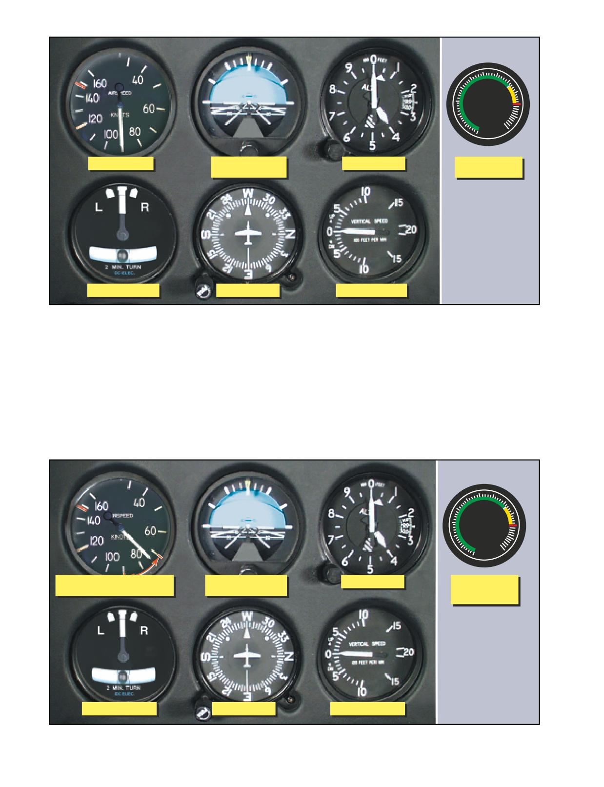
60 70
50
80
40
TORQUE
90
30
100
20
PERCENT
110
10
120
0
Primary Power
Supporting Pitch
Primary Pitch
Supporting
and Bank
Power
Supporting Bank
Primary Bank
Supporting Pitch
Figure 12-15. Flight instrument indications in straight-and-level flight at normal cruise speed.
ENTRY
accomplish the pitch change. If the transition from
To enter a constant airspeed climb from cruise airspeed,
level flight to a climb is smooth, the vertical speed indi-
when the climb speed is lower than cruise speed, simul-
cator shows an immediate upward trend and then stops
taneously increase power to the climb power setting
at a rate appropriate to the stabilized airspeed and atti-
and adjust pitch attitude to the approximate climb atti-
tude. Primary and supporting instruments for climb
tude. The increase in power causes the helicopter to
entry are illustrated in figure 12-17.
start climbing and only very slight back cyclic pressure
is needed to complete the change from level to climb
When the helicopter stabilizes on a constant airspeed
attitude. The attitude indicator should be used to
and attitude, the airspeed indicator becomes primary
60 70
50
80
40
TORQUE
90
30
100
20
PERCENT110
10
120
0
Primary Power as Airspeed
Supporting Pitch
Primary Pitch
Primary
Approaches Desired Value
and Bank
Power
Initially
Supporting Bank
Primary Bank
Supporting Pitch
Figure 12-16. Flight instrument indications in straight-and-level flight with airspeed decreasing.
12-12
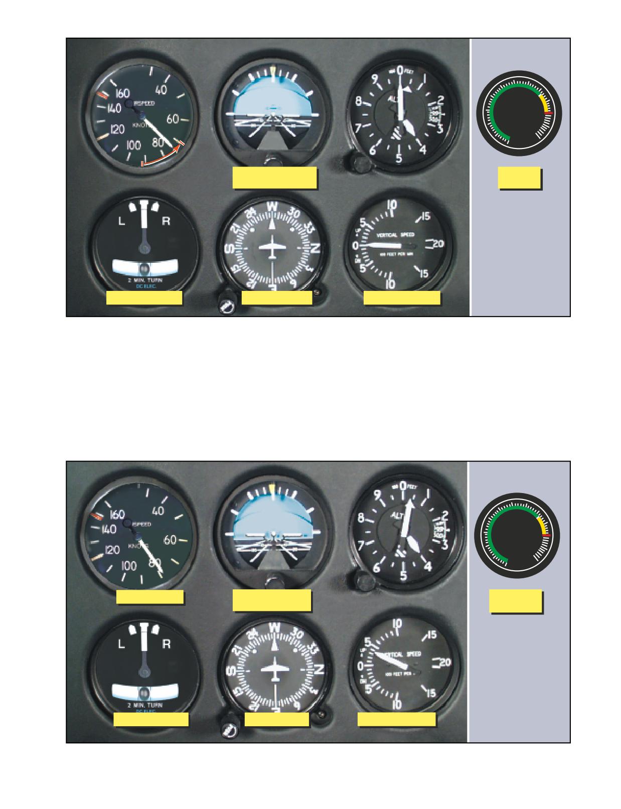
60 70
50
80
40
TORQUE
90
30
100
20
PERCENT110
10
120
0
Primary Pitch
Primary
Supporting Bank
Power
Supporting Bank
Primary Bank
Supporting Pitch
Figure 12-17. Flight instrument indications during climb entry for a constant airspeed climb.
for pitch. The torque meter continues to be primary for
The technique and procedures for entering a constant
power and should be monitored closely to determine if
rate climb are very similar to those previously
the proper climb power setting is being maintained.
described for a constant airspeed climb. For training
Primary and supporting instruments for a stabilized
purposes, a constant rate climb is entered from climb
constant airspeed climb are shown in figure 12-18.
airspeed. The rate used is the one that is appropriate for
60 70
50
80
40
TORQUE
90
30
100
20
PERCENT110
10
120
0
Primary Pitch
Supporting Pitch
Primary
and Bank
Power
Supporting Bank
Primary Bank
Supporting Pitch
Figure 12-18. Flight instrument indications in a stabilized, constant airspeed climb.
12-13
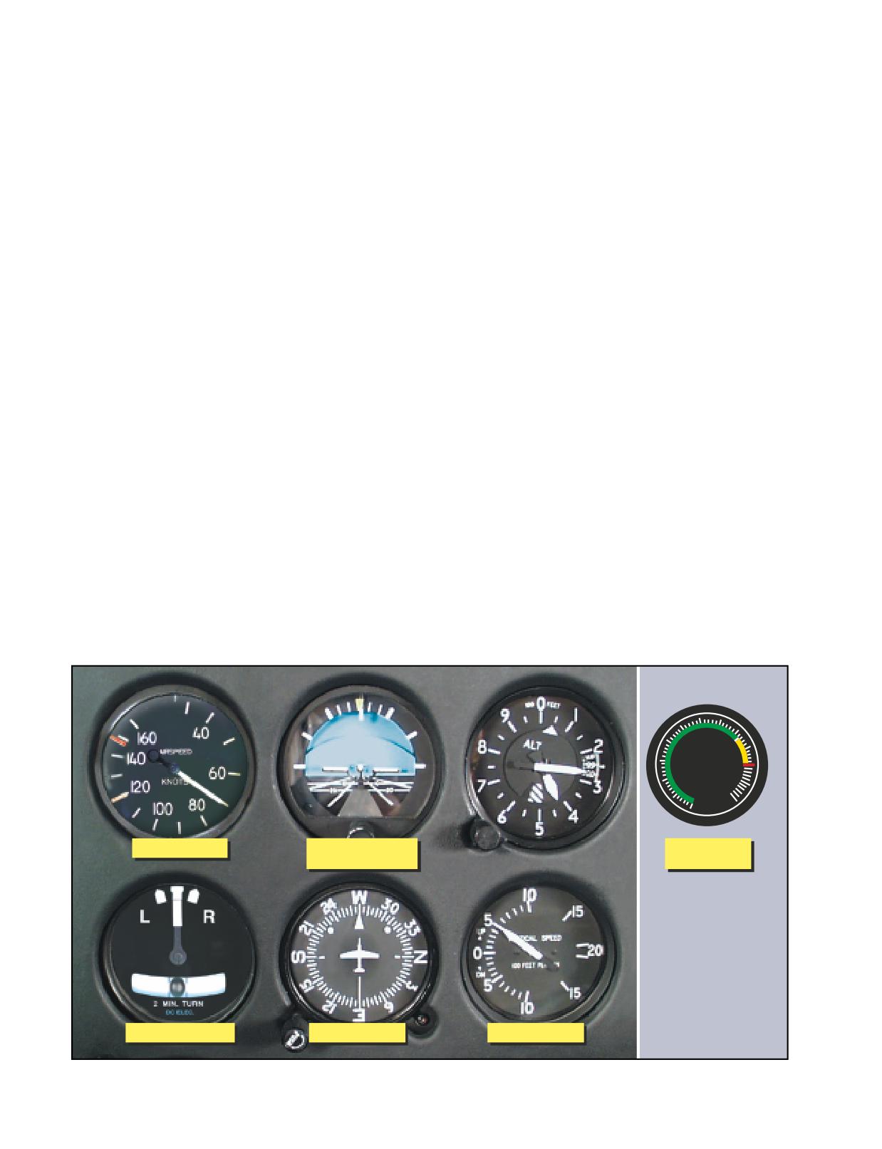
the particular helicopter being flown. Normally, in heli-
rate of climb is 500 f.p.m., initiate the leveloff approxi-
copters with low climb rates, 500 f.p.m. is appropriate,
mately 50 feet before the desired altitude. When the
in helicopters capable of high climb rates, use a rate of
proper lead altitude is reached, the altimeter becomes
1,000 f.p.m.
primary for pitch. Adjust the pitch attitude to the level
flight attitude for that airspeed. Cross-check the altime-
To enter a constant rate climb, increase power to the
ter and VSI to determine when level flight has been
approximate setting for the desired rate. As power is
attained at the desired altitude. To level off at cruise air-
applied, the airspeed indicator is primary for pitch until
speed, if this speed is higher than climb airspeed, leave
the vertical speed approaches the desired rate. At this
the power at the climb power setting until the airspeed
time, the vertical speed indicator becomes primary for
approaches cruise airspeed, then reduce it to the cruise
pitch. Change pitch attitude by reference to the attitude
power setting.
indicator to maintain the desired vertical speed. When
The leveloff from a constant rate climb is accomplished
the VSI becomes primary for pitch, the airspeed indica-
in the same manner as the leveloff from a constant air-
tor becomes primary for power. Primary and supporting
speed climb.
instruments for a stabilized constant rate climb are illus-
trated in figure 12-19. Adjust power to maintain desired
STRAIGHT DESCENTS (CONSTANT
airspeed. Pitch attitude and power corrections should be
AIRSPEED AND CONSTANT RATE)
closely coordinated. To illustrate this, if the vertical
A descent may be performed at any normal airspeed the
speed is correct but the airspeed is low, add power. As
helicopter is capable of, but the airspeed must be deter-
power is increased, it may be necessary to lower the
mined prior to entry. The technique is determined by
pitch attitude slightly to avoid increasing the vertical
whether you want to perform a constant airspeed or a
rate. Adjust the pitch attitude smoothly to avoid over-
constant rate descent.
controlling. Small power corrections usually will be
sufficient to bring the airspeed back to the desired indi-
ENTRY
cation.
If your airspeed is higher than descending airspeed, and
you wish to make a constant airspeed descent at the
LEVELOFF
descending airspeed, reduce power to the descending
The leveloff from a constant airspeed climb must be
power setting and maintain a constant altitude using
started before reaching the desired altitude. Although the
cyclic pitch control. When you approach the descend-
amount of lead varies with the helicopter being flown
ing airspeed, the airspeed indicator becomes primary
and your piloting technique, the most important factor is
for pitch, and the torque meter is primary for power. As
vertical speed. As a rule of thumb, use 10 percent of the
you hold the airspeed constant, the helicopter begins to
vertical velocity as your lead point. For example, if the
descend. For a constant rate descent, reduce the power
60 70
50
80
40
TORQUE
90
30
100
20
PERCENT110
10
120
0
Primary Power
Supporting Pitch
Supporting
and Bank
Power
Supporting Bank
Primary Bank
Primary Pitch
Figure 12-19. Flight instrument indications in a stabilized constant rate climb.
12-14
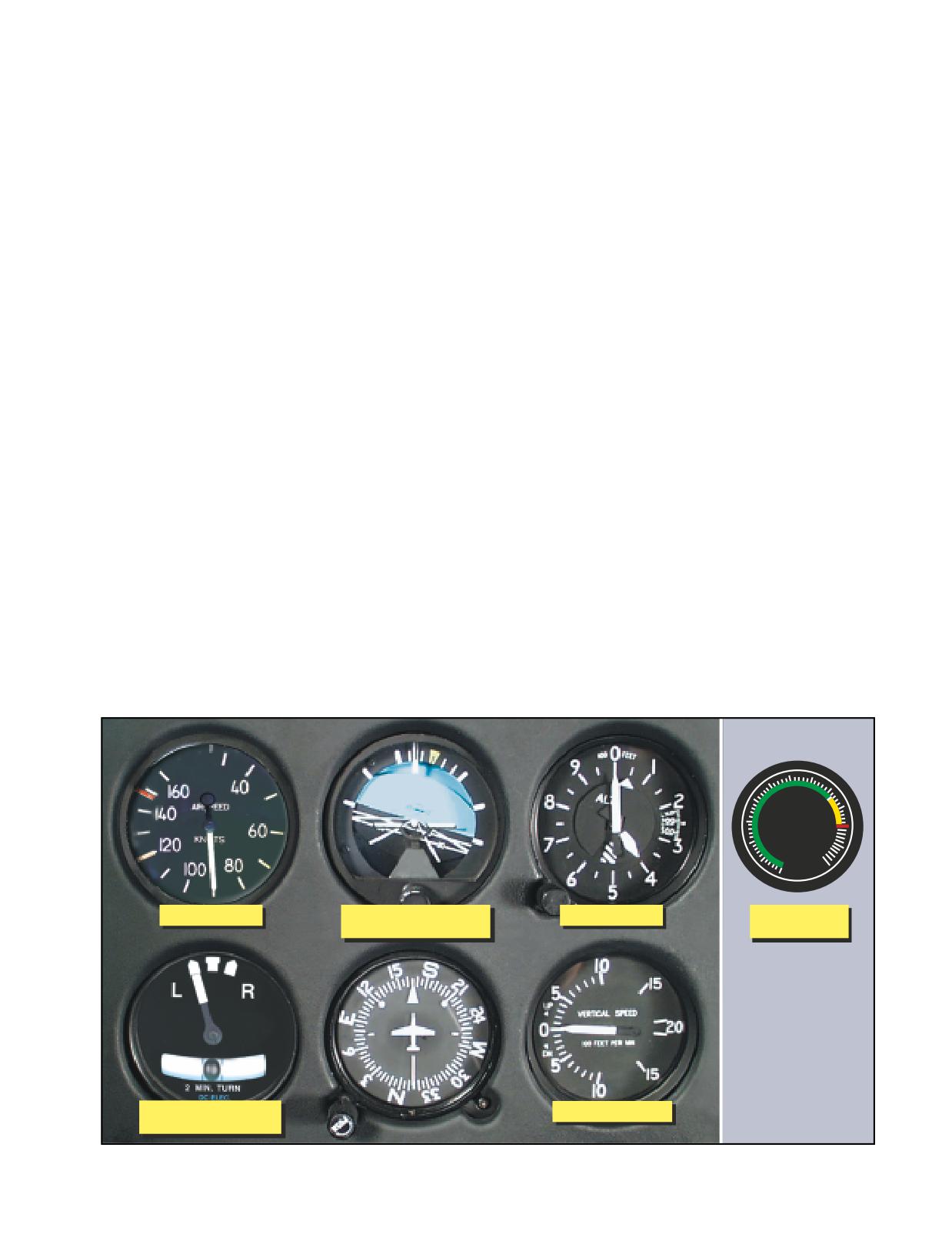
to the approximate setting for the desired rate. If the
COMMON ERRORS DURING STRAIGHT CLIMBS
descent is started at the descending airspeed, the air-
AND DESCENTS
speed indicator is primary for pitch until the VSI
1.
Failure to maintain heading.
approaches the desired rate. At this time, the vertical
2.
Improper use of power.
speed indicator becomes primary for pitch, and the
3.
Poor control of pitch attitude.
airspeed indicator becomes primary for power.
4.
Failure to maintain proper pedal trim.
Coordinate power and pitch attitude control as was
5.
Failure to level off on desired altitude.
described earlier for constant rate climbs.
TURNS
LEVELOFF
When making turns by reference to the flight instru-
The leveloff from a constant airspeed descent may be
ments, they should be made at a definite rate. Turns
made at descending airspeed or at cruise airspeed, if
described in this chapter are those that do not exceed a
this is higher than descending airspeed. As in a climb
standard rate of 3° per second as indicated on the turn-
leveloff, the amount of lead depends on the rate of
and-slip indicator. True airspeed determines the angle
descent and control technique. For a leveloff at
of bank necessary to maintain a standard rate turn. A
descending airspeed, the lead should be approximately
rule of thumb to determine the approximate angle of
10 percent of the vertical speed. At the lead altitude,
bank required for a standard rate turn is to divide your
simultaneously increase power to the setting necessary
airspeed by 10 and add one-half the result. For exam-
to maintain descending airspeed in level flight. At this
ple, at 60 knots, approximately 9° of bank is required
point, the altimeter becomes primary for pitch, and the
(60 ÷ 10 = 6 + 3 = 9); at 80 knots, approximately 12° of
airspeed indicator becomes primary for power.
bank is needed for a standard rate turn.
To level off at a higher airspeed than descending air-
speed, increase the power approximately 100 to 150 feet
To enter a turn, apply lateral cyclic in the direction of the
prior to reaching the desired altitude. The power setting
desired turn. The entry should be accomplished
should be that which is necessary to maintain the
smoothly, using the attitude indicator to establish the
desired airspeed in level flight. Hold the vertical speed
approximate bank angle. When the turn indicator indi-
constant until approximately 50 feet above the desired
cates a standard rate turn, it becomes primary for bank.
altitude. At this point, the altimeter becomes primary
The attitude indicator now becomes a supporting instru-
for pitch, and the airspeed indicator becomes primary
ment. During level turns, the altimeter is primary for
for power. The leveloff from a constant rate descent
pitch, and the airspeed indicator is primary for power.
should be accomplished in the same manner as the lev-
Primary and supporting instruments for a stabilized stan-
eloff from a constant airspeed descent.
dard rate turn are illustrated in figure 12-20. If an
60 70
50
80
40
TORQUE
90
30
100
20
PERCENT110
10
120
0
Primary Power
Primary Bank Initially
Primary Pitch
Supporting
Supporting Pitch
Power
Primary Bank as
Supporting Pitch
Turn is Established
Figure 12-20. Flight instrument indications for a standard rate turn to the left.
12-15
increase in power is required to maintain airspeed, slight
You use the same cross-check and control technique in
forward cyclic pressure may be required since the heli-
making timed turns that you use to make turns to a pre-
copter tends to pitch up as collective pitch angle is
determined heading, except that you substitute the
increased. Apply pedal trim, as required, to keep the ball
clock for the heading indicator. The needle of the turn-
centered.
and-slip indicator is primary for bank control, the
altimeter is primary for pitch control, and the airspeed
To recover to straight-and-level flight, apply cyclic in
indicator is primary for power control. Begin the roll-in
the direction opposite the turn. The rate of roll-out
when the clock’s second hand passes a cardinal point,
should be the same as the rate used when rolling into
hold the turn at the calibrated standard-rate indication,
the turn. As you initiate the turn recover, the attitude
or half-standard-rate for small changes in heading, and
indicator becomes primary for bank. When the helicop-
begin the roll-out when the computed number of sec-
ter is approximately level, the heading indicator
onds has elapsed. If the roll-in and roll-out rates are the
becomes primary for bank as in straight-and-level
same, the time taken during entry and recovery need
flight. Cross-check the airspeed indicator and ball
not be considered in the time computation.
closely to maintain the desired airspeed and pedal trim.
If you practice timed turns with a full instrument panel,
TURNS TO A PREDETERMINED HEADING
check the heading indicator for the accuracy of your
A helicopter turns as long as its lateral axis is tilted; there-
turns. If you execute the turns without the heading indi-
fore, the recovery must start before the desired heading is
cator, use the magnetic compass at the completion of
reached. The amount of lead varies with the rate of turn
the turn to check turn accuracy, taking compass devia-
and your piloting technique.
tion errors into consideration.
As a guide, when making a 3° per second rate of turn,
CHANGE OF AIRSPEED IN TURNS
use a lead of one-half the bank angle. For example, if
Changing airspeed in turns is an effective maneuver for
you are using a 12° bank angle, use half of that, or 6°,
increasing your proficiency in all three basic instru-
as the lead point prior to your desired heading. Use this
ment skills. Since the maneuver involves simultaneous
lead until you are able to determine the exact amount
changes in all components of control, proper execution
required by your particular technique. The bank angle
requires a rapid cross-check and interpretation, as well
should never exceed the number of degrees to be
as smooth control. Proficiency in the maneuver also
turned. As in any standard rate turn, the rate of recov-
contributes to your confidence in the instruments dur-
ery should be the same as the rate for entry. During
ing attitude and power changes involved in more com-
turns to predetermined headings, cross-check the pri-
plex maneuvers.
mary and supporting pitch, bank, and power instru-
ments closely.
Pitch and power control techniques are the same as
those used during airspeed changes in straight-and-
TIMED TURNS
level flight. As discussed previously, the angle of bank
A timed turn is a turn in which the clock and turn-and-
necessary for a given rate of turn is proportional to the
slip indicator are used to change heading a definite
true airspeed. Since the turns are executed at standard
number of degrees in a given time. For example, using
rate, the angle of bank must be varied in direct pro-
a standard rate turn, a helicopter turns 45° in 15 sec-
portion to the airspeed change in order to maintain a
onds. Using a half-standard rate turn, the helicopter
constant rate of turn. During a reduction of airspeed,
turns 45° in 30 seconds. Timed turns can be used if
you must decrease the angle of bank and increase the
your heading indicator becomes inoperative.
pitch attitude to maintain altitude and a standard rate
turn.
Prior to performing timed turns, the turn coordinator
should be calibrated to determine the accuracy of its
The altimeter and the needle on the turn indicator
indications. To do this, establish a standard rate turn by
should remain constant throughout the turn. The
referring to the turn-and-slip indicator. Then as the
altimeter is primary for pitch control, and the turn nee-
sweep second hand of the clock passes a cardinal point
dle is primary for bank control. The torque meter is
(12, 3, 6, or 9), check the heading on the heading indi-
primary for power control while the airspeed is chang-
cator. While holding the indicated rate of turn constant,
ing. As the airspeed approaches the new indication, the
note the heading changes at 10-second intervals. If the
airspeed indicator becomes primary for power control.
helicopter turns more or less than 30° in that interval, a
smaller or larger deflection of the needle is necessary
Two methods of changing airspeed in turns may be
to produce a standard rate turn. When you have cali-
used. In the first method, airspeed is changed after the
brated the turn-and-slip indicator during turns in each
turn is established. In the second method, the airspeed
direction, note the corrected deflections, if any, and
change is initiated simultaneously with the turn entry.
apply them during all timed turns.
The first method is easier, but regardless of the method
12-16
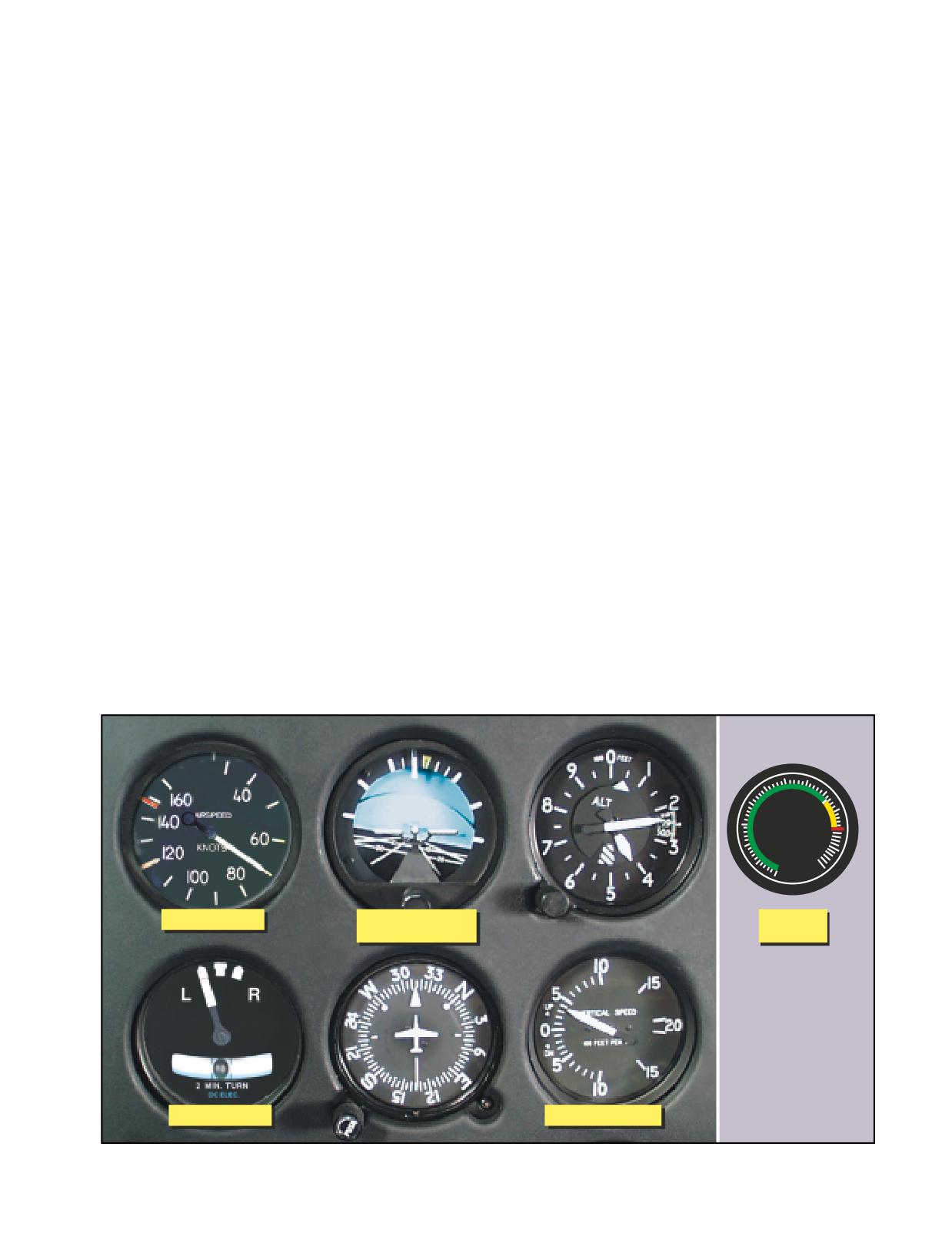
used, the rate of cross-check must be increased as you
indicator, and make the necessary adjustments. After
reduce power. As the helicopter decelerates, check the
you have made this change, again check the altimeter
altimeter and VSI for needed pitch changes, and the
and vertical speed indicator to determine whether or
bank instruments for needed bank changes. If the needle
not the correction was adequate.
of the turn-and-slip indicator shows a deviation from
the desired deflection, change the bank. Adjust pitch
CLIMBING AND DESCENDING TURNS
attitude to maintain altitude. When the airspeed
For climbing and descending turns, the techniques
approaches that desired, the airspeed indicator becomes
described earlier for straight climbs and descents and
primary for power control. Adjust the torque meter to
those for standard rate turns are combined. For practice,
maintain the desired airspeed. Use pedal trim to ensure
start the climb or descent and turn simultaneously. The
the maneuver is coordinated.
primary and supporting instruments for a stabilized con-
stant airspeed left climbing turn are illustrated in figure
Until your control technique is very smooth, frequently
12-21. The leveloff from a climbing or descending turn
cross-check the attitude indicator to keep from over-
is the same as the leveloff from a straight climb or
controlling and to provide approximate bank angles
descent. To recover to straight-and-level flight, you may
appropriate for the changing airspeeds.
stop the turn and then level off, level off and then stop
the turn, or simultaneously level off and stop the turn.
30° BANK TURN
During climbing and descending turns, keep the ball of
A turn using 30° of bank is seldom necessary, or advis-
the turn indicator centered with pedal trim.
able, in IMC, but it is an excellent maneuver to increase
your ability to react quickly and smoothly to rapid
COMPASS TURNS
changes of attitude. Even though the entry and recov-
The use of gyroscopic heading indicators make head-
ery technique are the same as for any other turn, you
ing control very easy. However, if the heading indica-
will probably find it more difficult to control pitch
tor fails or your helicopter does not have one installed,
because of the decrease in vertical lift as the bank
you must use the magnetic compass for heading refer-
increases. Also, because of the decrease in vertical lift,
ence. When making compass-only turns, you need to
there is a tendency to lose altitude and/or airspeed.
adjust for the lead or lag created by acceleration and
Therefore, to maintain a constant altitude and airspeed,
deceleration errors so that you roll out on the desired
additional power is required. You should not initiate a
heading. When turning to a heading of north, the lead
correction, however, until the instruments indicate the
for the roll-out must include the number of degrees of
need for a correction. During the maneuver, note the
your latitude plus the lead you normally use in recov-
need for a correction on the altimeter and vertical speed
ery from turns. During a turn to a south heading, main-
indicator, then check the indications on the attitude
tain the turn until the compass passes south the number
60 70
50
80
40
TORQUE
90
30
100
20
PERCENT110
10
120
0
Primary Pitch
Supporting Pitch
Primary
and Bank
Power
Primary Bank
Supporting Pitch
Figure 12-21. Flight instrument indications for a stabilized left climbing turn at a constant airspeed.
12-17
of degrees of your latitude, minus your normal roll-out
COMMON ERRORS DURING
lead. For example, when turning from an easterly
UNUSUAL ATTITUDE RECOVERIES
direction to north, where the latitude is 30°, start the
1.
Failure to make proper pitch correction.
roll-out when the compass reads 037° (30° plus one-
2.
Failure to make proper bank correction.
half the 15° angle of bank, or whatever amount is
3.
Failure to make proper power correction.
appropriate for your rate of roll-out). When turning
4.
Overcontrol of pitch and/or bank attitude.
from an easterly direction to south, start the roll-out
5.
Overcontrol of power.
when the magnetic compass reads 203° (180° plus 30°
6.
Excessive loss of altitude.
minus one-half the angle of bank). When making sim-
ilar turns from a westerly direction, the appropriate
EMERGENCIES
points at which to begin your roll-out would be 323°
Emergencies under instrument flight are handled simi-
for a turn to north, and 157° for a turn to south.
larly to those occurring during VFR flight. A thorough
knowledge of the helicopter and its systems, as well as
COMMON ERRORS DURING TURNS
good aeronautical knowledge and judgment, prepares
1.
Failure to maintain desired turn rate.
you to better handle emergency situations. Safe opera-
2.
Failure to maintain altitude in level turns.
tions begin with preflight planning and a thorough pre-
3.
Failure to maintain desired airspeed.
flight. Plan your route of flight so that there are adequate
4.
Variation in the rate of entry and recovery.
landing sites in the event you have to make an emer-
5.
Failure to use proper lead in turns to a heading.
gency landing. Make sure you have all your resources,
6.
Failure to properly compute time during timed turns.
such as maps, publications, flashlights, and fire extin-
7.
Failure to use proper leads and lags during the
guishers readily available for use in an emergency.
compass turns.
8.
Improper use of power.
During any emergency, you should first fly the aircraft.
9.
Failure to use proper pedal trim.
This means that you should make sure the helicopter is
under control, including the determination of emergency
UNUSUAL ATTITUDES
landing sites. Then perform the emergency checklist
Any maneuver not required for normal helicopter instru-
memory items, followed by written items in the RFM.
ment flight is an unusual attitude and may be caused by
Once all these items are under control, you should notify
any one or a combination of factors, such as turbulence,
ATC. Declare any emergency on the last assigned ATC
disorientation, instrument failure, confusion, preoccupa-
frequency, or if one was not issued, transmit on the emer-
tion with cockpit duties, carelessness in cross-checking,
gency frequency 121.5. Set the transponder to the emer-
errors in instrument interpretation, or lack of proficiency
gency squawk code 7700. This code triggers an alarm or
in aircraft control. Due to the instability characteristics
a special indicator in radar facilities.
of the helicopter, unusual attitudes can be extremely crit-
ical. As soon as you detect an unusual attitude, make a
Most in-flight emergencies, including low fuel and a
recovery to straight-and-level flight as soon as possible
complete electrical failure, require you to land as soon
with a minimum loss of altitude.
as possible. In the event of an electrical fire, turn all non-
essential equipment off and land immediately. Some
To recover from an unusual attitude, correct bank and
essential electrical instruments, such as the attitude indi-
pitch attitude, and adjust power as necessary. All com-
cator, may be required for a safe landing. A navigation
ponents are changed almost simultaneously, with little
radio failure may not require an immediate landing as
lead of one over the other. You must be able to perform
long as the flight can continue safely. In this case, you
this task with and without the attitude indicator. If the
should land as soon as practical. ATC may be able to
helicopter is in a climbing or descending turn, correct
provide vectors to a safe landing area. For the specific
bank, pitch, and power. The bank attitude should be
details on what to do during an emergency, you should
corrected by referring to the turn-and-slip indicator and
refer to the RFM for the helicopter you are flying.
attitude indicator. Pitch attitude should be corrected by
reference to the altimeter, airspeed indicator, VSI, and
attitude indicator. Adjust power by referring to the air-
speed indicator and torque meter.
Land as soon as possible-Land without delay at the nearest suitable
area, such as an open field, at which a safe approach and landing is
Since the displacement of the controls used in recover-
assured.
ies from unusual attitudes may be greater than those for
normal flight, take care in making adjustments as
Land immediately-The urgency of the landing is paramount. The pri-
mary consideration is to assure the survival of the occupants. Landing in
straight-and-level flight is approached. Cross-check the
trees, water, or other unsafe areas should be considered only as a last
other instruments closely to avoid overcontrolling.
resort.
Land as soon as practical-The landing site and duration of flight are
at the discretion of the pilot. Extended flight beyond the nearest
approved landing area is not recommended.
12-18
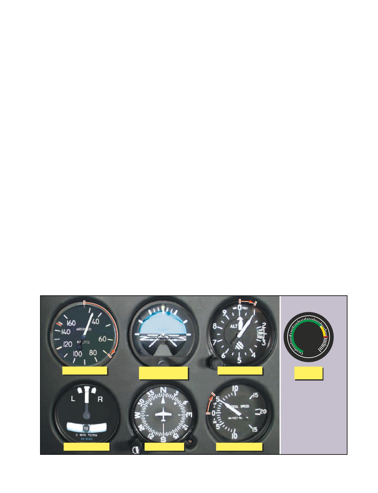
AUTOROTATIONS
If an antitorque or collective servo fails, you might be
Both straight-ahead and turning autorotations should
able to continue to the next suitable landing site.
be practiced by reference to instruments. This training
will ensure that you can take prompt corrective action
INSTRUMENT TAKEOFF
to maintain positive aircraft control in the event of an
This maneuver should only be performed as part of
engine failure.
your training for an instrument rating. The procedures
and techniques described here should be modified, as
To enter autorotation, reduce collective pitch smoothly
necessary, to conform with those set forth in the operat-
to maintain a safe rotor r.p.m. and apply pedal trim to
ing instructions for the particular helicopter being
keep the ball of the turn-and-slip indicator centered.
flown.
The pitch attitude of the helicopter should be approxi-
Adjust the miniature aircraft in the attitude indicator,
mately level as shown by the attitude indicator. The
as appropriate, for the aircraft being flown. After the
airspeed indicator is the primary pitch instrument and
helicopter is aligned with the runway or takeoff pad, to
should be adjusted to the recommended autorotation
prevent forward movement of a helicopter equipped
speed. The heading indicator is primary for bank in a
with a wheel-type landing gear, set the parking brake
straight-ahead autorotation. In a turning autorotation, a
or apply the toe brakes. If the parking brake is used, it
standard rate turn should be maintained by reference to
must be unlocked after the takeoff has been completed.
the needle of the turn-and-slip indicator.
Apply sufficient friction to the collective pitch control to
minimize overcontrolling and to prevent creeping.
COMMON ERRORS DURING AUTOROTATIONS
Excessive friction should be avoided since this limits
1. Uncoordinated entry due to improper pedal trim.
collective pitch movement.
2. Poor airspeed control due to improper pitch attitude.
3. Poor heading control in straight-ahead autorotations.
After checking all instruments for proper indications,
4. Failure to maintain proper rotor r.p.m.
start the takeoff by applying collective pitch and a prede-
5. Failure to maintain a standard rate turn during turn-
termined power setting. Add power smoothly and
ing autorotations.
steadily to gain airspeed and altitude simultaneously and
to prevent settling to the ground. As power is applied and
SERVO FAILURE
the helicopter becomes airborne, use the antitorque ped-
Most helicopters certified for single-pilot IFR flight are
als initially to maintain the desired heading. At the same
required to have autopilots, which greatly reduces pilot
time, apply forward cyclic to begin accelerating to
workload. If an autopilot servo fails, however, you
climbing airspeed. During the initial acceleration, the
have to resume manual control of the helicopter. How
pitch attitude of the helicopter, as read on the attitude
much your workload increases, depends on which
indicator, should be one to two bar widths low. The pri-
servo fails. If a cyclic servo fails, you may want to land
mary and supporting instruments after becoming airborne
immediately as the workload increases tremendously.
are illustrated in figure 12-22. As the airspeed increases
60 70
50
80
40
TORQUE
90
30
100
20
PERCENT 110
10
120
0
Supporting Pitch
Primary Pitch
Supporting Pitch
Primary
Supporting Bank
Power
Supporting Bank
Primary Bank
Supporting Pitch
Figure 12-22. Flight instrument indications during an instrument takeoff.
12-19
to the appropriate climb airspeed, adjust pitch gradually
be rapid and accurate, and aircraft control positive
to climb attitude. As climb airspeed is reached, reduce
and smooth.
power to the climb power setting and transition to a fully
coordinated straight climb.
COMMON ERRORS DURING INSTRUMENT
TAKEOFFS
During the initial climbout, minor heading correc-
1.
Failure to maintain heading.
tions should be made with pedals only until suffi-
2.
Overcontrolling pedals.
cient airspeed is attained to transition to fully
3.
Failure to use required power.
coordinated flight. Throughout the instrument take-
4.
Failure to adjust pitch attitude as climbing air-
off, instrument cross-check and interpretations must
speed is reached.
12-20
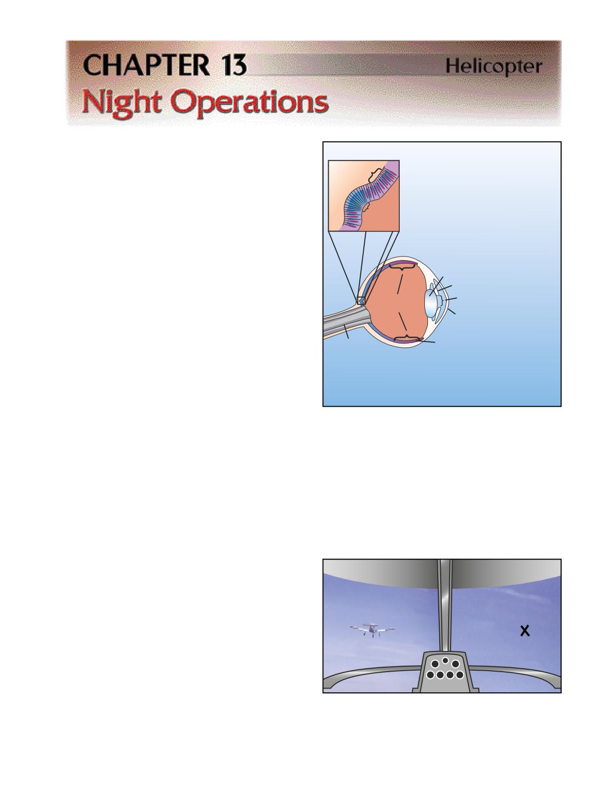
Flying at night can be a very pleasant experience. The
air is generally cooler and smoother, resulting in better
Rods and
The rods and cones (film) of the retina
helicopter performance and a more comfortable flight.
Cones
are the receptors, which record the
You generally also experience less traffic and less radio
image and transmit it through the optic
congestion.
nerve to the brain for interpretation.
Fovea
NIGHT FLIGHT PHYSIOLOGY
(All Cones)
Before discussing night operations, it is important you
understand how your vision is affected at night and
The pupil (aperture) is the
how to counteract the visual illusions, which you might
opening at the center of
encounter.
Lens
the iris. The size of the
pupil is adjusted to
Iris
control the amount
VISION IN FLIGHT
Rod
Pupil
of light entering
Concentration
the eye.
Vision is by far the most important sense that you
Cornea
have, and flying is obviously impossible without it.
Most of the things you perceive while flying are
Retina
Light passes
visual or heavily supplemented by vision. The visual
Optic Nerve
through the cornea
sense is especially important in collision avoidance
(the transparent window on
and depth perception. Your vision sensors are your
the front of the eye) and then through
the lens to focus on the retina.
eyes, even though they are not perfect in the way they
function or see objects. Since your eyes are not
always able to see all things at all times, illusions and
Figure 13-1. A camera is able to focus on near and far objects
blindspots occur. The more you understand the eye
by changing the distance between the lens and the film. You
and how it functions, the easier it is to compensate for
can see objects clearly at various distances because the
these illusions and blindspots.
shape of your eye’s lens is changed automatically by small
muscles.
THE EYE
The eye works in much the same way as a camera. Both
Directly behind the lens, on the retina, is a small,
have an aperture, lens, method of focusing, and a sur-
notched area called the fovea. This area contains only
face for registering images. [Figure 13-1].
a high concentration of cone receptors. When you
look directly at an object, the image is focused
Vision is primarily the result of light striking a photo-
mainly on the fovea. The cones, however, do not
sensitive layer, called the retina, at the back of the eye.
The retina is composed of light-sensitive cones and
rods. The cones in your eye perceive an image best
when the light is bright, while the rods work best in low
light. The pattern of light that strikes the cones and rods
is transmitted as electrical impulses by the optic nerve
to the brain where these signals are interpreted as an
image. The area where the optic nerve meets the retina
contains no cones or rods, creating a blind spot in
vision. Normally, each eye compensates for the other’s
blind spot. [Figure 13-2]
CONES
Figure 13-2. This illustration provides a dramatic example of
Cones are concentrated around the center of the
the eye’s blind spot. Cover your right eye and hold this page
retina. They gradually diminish in number as the dis-
at arm’s length. Focus your left eye on the X in the right side
tance from the center increases. Cones allow you to
of the visual, and notice what happens to the aircraft as you
perceive color by sensing red, blue, and green light.
slowly bring the page closer to your eye.
13-1
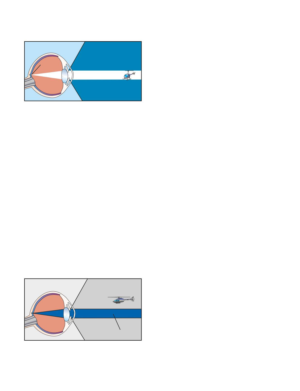
function well in darkness, which explains why you
How well you see at night is determined by the rods in
cannot see color as vividly at night as you can during
your eyes, as well as the amount of light allowed into
the day. [Figure 13-3]
your eyes. The wider the pupil is open at night, the bet-
ter your night vision becomes.
Cones Active
NIGHT VISION
The cones in your eyes adapt quite rapidly to changes in
Focus on
light intensities, but the rods do not. If you have ever
Fovea
walked from bright sunlight into a dark movie theater, you
have experienced this dark adaptation period. The rods
can take approximately 30 minutes to fully adapt to the
dark. A bright light, however, can completely destroy your
night adaptation and severely restrict your visual acuity.
There are several things you can do to keep your eyes
Figure 13-3. The best vision in daylight is obtained by look-
ing directly at the object. This focuses the image on the
adapted to the dark. The first is obvious; avoid bright
fovea, where detail is best seen.
lights before and during the flight. For 30 minutes
before a night flight, avoid any bright light sources,
such as headlights, landing lights, strobe lights, or
RODS
flashlights. If you encounter a bright light, close one
The rods are our dim light and night receptors and are
eye to keep it light sensitive. This allows you to see
concentrated outside the fovea area. The number of
again once the light is gone. Light sensitivity also can
rods increases as the distance from the fovea increases.
be gained by using sunglasses if you will be flying from
Rods sense images only in black and white. Because
daylight into an area of increasing darkness.
the rods are not located directly behind the pupil, they
are responsible for much of our peripheral vision.
Red cockpit lighting also helps preserve your night
Images that move are perceived more easily by the rod
vision, but red light severely distorts some colors, and
areas than by the cones in the fovea. If you have ever
completely washes out the color red. This makes read-
seen something move out of the corner of your eye, it
ing an aeronautical chart difficult. A dim white light or
was most likely detected by your rod receptors.
carefully directed flashlight can enhance your night
reading ability. While flying at night, keep the instru-
Since the cones do not function well in the dark, you
ment panel and interior lights turned up no higher than
may not be able to see an object if you look directly at
necessary. This helps you see outside visual references
it. The concentration of cones in the fovea can make a
more easily. If your eyes become blurry, blinking more
night blindspot at the center of your vision. To see an
frequently often helps.
object clearly, you must expose the rods to the image.
This is accomplished by looking 5° to 10° off center of
Your diet and general physical health have an impact
the object you want to see. You can try out this effect
on how well you can see in the dark. Deficiencies in
on a dim light in a darkened room. When you look
vitamins A and C have been shown to reduce night acu-
directly at the light, it dims or disappears altogether. If
ity. Other factors, such as carbon monoxide poisoning,
you look slightly off center, it becomes clearer and
smoking, alcohol, certain drugs, and a lack of oxygen
brighter. [Figure 13-4]
also can greatly decrease your night vision.
NIGHT SCANNING
Rods Active
Good night visual acuity is needed for collision avoid-
ance. Night scanning, like day scanning, uses a series
of short, regularly spaced eye movements in 10° sec-
tors. Unlike day scanning, however, off-center viewing
is used to focus objects on the rods rather than the fovea
blindspot. When you look at an object, avoid staring at
it too long. If you stare at an object without moving
your eyes, the retina becomes accustomed to the light
Night Blindspot
intensity and the image begins to fade. To keep it
clearly visible, new areas in the retina must be exposed
Figure 13-4. In low light, the cones lose much of their visual
to the image. Small, circular eye movements help
acuity, while rods become more receptive. The eye sacrifices
eliminate the fading. You also need to move your eyes
sharpness for sensitivity. Your ability to see an object directly
in front of you is reduced, and you lose much of your depth
more slowly from sector to sector than during the day
perception, as well as your judgment of size.
to prevent blurring.
13-2
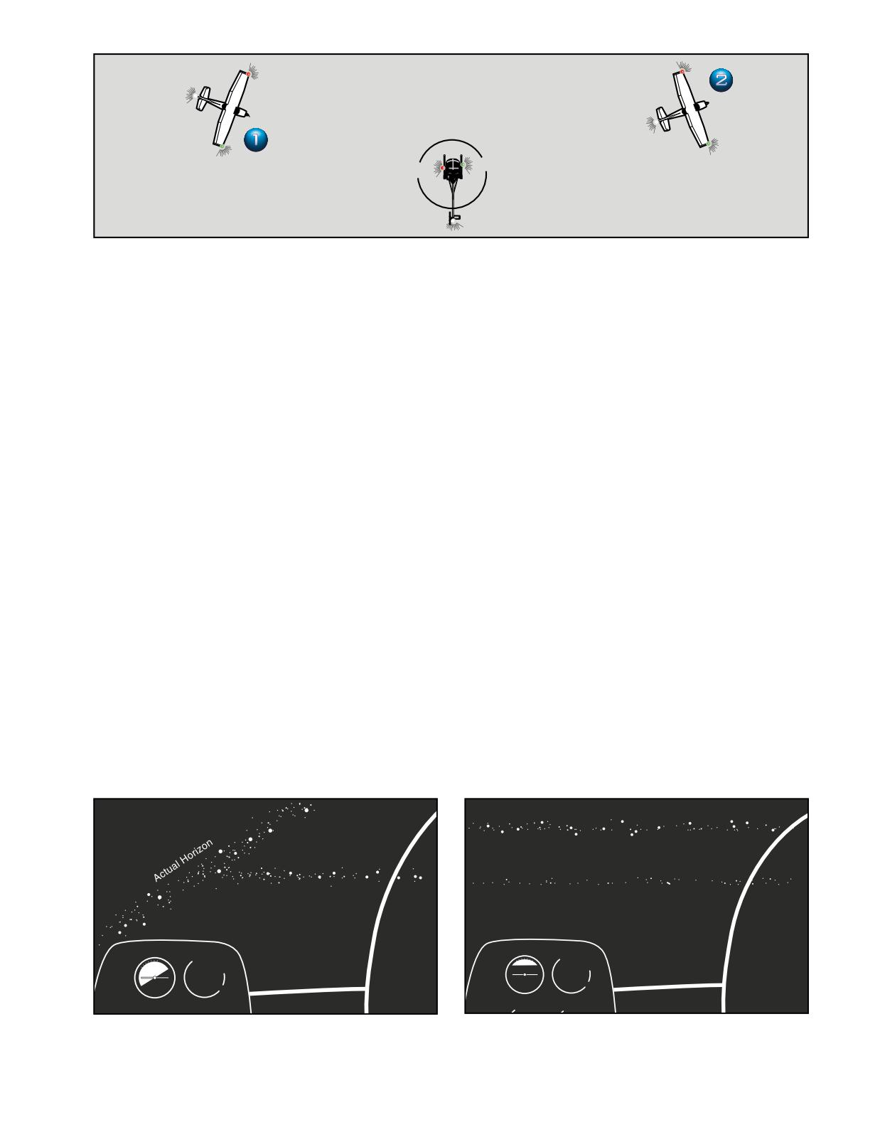
Red
Red
White
White
Green
Green
Green
Red
Your Helicopter
White
Figure 13-5. By interpreting the position lights on other aircraft, you can determine whether the aircraft is flying away from you
or is on a collision course. If you see a red position light to the right of a green light, such as shown by aircraft number 1, it is
flying toward you. You should watch this aircraft closely and be ready to change course. Aircraft number 2, on the other hand,
is flying away from you, as indicated by the white position light.
AIRCRAFT LIGHTING
AUTOKINESIS
In order to see other aircraft more clearly, regulations
Autokinesis is caused by staring at a single point of
require that all aircraft operating during the night hours
light against a dark background, such as a ground light
have special lights and equipment. The requirements
or bright star, for more than a few seconds. After a few
for operating at night are found in Title 14 of the Code
moments, the light appears to move on its own. To pre-
of Federal Regulations (14 CFR) part 91. In addition to
vent this illusion, you should focus your eyes on
aircraft lighting, the regulations also provide a defini-
objects at varying distances and not fixate on one tar-
tion of nighttime, currency requirements, fuel reserves,
get, as well as maintain a normal scan pattern.
and necessary electrical systems.
NIGHT MYOPIA
Position lights enable you to locate another aircraft, as
Another problem associated with night flying is night
well as help you determine its direction of flight. The
myopia, or night-induced nearsightedness. With noth-
approved aircraft lights for night operations are a green
ing to focus on, your eyes automatically focus on a
light on the right cabin side or wingtip, a red light on
point just slightly ahead of your aircraft. Searching out
the left cabin side or wingtip, and a white position light
and focusing on distant light sources, no matter how
on the tail. In addition, flashing aviation red or white
dim, helps prevent the onset of night myopia.
anticollision lights are required for night flights. These
flashing lights can be in a number of locations, but are
most commonly found on the top and bottom of the
FALSE HORIZON
cabin. [Figure 13-5]
A false horizon can occur when the natural horizon is
obscured or not readily apparent. It can be generated by
VISUAL ILLUSIONS
confusing bright stars and city lights. [Figure 13-6] It
There are many different types of visual illusions that
can also occur while you are flying toward the shore of
you can experience at any time, day or night. The next
an ocean or a large lake. Because of the relative darkness
few paragraphs cover some of the illusions that com-
of the water, the lights along the shoreline can be mis-
monly occur at night.
taken for the stars in the sky. [Figure 13-7]
Actual Horizon
Apparent Horizon
Apparent Horizon
Figure 13-6. You can place your helicopter in an extremely
Figure 13-7. In this illusion, the shoreline is mistaken for the
dangerous flight attitude if you align the helicopter with the
horizon. In an attempt to correct for the apparent nose-high
wrong lights. Here, the helicopter is aligned with a road and
attitude, a pilot may lower the collective and attempt to fly
not the horizon.
“beneath the shore.”
13-3
LANDING ILLUSIONS
visually for proper operation. Between sunset and
Landing illusions occur in many forms. Above feature-
sunrise, theses lights must be on any time the engine
less terrain at night, there is a natural tendency to fly a
is running.
lower-than-normal approach. Elements that cause any
type of visual obscuration, such as rain, haze, or a dark
All recently manufactured aircraft certified for night
runway environment also can cause low approaches.
flight, must have an anticollision light that makes the
Bright lights, steep surrounding terrain, and a wide run-
aircraft more visible to other pilots. This light is either
way can produce the illusion of being too low, with a
a red or white flashing light and may be in the form of
tendency to fly a higher-than-normal approach.
a rotating beacon or a strobe. While anticollision lights
are required for night VFR flights, they may be turned
off any time they create a distraction for the pilot.
NIGHT FLIGHT
The night flying environment and the techniques you use
One of the first steps in preparation for night flight is
when flying at night, depend on outside conditions.
becoming thoroughly familiar with the helicopter’s
Flying on a bright, clear, moonlit evening when the visi-
cockpit, instrumentation and control layout. It is rec-
bility is good and the wind is calm, is not much different
ommended that you practice locating each instrument,
from flying during the day. However, if you are flying
control, and switch, both with and without cabin lights.
on an overcast night over a sparsely populated area,
Since the markings on some switches and circuit
with little or no outside lights from the ground, the sit-
breaker panels may be hard to read at night, you should
uation is quite different. Visibility is restricted so you
assure yourself that you are able to locate and use these
have to be more alert in steering clear of obstructions
devices, and read the markings in poor light conditions.
and low clouds. Your options are also limited in the
Before you start the engine, make sure all necessary
event of an emergency, as it is more difficult to find
equipment and supplies needed for the flight, such as
a place to land and determine wind direction and
charts, notepads, and flashlights, are accessible and
speed. At night, you have to rely more heavily on the
ready for use.
aircraft systems, such as lights, flight instruments, and
navigation equipment. As a precaution, if the visibility
is limited or outside references are inadequate, you
ENGINE STARTING AND ROTOR
should strongly consider delaying the flight until con-
ENGAGEMENT
ditions improve, unless you have received training in
Use extra caution when starting the engine and engag-
instrument flight and your helicopter has the appropri-
ing the rotors, especially in dark areas with little or no
ate instrumentation and equipment.
outside lights. In addition to the usual call of “clear,”
turn on the position and anticollision lights. If condi-
tions permit, you might also want to turn the landing
PREFLIGHT
light on momentarily to help warn others that you are
The preflight inspection is performed in the usual man-
about to start the engine and engage the rotors.
ner, except it should be done in a well lit area or with a
flashlight. Careful attention must be paid to the aircraft
electrical system. In helicopters equipped with fuses, a
TAXI TECHNIQUE
spare set is required by regulation, and common sense,
Landing lights usually cast a beam that is narrow and
so make sure they are onboard. If the helicopter is
concentrated ahead of the helicopter, so illumination to
equipped with circuit breakers, check to see that they
the side is minimal. Therefore, you should slow your
are not tripped. A tripped circuit breaker may be an
taxi at night, especially in congested ramp and parking
indication of an equipment malfunction. Reset it and
areas. Some helicopters have a hover light in addition
check the associated equipment for proper operation.
to a landing light, which illuminates a larger area under
the helicopter.
Check all the interior lights, especially the instrument
and panel lights. The panel lighting can usually be con-
When operating at an unfamiliar airport at night, you
trolled with a rheostat or dimmer switch, allowing you
should ask for instructions or advice concerning local
to adjust the intensity. If the lights are too bright, a glare
conditions, so as to avoid taxiing into areas of con-
may reflect off the windshield creating a distraction.
struction, or unlighted, unmarked obstructions. Ground
Always carry a flashlight with fresh batteries to pro-
controllers or UNICOM operators are usually coopera-
vide an alternate source of light if the interior lights
tive in furnishing you with this type of information.
malfunction.
TAKEOFF
All aircraft operating between sunset and sunrise are
Before takeoff, make sure that you have a clear, unob-
required to have operable navigation lights. Turn
structed takeoff path. At airports, you may accomplish
these lights on during the preflight to inspect them
this by taking off over a runway or taxiway, however, if
13-4
you are operating off-airport, you must pay more atten-
time emergency landings. If available, turn on the land-
tion to the surroundings. Obstructions may also be dif-
ing light during the final descent to help in avoiding
ficult to see if you are taking off from an unlighted area.
obstacles along your approach path.
Once you have chosen a suitable takeoff path, select a
point down the takeoff path to use for directional refer-
COLLISION AVOIDANCE AT NIGHT
ence. During a night takeoff, you may notice a lack of
At night, the outside visual references are greatly
reliable outside visual references after you are airborne.
reduced especially when flying over a sparsely popu-
This is particularly true at small airports and off-airport
lated area with little or no lights. The result is that you
landing sites located in sparsely populated areas. To
tend to focus on a single point or instrument, making
compensate for the lack of outside references, use the
you less aware of the other traffic around. You must
available flight instruments as an aid. Check the altime-
make a special effort to devote enough time to scan for
ter and the airspeed indicator to verify the proper climb
traffic. You can determine another aircraft’s direction
attitude. An attitude indicator, if installed, can enhance
of flight by interpreting the position and anticollision
your attitude reference.
lights.
The first 500 feet of altitude after takeoff is considered
APPROACH AND LANDING
to be the most critical period in transitioning from the
Night approaches and landings do have some advan-
comparatively well-lighted airport or heliport into
tages over daytime approaches, as the air is generally
what sometimes appears to be total darkness. A takeoff
smoother and the disruptive effects of turbulence and
at night is usually an “altitude over airspeed” maneu-
excessive crosswinds are often absent. However, there
ver, meaning you will most likely perform a nearly
are a few special considerations and techniques that
maximum performance takeoff. This improves the
apply to approaches at night. For example, when land-
chances for obstacle clearance and enhances safety.
ing at night, especially at an unfamiliar airport, make
When performing this maneuver, be sure to avoid the
the approach to a lighted runway and then use the taxi-
cross-hatched or shaded areas of the height-velocity
ways to avoid unlighted obstructions or equipment.
diagram.
Carefully controlled studies have revealed that pilots
EN ROUTE PROCEDURES
have a tendency to make lower approaches at night
In order to provide a higher margin of safety, it is rec-
than during the day. This is potentially dangerous as
ommended that you select a cruising altitude somewhat
you have a greater chance of hitting an obstacle, such
higher than normal. There are several reasons for this.
as an overhead wire or fence, which are difficult to see.
First, a higher altitude gives you more clearance
It is good practice to make steeper approaches at night,
between obstacles, especially those that are difficult to
thus increasing any obstacle clearance. Monitor your
see at night, such as high tension wires and unlighted
altitude and rate of descent using the altimeter.
towers. Secondly, in the event of an engine failure, you
have more time to set up for a landing and the gliding
distance is greater giving you more options in making a
Another tendency is to focus too much on the landing
safe landing. Thirdly, radio reception is improved, par-
area and not pay enough attention to airspeed. If too
ticularly if you are using radio aids for navigation.
much airspeed is lost, a settling-with-power condition
may result. Maintain the proper attitude during the
During your preflight planning, it is recommended that
approach, and make sure you keep some forward air-
you select a route of flight that keeps you within reach
speed and movement until close to the ground. Outside
of an airport, or any safe landing site, as much of the
visual reference for airspeed and rate of closure may
time as possible. It is also recommended that you fly as
not be available, especially when landing in an
close as possible to a populated or lighted area such as
unlighted area, so pay special attention to the airspeed
a highway or town. Not only does this offer more
indicator
options in the event of an emergency, but also makes
navigation a lot easier. A course comprised of a series
Although the landing light is a helpful aid when mak-
of slight zig-zags to stay close to suitable landing sites
ing night approaches, there is an inherent disadvantage.
and well lighted areas, only adds a little more time and
The portion of the landing area illuminated by the land-
distance to an otherwise straight course.
ing light seems higher than the dark area surrounding
it. This effect can cause you to terminate the approach
In the event that you have to make a forced landing at
at too high an altitude, resulting in a settling-with-
night, use the same procedure recommended for day-
power condition and a hard landing.
13-5
13-6
Aeronautical decision making (ADM) is a systematic
A helicopter pilot, with limited experience flying in
approach to the mental process used by pilots to con-
adverse weather, wants to be back at his home airport
sistently determine the best course of action in response
in time to attend an important social affair. He is
to a given set of circumstances. The importance of
already 30 minutes late. Therefore, he decides not to
learning effective ADM skills cannot be overempha-
refuel his helicopter, since he should get back home
sized. While progress is continually being made in the
with at least 20 minutes of reserve. In addition, in spite
advancement of pilot training methods, aircraft equip-
of his inexperience, he decides to fly through an area of
ment and systems, and services for pilots, accidents
possible thunderstorms in order to get back just before
still occur. Despite all the changes in technology to
dark. Arriving in the thunderstorm area, he encounters
improve flight safety, one factor remains the
lightning, turbulence, and heavy clouds. Night is
same-the human factor. It is estimated that approxi-
approaching, and the thick cloud cover makes it very
mately 65 percent of the total rotorcraft accidents are
dark. With his limited fuel supply, he is not able to cir-
human factors related.
cumnavigate the thunderstorms. In the darkness and
turbulence, the pilot becomes spatially disoriented
Historically, the term “pilot error” has been used to
while attempting to continue flying with visual refer-
describe the causes of these accidents. Pilot error
ence to the ground instead of using what instruments
means that an action or decision made by the pilot was
he has to make a 180° turn. In the ensuing crash, the
the cause of, or a contributing factor that lead to, the
pilot is seriously injured and the helicopter completely
accident. This definition also includes the pilot’s fail-
destroyed.
ure to make a decision or take action. From a broader
perspective, the phrase “human factors related” more
By discussing the events that led to this accident, we
aptly describes these accidents since it is usually not a
can understand how a series of judgmental errors
single decision that leads to an accident, but a chain of
contributed to the final outcome of this flight. For
events triggered by a number of factors.
example, one of the first elements that affected the
pilot’s flight was a decision regarding the weather. The
The poor judgment chain, sometimes referred to as the
pilot knew there were going to be thunderstorms in the
“error chain,” is a term used to describe this concept of
area, but he had flown near thunderstorms before and
contributing factors in a human factors related acci-
never had an accident.
dent. Breaking one link in the chain normally is all that
is necessary to change the outcome of the sequence of
Next, he let his desire to arrive at his destination on
events. The following is an example of the type of sce-
time override his concern for a safe flight. For one
nario illustrating the poor judgment chain.
thing, in order to save time, he did not refuel the heli-
copter, which might have allowed him the opportunity
to circumnavigate the bad weather. Then he overesti-
mated his flying abilities and decided to use a route that
took him through a potential area of thunderstorm
activity. Next, the pilot pressed on into obviously dete-
Human Factors-The study of how
riorating conditions instead of changing course or
people interact with their environ-
ments. In the case of general avia-
landing prior to his destination.
tion, it is the study of how pilot
performance is influenced by such
issues as the design of cockpits, the
On numerous occasions during the flight, the pilot
function of the organs of the body,
could have made effective decisions that may have pre-
the effects of emotions, and the
interaction and communication
vented this accident. However, as the chain of events
with the other participants of the
unfolded, each poor decision left him with fewer and
aviation community, such as other
fewer options. Making sound decisions is the key to
crew members and air traffic con-
trol personnel.
preventing accidents. Traditional pilot training has
14-1
emphasized flying skills, knowledge of the aircraft, and
to: ground personnel, dispatchers, cabin crewmembers,
familiarity with regulations. ADM training focuses on
maintenance personnel, external-load riggers, and air
the decision-making process and the factors that affect
traffic controllers. Although the CRM concept origi-
a pilot’s ability to make effective choices.
nated as airlines developed ways of facilitating crew
cooperation to improve decision making in the cockpit,
ORIGINS OF ADM TRAINING
CRM principles, such as workload management, situa-
The airlines developed some of the first training pro-
tional awareness, communication, the leadership role
grams that focused on improving aeronautical decision
of the captain, and crewmember coordination have
making. Human factors-related accidents motivated the
direct application to the general aviation cockpit. This
airline industry to implement crew resource manage-
also includes single pilot operations since pilots of
ment (CRM) training for flight crews. The focus of
small aircraft, as well as crews of larger aircraft, must
CRM programs is the effective use of all available
make effective use of all available resources-human
resources; human resources, hardware, and informa-
resources, hardware, and information. You can also
tion. Human resources include all groups routinely
refer to AC 60-22, Aeronautical Decision Making,
working with the cockpit crew (or pilot) who are
which provides background references, definitions, and
involved in decisions that are required to operate a
other pertinent information about ADM training in the
flight safely. These groups include, but are not limited
general aviation environment. [Figure 14-1]
DEFINITIONS
ADM is a systematic approach to the mental process used by pilots to consistently determine the best course of action in
response to a given set of circumstances.
ATTITUDE is a personal motivational predisposition to respond to persons, situations, or events in a given manner that can,
nevertheless, be changed or modified through training as sort of a mental shortcut to decision making.
ATTITUDE MANAGEMENT is the ability to recognize hazardous attitudes in oneself and the willingness to modify them as
necessary through the application of an appropriate antidote thought.
CREW RESOURCE MANAGEMENT (CRM) is the application of team management concepts in the flight deck environment. It
was initially known as cockpit resource management, but as CRM programs evolved to include cabin crews, maintenance
personnel, and others, the phrase crew resource management was adopted. This includes single pilots, as in most general
aviation aircraft. Pilots of small aircraft, as well as crews of larger aircraft, must make effective use of all available resources;
human resources, hardware, and information. A current definition includes all groups routinely working with the cockpit crew who
are involved in decisions required to operate a flight safely. These groups include, but are not limited to: pilots, dispatchers, cabin
crewmembers, maintenance personnel, and air traffic controllers. CRM is one way of addressing the challenge of optimizing the
human/machine interface and accompanying interpersonal activities.
HEADWORK is required to accomplish a conscious, rational thought process when making decisions. Good decision making
involves risk identification and assessment, information processing, and problem solving.
JUDGMENT is the mental process of recognizing and analyzing all pertinent information in a particular situation, a rational
evaluation of alternative actions in response to it, and a timely decision on which action to take.
PERSONALITY is the embodiment of personal traits and characteristics of an individual that are set at a very early age and
extremely resistant to change.
POOR JUDGMENT CHAIN is a series of mistakes that may lead to an accident or incident. Two basic principles generally
associated with the creation of a poor judgment chain are: (1) One bad decision often leads to another; and (2) as a string of bad
decisions grows, it reduces the number of subsequent alternatives for continued safe flight. ADM is intended to break the poor
judgment chain before it can cause an accident or incident.
RISK ELEMENTS IN ADM take into consideration the four fundamental risk elements: the pilot, the aircraft, the environment, and
the type of operation that comprise any given aviation situation.
RISK MANAGEMENT is the part of the decision making process which relies on situational awareness, problem recognition, and
good judgment to reduce risks associated with each flight.
SITUATIONAL AWARENESS is the accurate perception and understanding of all the factors and conditions within the four
fundamental risk elements that affect safety before, during, and after the flight.
SKILLS and PROCEDURES are the procedural, psychomotor, and perceptual skills used to control a specific aircraft or its
systems. They are the airmanship abilities that are gained through conventional training, are perfected, and become almost
automatic through experience.
STRESS MANAGEMENT is the personal analysis of the kinds of stress experienced while flying, the application of appropriate
stress assessment tools, and other coping mechanisms.
Figure 14-1. These terms are used in AC 60-22 to explain concepts used in ADM training.
14-2
need to be taken to resolve the situation in the time
THE DECISION-MAKING PROCESS
available. The expected outcome of each possible
An understanding of the decision-making process pro-
action should be considered and the risks assessed
vides you with a foundation for developing ADM
before you decide on a response to the situation.
skills. Some situations, such as engine failures, require
you to respond immediately using established proce-
dures with little time for detailed analysis. Traditionally,
Your first thought was to pull up on the collective and
pilots have been well trained to react to emergencies,
yank back on the cyclic, but after weighing the conse-
but are not as well prepared to make decisions that
quences of possibly losing rotor r.p.m. and not being
require a more reflective response. Typically during a
able to maintain the climb rate sufficiently enough to
flight, you have time to examine any changes that
clear the canyon wall, which is now only a hundred
occur, gather information, and assess risk before reach-
yards away, you realize that your only course is to try
ing a decision. The steps leading to this conclusion
to turn back to the landing zone on the canyon floor.
constitute the decision-making process.
IMPLEMENTING THE DECISION AND
DEFINING THE PROBLEM
EVALUATING THE OUTCOME
Problem definition is the first step in the decision-making
Although a decision may be reached and a course of
process. Defining the problem begins with recognizing
action implemented, the decision-making process is not
that a change has occurred or that an expected change
complete. It is important to think ahead and determine
did not occur. A problem is perceived first by the
how the decision could affect other phases of the flight.
senses, then is distinguished through insight and expe-
As the flight progresses, you must continue to evaluate
rience. These same abilities, as well as an objective
the outcome of the decision to ensure that it is produc-
analysis of all available information, are used to deter-
ing the desired result.
mine the exact nature and severity of the problem.
As you make your turn to the downwind, the airspeed
While doing a hover check after picking up fire fight-
drops nearly to zero, and the helicopter becomes very
ers at the bottom of a canyon, you realize that you are
difficult to control. At this point, you must increase air-
only 20 pounds under maximum gross weight. What
speed in order to maintain translational lift, but since
you failed to realize is that they had stowed some of
the CG is aft of limits, you need to apply more forward
their heaviest gear in the baggage compartment,
cyclic than usual. As you approach the landing zone
which shifted the CG slightly behind the aft limits.
with a high rate of descent, you realize that you are in a
Since weight and balance had never created any
potential settling-with-power situation if you try to
problems for you in the past, you did not bother to cal-
trade airspeed for altitude and lose ETL. Therefore, you
culate CG and power required. You did, however, try
will probably not be able to terminate the approach in a
to estimate it by remembering the figures from earlier
hover. You decide to make as shallow of an approach as
in the morning at the base camp. At a 5,000 foot
possible and perform a run-on landing.
density altitude and maximum gross weight, the per-
formance charts indicated you had plenty of excess
The decision making process normally consists of sev-
power. Unfortunately, the temperature was 93°F and
eral steps before you choose a course of action. To help
the pressure altitude at the pick up point was 6,200
you remember the elements of the decision-making
feet (DA = 9,600 feet). Since there was enough power
process, a six-step model has been developed using the
for the hover check, you felt there was sufficient
acronym “DECIDE.” [Figure 14-2]
power to take off.
Even though the helicopter accelerated slowly during
the takeoff, the distance between the helicopter and the
DECIDE MODEL
ground continued to increase. However, when you
attempted to establish the best rate of climb speed, the
Detect the fact that a change has occurred.
nose wanted to pitch up to a higher than normal atti-
Estimate the need to counter or react to the change.
tude, and you noticed that the helicopter was not gain-
Choose a desirable outcome for the success of the flight.
ing enough altitude in relation to the canyon wall a
Identify actions which could successfully control the change.
couple hundred yards ahead.
Do the necessary action to adapt to the change.
Evaluate the effect of the action.
CHOOSING A COURSE OF ACTION
After the problem has been identified, you must evalu-
Figure 14-2. The DECIDE model can provide a framework for
ate the need to react to it and determine the actions that
effective decision making.
14-3