AMBULANCE SERVICE OF NEW SOUTH WALES EUROCOPTER 145 CABIN STAFF SYLLABI AND TRAINING NOTES (2010) - page 2
Aircraft Description
Loading / Unloading
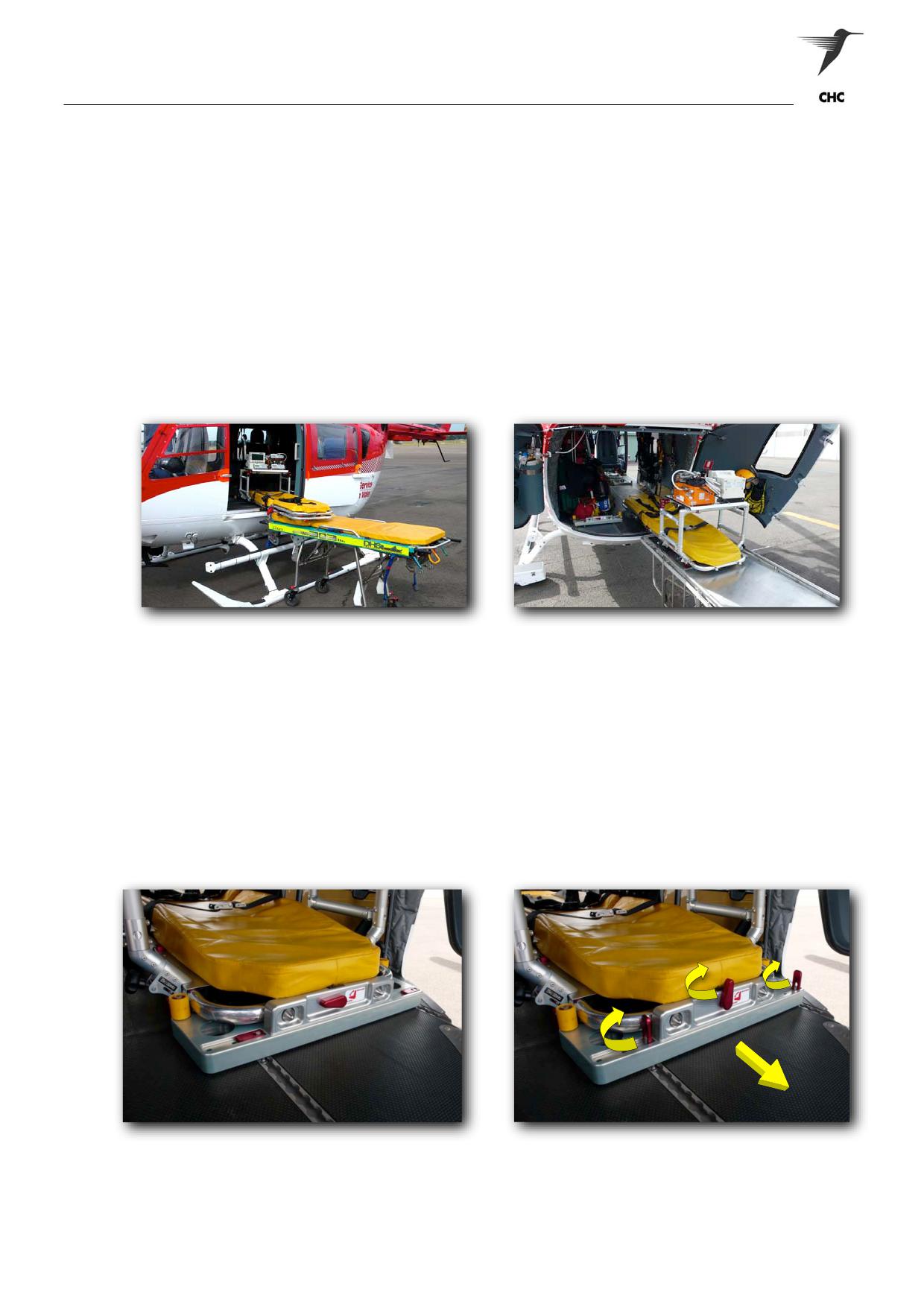
The loading and unloading of the stretcher can be conducted in two methods, where always leaving the
patient’s head orientated forward. The standard practice will be loading from left cabin door with the
patient’s feet entering the cabin first, and unloading occurring from the Clam Shell doors.
Where practical, the second method should be conducted with a suitable height adjustable stretcher,
allowing the patient to be loaded from the Clam Shell doors.
NOTE:
All unloading of patients from the Clam Shell doors should only occur with a suitable height
adjustable stretcher.
In most circumstances, the patient and stretcher will be secured on the RH cabin floor however, if required
the stretcher can be secured to the LH cabin floor; allow a medical crewperson or passenger to utilise the
side-facing fold-down seat (Figure 1-54).
Figure 1-49 Loading from LH Cabin Door
Figure 1-50 Loading / Unloading with a
Height Adjustable Stretcher
Securing Stretcher
To the secure the HeliMods F12, locking plates are utilised at the ‘HEAD’ and ‘FOOT’ positions of the
stretcher, and are intergraded and secure via the cabin floor tracking. When loading form the LH cabin
door, the ‘FOOT’ locking plate must be correctly positioned and secured prior to loading; allowing the
stretcher to a line and engage. Once this has occurred, the corresponding the locking plate can be
positioned and secured.
NOTE:
The reverse sequence applies for loading from the rear, ‘HEAD’ locking plate positioned
and secured.
Figure 1-51 Locking Plate (Locked)
Figure 1-52 Locked Plate (Unlocked)
ASNSW EC145 Cabin Staff Training Notes
Revision 1 - July 2010
page 29 of 34
Aircraft Description
WARNING:
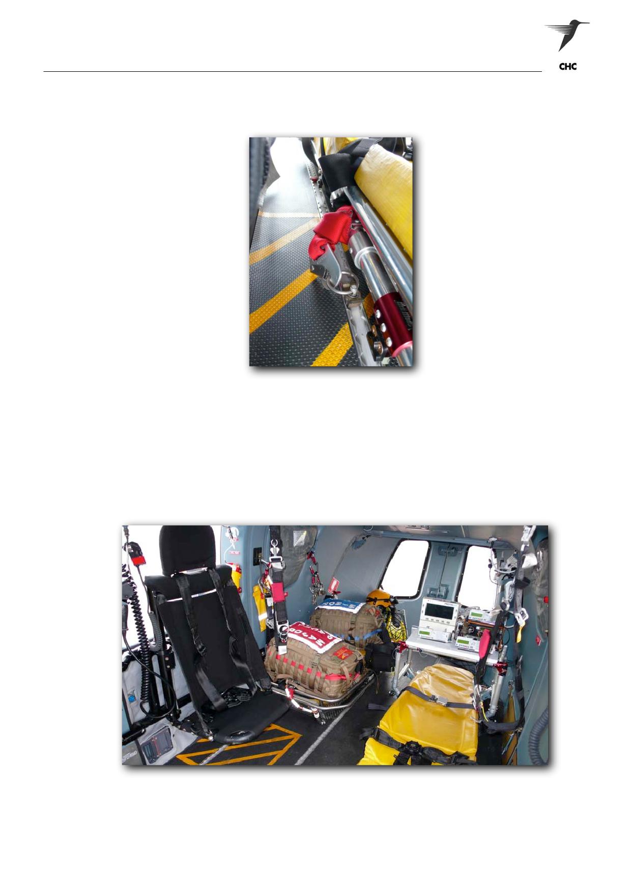
FOR ALL STRETCHER USE, A WEBBING RESTRAINT (NEAR LH FOLDING HINGED)
IS LOOPED AROUND THE STRETCHER CHASSIS AND MUST BE CONNECTED TO
THE FLOOR TRACK VIA A HARD-POINT. (Figure 1-53)
Figure 1-53 Stretcher Restraint
If the stretcher is required on the LH cabin floor, the sequence will remain as per the RH loading
procedures, except the locking plates. The locking plates need to be changed over and positioned so that
the ‘HEAD’ plate is now at the patient’s feet and vice-versa for the ‘FOOT’ plate. This is to allow for the
offset of the stretcher, which is required for stretcher/patient clearances.
Please note, prompt notification to the ACM at the Medical Crew’s request, can allow the ACM to re-
configure the rear cabin to the Medical Crew’s desire, prior to the patient’s arrival to the aircraft.
Figure 1-54 Stretcher Configured the Left-Hand Cabin Wall
ASNSW EC145 Cabin Staff Training Notes
Revision 1 - July 2010
page 30 of 34
Aircraft Description
Dual Patient Configuration
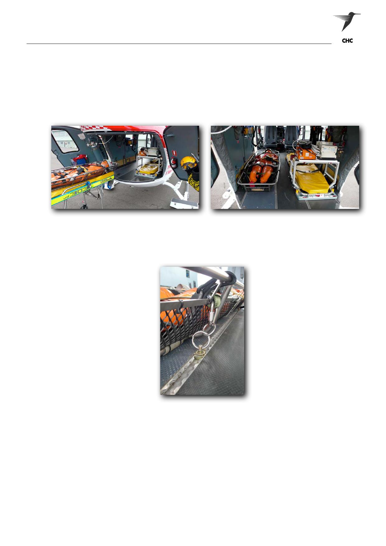
The Medevac II stretcher performs the role of the second stretcher, creating a basic dual patient
configuration and a simple loading procedure. By following the sequence for the HeliMods F12 loading
procedures, the second stretcher will need to be loaded from the Clam Shell doors. (Figure 1-55)
NOTE:
In situations where a height adjustable is not available, other suitable means can be
employed to load the patient from the Clam Shell doors.
Figure 1-55 Loading of the Second Stretcher
Figure 1-56 Dual Patient Configuration
The securing of the second stretcher involves using four dedicated tie-down anchors found in the utility roll
bag, to then be used in conjunction with the ‘Delta’ rapides fitted to the outside corners of the stretcher
chassis. The Delta rapides only need to be screwed finger tight; the anchor points are then fitted and
locked to the floor tracking.
Figure 1-57 Securing of the Second Stretcher
Stretcher Bridge
Fitting to Stretcher
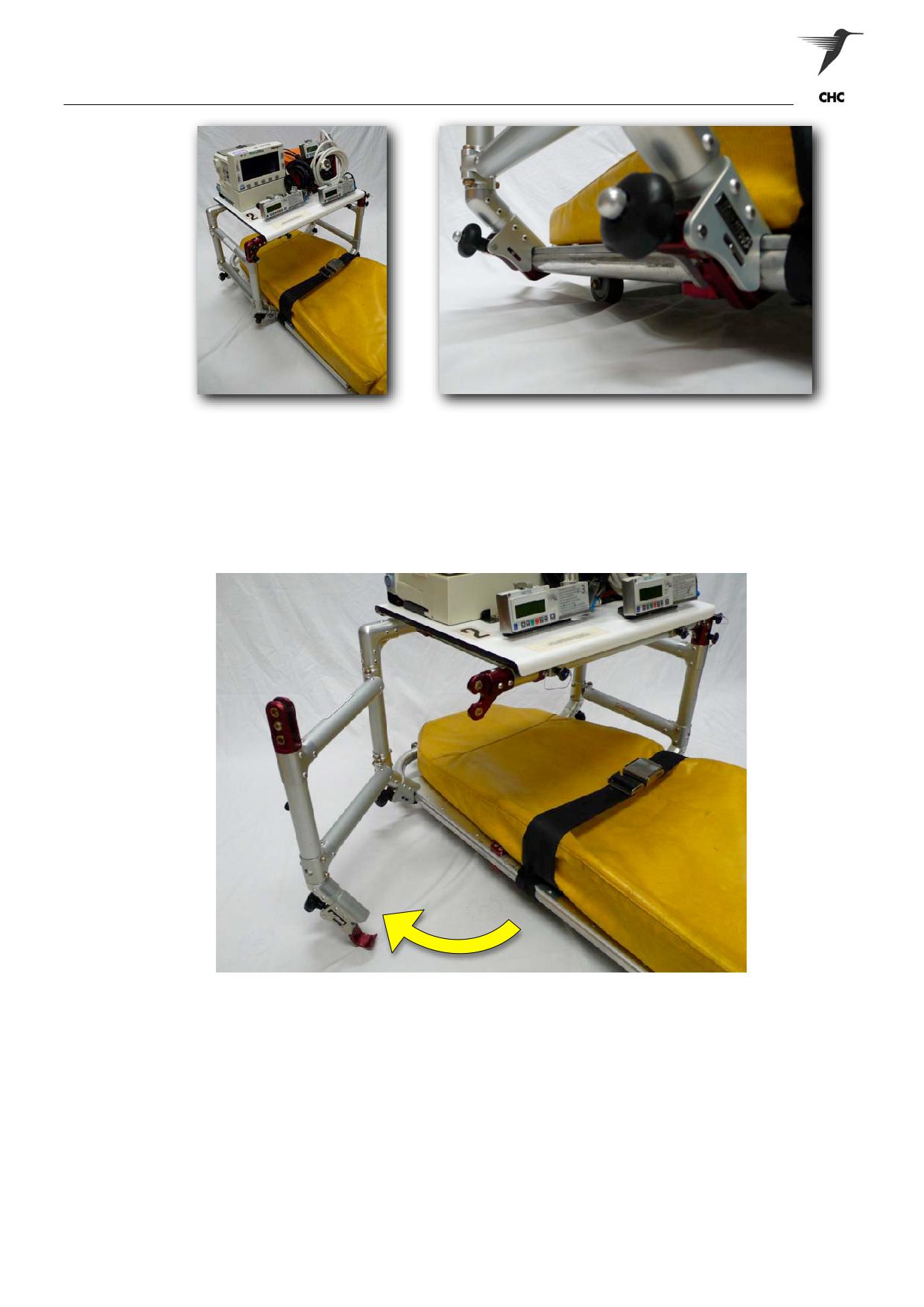
The bridge can be attached to the stretcher by either placing the stretcher on a flat surface or within the
aircraft cabin. The bridge needs to be orientated so the placard on the bridge’s frame corresponds to the
patient’s orientation, and the monitors facing towards the patients head (Fig 1-58). The four stretcher
mounting clamps have threaded tensioning black knobs - these will need loosening prior to the bridge’s
placement on the stretcher, allowing the red anodised hooks to overlap the stretcher chassis. Once the
hooks are in place, the hooks can be clamped tight by turning knob in a clockwise direction. To remove the
bridge from the stretcher it’s simply the reverse procedure.
ASNSW EC145 Cabin Staff Training Notes
Revision 1 - July 2010
page 31 of 34
Aircraft Description
Figure 1-58 Bridge Orientations
Figure 1-59 Stretcher Mounting Clamps
For the ease of patient loading, the bridge has a swing-arm on each side that opens to allow the patient’s
feet to slide across and under the bridge. To open the swing-arm - the top-plate (monitors) needs to
remain fitted to support the bridge’s frame; the next step is to remove the two pit-pins at one of corners of
the frame. Once the pit-pins have been removed, the mounting clamp below needs to be released,
allowing the gate to swing open.
Figure 1-60 Bridge Swing-Arm Gate
Cable & Oxygen Routing
An auxiliary power, medical alert and oxygen outlets have been specifically installed directly above the
bridge for when the stretcher has been configured on the RH cabin floor.
ASNSW EC145 Cabin Staff Training Notes
Revision 1 - July 2010
page 32 of 34
Aircraft Description
Bridge Charging System
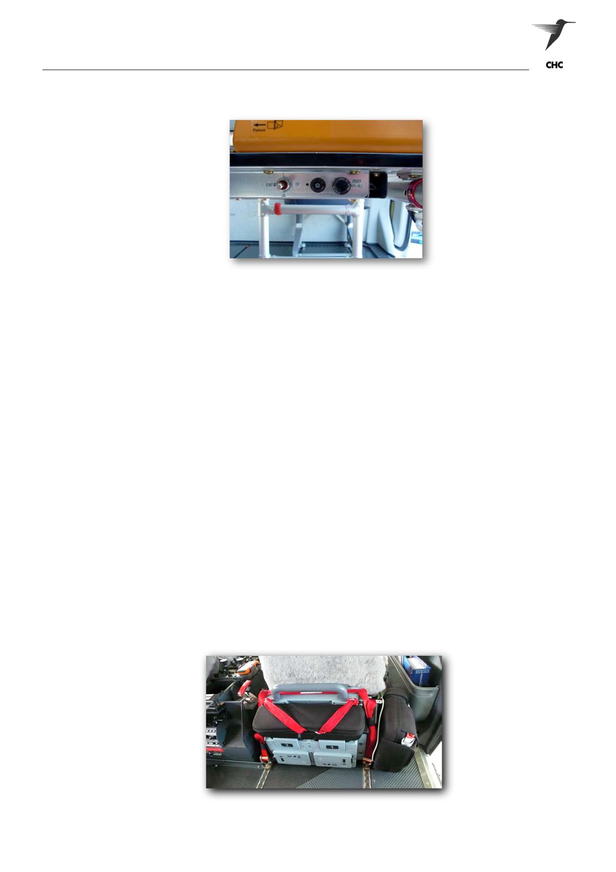
Figure 1-62 Bridge Charging Panel
A charging system has been incorporated in the bridge, allowing the system to be charged in-flight. The
charging panel is located on the Oxylog 2000 side, with panel consisting of a three-way switch (START-
ON-OFF), 10 Amp Circuit Breaker and a Power Available Indicator (Green).
To initialise the charge the unit needs to be plugged in via the charging cable fitted to the bridge. Once
plugged into either the ground’s charging pack or aircraft power supply the charging phase will not be
completed until the three-way switch is selected to ‘Start’, which is a momentary selection to initialise the
charging phase. At the point the charging phase will continue in the ‘ON’ position, to cancel the charge and
remove the plug from the power supply the switch will need to be selected to ‘OFF”. In the event of the
bridge’s circuit breaker trips or an aircraft circuit breaker, the bridge is to be deemed unserviceable, until
serviced by a technician and approved for use.
CAUTION:
The aircraft captain’s permission must be obtained prior to the bridge-charging phase
being initialised. This is to avoid electrical spiking induced during the aircraft’s start-up,
which may cause electrical damage to the bridge’s monitoring equipment.
LIFEPAK 15 (Defibrillator)
When not in use the LIFEPAK 15 is to be stowed on the cabin floor directly behind the RH Pilots seat, and
secured by an approved restraint (Figure 1-63). For all other applications, the device can be secured to the
cabin floor track by utilising the approved restraint.
WARNING:
THE DEFIBRILLATION OF A PATIENT WITHIN THE AIRCRAFT IN-FLIGHT OR ON
THE GROUND MAY ONLY OCCUR WITH THE EXPRESS PERMISSION OF THE
AIRCRAFT CAPTAIN, AS THERE ARE MANY CONSIDERATIONS ANDHAZARDS
THAT MAY CAUSE POTENTIAL RISK TO PERSONNEL AND THE AIRCRAFT.
Figure 1-62 LIFEPAK 15 (Defibrillator) Stowage
ASNSW EC145 Cabin Staff Training Notes
Revision 1 - July 2010
page 33 of 34

Aircraft Description
Lift Raft Stowage
The crews/aircraft Life Raft is to be restrained on the cabin floor directly near the LH cabin door. There is a
dedicated Life Raft restraint that can be located in the RH soft stowage compartment.
Figure 1-63 Life Raft Stowage
ASNSW EC145 Cabin Staff Training Notes
Revision 1 - July 2010
page 34 of 34
Principals of Flight
PRINCIPALS OF FLIGHT
1
Introduction
2
Configurations and Control
3
Hovering and Forward Flights
4
Autorotation
5
Blade Sailing
ASNSW EC145 Cabin Staff Training Notes
Revision 1 - July 2010
page 1 of 5
Principals of Flight
1
INTRODUCTION
The basic rules govern both fixed wing and rotary wing aircraft, and equally both types suffer from the
same problem, that is, the aircraft is heavier than air. To overcome this, an aircraft must produce an
aerodynamic (lifting) force to overcome the weight of the aircraft before it can leave the ground. In both
fixed and rotary wing aircraft this is achieved by the aerodynamic reaction resulting from a flow of air
around an aerofoil section. The main difference is that a fixed wing aircraft, as the name implies, has its
aerofoil section (wings) attached to the fuselage at a fixed angle and position, whilst in the helicopter the
aerofoil has been removed from the fuselage and attached to a centre shaft, which is given a rotational
velocity.
The aerofoil on a helicopter (main rotor) can be made up of two or more blades (wings). These blades that
make up the main rotor are turned by power given out by one or more engine(s). In order for air to flow
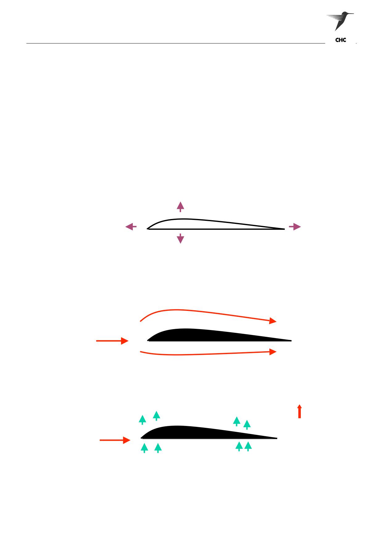
over the aerofoil (figure 2-1) of a fixed wing aircraft that aircraft has to travel fast along the runway before
sufficient aerodynamic lift is produced to overcome the weight and, as a consequence, it leaves the
ground. A helicopter, however, pushes its aerofoil through the air by rotating the main rotor, thus
producing sufficient lift to overcome its weight, allowing the helicopter to take-off vertically.
LIFT
THRUST
DRAG
WEIGHT
Figure 2-1 Aerofoil
FASTER MOVING AIR
AIR
FLOW
SLOWER MOVING AIR
LIFT
LOWER PRESSURE
-
-
-
-
-
Air flow from
AIR
high to low
pressure
+
+
FLOW
+
+
taking the
aerofoil with it
HIGHER PRESSURE
Figure 2-2 Principals of lift
ASNSW EC145 Cabin Staff Training Notes
Revision 1 - July 2010
page 2 of 5
Principals of Flight
2
CONFIGURATION AND CONTROL
Helicopters may be single or multi-rotor, each rotor having several blades, usually varying from two to six in
number. A single rotor helicopter requires some compensating device to overcome “torque reaction”, and
to prevent the aircraft from rotating in the opposite direction to that of the rotor. This consists of a small
vertical tail rotor producing sideways lift (thrust), mounted on a tail cone. By varying this thrust the tail rotor
may also be used to turn the helicopter. In the event of engine(s) failure, helicopter rotor systems include a
freewheeling device to permit free rotation of the rotor.
While the helicopter rotor blade may look different to an aeroplane’s wing, the cross section of the aerofoil
remains substantially the same, and, of course, the same is required of each i.e. to produce LIFT (figure 2-
2).
Vertical Movement
To achieve vertical movement the lift on each blade must be increased by
the same amount. The pitch angle must be increased collectively (on each
blade at the same time) and the ‘COLLECTIVE LEVER’ achieves this. The
reverse takes place in a vertical descent. If you increase the pitch angle
on all the blades it becomes more difficult to push the blade through the air
(increased DRAG) so this manoeuvre requires more power from the
engines, otherwise the blades would slow down.
Horizontal
Horizontal Movement is achieved by tilting the disc in the direction
required. To enable the disc to tilt the pitch angle vary through the blades
360° “cycle” of travel.
This change in pitch is therefore known as the “cyclic” pitch change, and is
achieved by the pilot moving the CYCLIC stick.
Figure 2-3 Horizontal Movement
Torque Reaction
The fuselage will rotate in the opposite direction to the main rotor as a
result of torque reaction. The fitting of a vertical Tail Rotor, which produces
a sideways thrust, will overcome this problem. When the movement of the
tail rotor thrust (lift) equals the torque reaction the helicopter will maintain a
constant direction. The tail rotor typically turns about 5-6 times faster than
the main rotor. The tail rotor has the following additional functions:
-
Alter direction in the hover
-
Maintain a balanced condition of flight
-
Stop the fuselage rotating in power off flight (autorotation)
ASNSW EC145 Cabin Staff Training Notes
Revision 1 - July 2010
page 3 of 5
Principals of Flight
3
HOVERING AND FORWARD FLIGHT
To lift a helicopter off the ground a lifting force must be produced equal and opposite to the weight of the
aircraft, which acts vertically downwards. When the rotor is turning and the collective lever is fully down
very little rotor thrust (lift) is being produced, but as the pitch is increased (collective lever raised) the
blades will begin to produce more lift and eventually the rotor lift will equal the weight. If the pitch is further
increased the rotor lift will exceed the weight and the helicopter will accelerate vertically upwards. Once
clear of the ground the lift is reduced slightly until it is equal to the weight. When this is achieved the
aircraft will hover.
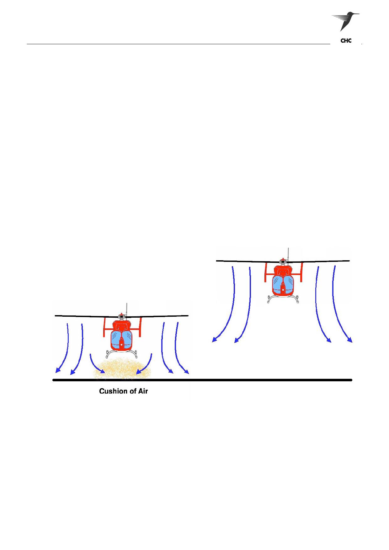
The helicopter when close to the ground uses less power to hover because of the build up of a cushion of
air beneath the aircraft from the flow of air down through the rotor disc (down-wash). The parcel of air
beneath the aircraft when hovering close to the ground, is called the ‘ground cushion or ground effect” (Fig
2-4). When benefiting from using this ground cushion the aircraft is said to be “inside ground effect (IGE)”.
When further away from the ground the downwash dissipates and is of no benefit. The aircraft is then said
to be “outside ground effect” (OGE) and will require more power to hover.
A helicopter hovering close to the ground and benefiting from the ground cushion of air beneath it uses
only some of the down wash in the formation of the ground cushion. The remainder passes outwards from
the helicopter and is dissipated against the surrounding air. This outward flow of air is very strong, being
stronger the closer you are to the aircraft, and can easily lift loose articles and cause damage to persons
and property.
Figure 2-4 Ground Cushion / Ground Effect
ASNSW EC145 Cabin Staff Training Notes
Revision 1 - July 2010
page 4 of 5
Principals of Flight
Forward Flight
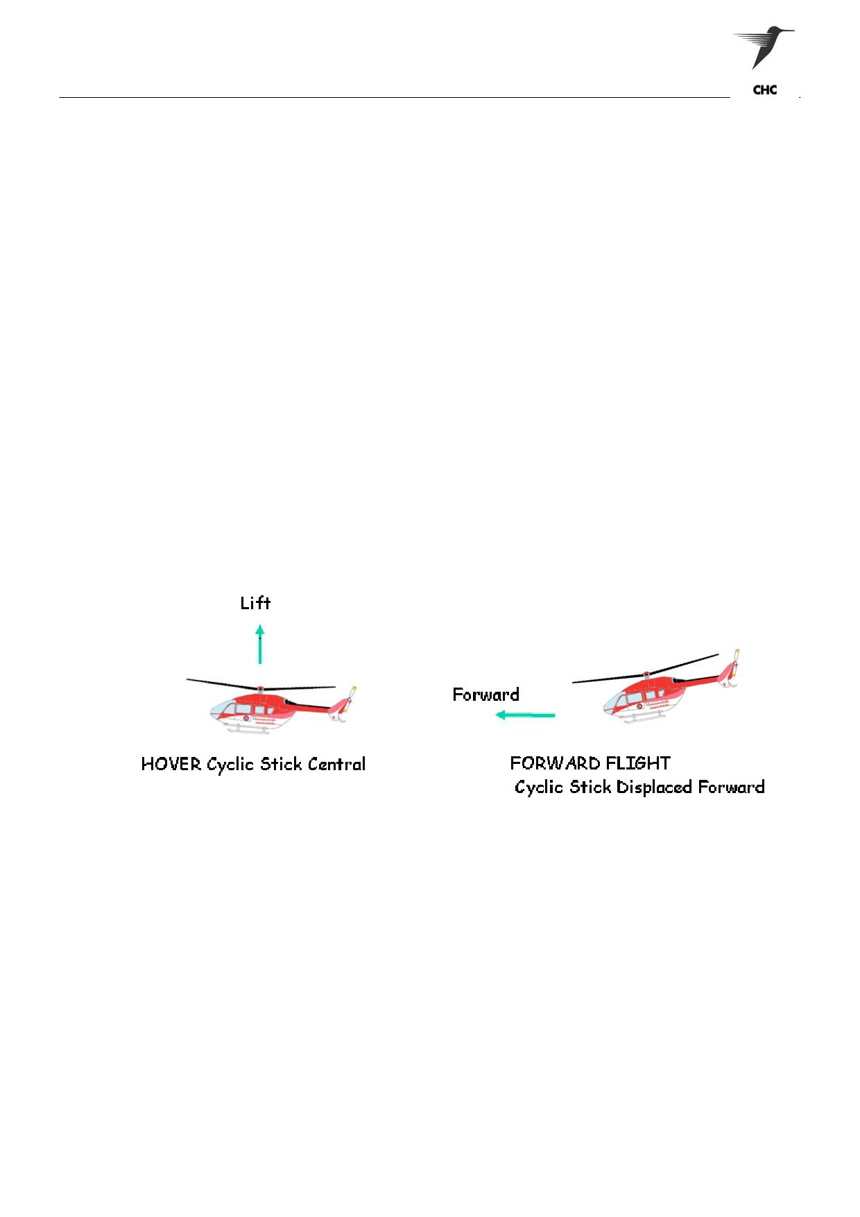
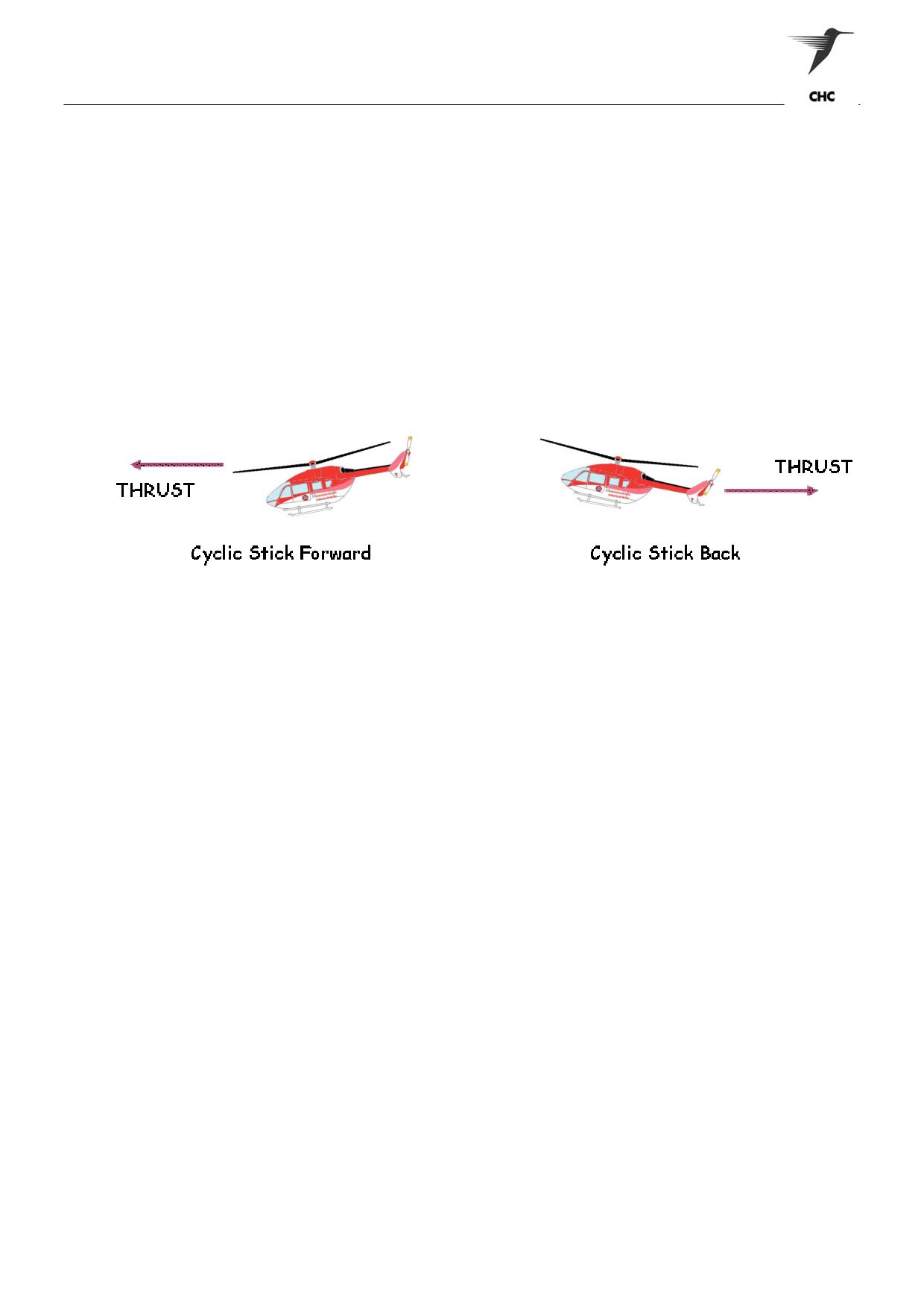
To achieve forward flight from the hover the rotor disc is tilted forward. The change in state from a hover to
movement in a horizontal direction is known as “TRANSITION” (Fig 2-5), the same term being used to
describe a change from horizontal flight back to the hover.
To transition into forward flight the lift has to be increased to cater for this horizontal force. To meet this
requirement the collective lever has to be raised to increase the pitch on the blades. Additionally, there
must be sufficient spare power from the engine to allow for this increase. This is also the case the faster
the forward speed.
The general method of coming to the hover from forward flight is to execute a “flare’. Tilting the disc in the
opposite direction to that of which the helicopter is already moving will achieve this
Figure 2-5 Transition
4
AUTOROTATION
In powered flight the rotor drag is overcome with engine power, but when the engine(s) fails some other
force must be used to maintain the rotor RPM. This is achieved by allowing the helicopter to descend so
that the airflow from beneath strikes the blades in such a manner that the airflow itself provides the driving
force. When the helicopter is descending in this manner the rate of descent becomes the power equivalent
and the helicopter is said to be in a state of ‘autorotation”. An airflow force (auto-rotative force) overcomes
drag on a majority of the blade, and consequently permits the rotor RPM to be retained. This assumes that
the collective lever is fully down. If the collective lever is raised (pitch increased) induced drag will increase
and as there is no engine(s) to provide power to overcome drag, the rotor RPM will decrease. If the RPM
decreases below safe limits, the blades will no longer produce lift.
For multi-engine helicopters, the loss of one engine presents no real problem unless heavy. The helicopter
is still capable of level flight and climbing, although reduced, and more than likely will be unable to hover,
resulting in a running landing. For multi-engine helicopters, an autorotation is required if both engines have
failed or been shut down.
The flare effect at the bottom of an autorotation does exactly the same as the flare with power on, and is
most necessary to the “engines off landing”.
5
BLADE SAILING
Blade Sailing can occur when the rotor is starting up or slowing down in strong wind conditions, particularly
if the wind is gusting. With the helicopter facing into wind (normal practice) the advancing blade
experiences an increase in lift and will flap up excessively due to the low centrifugal force, reaching its
maximum height to the front of the helicopter. The opposite occurs on the retreating side, reaching its
lowest position at the rear of the helicopter i.e. over the tail cone. To control blade sailing it is sometimes
helpful to turn the aircraft out of wind a small amount so that the lowest blade position is not over the tail. It
is also of use to start-up and shutdown the blades as quickly as possible to reduce the time a low rotor.
ASNSW EC145 Cabin Staff Training Notes
Revision 1 - July 2010
page 5 of 5
Operations - General
OPERATIONS - GENERAL
1
Introduction
2
Aircraft Cleanliness
3
Refuelling Procedures
4
Fire Procedures
5
Smoking near Aircraft
6
Use of Mobile Phones and Portable Electronic Audio Devices
ASNSW EC145 Cabin Staff Training Notes
Revision 1 - July 2010
page 1 of 6
Operations - General
1
INTRODUCTION
The readiness of the aircraft and associated role equipment for SAR/EMS operations is the responsibility of
all crew / team members. The standard of preparation and presentation of the aircraft is a direct
representation of the professionalism of those who operate it.
Aircraft refuelling is also a crew responsibility and all concerned must adhere to certain procedures in an
effort to ensure the task is executed correctly and safety.
2
AIRCRAFT CLEANLINESS
A rule of thumb regarding the aircraft’s cleanliness is “always leave it in the same state as you would wish
to find it”.
The crewman’s particular area of responsibility is that of the rear cabin and equipment stowage areas.
Particular attention should be paid to:
a
General cleanliness of the rear cabin area including windows
b
Maintenance of safe blood management
c
Correct and secure stowage of equipment
d
Removal of all unnecessary items
In summary the aircraft is your work place, and as such should be kept neat and clean in an effort to
ensuring a safer working environment.
3
REFUELLING PROCEDURES
Today’s helicopters have gas turbine engines and the fuel required is the same as that used by large jet
aircraft. The designations for the fuel is JETA1 or NATO F34, 40 & 44 and this will normally be secured
from airfield based tankers, on site drum stocks on pre-positioned drum stocks at designated landing sites.
The overall responsibility for aircraft refuelling is that of the captain, however all members of the crew are
to be conversant with the necessary procedures and requirements such as:
a
Hand pump operation
b
Aircraft earthing requirements
c
Actions in the event of fire
Refuelling with Passengers on Board
Only non-ambulatory passengers may remain on board during refuelling operations, provided:
a
The “No Smoking” signs and emergency exit signs are illuminated
b
The passengers are advised that fuelling is to take place, instructed not to smoke, operate
electrical switches or otherwise produce ignition hazards, and informed of the location of the
emergency exits
c
Exit doors on the opposite side of the aircraft to the refuelling point should be open and
unobstructed
d
The aircraft and fuelling equipment are connected to a suitable earth point
e
The refuelling shall be supervised by a competent person to ensure a safe operation
f
Fire extinguishers should be manned and close at hand
ASNSW EC145 Cabin Staff Training Notes
Revision 1 - July 2010
page 2 of 6
Operations - General
Hot Refuelling
Hot refuelling means the refuelling of a helicopter with its engines running. This may be completed with
rotors stationary or turning.
The practice of Hot Refuelling is not available unless the ground personnel are conversant with the
operation and adequate external supervision is available. This would normally preclude the availability of
Hot Refuelling at any location where direct control or regular practice of the procedure cannot be
conducted.
Hot refuelling may be undertaken in the following situations:
a
Search and Rescue (SAR) operations where normal refuelling may jeopardise individual safety or
property
b
Emergency Medical Service (EMS) operations where time is critical in a situation response or
patient transfer
c
Aerial Fire fighting
d
Offshore Operations
e
Operations where stopping the engines or rotors may expose personnel to increased risk or the
efficiency of the operation may be significantly degraded.
Hot refuelling with passengers embarked should only be carried out when, on medical advice, passengers
cannot be safely disembarked.
The Aircraft Captain or a pilot endorsed on type must remain at the helicopter controls while refuelling is
carried out. Communication between the pilot at the controls and the person in charge of the refuelling
operation must be maintained by radio or visual contact and an agreed system of signals.
At least 2 fire extinguishers must be accessible throughout the operation.
During refuelling operations, radio transmissions shall be restricted to safety messages and neither the HF
transmitter nor radar equipment should be operated. All doors and windows must remain closed on the
refuelling side during operation.
Note: A minimum of three persons must be available to assist in patient evacuation should it be required
during Hot Refuelling operations.
4
FIRE PROCEDURES
Introduction
The first priority in a fire situation must be to contain the fire and cut off the fuel supply. A helicopter has
very little sheltered ground beneath the airframe. This factor and the position of the engines and the fuel
tanks in close proximity to the cabin allow fire-fighting efforts to be concentrated and portable fire fighting
equipment to be effective. Portable equipment such as BCF, Carbon dioxide, Halon and Dry powder are
excellent for internal fires.
BCF and Carbon dioxide deplete the air of oxygen therefore care must be taken when used in confined
spaces and the space must be ventilated as soon as possible. Dry powder can damage electrical
equipment and reduce visibility.
ASNSW EC145 Cabin Staff Training Notes
Revision 1 - July 2010
page 3 of 6
Operations - General
Extinguisher Classification and Rating
Portable fire extinguishers are divided into categories by contents and are colour coded accordingly:
Contents
Colour
Class
Water type extinguishers
Red
A
Foam type extinguishers
Blue
AB
Dry powder type extinguisher
Red with White Band
B (E)
Carbon dioxide type extinguishers
Red with Black Band
B (E)
Wet chemical
Buff
A
Bromochlorodifluromethane (BCF)
Yellow
AB (E)
Halon
Red or White
AB (E)
A CLASSIFICATION is given to each extinguisher on the basis of which classes of fire they are capable of
controlling.
Classes
Fires Involving
A
Carbonaceous solids, e.g. wood, paper, textiles etc
B
Flammable liquids
C
Flammable gas
D
Flammable metals
Electrical hazards (not a class)
Extinguishers are rated A or B and in addition have an (E) if the contents are electrically non-conductive.
There is no Australian Standard for class C and D fires, and specialist advice depending on the nature of
the risk should be sought.
Not all extinguishers are suitable for all types of fires
Class (of fire)
Type of Extinguisher
(In order of preference)
A
Water, Wet Chemical, Foam, BCF
B
Foam, Dry Powder, Wet Chemical, BCF, Halon, Carbon Dioxide
C
Specialist advice required. Dry Powder can be used safely.
D
Specialist advice required.
Electrical Hazards (E)
Carbon Dioxide, BCF, Halon, Dry Powder.
Extinguisher Checks
Prior to use all extinguishers must be checked to ensure they are serviceable. All extinguishers must have
a current Inspection Tag; all pressure gauges must indicate in the green, BCF and Dry Powder
extinguishers must have their red disk, located at the rear of the handle.
Extinguisher Use
All portable extinguishers are designed to be used upright by pulling the locking pin out, squeezing the
trigger and aiming at the base of the fire.
Large carbon dioxide extinguishers are operated by ensuring the discharge control nozzle on the handle is
closed, pull the pin and open the operating handle (on the bottle), open discharge nozzle, stand 2 meters
from fire and aim at the base of fire.
ASNSW EC145 Cabin Staff Training Notes
Revision 1 - July 2010
page 4 of 6
Operations - General
Fire Fighting Considerations
Consideration should be given to the following:
1.
Flashbacks may occur after the fire has been extinguished
2.
The upwind side of the fire permits the closest approach and the best rescue path
3.
Discharge extinguishing agents at high output rates to quickly extinguish flames
4.
If only portable extinguishers are available, try to conserve enough of the extinguishing agent to
be able to deal with flashbacks
5.
Concentrate on the upwind side of the cockpit and cabin areas
Location of Extinguishers
The fire extinguishers are located at the left side of pilot seat, and one mounted on the internal left Clam
Shell door.
Fire During Re-fuelling.
Dry chemical powder and/or foam should be used. Dry powder is rapidly effective particularly for small
leaks of ignited fuel but flashback may occur if the fuel is not covered with a blanket of foam. The foam
blanket should be maintained throughout any rescue operation if required.
Aircraft Fires
1.
Engine Fire
These are fires contained within the engine cowling and may include transmission components. They are
most effectively extinguished by the use of the helicopters fire protection system for the engine
compartment operated manually from the cockpit. A common extinguishing agent used in the fire
protection systems is freon and nitrogen stored under pressure (approximately 600 PSI). This agent is
used because of its non-corrosive properties.
WARNING:
THE FLIGHT CREW MUST BE INFORMED IMMEDIATELY THAT AN ENGINE FIRE
EXISTS BY MEANS OF THE ICS OR MARSHALLING SIGNALS.
CAUTION:
Normally, the pilot can extinguish the fire by using the internal fire fighting system.
Applying carbon dioxide (from a portable extinguisher), which forms dry ice crystals, CAN
damage the turbine blades.
2.
Cockpit/Cabin Fire
Most cockpit/cabin fires will be electrical with smoke filling the cockpit/cabin from the burning cable
insulation. Evacuate personnel before ensuring the cockpit/cabin is adequately ventilated and extinguish
the fire using carbon dioxide extinguishers. This extinguishing agent will cause minimum damage to the
instrument panel. BCF may also be used.
3.
Control Panel Fire
Shutting down the electrical circuits, if possible, may reduce or stop the fire. Applying carbon dioxide or
BCF creates hazards for personnel. Evacuate the enclosure.
ASNSW EC145 Cabin Staff Training Notes
Revision 1 - July 2010
page 5 of 6
Operations - General
5
SMOKING NEAR AIRCRAFT
Smoking is prohibited in any Company aircraft. Furthermore, a person shall not smoke whilst within 15
metres of an aircraft.
6
USE OF MOBILE PHONES AND PORTABLE ELECTRONIC DEVICES
The use of mobile phones in aircraft is prohibited unless they have been installed in accordance with the
applicable airworthiness requirement.
The use of hand held units is prohibited.
The use of portable electronic audio devices by crew and passengers is prohibited during all stages of
flight. These devices include personal tape, CD, DVD, MP3 players and iPods. These devices, if operated
in flight, may cause the user to either not hear, or misinterpret any operational or safety announcements.
These devices may also effect the aircraft navigation equipment during critical stages of flight.
ASNSW EC145 Cabin Staff Training Notes
Revision 1 - July 2010
page 6 of 6
Emergency Procedures
EMERGENCY PROCEDURES
1
Introduction
2
Distress and Urgency Calls
3
Forced Landing Procedures
4
Ditching Procedures
5
Aircraft Emergency Locator Transmitter (ELT)
ASNSW EC145 Cabin Staff Training Notes
Revision 1 - July 2010
page 1 of 5
Emergency Procedures
1
INTRODUCTION
Emergency situations can occur in the aviation industry and these can be of a minor or major nature.
Aircrew are trained in the necessary procedures and actions to ensure the safety of the aircraft and crew.
The crewman can assist the pilot in a number of ways during an emergency situation such as:
a
Pin pointing the aircraft’s position
b
Transmitting a distress message
c
Identification of a suitable forced landing area
d
Securing the rear cabin
e
Ensuring passengers are secure and aware of the situation
2
DISTRESS AND URGENCY CALLS
DISTRESS
When a pilot considers that the aircraft is being threatened by grave or imminent danger (and requires
immediate assistance) he shall transmit a distress (May Day) Call.
The following signals, used either together or separately, indicate a distress situation:
a
A signal made by radio or by any other signalling method consisting of the group
... --- ... (SOS) in the Morse Code.
b
A signal sent by radio consisting of the spoken word “Mayday”.
c
Rockets or shells throwing red lights, fired one at a time at short intervals.
d
A parachute flare showing a red light.
e
Emergency SSR Codes (Emergency 7700, Radio Failure 7600, Hijack 7500).
The radio call shall contain:
MAYDAY (3 TIMES)
Aircraft Call Sign (3 times)
Position and Time
Heading
Airspeed
Altitude
Aircraft Type
Nature of Distress
Captain’s Intentions
Any other information that may facilitate the rescue
Emergency Frequencies
121.5 MHz
243.0 MHz
406.0 MHz
156.8 MHz (Marine Channel 16)
ASNSW EC145 Cabin Staff Training Notes
Revision 1 - July 2010
page 2 of 5
Emergency Procedures
URGENCY
An urgency message shall be sent when a condition exists affecting the safety of an aircraft or other
vessel, or of some person on board or within sight, but which does not require immediate assistance.
Should any situation develop where a diversion must be made during the flight, the Air Traffic Service are
to be advised by the transmission of a PAN message.
The following signals used either together or separately indicate an urgent situation:
a
A signal made by radio telegraphy or any other signalling method consisting of the group XXX
b
A signal sent by radio telephone consisting of the spoken words "PAN PAN"
c
The repeated switching on and off of the landing lights.
The repeated switching on and off of the navigation lights
The radio call shall contain:
PAN PAN (3 times)
Call-sign of a specific station or "ALL STATIONS"
Aircraft Call-sign
Request for bearing, course or position (if required)
Position and Time
Heading
Airspeed
Altitude
Aircraft Type
Available flight time
Nature of emergency
Captain's intentions
3
FORCED LANDING PROCEDURES
If an emergency situation arises which requires the aircraft to land immediately you are to acknowledge
that you are aware of the situation and then secure the rear cabin ensuring all passengers and yourself
are seated and secure.
If time permits you can assist the pilot by identifying a suitable landing area if visible and informing him of
its position by means of the clock code and distance. Also you may be required to transmit a distress
message if the flying pilot is unable to do so.
If a forced landing is imminent the flying pilot will call 'BRACE BRACE BRACE", all personnel are to
adopt the brace position (Fig 4-1).
a
Forward facing seat - Lap Seat Belt
Lower the head onto the left arm and bend forward from the waist. The left arm and head may
be rested on the back of the seat in front of you.
b
All other seat positions - Lap Seat Belt/All Seat Positions - Full Harness Belt
Sit upright, with your head against any headrest. Protect your face by raising the left elbow.
Figure 4-1 Brace Position
ASNSW EC145 Cabin Staff Training Notes
Revision 1 - July 2010
page 3 of 5
Emergency Procedures
Following a forced landing, personnel should remain secured until all movement has ceased (rotor
blades) and then make their way clear when it is safe to do so.
If there are signs of fire, personnel should exit the aircraft immediately; however be aware that the rotor
blades could still be turning, and possibly closer to the ground due to skid / undercarriage collapse.
As a member of the crew, you are responsible for assisting passengers where necessary.
4
DITCHING PROCEDURES
The responsibilities of the crewman for an emergency situation over water are the same as those for over
land.
If an emergency situation arises and a ditching is imminent the flying pilot will call "BRACE BRACE
BRACE", all personnel are to adopt the brace position so detailed above while at the same time
identifying their nearest exit and a secondary exit should the first be obstructed.
Once the aircraft has settled on the water and all movement has ceased, personnel should exit the
aircraft and inflate their life vest only when well clear. The crewman is to deploy and inflate the aircraft
fitted life raft and, along with the aircraft captain, ensure all personnel are accounted for and the
necessary Emergency Locator Transmitter is activated.
5
AIRCRAFT EMERGENCY LOCATOR TRANSMITTER (ELT)
Introduction
The Emergency Locator Transmitter system is designed for installation in helicopters and fixed wing
aircraft. The purpose is to provide the localisation of the aircraft after a crash or an emergency landing.
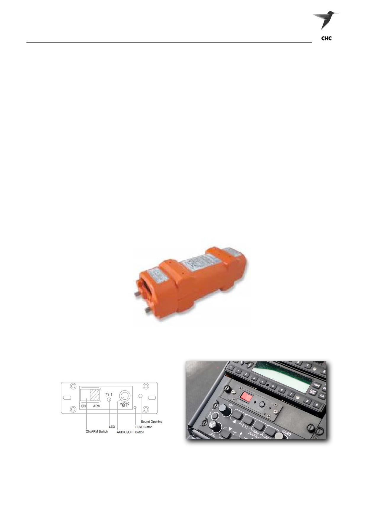
The system consists of:
• An Emergency Locator Transmitter - Located in the L/H Rear Deck
• An ELT/NAV Interface Unit - Located in the L/H Rear Deck
• A Remote Panel Switch (w/ Buzzer/Horn) - Cockpit Slant Console
• Circuit Breaker - Overhead Panel
• A rod antenna - Cabin Roof
The system transmits automatically, in the event of a crash, the standard swept tone on 121.5MHz (Civil)
and 243.0MHz (Military) and every 50 seconds for 520 milliseconds (long message protocol) the aircraft
position on the 406.025MHz (SARSAT).
During that time an encoded digital message is sent to the satellite. The information contained in that
message
Includes:
• Serial number of the transmitter or aircraft ID
• Country Code
• ID Code
• Position coordinates when coupled to an ELT/NAV Interface Unit. The ELT/NAV is programmed
by ARTEX.
ASNSW EC145 Cabin Staff Training Notes
Revision 1 - July 2010
page 4 of 5
Emergency Procedures
The ELT digital message can also contain information that allows search and rescue authorities to
contact the owner/operator of the aircraft through a database. Information contained in the database that
may be useful in the event of a crash is detailed below:
• Type of Aircraft
• Address of owner
• Telephone number of owner
• Aircraft registration number
• Alternate Emergency Contact
The 406.025 MHz transmitter operates for 24 hours and then shuts down automatically. The 121.5 /
243.0 MHz transmitter continues to operate until battery life has been exhausted which is typically at
least 72 hours.
When the ELT is coupled with the aircrafts navigation system, the position accuracy improves to
approximately 100 meters. Once the ELT is activated and the 406.025 MHz signal is detected from the
satellite and a position is calculated, the 121.5/243.0 MHz transmissions are used to home in on the
crash site.
Activation
The ELT can be manually activated on the Remote Switch Panel, located in the cockpit’s slant console.
Although the ELT can be automatically activated by the G-Switch sensors, which are designed to activate
with a change of velocity of 4.5 fps (2.3 G) under normal conditions; or by the 12.5 G (+/- 1 G) 5-way G-
Switch for cross-axis conditions.
Figure 4.2 ELT Main Assembly
Figure 4.3 ELT Remote Control
ASNSW EC145 Cabin Staff Training Notes
Revision 1 - July 2010
page 5 of 5
Duties & Responsibilities
DUTIES & RESPONSIBILTIES
1
Duty statement
2
Aircraft Marshalling
3
Operations Manual
ASNSW EC145 Cabin Staff Training Notes
Revision 1 - July 2010
page 1 of 6
Duties & Responsibilities
POSITION
AMBULANCE RESCUE CREWPERSON (ARC)
DEPARTMENT
:
OPERATIONS
REPORTS TO
:
BASE MANAGER/BASE SENIOR PILOT
LOCATION
:
EACH BASE
DELEGATE
:
NOT NOMINATED
SCOPE:
A member of the flight crew other than a pilot, who is qualified and proficient in the operation of
equipment and techniques necessary to be dispatched from a helicopter (by the most appropriate
means) to a person/s and to deliver the necessary aid prior to evacuation by the most
appropriate means in the EMS role. Medical Crewpersons are qualified Medical Attendants.
RESPONSIBILITIES:
1
Informed of Company health, safety and environmental, equal opportunity/sexual harassment policies
2
Conduct pre-flight inspections of appropriate search and rescue equipment.
3
The safe and efficient operation of search and rescue equipment.
4
Ensure the timely replacement of unserviceable medical equipment.
5
Provide information concerning aircraft safety.
6
Render appropriate medical aid where necessary.
7
Assist the Aircrewman in the management of aircraft rear cabin during flying operations.
8
The conduct of such duties relevant to their role as may be assigned to them.
ASNSW EC145 Cabin Staff Training Notes
Revision 1 - July 2010
page 2 of 6
Duties & Responsibilities
POSITION
:
MEDICAL CREWPERSON (MC)
DEPARTMENT
:
OPERATIONS
REPORTS TO
:
BASE MANAGER/BASE SENIOR PILOT
LOCATION
:
EACH BASE
DELEGATE
:
NOT NOMINATED
SCOPE:
A member of the flight crew other than a pilot, who is qualified and proficient in the operation of
equipment and techniques necessary to be dispatched from a helicopter (by the most appropriate
means) to a person/s and to deliver the necessary aid prior to evacuation by the most
appropriate means in the EMS role. Medical Crewpersons are qualified Medical Attendants.
CAUTION:
Medical Crewpersons are not qualified to conduct water rescue operations.
RESPONSIBILITIES:
1
Informed of Company health, safety and environmental, equal opportunity/sexual harassment policies.
2
Conduct pre-flight inspections of appropriate search and rescue equipment.
3
The safe and efficient operation of search and rescue equipment.
4
Ensure the timely replacement of unserviceable medical equipment.
5
Provide information concerning aircraft safety.
6
Render appropriate medical aid where necessary.
7
Assist the Aircrewman in the management of aircraft rear cabin during flying operations.
8
The conduct of such duties relevant to their role as may be assigned to them.
ASNSW EC145 Cabin Staff Training Notes
Revision 1 - July 2010
page 3 of 6
Duties & Responsibilities
POSITION
:
MEDICAL ATTENDANTS (MA)
DEPARTMENT
:
OPERATIONS
REPORTS TO
:
BASE MANAGER/BASE SENIOR PILOT
LOCATION
:
EACH BASE
DELEGATE
:
NOT NOMINATED
SCOPE:
Medical Attendants are members of the flight crew other than a pilot who are qualified and
proficient in the role of medical passenger retrieval, transport and control.
RESPONSIBILITIES:
1
Informed of Company health, safety, environmental, equal opportunity and sexual harassment policies
2
Conduct pre - flight inspections of medical and role associated equipment
3
Safe and efficient operation of medical and role associated equipment
4
Assist the Aircrewman in the management of the aircraft rear cabin during flying operations
5
Provide information concerning aircraft and crew safety
6
The conduct of such duties relevant to their role as may be assigned to them.
NOTE:
Primary response may require hover disembarkation / embarkation procedures.
ASNSW EC145 Cabin Staff Training Notes
Revision 1 - July 2010
page 4 of 6
Duties & Responsibilities
2
AIRCRAFT MARSHALLING
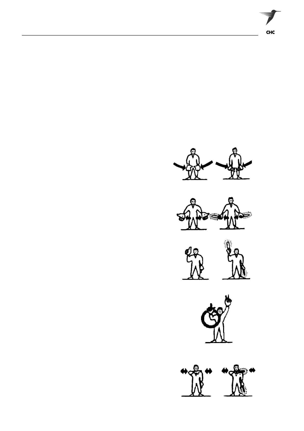
STANDARD HAND SIGNALS TO BE USED BY GROUND PERSONNEL MARSHALLING AIRCRAFT
Note 1
These signals are designed for use by the signalman, using lights when necessary, to
facilitate observation by the pilot, and facing the helicopter where the signalman can be
seen best by the pilot.
Note 2
The meaning of the relevant signals remains the same if bats, illuminated wands or
torch-lights are held.
Note 3
The aircraft engines are numbered, for the signalman facing the helicopter, from right to
left (i.e. No 1 engine being the left outer engine)
Note 4
Full marshalling signals can be found in CAO 20.3 Appendix 1
1
(a) Insert chocks
Arms down palms facing inwards,
swing arms from extended position
inwards.
(b) Chocks away
Arms down palms facing outwards,
swing arms outwards.
2
All clear
Right arm raised at elbow with
thumb erect.
3
Start engine
Left hand overhead with appropriate
number of fingers extended to
indicate the number of the engine
to be started, and circular motion
of right hand at head level.
6
Cut engines
Either arm and hand level with
shoulder, hand across throat, palm
downward. The hand is moved
sideways with the arm remaining bent.
ASNSW EC145 Cabin Staff Training Notes
Revision 1 - July 2010
page 5 of 6
Duties & Responsibilities
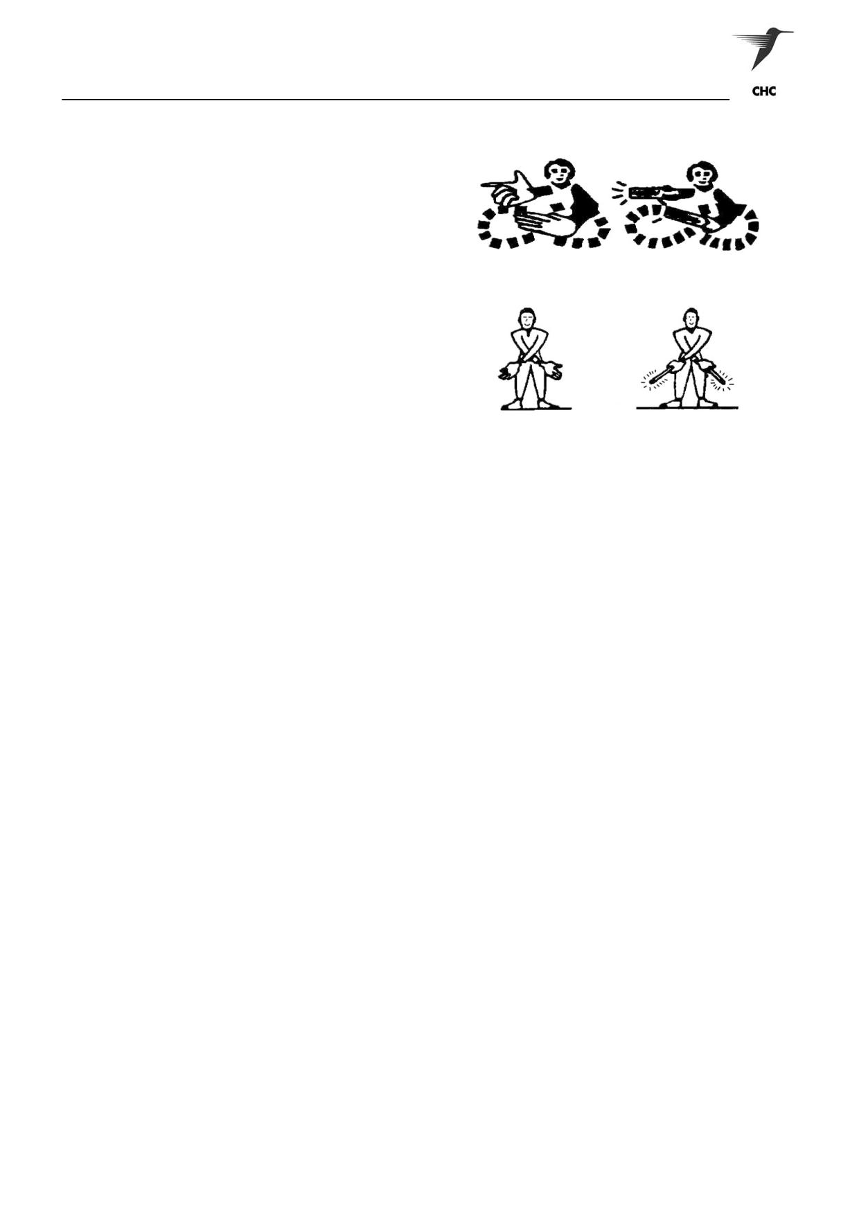
7
Engine Fire
One hand pointing to the corresponding
side of the aircraft on which the engine
fire has been identified. The other hand
describing a horizontal figure of eight.
8
Land
Arms crossed and extended
onwards in front of the body.
3
OPERATIONS MANUAL
The Operations Manual is issued to provide guidance, information and instructions to all Aircrew and
Operations staff in the performance of their duties. The Chief Pilot is responsible for the administration of
this manual and issue of amendments. Proposed amendments shall be submitted to the Chief Pilot in
writing, together with the justification.
Individual copyholders are responsible for the insertion of amendments upon receipt, signing the receipt
and returning it to the Chief Pilot’s office. Each base shall have a nominated “librarian” to ensure that
library and aircraft copies are correctly amended, to sign and return the issue receipt to the Chief Pilot’s
Office.
Amendments and instructions of an urgent nature will be notified immediately to aircrew by means of Flying
Staff Instructions (FSI). Each new FSI will be displayed in an Operations room for 1 month from the date of
issue, in addition to being placed in Section 5 of the Operations manual on issue.
FSI will remain in force until they are either no longer valid or have been incorporated in the Operations
Manual.
Staff Responsibility
It is the responsibility of Aircrew and Operations Staff to remain familiar with the contents of the Operations
Manual, Civil Aviation Regulations and Orders. Nothing in this Manual shall absolve all staff from their
personal responsibility of having up to date knowledge of all statutory regulations affecting their duties.
ASNSW EC145 Cabin Staff Training Notes
Revision 1 - July 2010
page 6 of 6
Airmanship
AIRMANSHIP
1
Definition
2
Teamwork
3
Crew Communication
4
Situational Awareness
ASNSW EC145 Cabin Staff Training Notes
Revision 1 - July 2010
page 1 of 3
Airmanship
1
DEFINITION
AIRMANSHIP IS DEFINED AS THE: “SAFE AND EFFICIENT OPERATION OF AN AIRCRAFT BOTH IN
THE AIR AND ON THE GROUND WITH SPECIFIC RELEVANCE TO CREW CO-ORDINATION, CO-
OPERATION, COMMUNICATION AND COMMONSENSE.”
2
TEAMWORK
Teamwork goes beyond providing a supportive environment where the crewmembers help each other,
without anyone feeling he is being criticised or made to look inadequate. Teamwork is where people take
initiatives, not just when there is crisis but when they can see the need to contribute to get the job done
better.
A key characteristic of a team is that the members have a common purpose and depend upon each other
for the successful attainment of the objectives. Aircrew are perfect examples of a team and many of the
research studies applied to non-aircrew teams have important implications for cockpit crews.
A lot of research has been done over the years, assessing why some groups work well and others work
badly. Professor Likert, at the University of Michigan, did considerable work on the subject and
concluded that “The superior of each work group exerts a major influence in establishing the atmosphere
of the work group by his leadership principles and practices. In a highly effective work group,
consequently, the leader adheres to those principles of leadership which create a supportive atmosphere
in the group and a cooperative rather than competitive relationship among members”. For example, the
manager shares information fully with the group and creates an atmosphere where members are
stimulated to behave similarly. Likert went on to suggest that when work team members had confidence
in the leader and felt they were consulted and involved decisions, then, provided the necessary
information was gathered, effective teamwork would emerge.
Some key characteristics of High Performing Teams that are applicable to Aircrew Team Management
are:
•
High performing teams gain a high degree of job satisfaction from their work
•
Team members cooperate well with one other
•
The team leader is well respected for the example he sets
•
High performing teams learn quickly from their mistakes
•
High performing teams have high problem solving skills and regularly review their performance
3
CREW COMMUNICATION
A process by which information, thoughts and feelings are exchanged in a readily and clearly understood
manner “I know you thought you understood what I said, but what bothers me is that what you heard is not
what I meant”.
Many research studies have highlighted the significant amount of time we spend in communication -
probably more than any other activity our waking hours. Yet few of us are good communicators or good
listeners. Even at the purely information level, it is claimed that 75% of oral communication is ignored,
misunderstood or quickly forgotten. The most important facets of our lives, however, depend upon ability to
communicate well - the cohesiveness of family relationships, the quality of our friendships and the
effectiveness in our jobs.
Many of us are guilty of jumping to conclusions, imposing solutions on people before they have really
understood the problems. Sometimes, we transmit information that to us seems concise, clear and
unambiguous but is interpreted by others as meaning something else completely. Although we can’t make
people respond in definite ways, we can often influence the way problem solving takes place by controlling
what we say and how we respond. This is what is meant by conversational control.
A clear understanding of the task at hand by all crewmembers is paramount in respect to its safe
completion. This understanding is achieved through good crew communications.
ASNSW EC145 Cabin Staff Training Notes
Revision 1 - July 2010
page 2 of 3
Airmanship
4
SITUATIONAL AWARENESS
An accurate perception of the factors and conditions that affect the aircraft and flight crew during a specific
period of time.
Achieving Situational Awareness
• Training
• Planning and preparation
• Visualise outcome
• Feedback
High situational awareness decreases risk.
Cockpit management skills contribute to situational awareness.
Clues to Loss of Situational Awareness
Operational
1
Failure to meet targets
2
Undocumented
3
Departing from SOP
4
Violating minimums of limitations
5
No one flying
6
No one looking out of the window
Human
7
Communications
8
Ambiguity
9
Unresolved discrepancies
10
Preoccupation of distraction
11
Confusion of empty feeling
ASNSW EC145 Cabin Staff Training Notes
Revision 1 - July 2010
page 3 of 3
Role Equipment
ROLE EQUIPMENT
1
Introduction
2
Life Jackets
3
Life Rafts
4
Rescue Harness
5
Capewell Winch Release
6
Wander Lead
7
Down The Wire Radio
8
Rescue Hoist
9
Stretchers
10
Tag Line
11
Rescue Strop / Hypothermia Strop
12
Hi-Line
13
Quick Splice Plate
14
Hand Held Search Light
15
Pyrotechnics and Marine Markers
16
Equipment Strap
17
Multi Purpose Winch Bag
18
Weighted Message Bag
19
Weighted Winch Bag
20
Survival Pack
ASNSW EC145 Cabin Staff Training Notes
Revision 1 - July 2010
page 1 of 25

Role Equipment
1
INTRODUCTION
All Role Equipment is supplied with operating/care instructions. It is the responsibility of all operators to
make themselves aware of these instructions prior to using the equipment.
2
LIFE JACKETS
The following Life Jackets are approved for use in company aircraft
Switlik HV 35C
Switlik CWV-35C
Switlik HV-35C
Introduction
The Switlik Life Jacket is the Company standard Crew Life Jacket.
Description
The Switlik Life Jacket is a blue vest style life jacket with a combination zipper and buckle fastening system
in the front with adjusting straps fitted to the back.
The jacket contains two horseshoe shaped, yellow autonomous chambers which, when donned sit behind
the head and in front of the chest area. The two chambers sit one on top of the other.
Each chamber is fitted with a CO2 cylinder and oral inflation tube. The front chamber is also fitted with a
whistle (left-hand side) and salt water activated light (right-hand side)
The jacket has two pockets located on the left and right hand side of the vest for stowage of survival
equipment. The content within the company standard Switlik HV-35C pockets is listed in the table below.
Left-hand Pocket
Right-hand Pocket
GEM MT410 406 Mhz PLB
Hand Held Mini Flares Mk8
Signalling Mirror
Pains-Wessex No. 1 MK4 Day/Night flare
ASNSW EC145 Cabin Staff Training Notes
Revision 1 - July 2010
page 2 of 25

Role Equipment
Operation
To inflate the jacket pull one or both inflation toggles located at the front of the jacket.
If auto inflation fails release oral inflation tube, separate valise Velcro manually and exhale into oral inflation
tube. Blow directly into tube. The tube is fitted with a one-way valve.
WARNING:
NEVER INFLATE JACKET INSIDE AIRCRAFT
To deflate life jacket depress on one-way valve.
SURVIVAL AIDS
GME MT410 EPIRB
Description
The GME MT410 is a self-contained Personal Locating Beacon (PLB), and is the company standard PLB.
The MT410 has a continuous transmission time of 24 hours minimum. Activation is achieved by breaking
the security seal and raising the antenna to the vertical locking position. Only when the antenna has
engaged and locked into the vertical will the unit be active. If the seal is broken the PLB should be
replaced, as the useable life of the PLB cannot be ascertained. There is a test function on the rear of the
unit; by inserting the yellow key (attached to the lanyard) into the testing slot, then slide the key downwards
will produce a flashing white light and an audible beep indicating the PLB is functional. If the PLB passes
this test but the security seal is broken the PLB is to be replaced.
Operation
Fully erecting the antenna to the vertical locking position will activate the PLB. By doing so, the security
seal will be broken. To deactivate the unit, insert the yellow key into the antenna latch, allow the release of
the antenna to fold-back and simultaneously deactivating the unit
ASNSW EC145 Cabin Staff Training Notes
Revision 1 - July 2010
page 3 of 25

Role Equipment
Signalling Mirror
The Signalling Mirror is simply a mirror, which uses the
principles of reflecting sunlight in a given direction. This survival
aid is very effective and can be seen by rescue craft from
considerable distances, in excess of 10 NM. Therefore, it
should be used in a random pattern reflecting light toward the
horizon.
Flares and Markers
The description, use and safety precautions for using the MINIFLARES, Day/Night Flares and Dye markers
is contained in part 2 sect 3 par. 16, Pyrotechnics and Marine Markers.
Switlik CWV-35C
Introduction
The Switlik Life Jacket is the Company standard Passenger Life Jacket.
Description
The Switlik Life Jacket is a blue vest style life jacket with a combination zipper and buckle fastening system
in the front with adjusting straps fitted to the back.
The jacket contains two horseshoe shaped, yellow autonomous chambers which, when donned sit behind
the head and in front of the chest area. The two chambers sit one on top of the other.
Each chamber is fitted with a CO2 cylinder and oral inflation tube. The front chamber is also fitted with a
whistle (left-hand side) and salt water activated light (right-hand side)
Operation
To inflate the jacket pull one or both inflation toggles located at the front of the jacket.
If auto inflation fails release oral inflation tube, separate valise Velcro manually and exhale into oral inflation
tube. Blow directly into tube. The tube is fitted with a one-way valve.
WARNING:
NEVER INFLATE JACKET INSIDE AIRCRAFT
To deflate life jacket depress on one-way valve.
ASNSW EC145 Cabin Staff Training Notes
Revision 1 - July 2010
page 4 of 25
Role Equipment
3
LIFE RAFTS
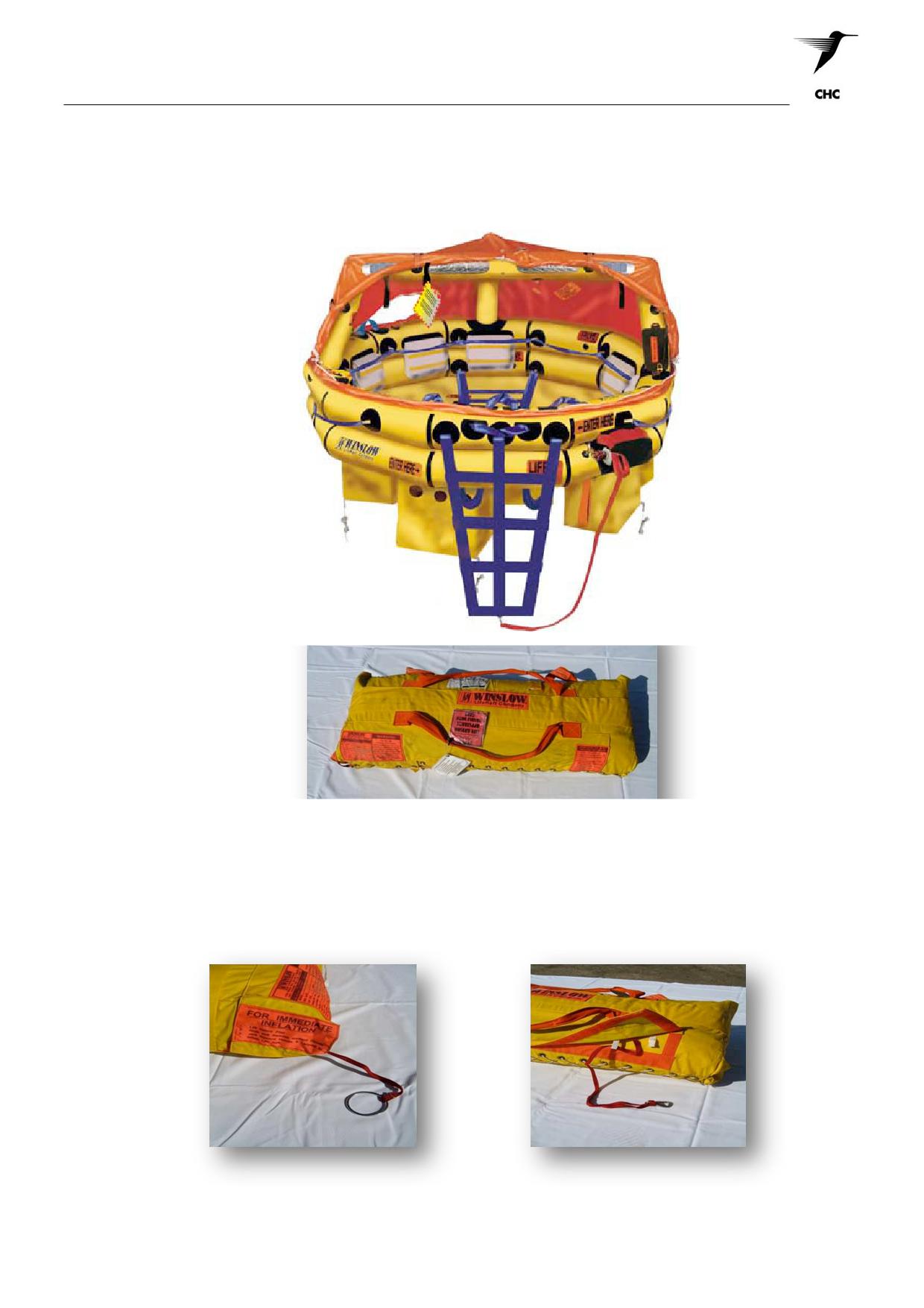
The life raft used at EMS bases is the Winslow model 710FA-AV(UL). They are intended for crewmember
and passenger use aboard aircraft during over water emergencies.
The rafts contain a survival kit, which depending on the rated capacity the amount of content will vary. The
following list is typical of a survival kit
• EPIRB
• Signal Mirror
• Hand held Aerial Meteor Flares
• Sea Rescue Ribbon
• Hand held Distress Flares
• Food Ration Bars
• Flashlight (2) w/spare Batteries & Bulb
• Anti-Sea Sickness Pills
• Sea Anchor
• Water-maker
• Heaving Line w/handle
• Whistle
• Pump w/Adapter
• Oral Inflation Tube
• Raft Knife
• Retaining Line
• Repair Tape
• Survival Manual
• Repair Clamps
• Thermal Protective Blankets
• PRV Plugs w/Tether
• Energy Bars
• Bailer Bucket
• Sponges
Operation
In anticipation of a ditching, rafts should be removed from their stowage and positioned by selected exits to
provide instant deployment - thus saving valuable time.
The red flap, marked with inflation instructions should face inboard toward the operator. The red flap
should then be unsnapped and opened, exposing the parachute pull ring handle and the retaining line pull
loop. The retaining line can be withdrawn sufficiently to secure the raft to the aircraft to prevent it from
drifting away when placed in the water. The life raft should be placed in the water clear of the aircraft
allowing as much area as possible to inflate without impeding passenger and/or crew egress from the
aircraft.
There are two methods of inflation. A short pull on the parachute pull ring will inflate the raft immediately.
The webbing type retaining line can be used to inflate the raft by grasping the hook end and after taking up
the slack in the line (5 metres), pulling with a sharp jerk.Inflation of the raft causes it to open the snaps of
its valise and deploy for boarding.
Winslow Life Raft
Description
The Winslow life raft is rated for 7 persons with a 10 person overload capacity. The life rafts are comprised
of two identical buoyancy tubes mounted one above the other, which are inflated from a single carbon
dioxide and nitrogen cylinder. Each buoyancy tube is fitted with a pressure relief valve to prevent over
pressurization during inflation and temperature fluctuations. Each tube is capable of supporting the
overload capacity of the raft. An automatically inflated triple arch supports a self-erecting canopy. The life
rafts feature an inflatable floor that when inflated, provides insulation in cold conditions or, when deflated,
maintains the life raft cool, ideal for tropical conditions. The inflatable floor allows for drainage of water to
allow for easier bailing. All inflatable parts of the life raft are fitted with manual inflation tubes.
The canopy can be opened into two different positions, sail or convertible. The canopy can also be
completely closed to keep water outside the life raft.
A pentagonal ballast system is installed under the floor for added stability in boarding the life raft and in
high sea states. A righting line is provided in case the life raft inflates in an inverted position. Instructions
for righting are printed on the lower tube. Two boarding ladders, one at either end of the life raft, are
provided for ease of entering the life raft from the water. In addition, an inside-the-life-raft assist-boarding
ladder is provided to provide additional assistance in boarding the life raft.
ASNSW EC145 Cabin Staff Training Notes
Revision 1 - July 2010
page 5 of 25
Role Equipment
Attached to the life raft is a floating knife, self-deploying sea anchor, heaving line and internal and external
water activated lights. The knife, which is located at the main entrance and attached to the upper
buoyancy tube, is provided to cut the mooring line from the aircraft in an emergency. The sea anchor is
provided to reduce drift and aid in stabilization in high sea states. A survival pack is located inside the life
raft.
Operation
The life raft can be inflated via the retaining line after all line as been withdrawn and a sharp jerk is given,
or for quick release using the inflation ripcord handle. All other procedures are listed under the EAM T
series operation.
Immediate Inflation Ring
Inflation Lanyard
ASNSW EC145 Cabin Staff Training Notes
Revision 1 - July 2010
page 6 of 25

Role Equipment
4
HARNESS
Introduction
SARQUIP International manufactures the rescue harness approved for use. The harness is designed for
aviation use in helicopter aircrew, rescue crew, camera and rappelling operations. When used in an
aircraft the rescue harness must be used in conjunction with a cabin wander lead that must be secured to
primary and secondary hard points by means of an interconnecting restraint. When used externally from
the aircraft the harness must be used in conjunction with an aviation approved winch release assembly
(Capewell).
Use
To fit the harness place shoulder straps over the shoulders. Pass one leg strap around each leg and
attach the V-Ring to the snap hook, pass the loose end through the elastic keeps provided. Adjust the leg
and shoulder straps for a comfortable fit.
Connect the waist and chest straps and adjust for firm fit. Secure all loose ends to Velcro pads provided.
Additional Equipment
Additional attachments to accompany the harness include a strobe light secured to the left hand shoulder
strap by a Velcro retainer, and a J-Knife to be secured to the waist strap.
ASNSW EC145 Cabin Staff Training Notes
Revision 1 - July 2010
page 7 of 25

Role Equipment
Care
Under normal usage the harness has a ten-year total life from date of manufacture. If there is no label or
the date of manufacture is illegible the harness is to be considered unserviceable. The harness should be
returned to the manufacture each 12 months for inspection and re-certification. If the webbing, stitching or
fittings become damaged it should be repaired or replaced. The harness is to be examined for chaffing,
cuts, damaged fittings and worn stitching prior to using.
If the harness is exposed to a free fall of 0.6m it is to be returned to the manufacture for inspection and if it
is exposed to a free fall of 2.0m it must be retired from service.
The harness can be cleaned with cool water and a mild detergent followed by a rinse. Always rinse the
harness in fresh water after use in salt water
5
CAPEWELL WINCH RELEASE
Introduction
The Winch Release or Capewell comprises of two components and are not interchangeable with any other
assembly. The Winch release has been designed for aviation use with helicopter rescue crew and
rappelling operations and must not be used for any other purpose.
Use
The Quick Release is to be secured to both harness take up point D-rings with the snap hooks facing down
and towards the body. The Winch Release should be set up so as the release handle is located on the
users primary side i.e. if you are right handed then the release handle is on your right side. Connection to
the winch hook is via a steel Karabiner (provided). The gate of the Karabiner is to face the body of the
operator.
The Quick Release requires two separate movements to initiate release; both can be completed with one
hand. Lift the spring loaded release handle safety cover, which will then expose the cable type release
handle. Pull the cable type release handle and the system will release
NOTE:
The system will only release under load
CAUTION:
When activating the Quick Release under load, it is advisable to use your free hand to
shield your face from any possible dynamic action from the release mechanism.
Care
As for Harness
ASNSW EC145 Cabin Staff Training Notes
Revision 1 - July 2010
page 8 of 25

Role Equipment
6
WANDER LEAD
Introduction
SARQUIP International manufactures the Wander Lead and Wander Lead Release assembly. Although
the Wander Lead and Wander Lead Release are two separate parts, each having separate identification
labels and serial numbers, for the purpose of these training notes, term “Wander Lead” means the
complete unit. The Wander Lead has been designed as a restraint for aviation use.
Use
The Wander Lead must only be secured to an aviation approved primary load bearing attachment point
(hard point) then subsequently to a secondary hard point within the aircraft cabin by means of aviation
approved Single Point Restraint.
The slim load bearing snap hook must be secured to the primary attachment point with safety pin in place,
and positioned so that there are no twists in the lead and with the Wander Lead release handle facing
outboard of the wearer.
The winged load bearing snap hook must be secured to one harness take up point D-ring. Depending on
which side of the aircraft you are working from will depend on which side of the harness you connect
to.however, always ensure your Wander Lead is connected to the inboard side of your harness when in
your working position.
CAUTION:
The winged load snap hook must connect to the harness D-Ring from the lower side (i.e.
the winged gate to face upwards when connected). You must also ensure that the winged
snap properly closes once connected to the harness.
The three-ring release incorporated within the Wander Lead is a double action system and will disconnect
under minimal load. To activate the release, peel over the red padded handle and then pull outward firmly.
There is a small ring fitted below the slimsnap hook for securing the wingedsnap hook when the Wander
Lead is not in use.
A Velcro tunnel and two elastic keepers are provided for securing communication leads.
An adjuster as been incorporated within the Wander Lead to ensure the correct length is available for each
situation. The Wander Lead must be checked for correct length every time the lead is used to prevent
movement outside the aircraft cabin.
An elastic keeper must be positioned directly behind the adjuster to reduce free play through the adjuster.
To adjust the length of the Wander Lead lift the yellow tab on the slide adjuster and pull the webbing
through the adjuster to the desired length. Excess webbing can be secured with elastic keepers provided.
CAUTION:
Failure to check length adjustment could result in injury from a free fall.
ASNSW EC145 Cabin Staff Training Notes
Revision 1 - July 2010
page 9 of 25
Role Equipment
Three-Ring Release Inspections
• The Three Ring Release should be inspected prior to every use
• Cleaning and disassembly should be carried out once a month, more often in humid, dirty or cold
conditions
• To test the Three-Ring Release, place the Wander lead under load and pull the red release handle
• The rings should operate under a load of 20lbs or less
• The red locking loop that holds down the small ring must be flexible and checked for wear
• Flex the webbing near where it passes through each ring to remove any deformation in the webbing
• Check the Velcro on the release handle and webbing, it must be clean and holding well
• All rings must have metal-to-metal contact, and should be rotated regularly
• Check the terminal fitting at the end of the housing for security and the housing for dents or damage. If
the housing is damaged it must be replaced
• Run the cable back and forth through the housing
• Lightly lubricate the cable with a silicone-based lubricant
• Do not let the release assembly become wet in cold weather. It may freeze and stiffen the webbing,
resulting in a failure to release
Assembly of the Three-Ring Release
• With the snap hook facing down, position the Wander Lead with it’s rings uppermost
• Pass the middle ring under the base ring and flip it through
• Pass the small ring under the middle ring and flip it through
• Pass the red loop over the small ring only, then pass it through the grommet in the Wander Lead until it
forms a loop at the back of the lead
• Place the yellow cable through the red loop and down into the webbing stowage pocket at the back of
the lead
• Place the red release handle back into the slot within the Wander Lead then back onto the Velcro pad
• Inspected the lead for correct fitment
Care As for harness
7
Down The Wire Radio
Introduction
The ICOM IC-M72 Transceiver (ICOM) is a waterproof handheld marine band
VHF radio with a frequency range covering all marine channels. The unit is
waterproof to a depth of 1 metre for 30 minutes using either the stand-alone
radio or in conjunction with the speaker/microphone attachment. For use during
winch operations over land the ICOM is fitted with a helmet adapter, which allows
two-way communications between the RCM and aircraft. The ICOM is the RCMs
primary means of communications for all down the wire operations. It is a useful
tool when there is a requirement to communicate with the winch operator for
safety reasons during a winch.
CAUTION:
Communications with the winch operator during the actual
process of winching should only be conducted when pre briefed
or where personnel or aircraft safety is a factor. All
communications should be kept to an absolute minimum.
The radio is fitted with a number of functions. The following is a list of key
functions the user needs to operate the radio;
a.
Volume/on/off control
Situated on top of the radio and is turned clockwise to turn on and
increase the volume
b.
Squelch
Sets the squelch threshold
ASNSW EC145 Cabin Staff Training Notes
Revision 1 - July 2010
page 10 of 25
Role Equipment
c.
PTT switch
Transmits when pushed and receives when released
d.
Function display
Displays radio functions, such as battery level, selected channel, transmit indictor
e.
Channel up/down
Selects desired channel
f.
Internal microphone
Used to transmit when using the radio without attachments
g.
Internal speaker
Used to receive when using the radio without attachments
h.
Battery pack release button
Used to connect/disconnect the battery pack
i.
Lock button
Press and hold to lock the desired channel
Use of the ICOM
As stated the ICOM is to be used for all down the wire operations both land and water and is to be fitted
inside the left hand pocket of the Switlik life jacket when worn. For over land operations the helmet adapter
is used with all excess cable being stowed within the life jacket pocket.
For over water operations the ICOM is again positioned in the life jacket pocket with the speaker
microphone fitted in such a way that the RCM is able to communicate with the aircraft. It is recommended
that the microphone be positioned up near the wearer’s head on either the life jacket outer valise or rescue
harness shoulder strap.
The speaker/microphone must be attached prior to the radio being immersed in water. When attaching the
speaker/microphone ensure that the connection is fully inserted and secure to avoid water immersion into
the radio
Note: Keep the jack cover attached when the speaker/microphone is not in use to prevent corrosion to
the pins.
Speaker Phone
Helmet Jack
The radio also has a helmet attachment lead, which allows the user to plug their helmet into the radio and
operate the radio via the PTT switch. Both the speaker/microphone and helmet attachment lead are fitted
to the radio via the connector situated on top of the radio next to the antenna
Note: The helmet attachment is NOT waterproof.
Note: There is no side tone when using the helmet attachment lead.
The radio has a battery indicator, charging will be required if showing less than 2 bars
ASNSW EC145 Cabin Staff Training Notes
Revision 1 - July 2010
page 11 of 25
Role Equipment
8
RESCUE HOIST
Introduction
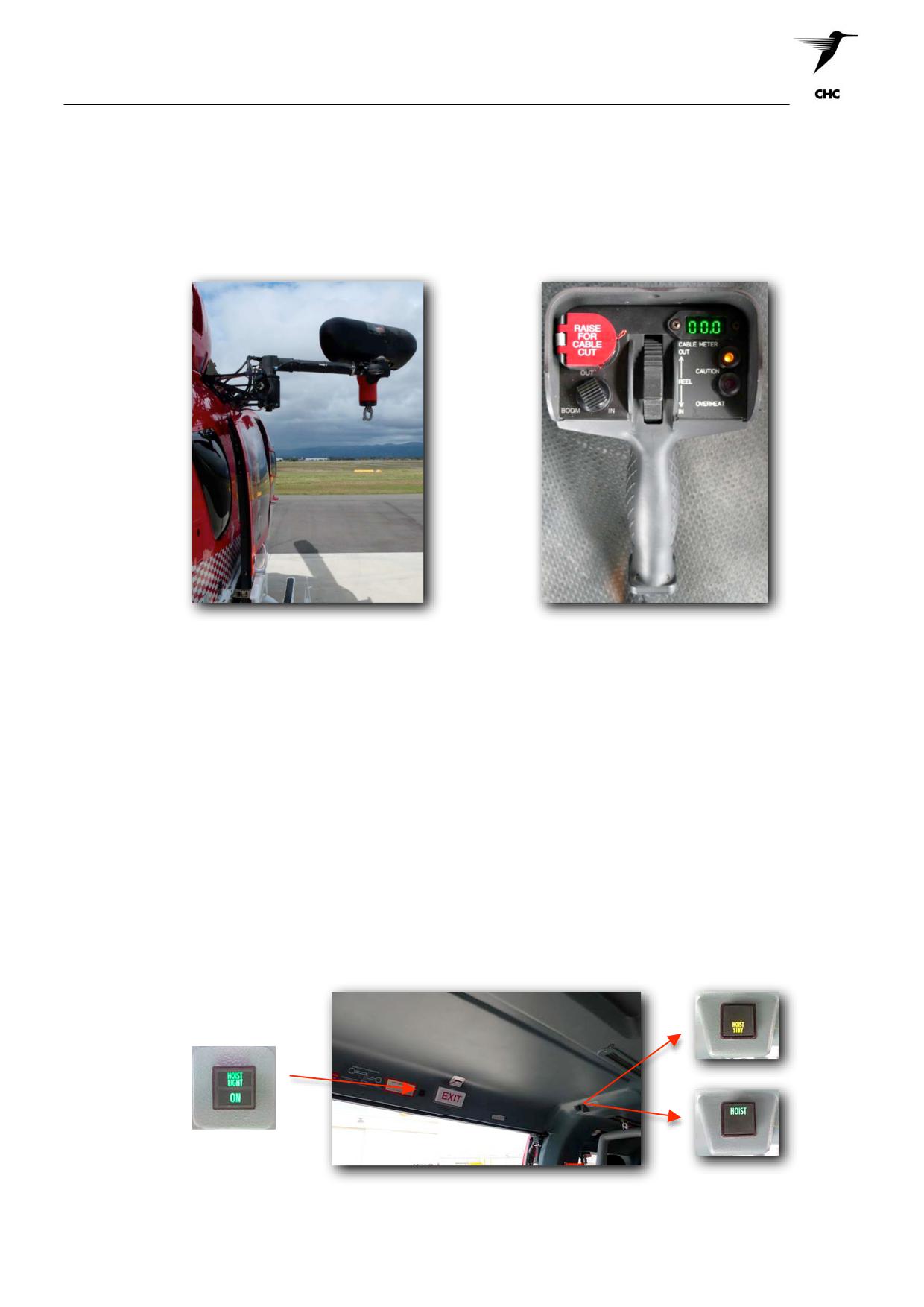
The Goodrich Hoist is a variable speed electric hoist mounted externally to the right hand side of the
aircraft on a motorised swing-arm. The hoist can be operated either by the cockpit’s cyclic control; or the
cabin’s control pendant operated by the Aircrewman.
Goodrich Hoist attached to EC145
Hoist Pendant
Description
The Goodrich Hoist has is fitted with 295 feet (90m) of useable cable. It has a maximum operating load of
600 lbs (272 kg).
The hoist has variable operating speeds to 250fpm utilising the winch control pendant and/or the pilot’s
cyclic control. Limit switches mounted on the hoist control operations at 100fpm between 1 - 10 feet reel-
out, where winching in is reduced to 50fpm. The final ‘foot’ is further reduced to 15fpm. Limit switches stop
the hoist when the cable is fully extended or retracted.
The hoist system includes a remotely operated cartridge actuated cable cutter. The cable cut switches are
wired in parallel and are located on the pilot’s collective and cabin hoist pendant. The cable cut circuit
breaker must be IN for the cable cut to be activated. The hoist is fitted with searchlight mounted in the hoist
boom.
The hoist power and hoist light switches are mounted on both sides of the forward cabin ceiling. The hoist
light switch is directly mounted above the cabin doors, where the hoist power switches are mounted rear of
the cabin ceiling doorway.
Hoist Light Switch
Hoist Power Switches
CAUTION:
All hoist switches are to be controlled by the winch operator only.
ASNSW EC145 Cabin Staff Training Notes
Revision 1 - July 2010
page 12 of 25
Role Equipment
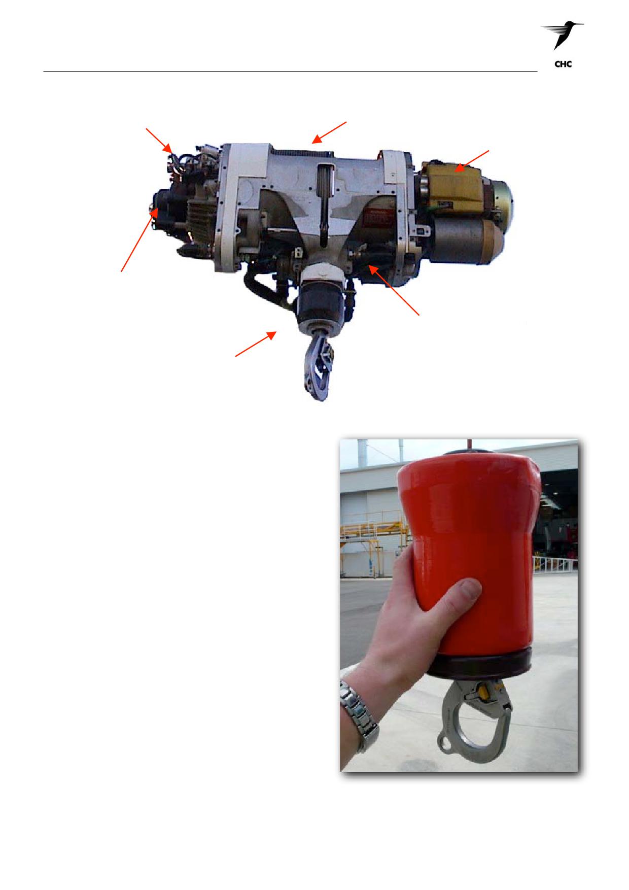
Level Wind and
Limit Switch
Storage Drum Assembly
Installation
Main Drive
Motor
Automatic Brake
Assembly
Cable Cutter
Hook
Assembly
Control Pendant
The hoist can be operated up or down at
continuously variable speeds from rest to maximum
speeds.
Cockpit Control
The hoist is operated up or down at a fixed speed
of 100fpm. Cockpit control signals have overriding
authority over control pendants signals.
Winch Hook
The hoist is fitted with a swivel hook, connected to
the cable via a swagged ball and collets inside a
rubber buffet. The hook is fitted with a spring
loaded gate that must be opened by depressing the
two yellow lugs situated either side of the gate to
place or remove equipment from the hook.
The hook is also fitted with a hard-eye on the back
of the hook for placement of the Hi-line snap-hook.
CAUTION:
Ensure equipment is not caught on the hard-eye prior to being lifted with the hoist, and that
all equipment sits freely in the bight of the hook. Always be mindful of D -Ring Reversal /
Dynamic Rollout
ASNSW EC145 Cabin Staff Training Notes
Revision 1 - July 2010
page 13 of 25

Role Equipment
9
STRETCHERS
MEDEVAC II Titanium Rescue Stretcher
Introduction
The MEDEVAC II is an approved optional emergency stretcher used by the Company.
The strength of the titanium frame and overall robust design affords the patient ample protection during
rescue operations. The capability to fold the MEDEVAC stretcher in half allows for easier stowage.
Description
The MEDEVAC stretcher is constructed of aerospace ATM Grade 9 titanium alloy tubing and components.
A smooth, corrosion-resistant plastic netting (with 12mm openings) is used to support and provide comfort
for the patient. Hand holds are situated on both sides for carriage over land.
The dimensions when assembled are:
Length
198cm 78 inches
Width
61cm
24 inches
Depth
50.5cm 10 inches
Weight
10kg
22 lbs
Load Capacity
272kg
600 lbs
Use of the MEDEVAC Titanium Stretcher
Preparation of patient
1. Deploy the stretcher to a suitable location near the
patient ensuring that the two halves are secured tightly
and correctly with no loose articles.
2. Once at the scene, assemble the stretcher ensuring that
the threaded couplers (2) are fully done up and secure.
Lay all patient restraints and lifting slings outside the
stretcher frame in readiness to accept the patient.
WARNING: ENSURE THAT THE THREADED COUPLERS ARE SECURELY IN PLACE PRIOR TO
USE - DO NOT OVER TIGHTEN.
3. Place the patient into the stretcher ensuring that they are orientated correctly and positioned so
that the stretcher when lifted, will hang in a slightly feet down position.
CAUTION:
Where practicable, the patient is to be briefed accordingly and provided with ear and eye
protection.
4. Place the two shoulder straps over the patient and secure them to the corresponding mate (colour
coded) located at the centre of the stretcher then tighten as necessary.
5. Place all four (4) patient restraints across the patient and secure them to the corresponding mate
(colour coded) on the opposing side of the stretcher and tighten as necessary.
CAUTION:
Loose straps can flutter, creating a potential hazard to both the patient and RCM. All
excess straps must be secured by means of the elastic loop provided.
NOTE:
To assist in preventing the patient from sliding downward toward the foot end it is
acceptable to have the chest restraint strap routed under the patient’s upper arms between
the arms and chest (arm pit) on both sides and then secured accordingly.
NOTE:
The patient’s arms are to be secured beneath the waist strap.
ASNSW EC145 Cabin Staff Training Notes
Revision 1 - July 2010
page 14 of 25

Role Equipment
6. With the patient properly secured, the head and foot end lifting slings are brought to the centre
point of the stretcher and secured by means of the “Snap Hook” and small “D” Ring.
NOTE:
Ensure that there are no twists in the lifting slings prior to the lift.
10
TAG LINE
Stuff Bag Type
The Stuff Bag Type Tag Line presents in a nylon bag containing the following components;
•
130 metres of 6mm high visibility reflective
cordage (not tied in) incorporating an
optional weak link assembly,
• Instruction guide,
• Third party ear & eye protection,
• Safety gloves, and
• Hook knife,
When preparing the tag line for use the connecting
snap hook is fed from the choked bag opening and
connected to the stretcher via a Ronstan Quick
Release. The quick release can be activated by the
RCM attending the stretcher or by the winch
operator at the aircraft door when necessary.
CAUTION: The RCM is to carry a Hook Knife as
a backup to the release system.
A weak link assembly is supplied as an option for those occasions where the surrounding
terrain/obstructions pose a potential snagging hazard. When required the weak link is utilised by
simply connecting the tag line to the stretcher quick release via the weak link snap hook.
Note: Notification to the aircraft crew of non-use of the weak link is mandatory.
The tag line bag can be managed in one of two ways; on the ground at the RCM’s feet or under
the TLA’s arm with the carry handle over the shoulder.
Tag line control when being payed out is achieved by the RCM applying appropriate friction with
the gloved hands. A slack tag line can be controlled by either; carefully retrieving the excess line
hand over hand back onto the surface immediately in front of the RCM, or by the RCM walking
backwards away from the target.
WARNING: AT NO TIME IS A LOOP OF LINE ALLOWED TO BE WRAPPED AROUND THE
TLA’S HAND IN ORDER TO GAIN MORE PURCHASE.
CAUTION: Use of heavy-duty leather gloves supplied is recommended as friction burns may
occur.
CAUTION: To safely achieve a foul free payout of line it is essential that the tag line has been
correctly flaked into the bag.
WARNING: THE TAG LINE STUFF BAG IS NOT TO BE SECURED TO THE TLA IN ANY
WAY
ASNSW EC145 Cabin Staff Training Notes
Revision 1 - July 2010
page 15 of 25

Role Equipment
11
RESCUE STROP / HYPOTHERMIA STROP COMBINATION
Introduction
The Rescue Strop/Hypothermia Strop combination is used as a Rescue Strop for recovery of experienced
or pre-briefed personnel who are in a fit state to keep them in the strop. They can be specifically briefed
beforehand, or by a Rescue Crewman lowered to brief them prior to the winch.
When used for water rescues the Hypothermia strop is separated from the Rescue Strop valise and is used
for recovery of personnel who are suspected of suffering from hypothermia. The device is designed to
maintain the survivor in a sitting position(with the red hypothermic strop positioned under the knees) across
the front of the RCM whilst being winched to the aircraft.
Description
The Rescue Strop/Hypothermia Strop Combination is a horse collar shaped device, which is connected to
the winch hook by means of a ‘D’ ring. A snap hook at the free end of the strop connects to small ‘D’ ring
below the winch attachment point which then gives the strop its horse collar shape.
CAUTION:
The strop also incorporates a chest strap and must be in fitted during land winch
operations
12
HI-LINE
A Hi-Line procedure is used when conducting either over water or over land rescue winch
recoveries when normal winching would be hazardous.
a When the winching area is confined or obstructed in such a way that there is a risk of the
winch cable snagging or the RCM/MA striking obstructions.
b The vessel or winch area is so small that the Pilot cannot remain in visual contact whilst in
the hover.
c When normal winching techniques would be unable to effect transfer.
During night Hi-line transfers, the shot bag shall be illuminated with high intensity artificial
light sticks (Cyalume).
d When conducting Hi-line transfers to/from a life raft it is acceptable that once the RCM has
entered the raft that the hi-line shot bag and all excess rope be lowered down in between
the raft chamber and the outer boarding rope. This will ensure that all excess rope will be
out of harms way during the transfer process.
NOTE:
It may be advisable to attach an additional shot bag for this procedure to assist in
the sink rate of the excess line.
ASNSW EC145 Cabin Staff Training Notes
Revision 1 - July 2010
page 16 of 25

Role Equipment
e.
When conducting a stretcher lift recovery from a vessel utilising the Hi Line procedure it
may be necessary to route the Hi Line through the Tag Line quick release Ronstan. his
particular configuration ensures the stretcher remains under the positive control of the
TLA and that the weak link functionality is maintained during the winch in process.
CAUTION: When configuring the Hi Line through the quick release Ronstan it is essential that
the Hi Line hand hold is on the outboard side.
When recovering the RCM last from the scene, the hi-line can either be recovered with him or
discarded, which ever is deemed as the safest option by the crew.
Description
The Hi-Line is the name given to describe the piece of equipment in its entirety. The various
components of the equipment are:
a.
Canvas or nylon pack cover.
b.
30 or 45 metres (100 or 150 ft) cord stowed inside the pack cover.
c.
The cord has a shot bag on one end (the "down" end) and a soft eye with snap hook on
the other and (aircraft end). The snap hook is attached to a 136 kg (300 lb) cord loop
which acts as a weak link. The cord loop is attached to the aircraft winch hook.
A Carabiner snap hook is attached to the outer casing of the pack; and is used to secure the Hi-
line to the aircraft floor.
Hi - Line Kit
ASNSW EC145 Cabin Staff Training Notes
Revision 1 - July 2010
page 17 of 25

Role Equipment
13
QUICK SPLICE PLATE
Introduction
The Emergency Quick Splice Plate (QSP) assembly is designed to be used in place of the normal rescue
hoist hook in the event that the normal hook has been cut away or damaged.
Description
The QSP assembly is manufactured from anodized aluminium alloy 75mm x 195mm x 12mm. It has a
90mm diameter bumper disc at one end and a rotating swivel at the other. Fitted to the swivel is a DMM
C840 Karabiner for the attachment of rescue equipment and personnel. The bumper disc has a spring clip
fitted which locks the cable in place once it has been routed through the numbered slots.
The QSP has five (5) 9mm wide slots cut into it, which are bevelled in the direction in which the winch
cable is to be routed. These slots are numbered 1 to 5 and have arrows marking the layering direction to
assist in the cable feeding sequence. The No. 5 slot has a spring clip which locks the cable within the slot
preventing it from slipping out.
WARNING:
THE EMERGENCY QUICK SPLICE PLATE AS DETAILED ABOVE IS DESIGNED FOR
USE WITH 3/16" RESCUE WINCH CABLE ONLY.
CAUTION:
Once used the QSP is to be inspected and certified ‘Serviceable’ by an appropriate person
prior to further use.
Quick Splice Plate - Free Bitter End
Fitment
The tail of the rescue winch cable is fed on to the QSP by first laying it along the “CABLE BITTER END”
slot leaving at least 3” (80mm) of overhang. It is then a process of routing the cable through the numbered
slots following the arrows and keeping in the correct numbered sequence. It is important to keep the cable
as tight as possible during this process avoiding any large loops.
When feeding the cable onto the No. 5 slot, ensure that the spring clip locks the cable within the slot. Once
securely locked into the No. 5 slot the cable is then locked into the central position of the bumper disc by
passing it through the spring lock on the bumper assembly.
The free end (Bitter end) of the cable is then fed through and locked into the No.5 slot by passing it over
the cable loop running between the No.5 and No.4 slots. It is then to be locked into the central position of
the bumper disc by passing it through the spring lock on the bumper assembly. This then assures positive
cable lock off regardless of loading.
With the rescue winch cable correctly fed through all of the numbered slots, and in the correct sequence as
detailed above, the QSP is now ready for use.
ASNSW EC145 Cabin Staff Training Notes
Revision 1 - July 2010
page 18 of 25

Role Equipment
Correctly Threaded Quick Splice Plate
CAUTION:
The QSP maximum allowable load is 600lbs (272kgs)
CAUTION:
Gloves must be worn when handling rescue winch cable.
WARNING:
IT MUST BE NOTED THAT THE RESCUE WINCH LIMIT RETARD SWITCHES MAY BE
INOPERATIVE FOLLOWING THE CUTTING OF THE CABLE AS THE OVERALL
LENGTH HAS BEEN ALTERED.
14
HAND HELD SEARCH LIGHT
The crewman for night searches uses the Hand Held Search Light over land/water and to assist in the
illumination of the tail area of the aircraft and surrounds during night confined area/winch operations
Description
The unit is a hand held search light with a 14 cm diameter lens with adjustable focus control. It is powered
by 14 volts DC and can be connected to an appropriate outlet within the aircraft cabin by means of a
flexible lead. A momentary trigger switch located at the top of the handgrip activates the light. A nylon
cord-retaining lanyard is secured to the top of the handgrip and is to be worn around the operator’s wrist for
security during use. Concealed within the handgrip is a spare bulb.
Hand Held Search Light
ASNSW EC145 Cabin Staff Training Notes
Revision 1 - July 2010
page 19 of 25

Role Equipment
Use
Once connected to the 14 VDC outlet, depressing the momentary trigger switch activates the light. The
light illuminates immediately.
CAUTION:
A clearance to illuminate the light must be given by the aircraft captain prior to activation.
CAUTION:
The operator is to ensure that the light is pointing outside the aircraft and that the retaining
lanyard is fitted to his wrist prior to use.
Once the light has been illuminated the crewman controls the beam by pointing the light in the desired
direction. The beam width can be adjusted from a pencil beam to a wide beam by rotating the outer lens
housing in the appropriate direction. The recommended search height when using the light is not greater
than 500 ft AGL.
CAUTION:
The lens cover may be hot after use and therefore care should be taken when handling the
light during stowage or if setting down on a soft surface.
CAUTION:
When using the light the operator is to ensure that the unit is not placed out into the airflow
above 40 kts IAS.
15
PYROTECHNICS
There are many and various types of pyrotechnics in use by both civil and military organizations. All are
designed to attract the attention of rescue agencies by means of being highly visible whether from a hand
held position, surface deployment or deployment at height.
All pyrotechnics have one thing in common and that is a chemical reaction of some kind is required to
activate the device. Because of this chemical reaction and the subsequent flame, flare or smoke extreme
care should be taken when using them.
Operators should read the instructions on the device carefully before activation and dispose of the device
correctly after use.
a.
Lifesmoke MK 3
The Mk3 Orange smoke produces a dense
bright orange smoke for three (3) minutes and
is suitable for daylight use only. They are
used to initially mark targets and as a drop
timing reference marker.
Method of Activation
1
Remove plastic lid
2
Tear off foil cover
3
Pull cord firmly
4
Plastic claws separate and release striker
5
Throw marker down and out of aircraft
CAUTION :
Ignition of the MK 3 orange smoke is virtually instantaneous following activation. Activation
of the ring-pull causes a stream of silicone to be discharged from the ring-pull hole.
ASNSW EC145 Cabin Staff Training Notes
Revision 1 - July 2010
page 20 of 25

Role Equipment
b.
Signal Distress Day/Night Mk4
These hand held devices have a day and night signalling capability depending on which end is activated.
The flare end, which is identified by a ribbed section on the device, has a bright red flare where as the
smoke end emits thick orange smoke. The red flare burns for 20 seconds at 10,000 candela and the
smoke burns for minimum of 18 seconds. Where possible gloves should be worn, as it does get hot.
When only one end of the distress signal is used, it should be doused in water to allow stowage for further
use of the remaining signal.
c.
Mini flare Mk8
The lightweight, Pains Wessex compact distress signals pack contains 3 red aerial flare cartridges and a
penjector firing mechanism, all enclosed in a tough, water-resistant case. The penjector is fitted with a
stainless-steel spring and striker pin. It features a slot for easy loading and unloading of the flare
cartridges. These are stored inside the casing on an elastic lanyard to avoid them being lost when the base
cap is unscrewed. Each cartridge projects its payload to a height of over 45 meters, burns for up to 5
seconds at a minimum of 10,000 candela and is visible for at least 5 miles in daylight increasing to 10 miles
at night, depending on weather conditions
ASNSW EC145 Cabin Staff Training Notes
Revision 1 - July 2010
page 21 of 25

Role Equipment
d.
Marker Location Marine - MK25 (white smoke marker)
The Marker Location Marine Mk25 (commonly referred to as the white smoke marker) is designed to mark
a position at sea, either by day or night and to provide a visual indication of the surface wind. At one end of
the white smoke case is a heavy aluminium base containing a salt water-activated battery, which is
protected from the water, by two base plugs fitted into holes on opposite sides of the base assembly. The
plugs are held in position by an arming plate on the base marked safe and armed. The rest of the cylinder
contains the pyrotechnic mixture, an electronic ignition device and a venting chimney.
The venting chimney remains sealed until a build-up of gas forces the sealing device out after ignition has
taken place.
The marker emits a 30 centimetre (cm) yellow flame and white smoke. It burns for approximately 15 plus
or minus 3 minutes.
Whilst the markers are designed to be used in salt water, it will function satisfactorily in solutions of
approximately half the normal salinity.
The Mk25 will not function in fresh water.
The pyrotechnic candle contains approximately 0.9 kilogram (kg) of red phosphorus, manganese dioxide
and magnesium powder mixture and a starter mix. The starter mix consists of 26.5 grams of lead peroxide,
powdered silicon and cupric oxide activated by an electrical squib, which imitated by the salt-water battery.
CAUTION:
The accumulated gas emitted from the MK25 is both toxic and flammable.
A scuttling pellet consisting of 43 grams of magnesium and barium nitrate is fitted below the pyrotechnic
candle.
WARNING:
IGNITION OF THE SCUTTLING PELLET IS OFTEN ACCOMPANIED BY A VIOLENT
DISRUPTION OF THE MARKER, WHICH MAY THROW MOLTEN ALUMINIUM,
ALUMINIUM FRAGMENTS AND BURNING PHOSPHORUS UP TO 10 METRES.
THEREFORE, HELICOPTERS ARE TO ENSURE THAT THE MARKER REMAINS AT
LEAST 10 METRES OUTSIDE THE ROTOR DISC.
For safety, armed Mk25's are not to be brought back and returned to the SAR store - they are to be
dispatched prior to return, whether actually required or not. Therefore, they are not to be armed until they
are needed.
WARNING:
KEEP THE MARKER AWAY FROM WATER ONCE THE PLUGS HAVE BEEN PUSHED
IN, AS IT ACTIVATES WITHIN 10 TO 20 SECONDS OF WATER ENTERING THE
CAVITY, EMITTING FLAME, TOXIC SMOKE AND GASES.
ASNSW EC145 Cabin Staff Training Notes
Revision 1 - July 2010
page 22 of 25

Role Equipment
16
EQUIPMENT STRAP
Introduction
The Equipment strap enables the RCM to carry equipment on the winch hook with him in such a manner
that it hangs low and controlled between his legs. This technique enables the RCM to use both hands while
fending off the aircraft extremities and other obstructions during the winching process.
Description
The equipment strap is an 80cm length of nylon webbing with a captive eye karabiner at each end. One
karabiner is used for attaching the strap to the winch hook and the other being for the securing of
equipment.
Use of the Equipment Strap
The equipment to be carried is connected to the equipment strap by one of the karabiners and then
checked for security. When ready the RCM connects the strap and himself to the winch hook. Once at the
scene and ready to winch the RCM exits the aircraft as per normal operations.
With the RCM balanced and stable at the aircraft door, the winch operator passes the equipment to be
carried out of the aircraft and down between the RCMs legs. A standard winch delivery is then completed
with the RCM taking particular care when guiding the equipment and himself down past the aircraft
extremities.
Retrieval to the aircraft is accomplished as per a standard rescue winch recovery with the equipment to be
carried connected securely to the strap and hanging between the RCMs legs. Once the RCM is at the
aircraft door and stable, the winch operator recovers the equipment into the aircraft from between the
RCMs legs. As the equipment is brought into the aircraft the RCM follows in behind it. The RCM then
secures the equipment and himself before getting a clearance to disconnect from the winch hook.
Equipment Strap
ASNSW EC145 Cabin Staff Training Notes
Revision 1 - July 2010
page 23 of 25

Role Equipment
17
MULTI PURPOSE WINCH BAG
The Multi Purpose winch bag is designed to winch items or equipment to or from the scene if they are not
rated or approved to connect directly to the winch hook. The bag is constructed from Herculite (heavy-duty
weatherproof material) with a Velcro opening flap. The rated webbing stitched around the bag create two
loop ends, which connect to the winch hook.
18
WEIGHTED MESSAGE BAG
The weighted message bag allows the Aircrewman to establish written communications with crews or
survivors at scene. The Herculite constructed bag allows for a dive slate & pencil, which provides written
communications or instruction between the relevant parties. The webbing loop can either be connected to
the winch hook directly; or connected to the winch hook hard-eye via karabiner.
19
WEIGHTED WINCH BAG (SHOT BAG)
The weighted winch bag can either connect directly to the winch, or be attached to the hard-eye via a
karabiner. The weight bag assists the winch operator to effectively lower the hook directly to the scene,
and overcome the downwash that forced upon the hook by the use of the bag’s weight. The bag is to
remain attached to the winch hook unless instructed to remove by the winch operator.
ASNSW EC145 Cabin Staff Training Notes
Revision 1 - July 2010
page 24 of 25

Role Equipment
21
SURVIVAL PACK
Within Australia, Civil Aviation Orders deem certain locations ‘Remote Areas’, where the aircraft shall carry
survival equipment for sustaining life appropriate to the area being over flown. The CAO’s do not stipulate
mandatory items however, Sarquip produce a suitable survival pack that accommodates our operational
range. The following items are found in the company standard survival pack.
• Water 4 x 500ml (Rationed in 50ml satchels)
• Emergency Thermal Blanket
• Cyalume Sticks
• Water Collection Bag
•
9 x Ration Food Bars
• Survival Manual
•
Glucose Tablets
• Mosquito / Insect Repellent
•
Sunscreen
• Heavy-Duty Plastic Sheet
•
Lip Sunscreen (Blistex)
• Bushcraft Knife
•
Waterproof Matches
• Cap
•
Pen-Flares
• Waterproof Jacket
•
Water Purification Tablets
• Waterproof Pants
•
Mosquito Net
• Bivvy Bag
•
Heavy-Duty Cord
• Sleeping Bag
•
Compass
• Back Pack
•
Hand-Generator Torch
ASNSW EC145 Cabin Staff Training Notes
Revision 1 - July 2010
page 25 of 25
Winching Procedures - Normal
WINCHING PROCEDURES - NORMAL
1
General
2
Introduction
3
Winch Currency
4
Recency Requirements
5
Training Limitation
6
The Winch Circuit
7
Crew Duties
8
HF Transmissions During Operations
9
Corrosion Considerations
10
Communications
11
Key Words (Patter)
12
Crew Hand Signals
13
Methods of Recovery
14
Winching to Vessels
15
Hi-Line Procedure
ANNEX A WINCH CIRCUIT
ANNEX B CREW HAND SIGNALS
ASNSW EC145 Cabin Staff Training Notes
Revision 1 - July 2010
page 1 of 28