OPERATING MANUAL FOR INDIAN RAILWAYS (2020-2022) - page 4
Start → Run → Ping [IP Address of Remote Router] → OK
Only an entry like “Request Timed Out” or “ttl expired in transit” indicates failure.
VSAT connections can also be pinged. Some other important points for VSATs are as follows
The data is transferred directly to CRIS SERVER . This is a sturdy system, which once stabilized,
works trouble-freely.
The earthing resistance should be less than 1 ohm.
Neutral to earth leakage should be 2V.
It should never work without UPS&CVT
Air-conditioning is a must.
The antennae base structure should be firmly fixed and clamped. At the time of installation it should
be ensured that ODU is having its protective laminated cover(to protect it from water and dust) OR at
least the rubber cap of Radio Frequency (RF) unit is in place.
There should be one ladder for antennae access.
There should be a routine of checking the equipments. It should be ensured that rubber cap of RF unit
is in place and the cord going to indoor unit is firmly in place.
Similarly, ISDN connections can directly pass the data, bypassing Router (or more accurately,
bypassing Router at that node but connecting to a remote Router). Only in such ISDN connections
where Routers are not provided, you will not know the status of channel through pinging.
Please ensure that ISDN connections are always with power “ON”. Also ensure that ISDN connections
are not STD barred.
Though it is not possible for you to know as through which particular channel your PC is transferring
data, the same is always very accurately known to Router. Depending on the channel availability, it
keeps on defining the route dynamically. Thus, if ISDN is available & all other channels are down,
Router shall use ISDN to transmit data. (ISDN connection can also be assigned a higher priority by
configuring the Router). As soon as any of the other channels becomes stable for a predefined time
interval, it again resumes data transfer through that channel, shutting off ISDN. This is what is known
as programming of Router.
ISDN is a secondary channel and since its usage is very expensive so it should be used very
judiciously.
LAN:
LAN connects all your PCs available at a location. However, it need not be confined to a building. It
can be extended to a few kilometers (up to 6 km) also. Such extension is normally through a LAN
Extender. Even if PCs are connected through LAN Extender, there is no role of Router in sharing of
data among these PCs.
LAN is achieved by using the network card available on your PC. An identical work group is to be
defined on each PC on the LAN so that they are “visible” to all other PCs.
While defining Network Properties on your PC, make sure that only one Gateway (i.e. IP address of
your Router) is defined. Disable DNS.
A PC may be visible on a LAN. However, other PCs can use only those files, folders, drives etc of that
PC which the owner of that PC has decided to “Share”. To share a file, single click on the file name,
followed by right click. Select “Properties”, followed by “Sharing” tab. Share to the extent you desire.
You can decide to allow other users to even write on your Hard disk. However, you cannot
differentiate between your co-users on LAN & other users on WAN!
You can also share some scarce resources - such as Printers - through this scheme.
LAN wiring consists of two parts - first, a CAT5 structured cabling from Router/Hub to I/O box (a 3” x 3”
x 2” white box) & second a flexible cable from I/O box to your PC. Please ensure that all PCs at a
location are connected on LAN.
Ensure that CAT5 cable is mounted on wall properly & is not hanging loosely.
Ensure that flexible chord is not stretched. Also ensure that I/O box is located close to your PC.
Hubs/Switches are devices for connecting additional PCs to Router’s LAN port. Please ensure that
these are properly mounted on wall.
Uptime:
It refers to the time when a node or a channel remains available for data entry. As explained earlier, it
is of utmost importance to know the status of availability of equipment for user.
You should keep records both of Channel Uptime & Node Uptime. It is easier to maintain record of
Node uptime. Simply record in a register the daily position of availability of a node.
(Along with the reasons of failure for doing analysis.) It is very essential to keep check on the health of
secondary channel when primary channel is up.
Give summary position of the entire day to your Zonal OCC at odd hours.
For finding the channel uptime, you have to schedule task of pinging, even if your Node is up. Ideally,
every 4 hours, you should ping to adjacent Routers & note the result. This, compiled over entire day,
will give channel availability of each channel at your Node. Record this also in a register, giving
message to Zonal OCC through Messaging Feature of RMS.
There should a fixed regime of reporting of failure to be in place so that in case of a failure trouble
shooting is fast.
A list of phone numbers of service provider should be readily available both at div headquarters and
zonal headquarters.
You also have to keep tab on the time taken by various service providers to attend to your reports of
breakdowns of Routers, Modems, UPS, Printers, PCs etc. This should be in a separate register, which
is not to be reported daily to your headquarters
Other Applications:
Do not use your FOIS network for any other regular data transfer programs. This can cause virus
threats, slowing down of application, vitiate OCC tasks & mis-programming of Routers.
Within LAN, you can share information occasionally. However, running regular & heavy program may
reduce the availability of system for data entry to FOIS. Please don’t run any heavy or regular
programs on your LAN.
Unless you procure genuine copies of software that you intend to use on a single PC, please don’t
load it. In any case, this should never be done on a “Reporting Terminal”.
Other Networks:
Your PC should not have access to another network - such as Rail net. This makes the network prone
to hackers & Viruses. Since the information available on FOIS is confidential, therefore hackers have
to be prevented from entering our network. This is the reason for having separate LAN and Routers for
FOIS.
Do not allow any Internet connectivity.
SYSTEM ADMINISTRATION (Back to Index)
Operational Control Center (OCC)
For successful implementation of FOIS over Indian Railways each zone shall have to undertake
following responsibilities towards FOIS.
Real time updating of system data
Management of Network
Maintenance of equipment - PCs, Printers, UPS, RAS, LAN extender, Routers, Switches, Hubs and
associated accessories
Replacement of manual information system
In service training
To achieve this each zone should deploy personnel to set up an Operational Control Centre (sufficient
work charged posts have been provided and adequate staff has been trained by CRIS).
OCC will be the empowered body for prescribing and enforcing working procedures. It will also
monitor performance and take appropriate (pre-emptive and remedial) measures to ensure cent
percent availability of system.
OCC shall be manned round the clock to operate NMS and to provide proactive support to field
reporting units (help desk) in every respect. It will have additional functionaries during day shift for
management support for maintenance, analysis of system efficacy, up gradation of procedures, and
escalation as may be required.
Real time updating of system data
Procedures, roles and responsibilities should be prescribed to ensure that data is entered into the
system as soon as the physical event has occurred but definitely before the next event takes place
these delays can be monitored with help of Transaction log
(Query
Operation Control
Exception task
Transaction log)
Procedures should be location specific and further device specific i.e.functionary specific. Specific
office orders to be issued covering every possible eventuality on a given territory with the sole
objective of not allowing any data element to escape.
Participation of train staff to deliver data though train documents for both normal and abnormal
working will be prescribed as local procedures. In case, when abnormal working has been introduced
on account of failures, OCC to co-ordinate for proxy reporting and restoration of normal working.
Each division should nominate a Sr. supervisor who shall be responsible for timely update over his
division and accountable to OCC. Reporting terminals have been provided at divisional and sub
control offices, in yard locations,
(terminals are provided at the place where all the information
required to be input is available). Control Office will report for non-device locations. The entire gamut
of reporting to the system is to be engineered around these terminals, which must be manned round
the clock.
Procedures should also be prescribed for reporting in case any failure affects data entry from the
nominated device beyond two hours.
Each division shall have a predetermined reporting regime in case of failure. In such cases data
should be entered from a pre-defined alternative device at that location/site or from the reporting
devices at another location by following the mechanism of proxy reporting. Proxy reporting will be
possible through the permission of zonal OCC who will enable the nominated device to report for the
failed location/site.
Proxy reporting regime can be devised on the following lines:
a)
If at a location, terminal/s have failed, reporting will be donethrough remaining
terminals at that location/site.
b)
At a location there may be several sites. If a particular site has failed, proxy
reporting will be done through a nominated site.
c)
In case of failure at yard - Divisional Control or sub control office will report
d)
In case of failure at Division - Zonal OCC will report
e)
In case of failure of complete Zone - Disaster management will come in use.
Management of Network: -
Having route/media diversity and adequate spare equipment has provided sufficient redundancy. It
should always be ensured that redundancies are always in working order. Monitoring the functioning
of Network with the help of NMS software installed is also the function of zonal OCC that has to be
manned round the clock on a continuous basis. It will include -
Ensuring that primary and secondary data and voice channels are in working condition.
If your node is connected through two channels & one of them is down, you will not know the
difference. However, with one channel down, you are in a very precarious position, as data entry will
stop as soon as the second channel even flickers. It is therefore important for you to take active
interest in knowing the state of a channel. This can be done through “pinging”. Pinging is the name
given to sending & receiving a test data packet from one computer to another remote PC/Router or to
any intelligent device. However, you can ping only if you know the (IP) address of remote PC or
Router. List of IP addresses of your zone should be available with OCC. You can ping by following
command
Start → Run → Ping [IP Address of Device] → OK
For finding the channel uptime, you have to schedule task of pinging, even if your Node is up.
Ideally, every 4 hours, you should ping to adjacent Routers & note the result. This, compiled over
entire day, will give channel availability of each channel at your Node.
Registering complaints for channels that are not working and following up for rectification. Liaison with
both BSNL and railways for the above.
Routers have been configured to route data on a predetermined priority. Rerouting and load balancing
will have to be done through OSPF (Open Shortest Pathfinder) on the NMS and need basis.
Analysis of network failures for identifying problematic links for up gradation.
Monitoring payment processes of rentals of communication channels.
Trouble shooting for other equipment failures in association with central OCC and ordering its
replacement from the spares.
Maintenance of equipment:
Regarding maintenance of equipments, OCC shall keep a record of hardware components provided at
each locations/sites and their failures at zonal headquarters and its division. Repairs will be through
maintenance contracts.
A PC breakdown (either Monitor or CPU or UPS) is crucial as it affects data entry. However, you must
first make sure that there is no such problem, which cannot be fixed locally. Please check for power
chord, operating system & RMS program. (A step-by-step procedure is given in Annexure - III. If all of
these are there & still your PC does not respond, bring it to the knowledge of Divisional HQ. At each
site you have one extra PC, complete in all respects, to take care of such eventuality. Replace the
defective PC with this stand-by. Finally, report the failure to concerned vendor or as prescribed by the
maintenance practice of that div/zone . Addresses of vendors should be readily available.
OCC should prescribe spare maintenance practices on their
respective zones.
The following points should be kept in mind before prescribing any
spare maintenance practice: -
-
Uptime requirement of location
-
Accessibility of vendor from a location
-
Sourcing of spares may be done from a central point ideally a
big city were vendor services are available readily.
In house skills would be confined to troubleshooting and to replacement of equipment out of
spares. NMS software also helps in troubleshooting. Vendors with whom AMC has been drawn and
entered can then repair defective pieces.
Replacement of manual Information System:
Suspension of parallel manual system will be the biggest challenge. It has to be gradual. First of all it
will have to be explained to operations managers that value lies in using application in an interactive
mode. Dependence on fixed time reports should be minimized. Fixed time reports should be more in
the nature of exception reports to reflect failures.
It would be prudent to prioritize this effort in the following order.
Interchange
Stock and Demand
c) Loco inventory
OCC will in consultation with COM prescribe a schedule for identified manual reports and bring
systems stability in terms of data capturing in those areas first.
OCC will also evolve a mechanism to analyze systems usage at every step and match it with expected
returns. Returns can be in terms of savings in efforts, accuracy of information, avoidance of disputes,
less correspondences and cross references, more time for planning operations, resultant customers
satisfaction, enhancement in business achievements and productivity
(redeployment achieved,
overtime curtailed), reduction in work pressure amongst staff, less diversions etc.
From the analysis of application by OCC, it is expected that items for up gradation of application
further will get identified. However before undertaking development OCC will weigh every new
requirement for its return justifies it and then only forwards it to agencies responsible for application
development.
In service training:
It is very essential that concurrently a programme be made by each railway to disseminate the
learning to rest of the cadre. The training should be institutionalized taking the help of zonal training
schools. The components of training will comprise exposure to revised ground procedures for data
collection and maintenance, reporting tasks of the application and OCC functions.
The participation of all those in the field who are associated with operations taken together will only
ensure sustained upkeep and usage of the system. The FOIS training should be made a part of the
induction and refreshers courses of TNC, GC, SM, TXR, Trains, Power, C&W and Commercial
Controllers, Guards, and Loco pilots.
There will also be an element. This training is essentially for understanding of procedures and
application tasks.
In case of those who have to man OCC and perform its functions an extended module will be
prescribed in addition to training in procedures and application tasks.
OCC of each railway will nominate trainers from their existing cadre strength who in turn will be trained
by CRIS to establish training processes on their railways and train others. OCC will thereafter monitor
progress of training on their railways and ensure that regularity is maintained.
Miscellaneous Issues
Printing Reports:
All reports, which are available on display, can also be printed. You should decide as to which reports
are most useful & which require printing.
You can print either the view shown (through F7) or you can choose which columns & rows you want
(by clicking them) & then print your selection by pressing F11.
For printing, you should have a Dot Matrix Printer attached either to Network or attached to a PC &
“Shared”.
You must plan in advance for your requirement of paper & ribbons.
Messaging Feature:
This is a very powerful communication tool that should be used for meaningful works only. Don’t allow
it to become a general-purpose e-mail feature. Since the addressee is not a filter, the entire list of
messages for a station increases exponentially. However, use it freely & liberally for communicating
messages related to freight operations, FOIS messages & emergent non-personal messages.
Passwords:
The RMS package has a concept of passwords. For each user, who enters data, such passwords can
be defined. Once a password is given by CRIS, you can change your password on your own by going
to Access > Password. As a supervisor, you must also ensure that anyone who is going away from
FOIS work (on transfer etc) should be struck off from user list & his password is disabled by CRIS.
Assigning passwords gives responsibility to user. This password helps in keeping the security trail i.e.
the reporting done carry the id of the user.
Password management task is being passed on the zones so that they can manage password on
their own without getting CRIS involved. Besides RMS password there is Windows password, which
you use at the time of logging in your PC, if you are using this password then all the users of that
device should know it.
Reports available in RMS module :
CONFERENCE SET
Interchange forecast summary: gives desktop summarized view of forecast & interchange of current
date. It is updated by I/C forecast and arr. /dep reporting task.
Running interchange: gives detailed view of forecast & interchange and also gives running position of
trains forecasted. It is updated by I/C forecast and arr. /dep.reporting task.
Current interchange: gives summary information of interchange with break-up of empties and loaded
stock, stock (4w) interchanged. It also provides summary of jumbo and box rakes interchange
It is updated by I/C forecast and arr. /dep. reporting task.
Likely shortfall
: gives summarized view of interchange along with trains likely to shortfall along with
the reasons of their shortfall. It is updated by I/C forecast and arr. /dep. reporting and I/C shortfall
reporting task.
Train interchange shortfall: gives shortfall /excess of yesterday interchange along with reason of
shortfall in despatch. It is updated by I/C forecast and arr. /dep. report task.
Stream wise pipe line : provides pipeline between two nominated stations and also pipeline for a via.
It is updated by Load planning, Train ordering, arrival / departure reporting tasks.
Loads on run : this is an unstructured query for all loads on run in the system. There are different
filters available for viewing loads according to users requirements.
It is updated by Load planning, Train ordering, arrival / departure reporting tasks.
Traffic flow :gives information regarding likely traffic flow terchange points upto 3 days in advance.
It is updated by Load planning, Train ordering, arrival / departure reporting tasks.
Outward train railway wise: gives division wise destination railway wise view of all outward trains on a
zone. Filters for rake types, commodity are also available.
It is updated by Load planning, arrival / departure reporting tasks.
Terminal position: displays total rakes at the terminals as well as the insight for those terminals. On
selecting a cell relevant details rake wise are displayed.
It is updated by arrival/departure reporting, I/w no. taking, Rake placement/rel tasks.
Terminal performance : gives terminal performance for a selected period
It is updated by arrival / departure reporting, I/W no. taking, Rake placement /rel tasks.
Terminal
history:
gives
details
of
individual
rakes
handled
at
the
terminal for a selected period .It is updated by arrival / departure reporting,
I/W no. taking, Rake placement /rel tasks.
Terminal performance and running position: gives status of load at terminal along with its insight. It
is updated by arrival /departure reporting,
I/W no. asking, rake placement/rel tasks.
ODR wise rake outstanding (details):gives ODR wise outstanding demand details
It is updated by demand reporting task.
Rake
performance:
gives
performance
of
rakes
for
the
period
they
were in the division /zone along with total kms ran in the division.
It is updated by arrival / departure reporting, rake Formation/dissipation,
I/W no taking, Rake placement /rel tasks
Rake position: gives break up of rakes over a division/zone Under following heads:U/R,U/L,O/W,I/W
and Empty. It is updated by arrival / departure reporting,
I/W no. taking, Rake placement /rel tasks
Rakeintegrity: gives details of all attachment/detachment/sick reporting on a individual rake on the
selected zone. The examination & dissipation if done) is also shown. Further details can be seen after
selecting a cell and pressing enter.
It is updated by all rake reporting, consist reporting, and TXR examination
Current traffic flow: holding of each railway is shown in terms of I/W,O/W and empties. the flows
between the railways are shown by arrows for both loaded & empty rakes.
Details of individual rakes can be seen on selecting the desired cell and pressing enter.
It is updated by all rake & load reporting
Terminal management planning: for a selected group rake type, division wise, outstanding rake
demands, rakes on hand and pipeline of terminating loads are displayed.
On selection of cell & pressing enter, details relevant to that cell are displayed.
It is updated by Demand, rake placement/rel and arrival/departure task.
All stock: current rake holding of zone is shown division wise, specifying loaded empties, at terminal,
cross traffic (through), originating for foreign railway, local and terminating received from other
Railways.
Facility to see details of individual rakes on selecting any cell is also available. other stock
icon in the conference set run on the same query BCN,BCX, CRT,BOXN,BOX,SHERPA SHERPA-
N,CONTAINER,TANKS)
It is updated by load planning, consist reporting, Placement /release tasks.
Loco position: this query displays all the locos for the selected Division, location wise. A type wise
summary is also displayed.
It is updated by loco reporting, arrival/departure, loco attachment/detachment task.
MANAGERIAL REPORT (Back to Index)
Interchange
Yesterday
Yesterday Interchange: This query displays the information of the trains actually interchanged in
terms of the Loads and Light Engines at the divisional interchange point., The shortfall and excess
columns display direction wise summary of loads that were short or excess vis a vis the forecast for
the previous day. Receipts and dispatches are shown separately for each of the I/C point.
It is updated by the Interchange forecast and Arrival/Departure Reporting tasks.
Current
Interchange monitoring this query gives view of current I/C, giving the Status of forecasted trains and
also the trains,
which are not forecasted, but are likely to go in the I/C. It is updated by train
forecast, arrival/dep tasks.
Rake & Terminal Position
Yesterday
24:00 Hrs Terminal Position: gives status of load at terminal alongith its insight at 24 hrs. It is updated
by arrival/dep reporting.
I/W no.taking, Rake placement /rel tasks
Current
Optimised movement of rakes This query displays movement of rakes originating from the logged in
zone and available in the database till the queried date. It shows empty and loaded runs of the rakes
and the kms clocked by them and time taken for a run. It has the facility for displaying the detention
details of the rake .Filters are provided to view details of specific commodities and stock types. This
information is updated by the arrival/departure, rake formation
/dissipation, placements/release-
reporting tasks.
CC rakes BPC Position: this query gives running details of close circuit rakes which are running in the
system on the logged in date for the logged in Zone/div.or selected BPC station of that zone. Option is
available for selecting a rake type also if the rakes of a specific rake type are to be seen
It is updated by BPC details, train arr/drake formation/dissipation tasks.
Movement of a rake It shows empty and loaded runs of the rake on entering the ID of the rake the
kms clocked by them and time taken for a run. It has the facility for displaying the detention details of
the rake .Filters are provided to view details of specific commodities and stock types.
This information is updated by the arrival/departure, rake formation/dissipation, placements/release-
reporting tasks
Demand & Loading
Yesterday
Commodity wise loading and outstanding This query displays loading information for a Division/zone
against particular station in terms of the no. of rakes 4w, piece meal, 4w, and the total tonnage and
freight. The user can use options for
(a specific consignee or all consignees or excluding a
consignee) and for a (specific commodity, or all commodities, or excluding a commodity).These
options are mutually exclusive and can be used in any combination
Load Planning, Consist Reporting, Loading tasks, updates this query.
Yesterday Loading
Terminal wise loading of rake demand This query gives the terminal wise rake loading performance
of a zone/div. along with demand details and handling activity details. views of commodity wise and
destination rly wise summary are also available
Option is also available for viewing terminal wise unloading details in term of balances.
Arrival/departure, rake formation /dissipation, placements/release-reporting tasks updates this
query.
Loading performance This query displays loading information for a Division/zone against particular
station in terms of the no. of rakes 4w, piece meal, 4w, and the total tonnage and freight. The user
can use options for (a specific consignee or all consignees or excluding a consignee) and for a
(specific commodity, or all commodities, or excluding a commodity).These options are mutually
exclusive and can be used in any combination.
In this query there is submenu for O/S loading division wise and commodity wise loading and
o/s.
Demand reporting and placement/rel. tasks, update this query.
Current
Type wise stock position this query gives break up of all rake types or selected rake type over the
zone (in terms of rake/pm).on selecting a row and pressing enter
Details of the highlighted wagon type are shown.
This query is updated by arrival/departure, rake formation, dissipation, and consist reporting
tasks.
Piecemeal outstanding summary: gives destination wise details of piecemeal o/s over a zone with
ODR Demand reporting and Piecemeal placement /release tasks update this query.
Loco
Power interchange gives summary of Zonal loco I/C and also a summary of holding of locos type wise
over a zone.
Arrival/departure and loco reporting tasks update this query.
OPERATIONS CONTROL (Back to Index)
Interchange
Yesterday
Train wise interchange
This query displays I/C load wise of a division
I/C point wise for specified date. View is available for specified I/C point and direction. The details of
loads, like load name, L/E, type, loco, unit, I/C date/time for handed over and taken over is listed
separately. This information is updated by load planning, arrival/ departure tasks.
Load interchange analysis
This query displays I/C load wise of a division I/C point wise for
specified period. View is available for specified I/C point and direction. The details of loads, like load
name, L/E, type, loco, unit, I/C date/time for handed over and taken over is listed separately . There
are filters provided for originating zone/div/station
and terminating zone/div/ station so that
various analysis can be done on I./C data. This information is updated by the arrival/departure and I/C
reporting tasks.
Stock interchange load wise
This query displays summarized information of receipts and
dispatches of stock at divisional level for a specific type of stock. Loaded stock classified in terms of
through and terminating. Empty stock is shown separately. This query displays and distribute output
fields like No./units for each classification with total(No./Unit), for both receipts and for every I/C point.
This information is updated by the arrival/departure and I/C reporting tasks.
Current
Stock forecast The query displays summarized information of receipts and dispatches of stock at
Divisional level for a specific type of stock. Loaded stock classified in terms of through And
terminating. Empty stock is shown separately. This query displays output fields like No./Unit, for both
receipts and dispatches for every I/C point. The train I/C forecast reporting task updates this
information.
Stock interchange (summary) An online query which gives forecast and
actual trains ran till the time of viewing the report, along with stock interchanged in terms of L/E in 4-
w units I/C point wise. Summary of I/C is also given rly wise.
I/C forecast and arrival /dep update this query.
LOAD & PIPELINE
Yesterday
Change in load destination
The query gives information on the loads for loaded/empty/mixed/All
within Zone/Division with revised change of destination and the station where the change was
effected with the message No. and the functionary who authorized the change of destination. The
reports can be obtained selectively for a specific commodity, for consignee or for a specific
destination. This information is updated by the change in Load destination tasks.
Stabled loads at 24.00 hrs. This query gives information on the loads for
both loaded/empty stabled with date and time, reason as at odd hrs. This information is updated by
load planning arr/dep and train stabling tasks.
Current
Type wise Terminating load in sight The query gives information of terminating loads for a
station/division. The loads details along with the current location and status with the expected arr/dep
time and date at the I/C station and destination. Are displayed. This query is updated from Load
Planning, train ordering, Train Arrival/Departure tasks.
Outgoing loads gives details of loads which have originated from the logged zone/div /station. It also
gives the I/C time of that load and also its expected
time at its destination. Load planning, placement /release, arrival /dep, tasks update this query.
Running position optimized destination wise This query displays rakes
loaded from a zone and are running on that date. It gives loading details and I/C date and time, its
current status. filters are provided for stock type commodity and unloading zone. Load planning,
placement /release, arrival /dep, tasks update this query.
STOCK
Yesterday
Rake performance: gives performance of rakes for the period they were in the division /zone along
with total kms ran in the division.(query picks rake from their date of exit from zone/div) It is updated
by arrival / dep reporting, rake Formation/dissipation,I/W no. taking,
Rake placement /rel tasks
Stock holding:The query displays yesterday position of the total holding for the zonefor all Wagon
types, loaded and empty, separately for piecemeal, Rakes and DVS Stock.
Details of a stock
can be seen by selecting that stock type by clicking and pressing enter. This query is updated by
Inward No. taking,
departure, consist reporting, rake formation/dissipation,and attachment/ detachment of wagons
enroute reporting tasks.
Rakes at 24 hours: The query displays information of rakes at 24 hrs on yesterday. Rakes group type
wise or rake type wise for a specific commodity
included, or commodity excluded, or all types and for a specific consignee included, or a specific
consignee excluded or all consignees for a zone. This query is updated by Inward No. taking,
Arrival/departure, consist reporting, rake formation/dissipation and placement/release tasks Current
Rake Position The query displays information of rakes on real-time basis. Rakes group type wise or
rake type wise for a specific commodity included, or commodity excluded, or all types and for a
specific consignee included, or a
specific consignee excluded or all consignees for a zone. Inward No. taking, Arrival/departure, consist
reporting, rake formation/dissipation and placement/release tasks
Destination Rly Wise Outstanding displays demand details of a zone, division wise, clubbed on
destination railway basis. Gives details of commodity and no. of units indented .filters are provided for
viewing rake/piecemeal wise demands, commodity and consignor can be selected.
This query is updated by demand and placement /release tasks.
I/W traffic shows handling details of inward loads of a specified terminal on current date basis.
Arrival/departure and placement/release tasks update this query.
O/W traffic shows handling details of outward loads of a specified terminal on current date basis.
Arrival/departure and placement/release tasks update this query.
MISCELLANEOUS
Load Wise Route This query gives the complete route details for the selected load (selection is made
by entering the load name ) like load from-to, load direction, load type, units, stn, Arrl/Dep. Date/Time,
Inward Dren, Outward Direction of the selected load. This information is updated by the load planning
Train ordering, arrival/departure tasks.
Load Wise Train Details
This query gives the details of all the trains ordered for a particular
load’s journey(selection is made by entering the load name ). The load is recalled by giving departure
time from the originating station details of each train leg are also available including the Loco details.
The train details show all the stations en route and the reporting, if any, made during that run.
This information is updated by the Train ordering and arrival/departure tasks.
Train Schedule This query shows all train schedules in the system between any pair of stations. The
details show all the stations in the train schedule, including indicators for zonal, divisional and
sectional interchange. This information is updated by static database in the system.
Route display This query shows the default load route between any pair of stations. The inward and
outward details are shown against each interchange station on the route. This information is updated
by static database in the system.
Invoice details gives details of invoices made generated in a division/station for a period. This query
gives RR details and freight and weight of loading done.
This information is updated by demand registration, placement/release and RR reporting tasks.

Station Help This Query provides help regarding station code or name/. In case only part of either
station name or station code are known, the system shows all stations in the database having the
input name as a part.This information is updated by static database in the system.
Booking profile this query gives the booking profile of the selected station as given in the Alphabetical
List of IRCA This information is updated by static database in the system.
EXCEPTION TASKS
Transaction log this task is provided to monitor the delay in reporting Taking place. This can be
viewed for a date and for a division/station. There are filters to view train and rake reporting tasks
separately
Train and rake reporting tasks update this.
Statistical Report (Reports)
INTERCHANGE
I/C Summary gives I/C summary in terms of no. of loads Interchanged vis a vis forecast and shortfall
Forecast and arrival /dep tasks update this query
LOAD & PIPELINE
Reason wise stabling gives details of load stabled during a specified
period along with load
details, reasons of stabling and the time when that load was lifted Stabling, load planning and
arrival/dep tasks updates this query.
Diversion register gives diversion details for a specified period
Filters available for originating
station commodity, i/e Diversion task updates this query
Maintenance procedures for FOIS:
CHECK LIST FOR DAILY MAINTENANCE OF HVNET VSAT PREREQUISITES
1
Minimum 1KVA On line UPS - dedicated to VSAT
2
Dedicated Electronic earth less than 1ohm
3
Earth to neutral Voltage should be less than 2 volts
4
Air -conditioned dust free environment with clearance of at least 8” in front and rear of indoor
unit. This provides airflow and prevents overheating.
5
AC input requirements-230v+10%v VAC 47-63 Hz for PES
6
Grounding of VSATs antenna and unit is a must resistance should be less than10ohm
7
AC input voltage to PES must be derived from UPS output only (Live to neutral 230 VAC Live
to Earth 230 V Neutral to Earth OV)
8
Do not allow moisture to enter in the RF unit. Plastic tape should be put on all the
Connectors at the ODU. A properly designed rain protection over can also be used to prevent
the same.
ON-OFF PROCEDURE
9
1.
Do not put off the power supply. Keep it continuously “on” because Hub is always polling
each location for status and control signals must be received at any time from the Hub.
2.
If PES is switched off and subscriber switches it on, in this case PES will take nearly 40
minutes to get ready for normal working provided it is ON continuously for that period.
3.
Observation of the LEDs should be recorded during this period and it may be conveyed to
HUB if PES does not come to normal position i.e. dots do not flash on all cards of PES.
10
Single phase 230 ohms 50Hz with input circuit breaker of 3amps for protection
PRECAUTIONS
11
Do not disconnect the IFL cable from DIU without switching power supply off. This may damage
equipment.

12
Protect your antenna/FL cable/ODU from tampering by unauthorized person.
13
To prevent damage to the DIU turn power off before connecting/disconnecting any telephone failure to
remove power may damage the VDPC card.
14
Do not use rotary telephones with VSATs. Use only Touch tone (DTMF) telephones.
15
Do not place equipment, which produce dust near the DIU (Certain copier of computer primers
produce carbon dust, which can cause malfunction.
16
Prevent moisture from getting inside DIU
17
Limit the distance between VSATs DIU to telephone instrument 15 meter for proper operation.
18
For normal operation the VSATs should be displaying, flashing dots in all the cards i.e. IFM, VDPC and
MPC. Any other display is an abnormal condition
In case of difficulty contact
HUB numbers: (To be taken from CRIS)
Specify the display of all the three PES cards
PES= Power Earth Station
ODU= Out door unit
DIU= Digital Indoor Unit
IFM=Intermediate Frequency Module
VDPC=Voice Data Port Card
MPC=Multiport Port Control
INTEGRATED COACHING MANAGEMENT SYSTEMS - AN OVERVIEW (Back to Index)
1.
MODULES IN ICMS
i)
Punctuality Module (PAM):For Post facto analysis of punctuality loss and its causes
(not an on-line system), Captures train running at Originating/ Terminating and
interchange points and the causes of detention. Data input predominantly at
Divisional HQ level. Status: Implemented.
ii)
Coaching Operations Information System
(COIS): Captures events on
Coaches/Rakes, Generates Reports for Management of Coaching Stock. Data input
predominantly at Station/Coaching Yard level. Status: Implemented.
iii)
COIS Data Entry Module: Support module of ICMS, to maintain database pertaining
to the information of Rake Links, Yard Infrastructure, Coach Master, Train
Schedules etc. Data input at Zonal HQ level. Status: Implemented.
iv)
Coaching Maintenance Module: To capture depot activities related to coaching
maintenance operations, Utility tool for managers looking after mechanical and
electrical maintenance, Includes module for Material Management and Manpower
data (gang strength per shifts etc), Data input at CDO level. Status : Under system
study.
i)
Time-tabling Module: For simulating the suitable timings for running of all kinds of
trains, simulating the best available path for planning a train keeping in view all
variables, simulating optimum utilization of rake link, generating all time-tabling
documents. Data input at Zonal HQ level. Status : Under system study.
2)
ICMS-SYSTEM ARCHITECTURE
• User connects through browser interface (like Internet Explorer)
• Separate URL for PAMS ,COIS and DATA modules ( for ex: http/…/cois , http…./pam ,
http/…/data and so on)
• Users have Thin clients at location
• Back-end: RDBMS (Oracle based)
3)
ICMS-DATA FEEDING
i)
Master Data: Common Master database for PAMs and COIS, includes Infrastructure
data: (of more permanent nature like List of Stations, Platforms, washing lines) and Other
Master Data: (of less permanent nature like Rake Link Data, Time Table data, Coach
Master etc)
ii)
Running Data: Separate and independent running database for PAMS and COIS
a)
PAM:
• Feeding mostly at divisional level, Interchange owning division controls
the data feeding for handing over or taking over, Zonal client does the
responsibility fixing( deciding the trains “lost in punctuality”)
• Activities include:
• Originating terminating, interchange timings
• Detention Reports,
• Cause wise logging,
• Fixing Responsibility

b)
COIS:
Unlike PAM - no concept of data “feeding” in COIS. Instead working on the
system at station/yard level leads to generation of required data (and memos
for the operator).This works as input for MIS.
All station/yard activities from arrival to departure of rake are captured:
Yard stock entry
Dispute Resolve
Yard Position
Sick Marking
Rake formation
Sickline PlacementSickline Operation
Modify consist
Shop Marking
Movement
Shop Placement
Movement (Yard to yard)
Remove fit available coaches
Rake Examination
Search Feedbacks
Departure Reporting
Send Feedbacks
En route Attachments/Detachments
Generate memo
Arrival Reporting
(iii)
ICMS-MIS-REPORTS
a)
PAM : Reports for Management at Divisional Level, HQ level, Board level like:
• Railway Punctuality Performance for a date for a Division
• Movement of Trains (Division wise) in a Zone
• Punctuality percentage of Mail/Express
• Cause wise/Gauge Wise breakup of Lost Trains between dates
• Division wise analysis of Cause of Lost Trains on Date in a Zone
• Railway Punctuality performance for a date in a Zone
• Cause wise breakup of Trains lost in a period
• Summary of Monitored trains daily Run and Lost
• Section wise/Cause wise analysis for all trains on a date
• Zone wise/Cause wise analysis for all trains on a date, etc
b)
COIS: Reports for Management at Station Level, Divisional Level, HQ, RB level
like :
•
Yard Stock Position (Line position)
•
Vehicle Guidance
•
Zonal Stock Balance sheet (type wise details of Bare Requirement, allotment,
running in service, ineffective etc)
•
Coaches on way from/to shop
•
Foreign Railway Coaches
•
Ineffective Coaches
•
Coach History
•
Rake Link Information Zonal/Divisional Coaching Stock allotment/availability,
etc.
Control Office Application (COA)
(Back to Index)
1.
Introduction - General Information
1.1
What is Control Office Application?
Control Office Application (COA) is comprehensive software for the automation of Control Charting at
a railway divisional control office. COA is intended to replace the tedious manual plotting of running
trains on a chart. The core functionality of the control charting with ergonomics is intended to provide
the Traffic Controllers d good look-and-feel and user-friendly work environment. The benefits of COA
II/auld include- better planning and decision-making in train operations and thus contribute to
increased operational efficiency.
COA is designed to form the core application to drive the existing allied systems like FOIS. NTES and
COIS. The integration with allied systems will be facilitated through a Central Application Server at
CRIS. .
The flow of data on real time basis to adjoining divisions will mark a significant breakthrough in the
train operations without dependency on human interference.
1.2
Scope of COA
COA covers the following core functionalities Control Office Operations. They include: -
•
Train Ordering
•
Maintain Train Information
•
Manage Train Movement (Abnormal Working, Stabling, Banker Movement)
•
Report Unusual Occurrences.
•
Management of Maintenance Blocks
•
Caution Orders
•
Plot Graph.
•
Advance Plotting _ System / Manual
•
Maintain referential data
•
MIS Reports
•
Yard Management Siding
•
Miscellaneous Functions
•
View Station Layout
The application will have interfacing capability with Data Logger to capture data pertaining to train
movements in the final version of the product.
1.3
Intended Audience
•
Operations Managers
•
Train Controllers
•
Key functionaries of sister departments.
1.4
Benefits:
•
Fully Automated work environment
•
As an aid to the controller in terms of efficiency, precision & time management.
•
Leverage to Controller's Experience in decision making through manual forecast
•
Real time information on train operation without human dependence
•
To serve as a backbone system for sharing of data between allied systems
ANTI COLLISION DEVICE (ACD) (Back to Index)
Anti Collision Device (ACD) is a fully integrated Electronic Control System designed to minimize
collisions and increase safety on Railway system. It is a non signaling system and provides additional
cover of safety in train operations to prevent dangerous train collisions caused due to human errors or
limitations and equipment failure. Being the non-signaling and inter locking system it does not replace
any existing signaling and interlocking system and does not alter any procedures of train operations in
vogue.
ACD is a Network of Anti -Collision Devices (ACDs) comprising of a variety of devices such as on-
board (Mobile). ACDs for Locomotives and Guard vans and track-side (Stationery) ACDs, Level
OCrossing ACDs, Loco Shed ACDs, Sensor based ACOs and ACO Repeaters. All these work on the
principle of distributed control systems. All ACDs along the ACDroute communicate with each other
through radio communication when they are within a radial range of at least 3 kms. On board
computers use inputs from Global Positioning System (GPS) for determination of train location, speed,
course of travel and time. Both mobile and stationary components of ACO system exchange
information and take decisions based on train working rules and embedded software to apply brakes
automatically without any input from the users. If two ACOs are deemed to be at a risk of collision, the
ACD system activates automatic braking operation to prevent collisions. Loco ACO is designed to
interface with various types of braking system of locomotives.
System provides audio-visual "Train Approach" warning to road users at level crossings. At Manned
LC Gates, when approaching Loco ACD detects "Gate Open" condition, the speed of the train/loco is
reduced and kept under a pre-defined speed. Similarly, it can also provide warning and regulate
speed in case of movements of land slopes in deep cuttings that are "sensed" through Inclinometer
grids, embedded in such slopes. ACD system does not interfere with normal working of train
operations.
More than 2,000 Anti Collision Devices have already been installed over 2,700 Route Kms of track on
Indian Railway system out of which about 1900 Route Kms are on North east Frontier Railway and
balance are on Konkan Railway. Further proliferation of this safety device on the balance BG network
of Indian Railways is being planned.
DERAILMENT INVESTIGATIONS
“Accident investigations - a tool to prevent recurrence”. In most case on Indian Railways,
cause of the accident is not clearly established. This results in repetitive failures. Pinpointing the
scientific causes of accidents, therefore, becomes a preventive strategy
Site investigation:
1)
Condition of track with special reference to gauge cross level, super elevation. Gauge of the
track to be checked under the load and for a distance of 45 meters on either side of point of mount, if
cause is indisputably known otherwise for a distance of 90 meters ahead of the point of mount. In
case of sabotage or suspected sabotage nothing to be disturbed except to rescue life till ok from
police.
2)
A rough sketch showing the position of derailed vehicles marks on sleepers should be made.
Point of drop/mount to be indicated.
3)
Locomotive speed records/graph
4)
Condition of rolling stock with special reference to brake power; marshalling of trains and
engine details as also breakage of components like brake blocks underframe assemblies having
caused obstructions.
5)
The position of block instruments, signals, points indicators.
6)
At stations with panel interlocking position of switches & indicators to be recorded preferably
by two officers or two Sr. Subordinates of different branches and relay room to be sealed;
7)
Position of important relays
8)
Seize & freeze all records as laid down in accident manual
9)
The statement of the concerned staff available at site should be recorded for finding the cause
of accident.
10)
To give the prima-facie cause of the accident with expected time of restoration
11)
Marshalling of the train, with regard to anti-telescopic coaches;
12)
Arrange to take photographs from different angles to assist in reconstructing the scene of the
accident;
13)
The dates as given in the accident reporting form must be recorded for locomotive to produce
before the Accident Enquiry Committee. The track and coach/wagon is to be examined jointly and the
data and information collected are to be recorded jointly signed by the Sr. Subordinates available at
the site.
Following operating features must be checked while investigating into a derailment
• Speed of the train just before the accident
• Uneven load/shifted load/load in all the vehicles must be checked to get an idea of loading
and lashing/securing loads.
• Application of brakes
• Brake power of the train and location of vehicles without brake power
• Whether all hand brakes are in released condition.
• How was the train received or dispatched by the stationmaster. Whether station staff adopted
any abnormal method of working
• Sudden reversal of points
• S&T failure reported before the accident - how and when was it set right.
It is always useful to look into all aspects connected with the derailment. Sometimes important clues
get neglected due to preconceived ideas and it becomes very difficult to properly arrive at the cause of
derailment.
Accidents involving collision, passing signal at danger, rolling back of a train etc. are generally caused
by violation of train operation rules and it is not very difficult to trace the irregularities committed. The
most difficult accidents, from investigation point of view, are the ones where wheel leaves the rail.
Such accidents can be categorized in four types:
1.
When one or both of the same wheel-set fall inside the track.
2.
When the wheel derail without any mark on the rail table.
3.
When the wheel derails with single flange mark on the rail table
4.
When a number of wheels derail with multiple flange marks on the rail table.
Type 1: When one or both wheels of the same wheel-set fall inside the track:
In such derailments the cause of accident is very clear, i.e., spread gauge or may be a remote
possibility of shifting of wheel disc on the axle or breakage of axle or journal. It is generally seen that
in such cases of wheel/wheels falling inside the track, the affected rolling stock is lifted with the help of
jacks and the rolling stock can be lowered and moved on the same track.
In the case of spread gauge, special care has to be taken for recording the condition of track fittings.
Loose keys, signs of rail-chairs shifting on the sleeper, condition of elastic clamps, tie rod cotters etc.
must be carefully examined and recorded. If a wheel starts mounting the rail, its tread lose contact
with the rail and entire weight is shifted to this point of contact on the flange. At this particular moment,
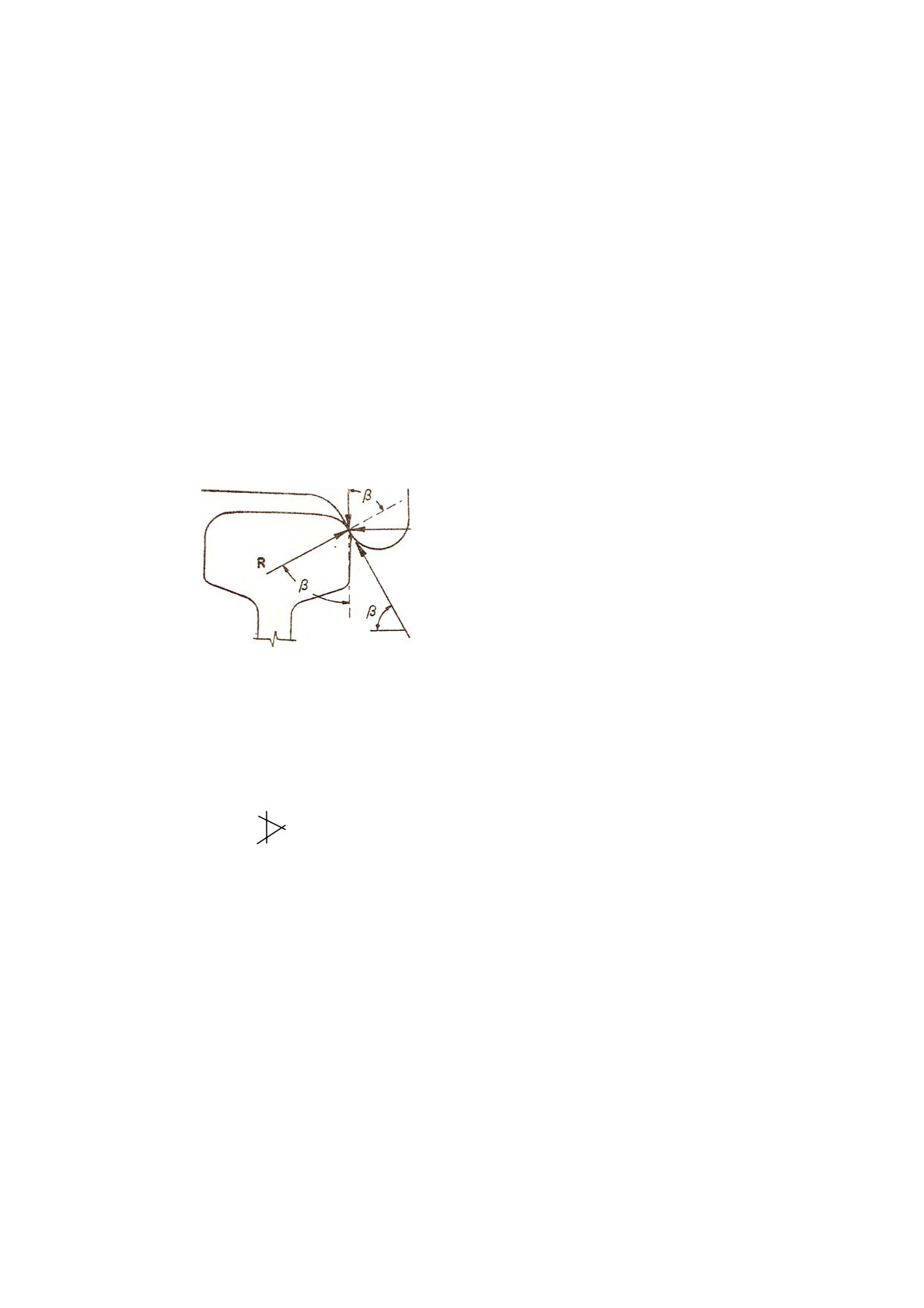
the arrangement of forces is as follows: -
Q
Y
μR
In the above figure different forces shown are as follow:
Q: Instantaneous wheel load
R: Reaction of rail
Y: Lateral thrust (flange force)
μR: Frictional force between rail and wheel flange (acts upward)
μ: Coefficient of friction
β: Flange angle
From the above simple model, following formula was derived by Nadal in 1908:
Y/Q
tanβ -μ/1+μ tanβ
The ratio Y/Q is called derailment coefficient.
(While investigating into derailment, all track vehicle defects and features and operational aspects
which cause one or more above mentioned factors to occur should be listed as possible contributory
factors. The list of such contributory defects and features thus arrived at should be arranged in
descending order of their assessed contribution. Thus one can arrive at one or more causes of
derailment.)
Type-2 When the wheel derails without any mark on the rail table.
In such type of derailments no flange marks are found on the rail table, In majority of such derailments
following reasons may have caused the accident:
•
Obstruction in the path of wheel.
•
Breaking of vehicle suspension arrangement.
•
Jamming of wheel due to roller bearing failure.
•
Mishandling of train by loco pilot
•
Wrong marshalling of vehicles with no brake power kept together or heavy vehicles in
the rear.
For investigation of such derailments the accident site must be carefully inspected for foreign body,
which might have caused obstruction to the derailed wheel. Examination of train brake power, position
of zero brake power vehicles and heavily loaded vehicles must be critically done. Additionally, loco
speedometer chart must be checked for last brake application.
Type-3 When the wheel derails with single flange mark on the rail table.
This is the most interesting category of derailment and requires detailed examination of track,
vehicles, loading condition and train operating conditions. First the wheel mount mark itself has to be
properly ascertained. The length of flange mark gives a clue to reasons for derailment. The following
factors must be considered after seeing the flange mark:
•
Long flange mark suggests that the wheel load reduced considerably for a long
period.
•
Short flange mark suggests that the lateral thrust increased to a considerably high
value.
•
The weight of the vehicle and speed of the train at the time of
accident affect the impression of flange mark on the rail.
In a number of cases an empty derailed wagon had been pulled to a very long
distance and the wheel mount mark was found but disputed due to ignorance of the investigating
officials. In all the cases, one must ascertain the first wheel drop mark and then trace back the mount
mark. After locating the mount mark, next step is to match it with the wheel that derailed first. For this
matching of damages on sleepers and position of vehicles after derailment will have to be done.
After identifying the point of mount and drop, detailed examination and recording of
track geometry rolling stock parameters, condition of loads in derailed as well as non-derailed vehicles
and operating conditions has to be done. This record reveals reasons for the accident. The analysis
has to be done with a view to find out reasons for increase in thrust and reduction in instantaneous
wheel load.
Type-4 When a number of wheels derail with several flange marks on the rail table.
In this category of derailment the probable reasons for derailment can be as follows:
•
Obstructions in the path of wheels.
•
Disturbed track (work being done on the track or sabotage)
•
Rail failure
•
Serious track defect-twist misalignment or formation failure
•
Buckling of track
In such cases, if there is no obvious reason like obstructions or rail failure, track
parameters are of particular relevance and sufficient care has to be taken in recording them. Readings
of track geometry is of great importance in establishing the behaviour of vehicle just before the
derailment. In addition to the readings taken after derailments, records of previous maintenance (rail
renewal, de-stressing etc.) must be perused to assess the amount of work done in the last few days.
DERAILMENTS AT POINTS AND CROSSINGS:
Points and crossings are meant for changing the road of a train and it has some discontinuities
thereby making it a weak link in track structure. In a point there are two tongue rails connected
together by stretcher bars and this assembly is called switch. A pull rod from some distance operates
this switch. Today, most of the points are operated by motors and they have some interlocking
arrangement. The interlocking for motor operated points is done with a lock bar and it has a detection
device also to detect proper housing of points.
Tongue rails forming the switch are hinged onto the heel blocks in the rear. The bolts,
provided for hinging the tongue rails, are kept loose for easy operation of switch. After the switch
arrangement, another important part is the nose of crossing. Here all the wheels traverse the path
shown by the switch.
Most of the derailments at points and crossings either initiate at the toe of the tongue rail or
near the nose of the crossing. Whenever a derailment takes place on a point the following checks
must be done:-
Gauge of point must be checked at four locations:
•
305 mm in advance of nose of tongue rail
•
152 mm inside the tongue rail for straight road and turn out.
•
At heel for tongue rail for straight road and turn out.
•
At middle of tongue rail for straight road and turn out.
The Gauge must be correct at all places except at the toe where it may be 6 mm slack for
housing the tongue rail.
It can be appreciated that conditions created by slack gauge' are not permitted near the
switch. IRPWM-1985, Para 237 t' (8) (a) and (b) is reproduced below:
“(8) Gauge and Super-elevation in turnouts-(a) It is a good practice to maintain uniform gauge
over turnouts.
(b) If gauge of track adjoining the points and crossings is maintained wider/tighter than the gauge on
the points and crossings. the gauge on the adjoining track must be brought to the same gauge as in
points and crossings and run out at the rate of I mm in 3 metres to the requisite extent. It should,
however, be ensured that the same gauge as applicable to the points and crossings is maintained for
at least one rail length on either side of point and crossings."
In case of derailment suspected to have started near the switch of the turnout the following
points need to be carefully examined:
•
The condition of tongue rail-whether broken, chipped or bent.
•
Whether the damage is old or new.
•
Height of the tip of the switch from top of stock rail.
•
Thickness of the tongue rail
•
Any gap between the tongue rail and stock rail
•
Any damage to stretcher bar
•
In case of interlocked points, the slackness between the locking bar slot and slide
should be recorded
•
The condition of brackets holding the stock rail
•
Whether the switch jumps up when a wheel passes on its heel.
If the derailment is suspected to have started near the crossing the following points must be
carefully checked:-
•
Condition of nose-wear, breakage, chipped, bent
•
Reduction in the level of nost as compared with wing rails.
•
Clearance between wing rail and stock rail (near the nose) on
both sides.
•
Clearance between guard rail and stock rail
•
Alignment of turnout to be measured for checking smoothness (with 6 metre chord at
1.5 metre intervals)
IRPWM has specified a check-list for complete examination of points and crossings.
There is one potentially dangerous structure called diamond crossing, which is generally not
provided on the main line. A simple diamond crossing has four noses (two acute angle and two
obtuse angle), which require a critical watch. Even a slight damage to these noses or disturbance to
the clearance between stock rails and guardrails make this diamond crossing unsafe. The problem is
further compounded if a diamond crossing has one or two slips also. The curvature of the slip is
generally so high that these structure are not fit for speeds above 8 to 10 kmph. It is advisable to
avoid use of these structures.
Some Important Defects
(A)
Permanent Way
•
Spread gauge
•
Gaping in points
•
Tipping of the toe of switch
•
Worn out & broken tongue Rail
•
Excessive clearances of check rail opposite to the nose of the crossing
•
Loose or slack points connections
•
Sharp curves with kinking alignments
•
Worn out Rails
•
Abrupt introduction of super elevation
•
Super elevation not corresponding to speed of the train
•
Buckling of track
•
Shearing of fish plate bolts
•
Subsidence of track
•
Uneven Cross level
•
Condition of Ballast
•
Security fastening deficient/loose
Track defects have a vital role in the accident and therefore it is very essential to
check the various parameters of the track. The following parameters must be checked thoroughly to
pin point the defects in the track:
(1)
Gauge - It is the shortest distance between the two rails of the track.
Rail Gauge
The standard gauge is 1676 mm.
Permissible Variations
• Straight line 6 mm tight to 6 mm slack ± 6 mm)
•
On curve with radius 350 Mtrs or more-6 mm tight to 15 mm slack (-6 to +15)
•
On curve with radius less than 350 Mtrs-Slack up to 20 IllIl1 (correction slip No. 10 Rly
Bd. L.No. 94/CE/II/TSG/I Dt. 20/24-6-96 of P. Way, manual)
•
Gauge sleeper to sleeper Variation -- 2 mm
IRPM Para 316(2) (a)
Cross-level of the track is relative level difference between the two rail tables
measured perpendicular to the track at the same point. It includes the variation in the super elevation
in case of curve cross level to be recorded on every fourth sleeper or 3 mts apart. The cross level
reading helps in calculating the TWIST available in the track. TWIST is calculated in mm/meters by
using the formula
Algebraic difference of cross level at two points A & B in mm divided by Distance
between points A & B in meters,
Ref. IRPWM - Para 316 (2) (C)
Twist should not be more than 3 mm/mt as per Railway Board letter no. 631W6/TK/I0/Dt
10.11.1964.
(3) Unevenness
This defect of the track is not reflected in the gauge and cross level reading. Low
joints, high joints, loose packing, sleepers and lifting of sleepers cause this defect. Long sags are not
taken as unevenness. It is recorded for left and right rail separately. It is measured in terms of
difference in longitudinal levels over' a fixed base. Unevenness gives rise to forced oscillations in a
vehicle and can cause variations in the values of instantaneous Wheel load and lateral thrust. Para
607 of IRPWM classifies unevenness (measured on 3.6 Mts cord) above 15111m as category D.
(4) Versine and super elevation
Versine and super elevation are measured for checking correctness of a curve. At the
beginning and at the end of the curve, details of the curve are mentioned on the board. Radius of any
curve is obtained by dividing 1750 mtrs, by its degree. Versine is calculated as:
V= 125.C2/R
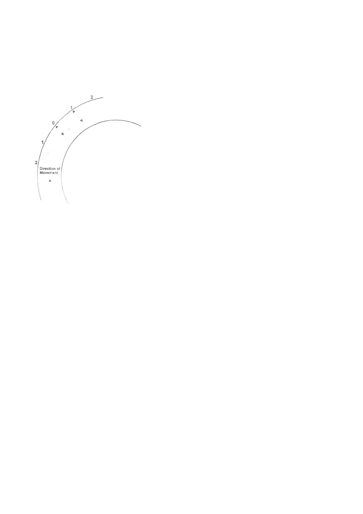
R - Radius in meters
C - Cord length in meters
V - Versine
As per Para 421 (b)(i) of IRPWM, the station to station variation of versines of stations 10 Mts
apart should not exceed 15 mm for more than 100 Kmph speed, whereas for speeds 100 Kmph or
less than 100 Kmph it should not exceed 20 mm or 200/0 of the average versine of the circular portion
whichever is more.
The super elevation is calculated as:
C = GV2 /127R
C = Cant/Super elevation in mm.
G = Dynamic gauge in mm
V= Speed in Kmph
Para 406 ( d) of IRPWM specifies a maximum cant of 165 mm. on group A, Band C routes
and 140 mm on group D and E routes. The maximum amount of cant deficiency is also specified in
para 406(2) as given below :
•
For speeds in excess of 100 Kmph on group A and B routes for nominated
rolling stock and routes with permission of Chief Engineer - 100 mm
•
For broad gauge routes not covered by above - 75
(5)
Ballast
It is a very important member in the track structure. It helps in maintaining track Geometry.
The ballast resistance is affected by following factors -
Ballast - Size, Material, Shape, State of consolidation, Type of sleeper, Cushion at Formation.
Para 263(2) I RPWM recommends the Minimum depth of ballast below the bottom of the
sleeper at rai I seat as under:
Groups
Recommended Depth
BG Group A
300 mm
BG Group B & C
250 mm
BG Group 0
200 mm
BG Group E
150 mm
(6) Rail
The accident caused by rail fracture does not leave much room for investigation. The
fractured rail is to be tested to find out the nature of the failure. The visual inspection can reveal
whether the fracture was new or there was some old flow in the rail.
For other derailments, the rail is measured for its wear. The rail wears out mostly on the top
surface and gauge face. Rail wear can be vertical, lateral or angular.
Angular wear
Profile of new rail
Vertical Wear

Worn profile
The limits of wear of rail have been laid down in IRPWM Para 302 (b)
Gauge Rail section
ertical wear
B.G.
60 kg/meter
13mm
52kg/mctcr
8mm
90R
5mm
Lateral wear limits have been given in para 302 (b)
Section
Gauge
Category of work
Lateral wear
Curves
B.G.
I Group A & B routes
8 mm
Curves
B.G.
I Group C & D routes
10 mm
Group A & B routes
6 mm
Straight
B.G.
,Group C & D route
8 mm
(7) Sleepers
If sleeper suffer any damage or loss in property, it can cause derailment. While recording the
gauge and level readings the condition of each sleeper must be carefully sleepers near point of
mount.
(8) Rail Fasteners
For different - type of sleepers, the rail fasteners are different Wooden sleepers - Dog spikes,
Round head spikes, Steel keys Steel trough sleeper - steel keys
Prestressed concrete sleepers-- elastic clips with liners between the foot of rail and clip.
Condition of all fasteners should be recorded while taking track reading
(9) Creep
This is a silent but very dangerous phenomenon of the track. Creep is a longitudinal
displacement of track and is caused by
•
Temperature variation causing expansion and contraction of the rail.
•
The tractive forces of locomotive to push the rail backward.
•
Braking forces of train trying to push the rail forward. The effect of the above forces is
accelerated if the rail fasteners are not able to hold the rails properly to the sleepers or rail seat on the
sleepers is a damaged or bad joint in the track with out proper expansion gap.
Para 242 (6) of IRPWM specifies maximum about of creep permitted as 150mm. In LWR and
CWR creep indication point are provided at a distance of 50 meters and 100 meters SEJ(Switch
Expansion Joint) on either end of LWR/CWR.
(10) Buckling
When a section of track buckles, about one or two rails length of the track leaves its place and
moves side way. This also happens due to the rise in temperature and other reasons similar to the
creep. The buckling may be horizontal or vertical. Buckling normally happens in the 2nd half of the day
mostly, when the track has absorbed max. heat and also near the bridges, level crossings etc. where
the track is firmly held in ground.
(B) Defects ofRolling Stock
•
Defects in wheel and Axle Broken & Hanging fittings
•
Defects in Bolster and Assemblies
•
Defects in spring gear, axle guard and trolley
•
Defects in Brake gear
•
Excessive Clearance in side bearer, pivot etc.
•
Hot box/Roller bearing failure
•
Under frame and under frame members out of alignment
•
Poor brake power
•
Broken or disengaged Baffle plates in the empty/unloaded tank wagons
•
Defective Draw gear, CBC gear and Buffing gear, Train parting & subsequent-collision -
‘alliance 2’ - couplets opening automatically.
Defects of Locomotives are very similar to defects of Rolling Stock
CONCEPTS OF ELECTRIC TRACTION (Back to Index)
Power Supply
25 kV, ac, 50 Hz single phase power supply for electric traction is derived from the grid
system of State Electricity Boards through traction sub-stations located along the route of the
electrified sections at distances of 35 to 50 km apart. The distance between adjacent sub-stations
may however be even less depending on intensity of traffic and load of trains.
Sectioning of OHE:-
To ensure rapid isolation of faults on the OHE and to facilitate maintenance work the OHE is
sectioned at intervals of 10 to 15 km along the route. At each such point a 'switching station
interruptors' usually rated at 600A are provided. The shortest section of the OHE which can be
isolated by opening interruptors alone is called a 'sub-sector'. Each sub-sector is further sub-divided
into smaller 'elementary sections' by provision of off-load type manually operated isolator switches.
At some stations with large yards, alternative feeding arrangements are provided so that the
power for feeding and yards may be drawn from alternative routes. Normally the switch is locked in
one position, being changed to the other when required after taking necessary precautions.
To meet requirements at electric loco running sheds, isolator with an earthing device in the
'off position is provided. At watering stations manually operated interrupters and isolator with earthing
heels are provided to enable switching off of the power supply locally and earthing the OHE to enable
working on roofs of rolling-stock. There are several types of switching stations as detailed in the
following paras.
Feeding Post (FP): It is a supply control post, where the incoming feeder link from grid substation are
terminated.
Each feeder supplies the OHE on one side of the feeding post through interrupters controlling supply
to the individual lines. Thus, for a two track line, there will be four interrupters at each feeding post.
Sectioning and Paralleling Post (SP)
These posts are situated approximately midway between feeding posts marking the demarcating
point of two zones fed from different phases a ‘paralleling interrupter’ is provided at each 'SP' to
parallel the OHE of the up and down tracks of a double track section, 'bridging interrupters' are also
provided to permit one feeding post to feed beyond the sectioning post upto the next FP if its 25 kV
supply is interrupted for some reasons. These bridging interrupters are normally kept open and should
only be closed after taking special precautions as detailed in these rules.
Sub-Sectioning and Paralleling Post (SSP)
One or more SSPs are provided between each FP and adjacent SP depending upon the distance
between them. In a double track section, normally three interrupters are provided at each SSP i.e. two
connecting the adjacent sub-sectors of up and down tracks.
Sub-Sectioning Post (SS)
These are provided only occasionally. They are similar to SSPs with provision for sectioning of the
OHE but not paralleling.
Neutral Section: It is a short section of insulated and dead overhead equipment which separates the
area fed by adjacent substation or feeding post.
A neutral section is provided to make it impossible for the pantograph of an electric locomotive or
EMU train to bridge the different phases of 25 kV supply, while passing from the zone fed from one
sub-station to the next one. Since the neutral section remains 'dead', warning boards are provided in
advance to warn and remind the Loco pilot of an approaching electric locomotive/EMU to open
locomotive circuit breaker (DJ) before approaching the 'neutral section', to coast through it and then
switch 'on' on the other side. Special care is taken in fixing the location of neutral sections, on level
tangent tracks far away from signals, level crossing gates etc. to ensure that the train coasts through
the neutral section at a sufficiently high speed, to obviate the possibility of its stopping and getting
stuck within the neutral section.
Other Important Equipment at Switching Stations
Certain equipments are installed at various points to protect the lines, to monitor the availability of
power supply and provide other facilities. These are generally as under:
1.
Lightning arresters are provided to protect every sub-sector against voltage surges.
2.
Auxiliary transformers are provided at all the posts and also at certain intermediate points to
supply ac at 240 V, 50 Hz required for signalling and operationally essential lighting installations. To
ensure a fairly steady voltage, automatic voltage regulators are also provided where required.
3.
Potential transformers are provided at the various switching stations for monitoring supply to
each sub-sector.
4.
A small masonry cubicle is provided to accommodate remote control equipment, control
panel, telephone and batteries and battery chargers required for the control of interruptors and other
similar equipments.
OVERHEAD EQUIPMENT
Catenary and Contact Wires
1.
The overhead equipment above the tracks comprises of the following: -
a)
A stranded cadmium copper wire of about 65 mm2 section or
stranded
aluminium alloy wire of about 116 mm2 section for catenary.
b)
A grooved hard drawn copper contact wire of 107 mm2 cross-section (when new)
supported from the catenary by means of droppers of 5 mm diameter spaced not
more than 9 m apart.
2.
The catenary and contact wire together have an equivalent copper section of 157 mm2. The
current normally permissible on a single track is 600 A approximately, because of equivalent cross-
sectional area of OHE. This current limit is based on the temperature limit of 85°C in contact wire.
Certain sections in Waltair-Kirandul section have the catenary and contact wires together having an
equivalent copper section of 200 mm2.
3.
For loop lines, sidings, yards and spur lines excluding the main running lines and first loop or
lines taking off from main running line, tramway type OHE having only grooved hard drawn copper
contact wire of 107 mm2 section is provided.
Height of Contact Wire
The normal height of contact wire for regulated OHE is 5.60 m (with 10 cm pre-sag for 72 m
span) above rail level. For unregulated OHE in areas with a temperature range of 4°C to 65° C, this
figure is 5.75 m and in areas with a temperature range of 15 °C to 65 °C, it is 5.65 m. In certain cases,
such as under over-line structures, the height may be as low as 4.65 m on BG and 4.02 m on MG. For
passing oversize consignments on such lines, special precautions have to be taken.
Span of Supporting Mast/Structures
The span normally used for supporting the OHE from masts/structure using the cantilever
type bracket assembly varies from maximum 72 m on straight track to 27 m on curved track, the
spans depending upon the degree of curvature. The catenary system is normally supported on
straight tracks at maximum intervals of 72 m (63 m on MG) by cantilever type arms fixed to galvanized
broad flange or I section steel masts or fabricated steel structures. On curves the catenary is
supported at closer intervals, the spans adopted depending upon the degree of curvature.
Stagger
The contact wire is staggered so that as the pantograph glides along, the contact wire sweeps
across the current collecting strips of the pantograph upto a distance of 200 mm on either side of the
centre line on straight runs and 300 mm on one side on curves. This ensures a uniform wear of the
current collecting strips of the pantographs.
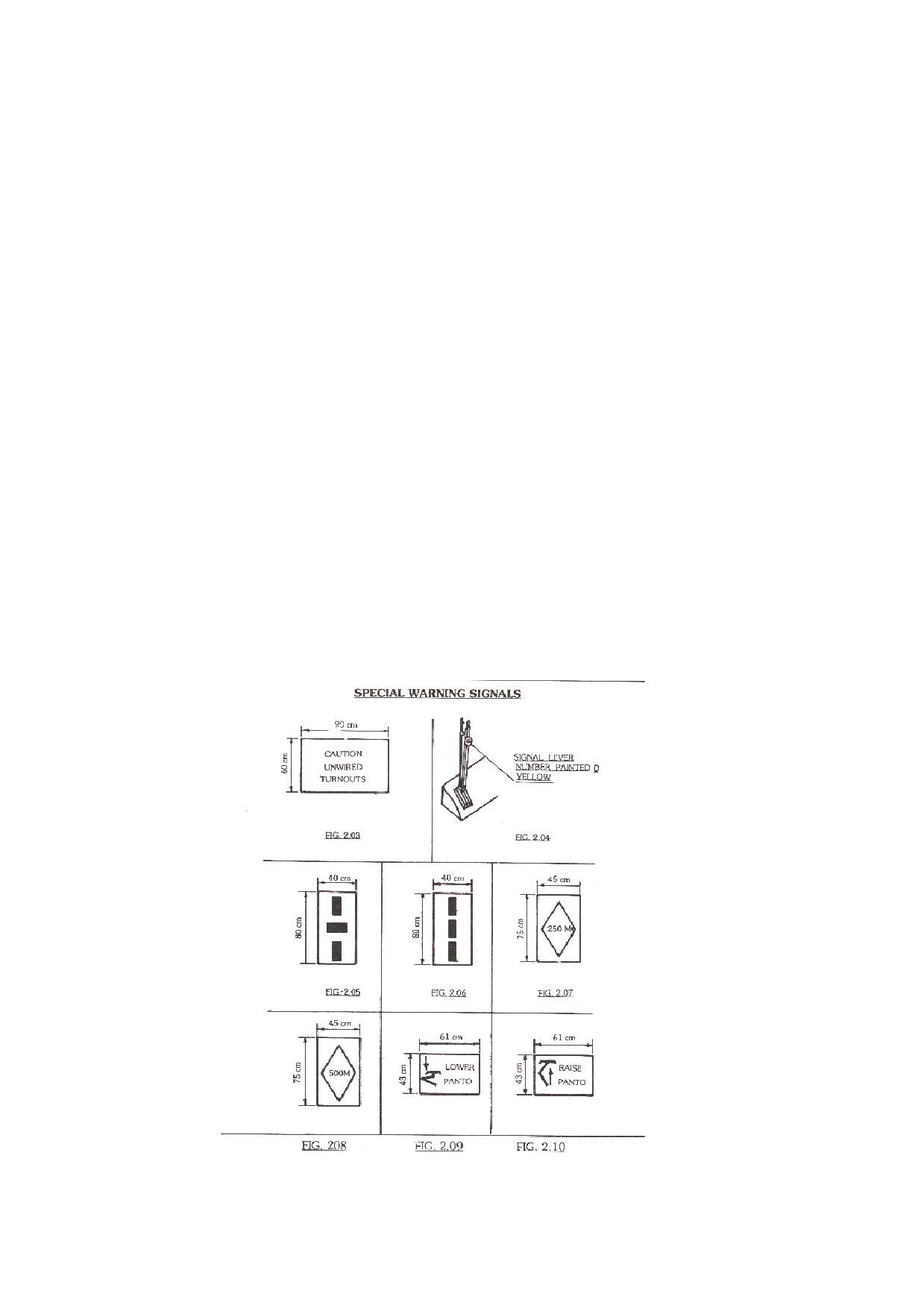
Overlaps: The OHE conductors are terminated at intervals of about 1.5 km with an overlap generally
as shown in Fig. 2.02, the conductor height being so adjusted that the pantograph glides from one
conductor to the other smoothly.
There are two types of overlap spans as under:-
a)
Uninsulated overlap spans where the distance of separation between two contact
wires is
200 mm and the two conductors are permanently connected together
electrically by suitable jumpers.
b)
Insulated overlaps, where the two OHE systems are kept apart at a distance of 500
mm. Normally the electrical discontinuity at insulated overlaps is bridged by
interrupters or isolator except at neutral sections.
Regulated and Unregulated OHE
OHE with automatic tensioning called 'regulated OHE' is generally provided for all main lines, but for
large isolated yard and unimportant lines, automatic tensioning is dispensed with in the interest of
economy and only unregulated OHE is used.
Section Insulator Assembly
Section insulators are provided to insulate the OHE of one elementary section from the OHE of the
adjacent elementary section such as at cross-overs. When the pantograph of a locomotive passes
from one track to another along a cross-over/turnout, current collection changes from one OHE to
other and therefore the runners of the section insulators overlap with contact wire so that there is no
arcing.
On double line sections with runners trailing, the section insulator assembly using porcelain insulators
are fit for speeds upto 120 km/h provided it is installed between the first one-tenth and one - third of
the span. In case the runners of the section insulator assembly are in the facing direction or it is not
installed within the first one third of the span, the speed should be restricted to 80 km/h.
GENERAL DESCRIPTION OF ELECTRIC ROLLING STOCK (Back to Index)
Classification of Electric Rolling Stock
Locomotives and Multiple Unit stocks are classified by means of a three/four letter code followed by a
number to indicate the individual class and a series of the same.
The code letters used for AC locos and EMUs are given below:
The first letter denotes the Gauge: 'W for BG and 'Y' for MG.
The second (middle) letters 'A' denotes the system of power supply for which it is suitable - A for AC &
C for DC, CA for DC & AC.
The third letter for locos indicates the class of service -
'M' for
mixed traffic locos suitable for both passenger and freight services,
'G' for Freight (Goods) service locos,
'P' for Passenger services locos, and
'S' for Shunting locos.
Multiple Unit Stock is denoted by the letter 'U'.
The various classes of ac locos and EMUs at present in service on Indian Railway are as under:-
(a)
AC Locos— WAG1, WAG2. WAG3, WAG4, WAG5, WAG6, WAG7, WAG9WAG9M
(b)
WAP1, WAP2, WAP3, WAM1, WAM2, WAM3, WAM4, WAP4, WAP 5, YAM1
(c)
(b)
AC/DC Locos— WCAM1,
(d)
(c)
AC EMUs— WAU1, WAU2, WAU3, WAU4, YAU.
In addition two types of BG DC EMUs converted for AC working are in use on the Eastern Railway.
Important Equipment of Electric Loco/EMU
Pantograph
For collecting power from 25 kV ac contact wire pantographs are mounted on the roof of the traction
vehicles. AM 12 pantograph of Faively design has been adopted by Indian Railways for 25 kV ac
electric locomotives and EMUs. These pantographs are provided with steel strips for current
collection. The raising and lowering of the pantograph is by means of a pneumatically operated servo
motor. This pantograph is a single pan design having two o-springs mounted on it. For keeping the
pantograph in the lowered condition, main springs have been used. The suspension of pan is on
plungers.
This pantograph is suitable for operation upto 140 km/h. For increasing the speed potential, improved
pantograph with lower dynamic mass and independent pan heads have been used. Further, in order
to improve the life of the contact wire, use of carbon strips has also been tried. Use of carbon strips for
current collection has already been adopted in European countries.
Use of carbon strips necessitates change in the design of the pantograph; the pan head which is more
or less rigid in case of steel strip pantograph needs to be made more flexible in the vertical, horizontal
and transverse movement for carbon strip pantographs. This is achieved by improved suspension of
the pan head. The speed potential of such a pantograph is of the order of 250 km/h.
2. Circuit Breaker
-- Air Blast Circuit breaker
-- Vacuum Circuit breaker
These breakers are designed for isolation of power to the traction vehicle in the event of faults.
Vacuum Circuit Breakers were introduced on electric locomotives on Indian Rlys. in the year 1985.
The VCB is a simplified design with fewer number of parts (260 Nos.), have a simplified control block
and self - contained interrupting medium that is vacuum. Due to these features, the life of the main
contact achievable is as high as 1 lakh electrical operations as against 20,000 operations for air blast
circuit breakers. As a result, the periodicity of replacement of main contact is second POH for VCB
and IOH for Air Blast Circuit Breakers. Besides, these factors, VCB also offers the advantages of
reduced size, reduced weight and reduced maintenance cost as compared to these for air blast circuit
breakers. The total trip-time for VCB is less than 60 milli-seconds while the same is of the order of 100
milli-seconds for air blast circuit breakers. The air blast circuit breaker is only capable of breaking the
fault current with breaking capacity of 250 MVA. The VCB, besides having breaking capacity is also
designed for making capacity of the same rating, i.e. 250 MVA and can handle the same level of fault
current during closing also.
3. Transformer
Power to the traction vehicles is available at 25 kV ac single phase from the contact wire. In order to
step down the voltage as well as to control the same for feeding to the traction motors, the traction
power transformers are provided on the traction vehicles.
These transformers generally have a primary winding, a regulating winding, traction secondary
windings and auxiliary windings. The regulating winding is designed for choosing appropriate voltage
for the traction motors. The auxiliary winding is required for feeding the auxiliary motors on the
locomotive.
In order to increase the h.p. of the locomotives, the traction transformers have been uprated from time
to time keeping the overall dimensions unchanged on account of space constraint. The upratings
have been achieved by using increased copper section of the conductor used, improved insulation
scheme and in certain cases adoption of aluminium foil wound construction for minimizing the losses.
With the introduction of thyristorised converters, the design of the traction transformer has undergone
simplification with the deletion of regulating winding. The transformer for thyristorised converter
becomes a two limb construction and traction secondary winding split into 4 windings for two step
sequence control.
The traction transformer necessarily has to have forced oil circulation and forced air cooling. For this
purpose oil pump, oil cooler and blower form an integral part of the traction transformer.
Tap Changer
Tap changer is provided on 25 kV (HT) regulating winding of locomotive transformer for controlling the
voltage input to main transformer.
Traction Motor
In case of traction motor great emphasis is being given on improving power to weight ratio, keeping in
view the limited space available on locomotive for mounting the same. There is continuous effort to
improve the performance of traction motor by making them lighter/compact, at the same time more
reliable. Indian Railways have been adopting the latest technology available for design and
manufacture of traction motor. Over a period of years the traction motors have become now 2.5 times
lighter specially for EMU application.
Arno Converter
Arno Converter is a special duty machine for conversion of single phase in-coming supply into 3
phase out- put supply. 3 phase supply is essentially required on most of the electrical locomotives for
driving certain auxiliary equipment like blowers and compressors. The function of Amo Converter is to
supply 3 phase power required for these auxiliaries.
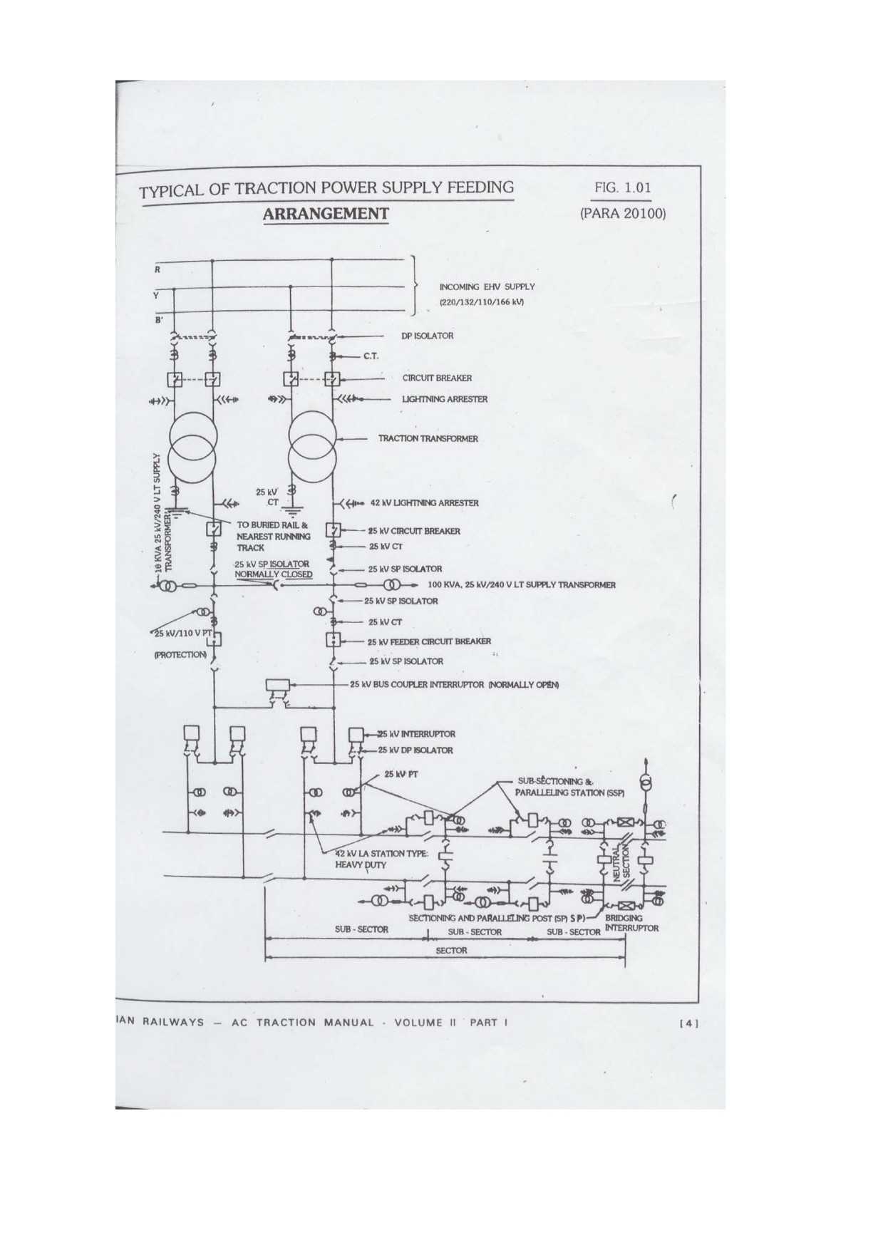
CREW LINKS, LOCO LINKS AND POWER PLAN
(Back to Index)
PROCEDURE FOR CALCULATING CREW REQUIREMENT OF A DIVISION
1.
Running staff review should be carried out after every six months i.e. on 15t Jan. and 1st July
by STA (Senoir technical assistant) of the division.
2.
Before preparing review, loco pilot's links of all the sheds should be got prepared and vetted
by personnel branch.
3.
Statement of avg. hours on road and no. of goods
4.
Trains ran during last six months for each section should be ready duly approved by Sr.
DOM/DOM. A list of shunting' points and DMTs running to be prepared and signed by Sr. DOM/DOM.
5.
Mail/Express/Passenger Loco pilots requirement to be worked on the basis of loco pilots/crew
links.
6.
For goods crews_ the requirement should be worked out as per power plan signed by Sr
DME(P) and Sr. DOM. 7.67 Crews are to be demanded for one freight POL. Separate crews to be
demanded for the activities which cannot been covered in power plan e.g., Light engine and Empty
coaching rakes running etc.
7.
30% leave reserve and 10 % trainee reserve should be demanded for this additional
requirement.
8.
Shunters should be demanded @ 1 against 8 hrs. point. Also rest giver @ 1 for 6 shunters to
be demanded. Leave reserve and trainee post to be demanded separately.
9.
Requirement of DSL assistants should be same as that of loco pilots (Excluding motormen
where no assistant loco pilot is required).
10.
Running staff review duly signed by Sr. DME/Sr DEE should be put up to Sr. DAO for vetting.
11.
After accounts vetting sanction of DRM be taken and Sr. DPO will issue circulars of revised
sanction.
+ Running supervisors review should also be made with staff review @ 1 loco Inspector against 25
loco pilots or 50 shunters. No rest giver allowed. Leave reserve 12.5%.
POINTS TO BE KEPT IN VIEW WHILE PREPARING LOCO PILOT'S LINKS
1.
Loco pilot/Crew links are prepared by CPRC/CTLC and got verified from Personnel Branch.
Objective of crew links is to ensure optimum utilization of crews.
2.
Train timings to be checked from the latest timetable.
3.
Links to be prepared before promulgation of new time table.
4.
Max. duty hours in anyone trip should not exceed 10 hours.
5.
Avg. duty hours in a fortnight should not exceed 104 hours.
6.
Min. no. of rests in a month should be 5 of 22 hrs. or 4 of 30 hours including night in bed from
22 hrs. to 6 hrs. from sign off to sign on.
7.
Efforts should be made to include all the sections in the link to avoid giving learning road
again and again.
8.
Min. out of station rest in case less than 8 hrs. duty in the previous trip should be 6 hrs from
sign off to sign on. In case duty is 8 hrs or more than 8 hrs, then 8 hrs. rest to be given. In case of
short trips of less than or equal to 5 hours then duty performed plus 1 hrs. will be sufficient.
9.
Min. home station rest should be
(a)
If duty performed in the last trip is less than 8 hrs., then 12 hrs.
(b)
If duty is 8 hrs. or more. then 16 hrs.
(c)
If staff is required to work train less then stipulated rest then breach of rest allowance
is payable to running staff.
10.
Link having the maximum earning kilometerage should be worked by senior most loco pilots
and so on.
11.
Separate links should be prepared for superfast trains such as Rajdhani/Shatabdi Exp.
Chronic late running trains should be kept in view to avoid link failures.
POINTS TO BE KEPT IN VIEW WHILE PREPARING LOCOMOTIVE LINKS
1.
Loco/Power links are prepared by HQ.'s office and circulated to the divisions. The objective of
power links is to ensure optimum utilization of powers.
2.
Train timings should be checked from latest time table.
3.
Links to be prepared before commencement of new time table.
4.
Efforts should be made to send the loco to home shed for servicing within the stipulated
schedule time
5.
Minimum possible out station halt should be provided.
6.
Ensure loco is permitted to run on the sections at the max. permissible speed of the train.
POWER REQUIREMENT (POWER PLAN)
(A)
1.
To be prepared once in six months.
2.
Avg. No. of trains run on each section per day and Avg. hours on road for last six months duly
signed by Sr.DME(P) and Sr.DOM to be prepared.
3.
Formula: Section wise average freight POL for the last six months to be calculated as under:
Bare POL = PDD + HOR + PAD
(POL=Power on line ; PDD = Pre departure detention; HOR=Hours on road; PAD=Post arrival
detention)
4.
3.5 % further growth and 10% Bunching allowance to be demanded on Bare POL
5.
Loco's requirement. for DMT. ART. and other loco' s which remain in outage but not added in
POL for the purpose of calculation of average kilometers to be added in the bare requirement.
6.
To arrive total POL. last six month average POL of shunting loco link WDS-4, WDS-5 pilots
and Mail lie over to be added in the POL calculated above.
7.
Mail/Exp./Pass. Loco requirement to be worked out on the basis of loco link. Add 10% for
major repair allowance.
8.
For shunting services, work out number of points for 8 hours shunting, demand 0.33 POL. Add
1 loco as overlap against 06 loco. Add 10% for major repairs.
9.
Kms formula: Total kms earned on the Avg. per day during last six months divided by average
loco utilization.

LOCO MAINTENANCE SCHEDULE (Back to Index)
(I) & (II) Conventional Locos
Coaching Locos (Railway Board Letter No.92/Elect
(TRS)/138/5 Pt. I, dated
18.01.2001
&
Railway Board Letter No.9/Elect (TRS)/138/5 Pt.II, dated 21.12.001)
Maintenance
Periodicity
Duration
schedule
Trip Inspection(TI)
After 3000 kms or one trip, whichever is later
2 hrs
IA
40 + 3days.
4hrs
IB
80 + 3days
6 hrs
IC
120 + 3days
8 hrs
AOH
12 months + 15 days
6 days
36 months + 1 month or 4(6 lakh for wAP-1/4 loco) lakh kms.
IOH
whichever is earlier
9 days
6 years+ 3 months or 8 lakh kms. (12 lakh for WP-1/4 loco)
POH
28 days
whichever is earlier.
Freight Locos
Railway Board Letter No.92/Elect (TRS)/138/5 Pt. I, dated 18.01.2001)
Maintenance
Periodicity
Duration
schedule
15 days (Fitted with TAO TMs)
Trip Inspection(TI)
2 hrs
(20 days (fitted with Hitachi TMs)
IA
45+ 3 days
4 hrs
IB
90+ 3 days
6 hrs
IC
135+ 3 days
8 hrs
AOH
18 months + 10 days
6 working days
54 months + 1 monthy or 6 lakh kms whichever is
IOH
9 working days
earlier
POH
9 years + 3 months or 12 lakh kms whichever earlier
28 working days

(iii) 3-Ph.ABB Locomotives
(Railway Board Letter No.97/Elect (TRS)/440/18/44 (3Ph,
dated 23.02.07)
Coaching Locos (WAP5/WAP7 Locos)
Maintenance
Periodicity
Duration
schedule
Trip Inspection
3000 kms or one trip, whichever is later
2 hrs
IA
90 days.
6 hrs
IB
180 days
6 hrs
IC
270 days
8 hrs
MOH
18 months
6 working days
4.5 years + 6 months or 12 lakh kms. whichever
IOH
11 working days
is earlier
9 years+ 6 months or 24 lakh kms. whichever is
POH
28 working days
earlier.
Freight Locos
(WAG9/WAG9H Locos)
Maintenance
Periodicity
Duration
Schedule
Trip Inspection
45 days
4 hrs
IA
90 days
6 hrs
IB
180 days
6 hrs
IC
270 days
8 hrs
MOH
18 months
2nd MOH
6 years + 6 months or 12 lakh kms. whichever is
IOH
11 working days
earlier.
12 years + 6 months or 24 lakh kms. whichever
POH
28 working days
is earlier

DIESEL LOCO SCHEDULE & DURATION
WDM3A/B/C/D
WDG3A
Schedule
WDM2
WDM3A/B/C/D
WDG3A
WDP1/3A
Duration
(30 days)
(30 days)
T-1
15 days
20 days
20 days
As per link
4 hrs.
Trip - 30 days
Trip-30 days
T-2
30 days
40 days
40 days
30 days
6 hrs
M-2
2 Months
2 Months
2 Months
2 Months
2 Months
2 Months
8 hrs
M-4
4 Months
4 Months
4 Months
4 Months
4 Months
4 Months
16 hrs
M-12
12 Months
12 Months
12 Months
12 Months
12 Months
12 Months
4 days
M-24 MOH)
24 Months
24Months
24 Months
24 Months
24 Months
24 Months
16 days
M-48 (IOH)
48 Months
48 Months
48 Months
48 Months
48 Months
48 Months
21 days
M-96 (POH)
96 Months
96 Months
96 Months
96 Months
96 Months
96 Months
30 days
ELECTRIC LOCOMOTIVE FEATURES
S.No.
Description
WAM4
WAP1
WAP4
WAP5
WAP6
WAP7
WAG5
WAG5
WAG6
WAG7
WAG9
WAG9
WCAM1
WCAM2
WCAM3
WCAG1
WCM5
WCG2
A/B
HA/HB
H
1
Supply System-AC(kV)
25
25
25
25
25
25
25
25
25
25
25
25
25/1.5
25/1.5
25/1.5
25/1.5
1.5 DC
1.5 DC
DC
DC
DC
DC
2
Continuous HP
3640
3800
5000
5440
5060
6120
3850
3850
6000
5000
6120
6120
3640/
4715/
5000/
5000/
4600
4200
2930
2916
4600
4600
3
Max. Speed (kmph)
120
130
140
160
160
130
80
80
120
100
100
90
120
120
105
100
105
80
4
Starting Tractive Effort (Tonnes)
33.8
22.4
32.4
26.29
30.8
32.88
33.5
33.5
46
44
46.89
52
33.84/
33.5/
40.2/
43.5/
39.6
35.6
23.2
26.0
26.8
30.0
5
Continuous Tractive Effort
56
13.8
18.8
22.42
19
23.23
20.6
20.6
32
27
33.12
46
16.8/
23.8/
26.8
31/30
27
30
(Tonnes)
22.6
24.6
6
Total Weight
112.8
108.3
112.8
78
113.2
123
118.8
118.8
123
123
123
123
112.8
117
121
128
120
132
7
Braking
D
D
A
A,R
A
A,R
D
D
A
A
A,R
A,R
D
D
D
D
D
D
8
Bogies Arrangment
Co-Co
Co-Co
Co-Co
Bo-Bo
Co-Co
Co-Co
Co-Co
Co-Co
Bo-Bo-Bo
Co-Co
Co-Co
Co-Co
Co-Co
Co-Co
Co-Co
Co-Co
Co-Co
Co-Co
9
Bogies Type
Cast
Cast
Flexi
Fab.
Flexi
Cast
Cast
Cast
Flexi.
Fab.
Fab.
Fab.
Cast
Fab.
Fab.
Fab.
Cast
Cast
10
Gear Ratio
15.62
21.58
23.59
17:35:67
23.58
20.72
17.77/
18.64
16.63/
16.65
15.77/
21.107
16.61/
15.62/
18.64
16.65
18.64
18.74
15.62
20.75
21.107
21.58
21.58
11
No. of Traction Motors
6
6
6
4
6
6
6
6
6
6
6
6
6
6
6
6
6
6
12
Traction Motor
TA-
TA-
TA-
6FXA-
HS-
6FRA-
TAO-
HS-
ASEA-
HS-
6FRA-
6FRA-
TAO-
TAO-
TAO-
HS-
HS-
TM-
O659
O659
O659
7059
15250A
6068
659
15250A
L3M450-2
15250A
6068
6068 HT
659
659
659
15250A
15250A
4939 A2
13
Axle Load
18.8
18.05
18.8
19.5
18.9
20.5
19.8
19.8
20.5
20.5
20.5
20.5
18.8
19.5
20.2
21.3
20
22

DETAILS OF BRAKE POWER CERTIFICATE
Brake Power%
S.No
Type of train
Validity
Originatin
En-route
Conditions for invalid BPC & Other instructions
g station
station
1
Ordinary End
Examination-Loading-
85-
75
The BPC will become invalid, if -
to End Rakes
Unloading-
Vacuum
i) No destination mentioned on the BPC of Loaded
Vacuum brake
Examination, ie., one
brake
train
rake, Air
time loading
stock 90-
braker rake
Air brake
ii) Empty rake does not reach loading point within 04
other than
stock
days (for Vacuum brake stock)
Premium
iii) Train composition is changed by 10FWUs or Four
8 wheeled wagons or more
iv) Train is stabled more than 24 hours in examination
yard.
2
Premium Air
12 days for multiple
Minimum
Not
The BPC will become invalid, if -
brake Rakes
loading, i.e., loading to
95
mentioned
VOXN, BCN,
be done within 12
i) Rake integrity is disturbed by more than Four 8 -
BRN, BOBRN,
days +3 days grace
wheeled wagons
etc.
period in loaded
ii) Train is stabled more than 24 hours in examination
condition.
yard
Instructions for Premium End to End rakes:
i) After lapse of
12 days, rake to be offered for
examination at the first nominated intensive
examination point in the direction of movement.
ii) After lapse of 15 days, rake either empty or loaded
shall be offered for examination at the first exam
point in the direction of movement
iii) Premium BPC shall be issued from the nominated
“A” category depot.
iv) Normal End to End BPC shall be issued if the rake
is not offered for examination in empty condition or
at nominated “A” category exam point.
v) After each loading/unloading, the rake shall be
subjected to GDR check
3
Close circuit
Premium CC rake -
100
90
The BPC will become invalid, if -
rakes only Air
7500 kms/35 days
i) Rake is not running in nominated circuit.
brake stock
whichever is earlier Or
ii) Rake is stabled more than 4 hrs at examination
6000 kms/30 days’
station.
whichever is earlier
iii) Rake has completed either stipulated Kms or days
(Some railways have
iv) More than
4 wagons are replaed between two
CC rakes of 6000
Periodical Maintenance Examination ie., PME
kms/30 days
whichever is earlier.
Instructions for Premium CC rakes:
C..Rly. does not have
i) Rake shall be offered at its Nominated “A” category
such rakes
base depot
ii) Rake shall be formed off POH/ROH wagons only
iii) After each loading/unloading, the rake shall be
subjected to GDR check
iv) BPC shall be revalidated by C&W staff wherever
TXR staff is provided
v) Wagons to be attached shall be good examined
wagons.
4
Container
6000 kms/0 days
100
90
The BPC will become invalid, if -
rakes
Circuits - TKD - JNPT-
j) Rake has completed either Stipulated Kms or days.
BLCA+BLCB
DADRI/TKD-
ii) Rake is not running in nominated circuit
JNPT/TKD/AQ depot
Instructions for Container rakes:
run on fre4e circuit
iii) Rake integrity is to be maintained
basis
iv) Revalidation of BPC by TXR staff after every
unloading/loading
v) Rake shall be formed from New wagons or Off
POH/ROH wagons
vi) Utilization of wagons in
6000 kms. Rake - New
wagons up to 12 months/Off POH/ROH wagons up
to 09 months.

Various Machines used for Track Maintenance
Minimum Stipulated Block Period
Maximum Stipulated
Type of
S.
Purpose of
Setting &
Output/Eff
Track
Deliverables
To & fro
Working
Minimum Ty. Speed
No
Deployment
winding up
Total
ectivehour
Machines
time (in*)
time
Restriction, if any.
time (in*)
(new m/c)
It corrects track geometry i.e.
alignment, twist, cross level,
Nil, except in summer
Plain Track
longitudinal level and pack
1
09-3X
15
10
3:35
4:00
1.6Km
with 50 kmph, if not
Tamping
ballast under sleepers. This
followed by DTS
machine can pack three
sleepers at a time.
Plain Track
DO. But can pack two sleepers
2
CSM
15
10
3:35
4:00
1.2 Km
do
Tamping
at a time.
DO. Generally deployed at work
Plain Track
3
UNO
site. But can pack one sleeper
15
10
3:35
4:00
0.5km
do
Tamping
at a time.
Plain Track
4
DUO (0)
DO. Generally deployed at work
15
10
3:35
4:00
0.8km
do
Tamping
site. But can pack two sleepers
Plain Track
5
WST
at a time
15
10
3:35
4:00
0.8 km
do
Tamping
20kmph or 40kmph if
Ballast
It screens track ballast by
30 as 3
DTS+ TTM deployed
screening of
removing muck, thus, improve
6
BCM
m/c go in
40
2:50
4:00
0.2km
behind it & stipulated
Plain & Turnout
drainage & elasticity of track for
block
safety instructions
Track
safe & comfortable running
followed.
It is used to carry out cleaning of
shoulder ballast by removing
Nil, ecxept in summer
Shoulder Ballast
7
FRM
muck, drainage of track and
30
30
3:00
4:00
0.4km
with 50 kmph if not
Cleaning
elasticity improving of ballast
followed by DTS
bed.
It corrects turnout track
geometry i.e. alignment, twist,
8
UNI
Turnout packing
cross level, 1ongitudinal level
15
10
3:35
4:00
1 T/Out
Nil
and pack ballast under sleepers
It build up lateral resistance &
Consolidation of
consolidation of track faster and
9
DGS
newly tamped
15
10
3:35
4:00
1 km
Nil
helps to relax speed restriction
track
early
30kmph or 40 kmph if
DGS deployed and
It is a fully mechanized system
10
TRT
Laying of Track
40
50
2:30
4:00
O.36km
ballasting, rail joints
of complete Track Renewal
are done as per
IRPWM
It is a semi mechanised system
of track renewal wherein pre
11
PQRS
Laying of Track
fabricated rail panels are laid
25
20
3:15
4:00
0.24km
20kmph
and existing panels removed
with minimum labour
Turnout
It is a fully mechanised system
1Turnout
12
T-28
Replacement
of complete turnout with
10
10
2:40
4:00
20 Kmph
per 4 hour
Machine
minimum manual labour
It is a mechanized system of
50 rails per
transporting heavy material like
13
UIV
Utility Vehicle
15
10
2:45
4:00
hour in one
Nil
rail, sleepers, etc, from one
BFR
station to another in traffic block.
Ballast
It is a mechanized system of
14
BRM
Regulating
track ballast equalization,
20
20
3:20
4:00
2km
Nil
Machine
regulatation and profiling,
*As per Board’s Joint Ciruclar.