Bell Helicopter model 206L4. MAINTENANCE MANUAL (GENERAL INFORMATION) - page 1
BHT-206L4-MM-1
MAINTENANCE MANUAL
VOLUME 1
GENERAL INFORMATION
NOTICE
The instructions set forth in this manual, as supplemented or modified by Alert Service Bulletins (ASB) or
other directions issued by Bell Textron Inc. and Airworthiness Directives (AD) issued by the applicable
regulatory agencies, shall be strictly followed.
3267 2)),&( %2;
)257 :257+ 7(;$6
Export Classification C,
BHT-206L4-MM-1
CHAPTER 5 — INSPECTIONS AND COMPONENT OVERHAUL SCHEDULE
TABLE OF CONTENTS
Paragraph
Chapter/Section
Page
Number
Title
Number
Number
INSPECTIONS AND COMPONENT OVERHAUL SCHEDULE
5-1
General
3
5-2
Items Not Covered and Inspection Responsibility
3
5-3
Crash Damage
4
5-4
Types of Inspections
4
5-5
Definitions
5
5-6
Inspection and Overhaul Tolerance
6
SCHEDULED INSPECTIONS
5-7
Scheduled Inspections
7
5-8
Airframe Inspection Program
7
5-9
Airframe Progressive Inspection Programs
7
5-10
100-Hour Airframe Progressive Inspection Program
7
5-11
300-Hour Airframe Progressive Inspection Program
8
5-12
Airframe Periodic Inspection Program
8
5-13
100-Hour Airframe Periodic Inspection Program
9
5-14
300-Hour Airframe Periodic Inspection Program
9
5-15
Changing Inspection Program
10
5-16
100-Hour Airframe Progressive Inspection — Event No. 1
17
5-17
100-Hour Airframe Progressive Inspection — Event No. 2
27
5-18
100-Hour Airframe Progressive Inspection — Event No. 3
33
5-19
100-Hour Airframe Progressive Inspection — Event No. 4
37
5-20
100-Hour Airframe Periodic Inspection
45
5-21
300-Hour Airframe Progressive Inspection — Event No. 1
47
5-22
300-Hour Airframe Progressive Inspection — Event No. 2
51
5-23
300-Hour Airframe Progressive Inspection — Event No. 3
57
5-24
300-Hour Airframe Progressive Inspection — Event No. 4
63
5-25
300-Hour Airframe Progressive Inspection — Event No. 5
69
5-26
300-Hour Airframe Progressive Inspection — Event No. 6
77
5-27
300-Hour Airframe Periodic Inspection
81
5-28
100-Hour Inspection
83
5-29
300-Hour Inspection
85
5-30
1200-Hour Inspection
93
5-31
As Required by Manufacturer
99
5-32
Weekly Inspection
101
5-33
12-Month Inspection
103
5-34
12 Months of Component Operation
105
5-35
24-Month Inspection
107
5-36
60-Month Inspection
111
5-37
300-Hour or 12-Month Inspection
113
5-38
600-Hour or 12-Month Inspection
115
5-39
1200 Hours of Component Operation
117
5-40
1500 Hours of Component Operation
119
5-41
2250 Hours or 60 Months of Component Operation
121
Page 1
BHT-206L4-MM-1
TABLE OF CONTENTS (CONT)
Paragraph
Chapter/Section
Page
Number
Title
Number
Number
5-42
3000 Hours of Component Operation
123
SPECIAL INSPECTIONS
5-43
Special Inspections
125
5-44
After Fuel System Maintenance and/or Component Change
127
5-45
1 to 5 Hours After Each Installation
131
5-46
3 to 8 Hours After Each Installation
133
5-47
10 to 25 Hours After Each Installation
135
5-48
100 Hours After Each Installation
137
5-48A
Freewheel Lubrication System
138A
CONDITIONAL INSPECTIONS
5-49
Conditional Inspections
139
5-50
Hard Landing
141
5-51
Sudden Stoppage/Acceleration — Main Rotor
147
5-52
Sudden Stoppage/Acceleration — Tail Rotor
153
5-53
Overspeed Main Rotor — 114% or Greater
157
5-54
Overtorque
161
5-55
Engine Compressor Stall or Surge
167
5-56
Lightning Strike
175
5-57
Engine Overtemp
181
5-58
Strike Impact to Auxiliary Finlets by Main Rotor Blades
183
COMPONENT OVERHAUL SCHEDULE
5-59
Component Overhaul Schedule
187
FIGURES
Figure
Page
Number
Title
Number
5-1
Maintenance Zones
15
5-2
Inspection of Main Rotor Flight Control Bolts/Nuts
109
TABLES
Table
Page
Number
Title
Number
5-1
100-Hour Airframe Progressive Inspection Events
7
5-2
300-Hour Airframe Progressive Inspection Events
8
5-3
300-Hour Airframe Progressive or 300-Hour Airframe Periodic Inspection
Program Prerequisites
11
5-4
Component Overhaul Schedule
188
Page 2
Rev. 25
31 AUG 2021
Export Classification C,
BHT-206L4-MM-1
INSPECTIONS AND COMPONENT OVERHAUL SCHEDULE
5-1.
GENERAL
Helicopter Textron or an approved Airworthiness
Authority.
This chapter contains the time limit intervals and the
requirements for the Scheduled Inspection, Special
Changes to the TBO will be introduced by either
Inspection, Conditional Inspection, and for the
revision to the Maintenance Manual, Chapter 5 or a
Component Overhaul Schedule.
Technical Bulletin.
Every calendar and hourly inspection is a thorough
visual inspection to determine the airworthiness of the
WARNING
helicopter and the components. Qualified persons
must do the inspections in accordance with quality
standard aircraft practices and the applicable
FAILURE TO CORRECT CONDITIONS
maintenance manuals. Bell Helicopter Textron
SUCH AS, BUT NOT LIMITED TO,
considers that it is mandatory to obey all the
CORROSION, EROSION, MECHANICAL
applicable Alert Service Bulletins
(ASB) and the
DAMAGE, OR OBVIOUS WEAR FOUND
Airworthiness Directives (AD).
DURING A SCHEDULED INSPECTION
COULD SERIOUSLY AFFECT THE
Component operating time records are necessary for
AIRWORTHINESS OF THE HELICOPTER.
components that have
scheduled maintenance
procedures, which are different from those of the
The inspection intervals given in this chapter are the
airframe. It is the owner/operator’s responsibility to
maximum permitted. Do not exceed these intervals.
keep the Historical Service Records for the applicable
The owner/operator is responsible for increasing the
component and to do the necessary maintenance
scope and the frequency of the inspections as
procedures.
necessary. Make sure the helicopter is maintained
safely during all unusual local changes, such as
Before
each inspection, remove or open the
environmental conditions, helicopter use, etc. You can
necessary cowlings, fairing, inspection doors, and
request changes to the requirements in this chapter
panels.
through the local Aviation Authority.
5-2.
ITEMS NOT COVERED AND
The inspection intervals and the component overhaul
INSPECTION RESPONSIBILITY
schedule provided in this chapter are applicable only
to Bell Helicopter Textron approved parts.
This manual does not include the specific inspection
intervals for some components such as the compass
NOTE
calibration and the pitot static test. These specific
inspection intervals are given by your government
The time period given for the overhaul of a
regulatory authority. Refer to their requirements for
component (or the failure to give a time
these specific inspections.
period for the overhaul of a component)
does not constitute a warranty of any kind.
The owner/operator of the helicopter is responsible for
The only warranty applicable to the
the maintenance done on the helicopter and for
helicopter or any component is the
ensuring that the specific time interval of any
warranty included in the Purchase
inspection procedure is not exceeded. It is the owner/
Agreement for the helicopter or the
operator’s responsibility to:
component.
1.
Establish, maintain, and review the log books for
The Time Between Overhaul (TBO) and the inspection
discrepancies.
periods are determined through experience, tests,
Lead The Fleet (LTF), or any other special programs
and the judgement of Bell Helicopter Textron
2.
Make sure the Alert Service Bulletins (ASB), the
engineers. They are subject to change only by Bell
Airworthiness Directives
(AD), and the special
Page 3
BHT-206L4-MM-1
inspections are done when they are required to be
a. Scheduled inspections must occur at specified
done.
operating intervals. The intervals may be in operating
time (hours), cycles, torque events (RIN), calendar
(days, months, years) or other assigned units. This
3.
Make sure the scheduled inspections, the special
makes sure that the helicopter is airworthy.
inspections, and the required inspections for all of the
installed kits are complied with.
b. Special inspections are of a temporary nature
or of a special interval that is not consistent with the
4.
Make sure all parts and components for which
scheduled inspections.
Historical Service Records are required have
documented traceability to their original installation in
c. Conditional inspections do not occur at a
the helicopter.
specified time. A conditional inspection is the result of
a known or suspected unusual event, known or
5.
Make sure all limited life parts that have
suspected malfunctions, or defects.
completed their published operating limits are
replaced.
d. An interim inspection occurs between
overhauls.
6.
Make sure all of the components that have
e. The component overhaul schedule gives the
completed their published overhaul periods are
elapsed operating time at which a component must be
overhauled.
removed, disassembled, examined for condition, and
overhauled, in accordance with data approved by Bell
7.
Make sure all of the maintenance that is done on
Helicopter Textron.
the helicopter is done by an approved maintenance
organization.
2.
Lubrication and servicing requirements are in
addition to those stated in this chapter (Chapter 12).
The maintenance organization/person doing the
maintenance is responsible for the quality of the
3.
For corrosion control, refer to the Corrosion
maintenance done.
Control Guide, CSSD-PSE-87-001 and the
BHT-ALL-SPM.
The owner/operator may choose to ask the
maintenance
organization/person
doing
the
4.
For the
250-C30 series engine, refer to the
maintenance to perform the tasks listed by prior
Rolls-Royce Operations and Maintenance Manual
arrangement through a separate formal agreement.
(14W2) for the scheduled inspection, special
inspection, conditional inspection, and component
5-3.
CRASH DAMAGE
overhaul schedule.
Because of the many possible combinations that can
5.
For the common Bell Helicopter Textron approved
result from crash damage, it is not possible to include
optional equipment that is integrated into this
the specific repair tasks in this category. The
Maintenance Manual, refer to this chapter for the
helicopter mechanic must make an analysis of the
scheduled inspection,
conditional
inspection,
crash damage for each situation. Do the repair in
component interim inspection, and
component
accordance with the degree of damage to the specific
overhaul inspection.
part and the applicable repair procedures in this
manual. Call Bell Helicopter Textron Product Support
6.
For all other Bell Helicopter Textron approved
Engineering with your analysis of the crash damage.
equipment, refer to the applicable information in this
Maintenance Manual or the specific Service
5-4.
TYPES OF INSPECTIONS
Instruction (SI) for the scheduled inspection, special
inspection, conditional inspection, component interim
1.
The maintenance procedures may include
inspection, and component overhaul inspection.
scheduled inspections, special inspections, conditional
inspections, component interim inspections, and
7.
For the inspection requirements for optional
component overhaul inspections.
equipment approved under Supplement Type
Page 4
BHT-206L4-MM-1
Approval/Certificate (STA/STC), refer to the applicable
•
Preventive maintenance
— To do small
STA/STC documentation. Maintenance and inspection
maintenance action(s) on a regular basis to
of these items are the responsibility of the owner/
prevent non-scheduled maintenance.
operator.
•
Operating time — Actual flight or calendar time
5-5.
DEFINITIONS
that must be recorded in the Historical Service
Records or in the helicopter logs. The operating
•
Check, inspect, examine — Look carefully to find
time is specified as:
the condition of the component. Find how that
condition relates to a specific standard.
- Time in service (flight time) — The measured
time that starts the moment the helicopter
•
Condition — The state of an item compared to a
leaves the ground and continues until it
known standard.
touches the ground at the next point of
landing. The time when the helicopter is on
•
Security — The presence of attaching parts that
the ground, with the engine and the rotor
are properly tightened or appear to be, and the
turning, is not included.
presence of properly installed
(as required)
locking devices such as lockwire, cotter pins, or
other.
- Calendar time — The elapsed time starts on
the day the inspection is completed, the
component is installed, or the rotor is turned
•
Standard — A specified rule or measure that you
for the first time and ends on the last day of
use to find the condition of a component.
the month that the time limit expires. Calendar
time is continuous. Calendar time does not
•
Damage
— Physical deterioration of a
stop when you remove a component, put the
component.
helicopter in storage, etc.
•
Discard — Reject a component that has damage
•
Maintenance zone — A specified area of the
that cannot be repaired. To permanently remove
helicopter that may contain more than one
from service.
system or more than one group of related
components. Maintenance zones (Figure 5-1) are
•
Inspection — A procedure that includes checking,
used when you do a progressive inspection.
inspecting, and examining a system or a
component.
•
Lead-The-Fleet
(LTF) Program
— This is a
program to validate the performance of an
•
Non-scheduled inspection — An inspection that
has not been scheduled.
approved product improvement or a change to a
maintenance interval. The engineering aspects of
this change are approved. The program is closely
•
Periodic inspection
— An inspection that is
monitored by Bell Helicopter Textron in an
repeated at equal time intervals.
operational environment with selected operators.
•
Progressive inspection — A scheduled inspection
that is divided into smaller segments. This makes
•
Special Programs
— These are approved
the best use of the time and the resources
programs that may be initiated under certain
available.
special conditions to meet specific requirements.
These programs will be clearly defined through a
•
Maintenance — The servicing and/or the repair of
plan and the engineering and maintenance
a helicopter, a system, or a component that keeps
aspects will be approved by the regulatory
it serviceable.
authorities.
Page 5
BHT-206L4-MM-1
5-6.
INSPECTION AND OVERHAUL
stated tolerances must be approved by Product
TOLERANCE
Support Engineering.
NOTE
WARNING
The following is only applicable for those
operators whose governing aviation
authority requires to specifically approve
DO NOT APPLY THESE TOLERANCES
the inspection and overhaul tolerance.
TO PARTS WITH A LIMITED
AIRWORTHINESS LIFE (CHAPTER 4).
If approval of the inspection and overhaul tolerance is
The Bell Helicopter Textron approved tolerance for
required by the applicable governing aviation authority,
scheduled inspections, special inspections, interim
this is the responsibility of the owner/operator.
inspections, and overhaul intervals, unless otherwise
stated, is
10% or up to a maximum of 300 hours
Refer to the Rolls-Royce 250-C30 Series Operation
operating time/6 months calendar time, whichever is
and Maintenance Manual (14W2) for inspection and
less. The tolerances are established for maintenance
overhaul tolerances.
scheduling convenience only.
The following provide examples of when hourly,
Scheduled inspections, special inspections, interim
calendar, or hourly/calendar inspection tolerances
inspections, or overhaul intervals required beyond the
have been applied:
Hourly Example (10% or up to a maximum of 300 hours, whichever is less):
300-HOUR
NEXT 300-HOUR
MAXIMUM ALLOWED
INSPECTION CARRIED
INSPECTION
INSPECTION
TOLERANCE
OUT AT:
DUE AT:
DUE AT:
3400 Hours
10% of 300 hours = 30 hours
3430 Hours
3730 Hours
(10% tolerance applied)
3730 Hours
10% of 300 hours = 30 hours
3750 Hours
4050 Hours
(within 10% tolerance)
4050 Hours
10% of 300 hours = 30 hours
4050 Hours
4350 Hours
(tolerance not applied)
Page 6
Rev. 18
7 JUN 2013
Export Classification C,
BHT-206L4-MM-1
Calendar Example (10% or up to a maximum of 6 months calendar time, whichever is less):
12-MONTH
NEXT 12-MONTH
MAXIMUM ALLOWED
INSPECTION CARRIED
INSPECTION
INSPECTION
TOLERANCE
OUT ON:
DUE ON:
DUE ON:
June 10, 2010
10% of 12 months = 1.2 months
July 12, 2010
July 31, 2011
1
(within 10% tolerance)
July 31, 2011
10% of 12 months = 1.2 months
June 15, 2011
June 30, 2012
1
(completed early)
June 30, 2012
10% of 12 months = 1.2 months
June 30, 2012
June 30, 2013
1
(tolerance not applied)
NOTE:
1
The last day of the month applies for the next inspection (paragraph 5-5, calendar time).
Hourly/Calendar Example (10% or up to a maximum of 300 hours operating time/6 months calendar time,
whichever is less):
2250-HOUR/
NEXT 2250-HOUR/
60-MONTH
MAXIMUM ALLOWED
INSPECTION CARRIED
60-MONTH
INSPECTION
TOLERANCE
OUT AT:
INSPECTION
DUE AT:
DUE AT:
3400 Hours/
10% of 2250 hours = 225 hours
3400 Hours/February 15, 2011
5650 Hours/
August 31, 2010
or
(within 10% calendar
February 29, 2016
1
10% of 60 months = 6 months
tolerance)
5650 Hours/
10% of 2250 hours = 225 hours
5875 Hours/April 2, 2016
8125 Hours/
February 29, 2016
or
(10% hourly tolerance
April 30, 2021
1
10% of 60 months = 6 months
applied)
8125 Hours/
10% of 2250 hours = 225 hours
8325 Hours/August 3, 2021
10,575 Hours/
April 30, 2021
or
(within 10% hourly and
August 31, 2026
1
10% of 60 months = 6 months
calendar tolerance)
NOTE:
The last day of the month applies for the next inspection (paragraph 5-5, calendar time).
1
7 JUN 2013
Rev. 18
Page 6A/6B
Export Classification C,
BHT-206L4-MM-1
SCHEDULED INSPECTIONS
5-7.
SCHEDULED INSPECTIONS
progressive inspection program or the
300-hour
airframe progressive inspection program. To
determine helicopter eligibility to utilize the 300-hour
airframe progressive inspection program, refer to
WARNING
Table 5-3.
5-10.
100-HOUR AIRFRAME PROGRESSIVE
FAILURE TO CORRECT CONDITIONS
INSPECTION PROGRAM
SUCH AS, BUT NOT LIMITED TO,
CORROSION, EROSION, MECHANICAL
The
100-hour airframe progressive inspection
DAMAGE, OR OBVIOUS WEAR FOUND
program has 4 events. Events occur at intervals of
DURING A SCHEDULED INSPECTION
25 hours. After you complete event No. 4, the cycle
COULD SERIOUSLY AFFECT THE
begins again with event No. 1 (Table 5-1). You must do
AIRWORTHINESS OF THE HELICOPTER.
a minimum of one complete cycle (all four events)
within 12 calendar months. If you do not complete all
Scheduled inspections include the airframe and the
four events in a
12 calendar month period, the
component inspections. The scheduled airframe
remaining events must be completed prior to operating
inspection intervals are related to the airframe
the helicopter.
operating time. The component inspection intervals
are related to the component operating time.
5-8.
AIRFRAME INSPECTION PROGRAM
Table 5-1.
100-Hour Airframe Progressive
Inspection Events
Bell Helicopter Textron has developed airframe
inspection programs to provide you with the flexibility
AIRFRAME
EVENT
MAINTENANCE
to permit maximum helicopter use. Depending on the
HOURS
NUMBER
ZONES
configuration of the helicopter, a
100 or 300-hour
airframe progressive inspection as well as a 100 or
25
1
1, 2, and 3
300-hour airframe periodic inspection is available. You
50
2
4 and 5
may choose one of these Bell Helicopter inspection
programs or you can design your own program. You
75
3
6
are responsible for the selection of an inspection
program and for its approval by the governing civil
100
4
7, 8, 9, and 10
aviation authority.
In addition to performing the
100-hour airframe
5-9.
AIRFRAME PROGRESSIVE INSPECTION
progressive inspection program, you also need to
PROGRAMS
perform and record the following scheduled
inspections:
If you choose one of the airframe progressive
inspection programs, you must first get approval from
your local airworthiness authority. The progressive
NOTE
inspections are divided into separate events of similar
Every 300 hours of operation, helicopters
workload (Table 5-1, Table 5-2, and Figure 5-1).
completing
the
100-hour
airframe
progressive inspection program also need
NOTE
to accomplish the 300-hour inspection.
All conditions of Table 5-3 must be met to
•
300-hour inspection
utilize the
300-hour airframe progressive
inspection.
•
1200-hour inspection
Depending on the helicopter configuration, you have
the option to either use the
100-hour airframe
• As required by manufacturer
Page 7
BHT-206L4-MM-1
•
Weekly inspection
In addition to performing the
300-hour airframe
progressive inspection program, you also need to
•
12-month inspection
perform and record the following scheduled
inspections:
•
12 months of component operation
NOTE
•
24-month inspection
Helicopters completing the
300-hour
airframe progressive inspection program
•
60-month inspection
also need to accomplish the
100-hour
inspection.
•
300-hour or 12-month inspection
•
100-hour inspection
•
600-hour or 12-month inspection
•
1200-hour inspection
•
1200 hours of component operation
•
As required by manufacturer
•
1500 hours of component operation
•
Weekly inspection
•
2250 hours or
60 months of component
operation
•
12-month inspection
•
3000 hours of component operation
•
12 months of component operation
5-11.
300-HOUR AIRFRAME PROGRESSIVE
•
24-month inspection
INSPECTION PROGRAM
•
60-month inspection
The
300-hour airframe progressive inspection
program has 6 events. Events occur at intervals of
•
Deleted
50 hours. After you complete event No. 6, the cycle
begins again with event No. 1 (Table 5-2). You must do
•
600-hour or 12-month inspection
a minimum of one complete cycle (all six events)
within 12 calendar months. If you do not complete all
•
1200 hours of component operation
six events in a
12 calendar month period, the
remaining events must be completed prior to operating
•
1500 hours of component operation
the helicopter.
•
2250 hours or
60 months of component
operation
Table 5-2.
300-Hour Airframe Progressive
Inspection Events
•
3000 hours of component operation
AIRFRAME
EVENT
MAINTENANCE
5-12.
AIRFRAME PERIODIC INSPECTION
HOURS
NUMBER
ZONES
PROGRAM
50
1
1 and 2
The airframe periodic inspection combines all of the
100
2
3
events of the 100 or 300-hour progressive inspection
into one event.
150
3
4
200
4
5 and 6
NOTE
250
5
7 and 8
All conditions of Table 5-3 must be met to
utilize the
300-hour airframe periodic
300
6
9 and 10
inspection.
Page 8
Rev. 18
7 JUN 2013
Export Classification C,
BHT-206L4-MM-1
Depending on the helicopter configuration, you have
•
3000 hours of component operation
the option to either use the 100-hour airframe periodic
inspection program or the 300-hour airframe periodic
5-14.
300-HOUR
AIRFRAME
PERIODIC
inspection program. To determine the helicopter
INSPECTION PROGRAM
eligibility to utilize the
300-hour airframe periodic
inspection program, refer to Table 5-3.
Do a 300 Hour Airframe Periodic Inspection Program
every
12 calendar months or every
300 hours,
5-13.
100-HOUR
AIRFRAME
PERIODIC
whichever occurs first. You must do a minimum of one
INSPECTION PROGRAM
complete 300 Hour Airframe Periodic Inspection within
12 calendar months.
Do a 100-hour airframe periodic inspection program
every
12 calendar months or every
100 hours,
In addition to performing the
300-hour airframe
whichever occurs first. You must do a minimum of one
periodic inspection program you also need to perform
complete 100-hour airframe periodic inspection within
and record the following scheduled inspections:
12 calendar months.
In addition to performing the
100-hour airframe
NOTE
periodic inspection program, you also need to perform
Helicopters completing the
300-hour
and record the following scheduled inspections:
airframe periodic inspection program also
need to accomplish the
100-hour
NOTE
inspection.
Every 300 hours of operation, helicopters
•
100-hour inspection
completing the 100-hour airframe periodic
inspection program also need
to
accomplish the 300-hour inspection.
•
1200-hour inspection
•
300-hour inspection
•
As required by manufacturer
•
1200-hour inspection
•
Weekly inspection
•
As required by manufacturer
•
12-month inspection
•
Weekly inspection
•
12 months of component operation
•
12-month inspection
•
24-month inspection
•
12 months of component operation
•
60-month inspection
•
24-month inspection
•
Deleted
•
60-month inspection
•
600-hour or 12-month inspection
•
300-hour or 12-month inspection
•
1200 hours of component operation
•
600-hour or 12-month inspection
•
1500 hours of component operation
•
1200 hours of component operation
•
1500 hours of component operation
•
2250 hours or
60 months of component
operation
•
2250 hours or
60 months of component
operation
•
3000 Hours of Component Operation
Export Classification C,
7 JUN 2013
Rev. 18
Page 9
BHT-206L4-MM-1
5-15.
CHANGING INSPECTION PROGRAM
• To change from a
300-hour airframe
progressive inspection program to a 300-hour
You must use either the airframe periodic inspection
airframe periodic inspection program, do a
program or the airframe progressive inspection
complete
300-hour airframe
periodic
program from the start. You can change between the
inspection.
two programs at any airframe operating time as
follows:
• To change from a 300-hour airframe periodic
inspection program to a
300-hour airframe
• To change from a
100-hour airframe
progressive inspection
program, do a
progressive inspection program to a 100-hour
complete
300-hour airframe
periodic
airframe periodic inspection program, do a
inspection.
complete
100-hour airframe
periodic
inspection.
• To change from a 100-hour airframe periodic
inspection program to a
100-hour airframe
progressive inspection
program, do a
complete
100-hour airframe
periodic
inspection.
Page 10
18 JUL 2019
Export Classification C,
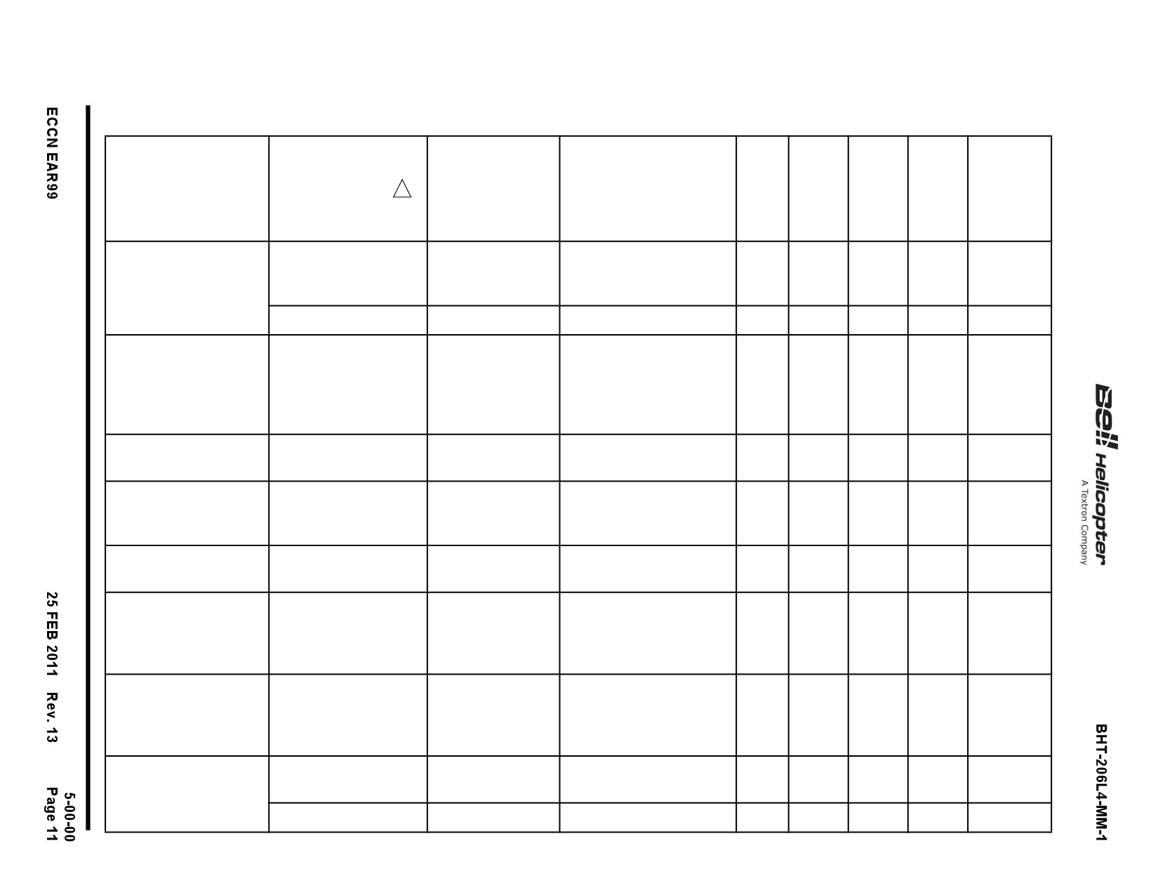
Table 5-3.
300-Hour Airframe Progressive or 300-Hour Airframe Periodic Inspection Program Prerequisites
206L1+
AND
BULLETIN
ACCEPTABLE
NOMENCLATURE
PART NUMBER
2
206L
206L1
206L3
206L4
206L3+
REFERENCE
ALTERNATES
IGW
UPGRADE
Swashplate and
206-010-450-123
TB 206L-00-201
206-010-450-101 is an
X
X
Support Assembly
acceptable alternate to
206-010-450-123.
206-010-450-131
TB 206L-00-201
X
X
X
Main Rotor Hub
206-011-100-105
TB 206L-91-152
206-011-100-159 is an
X
X
X
X
X
Assembly
acceptable alternate
provided ASB
206L-97-108 is
accomplished.
Tail Rotor Hub
206-011-810-153
TB 206L-09-239
X
X
X
X
X
Assembly
Tailboom Attachment
206-031-314-157A
TB 206L-07-226
X
X
X
X
X
Fittings and Longeron
or
or PSE
Assembly
206-031-314-217B
Instructions
Forward Engine Mount
206-031-629-103
BHT-206-SRM
X
X
X
X
X
Fittings
Tailboom Assembly
206-033-004-175/-177
TB 206L-05-220
206-033-004-181, -199,
X
X
X
X
X
or equivalent with ASB
or -203 and
206L-99-115
206-704-727-101.
accomplished
Transmission Restraint
206-033-506-103
206-033-506-107 and
X
X
X
X
X
-109 are acceptable
alternates to
206-033-506-103.
Transmission
206-040-004-107
TB 206L-91-153
X
X
X
Assembly
TB 206L-08-229
206-040-004-115
X
X
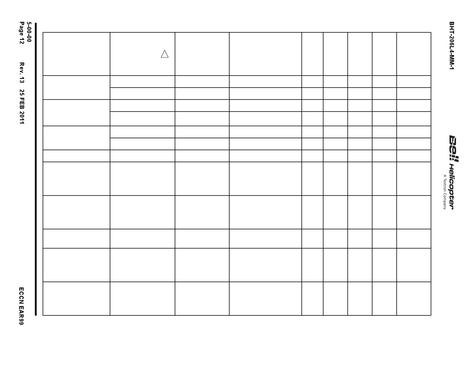
Table 5-3.
300-Hour Airframe Progressive or 300-Hour Airframe Periodic Inspection Program Prerequisites (Cont)
206L1+
AND
BULLETIN
ACCEPTABLE
NOMENCLATURE
PART NUMBER
2
206L
206L1
206L3
206L4
206L3+
REFERENCE
ALTERNATES
IGW
UPGRADE
Mast Assembly
206-040-014-103
TB 206L-99-195
X
X
X
206-040-014-107
TB 206L-99-195
X
X
Main Driveshaft
206-040-015-011
ASB 206L-93-91
X
Assembly
206-040-015-015
ASB 206L-93-91
X
X
(Grease Lubricated)
Freewheel Assembly
206-040-270-117
TB 206L-01-205
X
206-040-270-123
TB 206L-01-205
X
X
Riveted Aft Short Shaft
206-040-383-101
TB 206L-02-207
X
X
Riveted Tail Rotor
206-040-387-101
TB 206L-02-207
206-040-370-107/-109/
X
X
X
X
X
Driveshaft Assembly
-115 are acceptable
fielded substitutes for
206-040-387-101.
Tail Rotor Gearbox
206-040-402-111
TB 206L-99-197
206-040-402-101/-107
X
X
X
X
X
Assembly
are acceptable fielded
substitutes for
206-040-402-111.
Oil Cooler Blower
206-061-432-109
ASB 206L-86-40
X
X
X
X
X
Impeller
Main Driveshaft
206-340-300-105
ASB 206L-01-123
206-340-300-105M is an
X
X
Assembly (KAflex)
TB 206L-01-204
acceptable fielded
substitute for
206-340-300-105.
Freewheel Assembly
406-040-500-113
TB 206L-01-205
X
X
with TB 206L-02-208
and ASB 206L-07-147
accomplished.
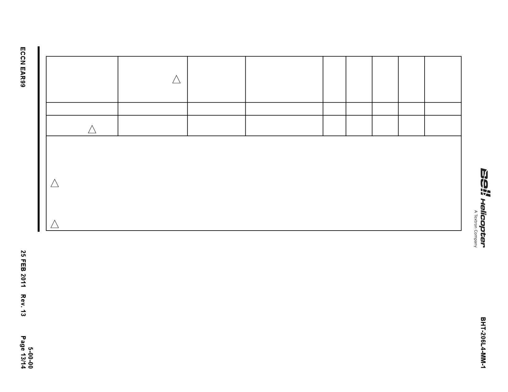
Table 5-3.
300-Hour Airframe Progressive or 300-Hour Airframe Periodic Inspection Program Prerequisites (Cont)
206L1+
AND
BULLETIN
ACCEPTABLE
NOMENCLATURE
PART NUMBER
2
206L
206L1
206L3
206L4
206L3+
REFERENCE
ALTERNATES
IGW
UPGRADE
Aft Fuselage Bulkhead
407-030-027-103
TB 206L-07-226
X
X
X
X
X
FACET Scavenge Oil
Purolator Kit Number
X
X
X
X
X
Filter System
4
STC # SH200GL
NOTES:
1. Table 5-3 is not to be used as a configuration listing for the installation of components on 206L Series Helicopters. It is only provided as a
prerequisite listing to determine applicability to use the 300-hour airframe progressive inspection program or 300-hour airframe periodic
inspection program, as applicable. Refer to the bulletins listed within the table for configuration data as required.
2
To qualify for the 300-hour airframe progressive inspection program or the 300-hour airframe periodic inspection program, the helicopter
must have all of the parts listed installed (or subsequent part numbers to those listed based on configuration/eligibility requirements).
3. If the helicopter does not have all of the parts listed in this table installed, the helicopter is limited to either the 100-hour airframe progressive
inspection or the 100-hour airframe periodic inspection.
4
FACET scavenge oil filter system available from Purolator Facet, Inc., www.purolator-facet.com.
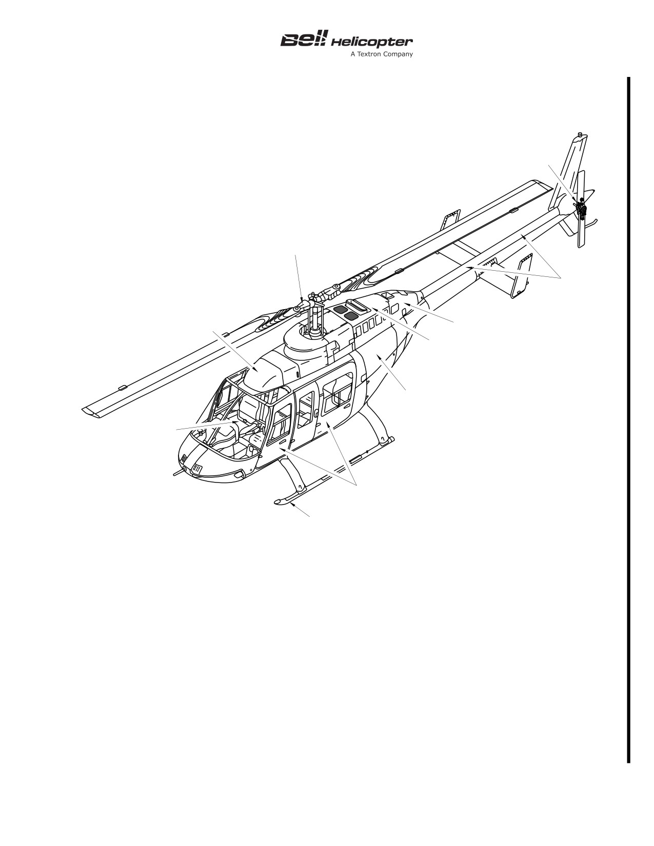
BHT-206L4-MM-1
ZONE 2
ZONE 1
ZONE 6
ZONE 3
ZONE 5
ZONE 4
ZONE 9
ZONE 7
ZONE 8
ZONE 10
Zone 1
- Main rotor hub and blade assembly
Zone 2
- Tail rotor hub and blade assembly
Zone 3
- Forward top deck
Zone 4
- Power plant
Zone 5
- Aft top deck
Zone 6
- Tailboom
Zone 7
- Cabin interior
Zone 8
- Foward fuselage
Zone 9
- Aft fuselage
Zone 10
- Landing gear
206L4_MM_05_0001
Figure 5-1. Maintenance Zones
Page 15/16
BHT-206L4-MM-1
PROGRESSIVE INSPECTIONS
5-16.
100-HOUR AIRFRAME PROGRESSIVE INSPECTION — EVENT NO. 1
INITIAL
DATA REFERENCE
INSPECTION TASK DESCRIPTION
MECH OTHER
DATE: __________________W.O. _____________________
FACILITY: _________________________________________
HELICOPTER S/N: __________________________________
REGISTRY NO.: ____________________________________
TOTAL TIME:_______________________________________
SIGNATURE:_______________________________________
ZONE 1 — MAIN ROTOR SYSTEM
Chapter 11
PLACARDS AND MARKINGS
1.
Examine the placards, decals and markings. Make sure
they are readable, correctly applied and in agreement with the
applicable configuration of your helicopter.
Chapter 62
MAIN ROTOR SYSTEM
1.
Verify main rotor flap restraint for freedom of movement,
and for condition and security.
2.
Examine static stops and mast for evidence of mast
bumping.
3.
Remove main rotor blade leading edge erosion protection
tape, if installed.
4.
Examine main rotor blades for cleanliness and overall
condition. Examine for cracks, corrosion and de-bonding of
doublers.
5.
Examine leading edge of blades for corrosion and erosion.
Restore contour as necessary.
6.
Examine the tip weight cap for corrosion, cracks, erosion,
and deformation.
Page 17
BHT-206L4-MM-1
PROGRESSIVE INSPECTIONS
5-16.
100-HOUR AIRFRAME PROGRESSIVE INSPECTION — EVENT NO. 1 (CONT)
INITIAL
DATA REFERENCE
INSPECTION TASK DESCRIPTION
MECH OTHER
7.
If applicable, reinstall main rotor blade leading edge
erosion protection tape.
8.
Examine the following main rotor hub assembly
components for condition and security:
a. Mast nut
b. Trunnion
c. Pillow blocks
d. Grips
e. Pitch horns
f. Static stops
9.
Examine pitch horn trunnion bearings for evidence of wear,
damage, and for security.
10. Torque check pillow block retention hardware
84 to
107 inch-pounds (9.4 to 12 Nm). Examine for misalignment of
anti-slippage marks.
11. Examine main rotor yoke for corrosion or mechanical
damage as follows:
BHT-206L-CR&O
a. Examine fillet radius of both yoke spindles inboard of
wear sleeves for evidence of corrosion. If corrosion is visible,
remove with fine abrasive pad (C-407). If corrosion cannot be
removed with pads, or is extensive, disassemble hub for
inspection and repair.
NOTE
If the main rotor hub must be disassembled, omit
remaining steps.
b. Examine entire yoke centre section
(inboard and
outboard surfaces) for damage.
Page 18
Rev. 20
7 NOV 2014
Export Classification C,
BHT-206L4-MM-1
PROGRESSIVE INSPECTIONS
5-16.
100-HOUR AIRFRAME PROGRESSIVE INSPECTION — EVENT NO. 1 (CONT)
INITIAL
DATA REFERENCE
INSPECTION TASK DESCRIPTION
MECH OTHER
c. Touch up all repaired areas or areas of bare metal in
accordance with applicable main rotor hub inspection and repair
instructions.
d. Ensure no sealant voids are visible around shields or
wear sleeve, strap fittings, and grip closure. Recoat with sealant
(C-308) as required. On main rotor hub assemblies up to and
including P/N 206-011-100-025, coat the remaining exposed
fillet radius and repaired surfaces with a film of corrosion
preventive compound (C-101).
ZONE 2 — TAIL ROTOR ASSEMBLY
Chapter 11
PLACARDS AND MARKINGS
1.
Examine the placards, decals and markings. Make sure
they are readable, correctly applied and in agreement with the
applicable configuration of your helicopter.
Chapter 64
TAIL ROTOR ASSEMBLY
1.
Clean tail rotor blades to maintain visibility of warning
stripes.
BHT-206L-CR&O
2.
Examine the following tail rotor hub assembly components
for condition and security of attachment:
a. Yoke
b. Pitch horns
c. Trunnion and trunnion caps
d. Counterweight hardware
Chapter 64
3.
Examine tail rotor blades as follows:
a. Tip block rivets for damage, corrosion, erosion, and
looseness.
b. Skin for bulges, nicks, dents, scratches, or other
damage.
Page 19
BHT-206L4-MM-1
PROGRESSIVE INSPECTIONS
5-16.
100-HOUR AIRFRAME PROGRESSIVE INSPECTION — EVENT NO. 1 (CONT)
INITIAL
DATA REFERENCE
INSPECTION TASK DESCRIPTION
MECH OTHER
c. Deformed or cracked skin in the area of the chordwise
weights.
d. Leading edge for erosion, nicks, dents or scratches.
e. Bonded joints of blade skin mating area for suspected
voids or cracks. Pay particular attention in the area of tip block
and doublers.
f. Feathering bearings for looseness and cracks in uniball.
4.
Examine the following tail rotor hub and blade assembly
attaching components for condition and security:
a. Spacer
b. Rubber bumper
c. Static stop
d. Nut
e. Balance wheel
ZONE 3 — FORWARD DECK
Chapter 11
PLACARDS AND MARKINGS
1.
Examine the placards, decals and markings. Make sure
they are readable, correctly applied and in agreement with the
applicable configuration of your helicopter.
AIRFRAME (FORWARD DECK)
Chapter 71
1.
Open and examine forward fairing for condition and
security.
2.
Remove and examine transmission cowling for condition.
3.
Examine all fairing and cowling latches and/or fasteners for
condition
4.
Examine top deck for condition, leaks and security.
Page 20
BHT-206L4-MM-1
PROGRESSIVE INSPECTIONS
5-16.
100-HOUR AIRFRAME PROGRESSIVE INSPECTION — EVENT NO. 1 (CONT)
INITIAL
DATA REFERENCE
INSPECTION TASK DESCRIPTION
MECH OTHER
Chapter 53
5.
Clean transmission deck.
6.
Examine air induction cowling and plenum for damage,
obstructions and cleanliness. Examine intake fairing windows
for damage and cleanliness.
7.
Examine inlet screen (if applicable) for missing or damaged
wires and rivets.
8.
Examine particle separator
(if applicable) vortex tubes,
ejector tubes, and ejector nozzles for cleanliness, condition, and
security.
9.
Examine forward deck drain(s) to ensure absence of
obstruction.
10. Examine antennas for condition and security.
Chapter 67
CONTROLS
1.
Examine the following flight control components for signs
of interference, corrosion, wear, mechanical damage and
security:
a. Control tubes.
b. Links.
c. Rod and bearings.
d. Bellcranks.
e. Bellcrank supports.
f. Attaching bolts and nuts.
2.
Inspect main rotor pitch links with a 3X magnifying glass for
damage, corrosion and cracks. Give particular attention to
swaged ends at jam nut or inserts.
Chapter 76
3.
Examine N2 control linkages on forward deck for condition
and security. Pay particular attention to the jackshaft assembly
for damage or evidence or twisting.
Page 21
BHT-206L4-MM-1
PROGRESSIVE INSPECTIONS
5-16.
100-HOUR AIRFRAME PROGRESSIVE INSPECTION — EVENT NO. 1 (CONT)
INITIAL
DATA REFERENCE
INSPECTION TASK DESCRIPTION
MECH OTHER
4.
Verify all control tubes and bellcranks for freedom of travel
throughout range.
Chapter 62
SWASHPLATE ASSEMBLY AND MAST
1.
Clean swashplate assembly and mast.
2.
Disconnect main rotor pitch links from outer ring.
3.
Disconnect idler (drive) link from outer ring.
4.
Examine swashplate drive assembly for axial, radial, and
accumulative wear.
5.
Disconnect boot from swashplate outer ring and lift up
temporarily. Examine boot for evidence of deterioration.
6.
Verify condition of duplex bearing, before lubrication, as
follows:
a. Rotate outer ring to check duplex bearing for condition.
Bearing must be smooth and show no evidence of roughness,
binding, dragging, or looseness.
7.
Examine pivot sleeve slot sidewalls for wear or
deterioration.
8.
Examine pivot sleeve bearings for wear, deterioration and
evidence of excessive axial play between pivot sleeve and
swashplate support.
9.
Examine collar set bushings for cracks and damage.
10. Examine swashplate support and uniball surfaces for
condition.
11. Examine collective lever to sleeve assembly pins for
condition.
12. Examine inner ring for condition. Examine for evidence of
contact with sleeve assembly.
13. Examine outer ring for condition.
Page 22
BHT-206L4-MM-1
PROGRESSIVE INSPECTIONS
5-16.
100-HOUR AIRFRAME PROGRESSIVE INSPECTION — EVENT NO. 1 (CONT)
INITIAL
DATA REFERENCE
INSPECTION TASK DESCRIPTION
MECH OTHER
14. Examine the upper inside diameter of swashplate support
for evidence of contact with the mast pole.
15. Connect and secure boot, idler (drive) link and main rotor
pitch links to outer ring.
16. Examine swashplate assembly for condition and security.
Chapter 63
17. Examine mast for condition.
Chapter 62
18. Ensure no sealant voids are visible around the swashplate
drive collar set. Re-coat with adhesive (C-307) as required.
Chapter 29
HYDRAULIC SYSTEM
1.
Examine rigid and flexible fluid lines for chafing, leaks and
security.
2.
Examine hydraulic pump for leaks and general condition.
3.
Examine hydraulic reservoir for leaks and general
condition.
4.
Examine servo actuators for leaks, condition and security.
5.
Examine servo actuator support for condition.
Chapter 67
6.
Verify linkage pivot bolts on hydraulic servo actuators for
freedom of rotation and security.
7.
Examine hydraulic filter red indicator button (two locations).
Button should not be extended.
Chapter 12
8.
Verify fluid level in hydraulic tank. Replenish as required.
Replace fluid if color has changed color or if fluid emits bad
odor.
9.
Examine manifold, relief valve, and solenoid valve for
leaks, condition and security.
Chapter 63
TRANSMISSION AND PYLON ASSEMBLY
1.
Examine the following pylon support components:
Page 23
BHT-206L4-MM-1
PROGRESSIVE INSPECTIONS
5-16.
100-HOUR AIRFRAME PROGRESSIVE INSPECTION — EVENT NO. 1 (CONT)
INITIAL
DATA REFERENCE
INSPECTION TASK DESCRIPTION
MECH OTHER
a. Transmission link assemblies and bearings for damage
and deterioration.
b. Nodal beam flexures for condition and security.
c. Forward and aft nodal beam deck supports for condition
and security. Check torque on heads of bolts only (bolts must
not rotate). If a bolt is loose, remove nut. Install new nut and
torque 75 to 95 inch-pounds (8.4 to 10.7 Nm).
d. Nodal beam stops for evidence of excessive contact
with nodal beam arms.
e. Transmission restraint for damage and spherical
bearings for excessive wear and security.
f. Stop mount for condition and security. Stop mount
bushings for wear.
g. All pylon support elastomeric components for evidence
of deterioration.
h. All pylon support hardware for security of attachment.
2.
Examine transmission assembly for condition and security.
3.
Examine transmission assembly for evidence of oil
leakage.
4.
Examine all fluid lines for chafing, damage and evidence of
leakage.
5.
Examine transmission oil for evidence of contamination.
6.
Examine transmission oil filter bypass indicator for
condition. Bypass button should not be extended.
7.
Inspect all transmission chip detectors for accumulated
material.
8.
Perform functional test of all transmission chip detectors.
Page 24
Rev. 18
7 JUN 2013
Export Classification C,
BHT-206L4-MM-1
PROGRESSIVE INSPECTIONS
5-16.
100-HOUR AIRFRAME PROGRESSIVE INSPECTION — EVENT NO. 1 (CONT)
INITIAL
DATA REFERENCE
INSPECTION TASK DESCRIPTION
MECH OTHER
9.
Ensure no sealant voids are visible around forward and aft
nodal beam deck mounted supports and isolation mount.
Recoat with sealant (C-308) as required.
MAIN DRIVESHAFT
Chapter 63
1.
Examine the engine to transmission driveshaft for condition
and security. Examine the components as follows:
a. Driveshaft for cracks, corrosion, and surface damage.
b. Flexframe and bolts for condition and signs of slippage.
Chapter 96
ELECTRICAL
1.
Examine all electrical components, wires, cables and
connectors in the area of the forward deck and transmission for
chafing, general condition, and security.
GROUND RUN
CAUTION
GROUND RUN OF HELICOPTER TO BE
ACCOMPLISHED BY QUALIFIED PERSONNEL
ONLY.
Chapter 12
1.
Make sure applicable servicing requirements have been
carried out.
2.
Check oil level of transmission, hydraulic tank, engine and
rail rotor gearbox prior to running helicopter.
3.
Make sure that helicopter is ready for ground run and that
surrounding area is clear.
BHT-206L4-FM-1
4.
Start the helicopter and conduct ground run at 100% NR to
check for leaks and ensure all systems are operational and
parameters are within Flight Manual limitations.
7 JUN 2013
Rev. 18
Page 25/26
Export Classification C,
BHT-206L4-MM-1
PROGRESSIVE INSPECTIONS
5-17.
100-HOUR AIRFRAME PROGRESSIVE INSPECTION — EVENT NO. 2
INITIAL
DATA REFERENCE
INSPECTION TASK DESCRIPTION
MECH OTHER
DATE: __________________W.O. _____________________
FACILITY: _________________________________________
HELICOPTER S/N: __________________________________
REGISTRY NO.: ____________________________________
TOTAL TIME:_______________________________________
SIGNATURE:_______________________________________
ZONE 4 — POWER PLANT
Chapter 11
PLACARDS AND MARKINGS
1.
Examine the placards, decals and markings. Ensure they
are readable, correctly applied and in agreement with the
applicable configuration of your helicopter.
AIRFRAME (POWER PLANT AREA)
Chapter 71
1.
Examine firewalls for condition and security.
2.
Examine engine pan area for evidence of loose fasteners
and damage. Restore cracked or missing sealant form engine
pan.
3.
Examine engine pan drains. Make sure that they are not
clogged.
Chapter 28
4.
Examine airframe fuel filter assembly for evidence of
leakage and security.
Chapter 71
5.
Examine engine mount legs for condition and security. Pay
particular attention for loose fasteners.
6.
Examine engine mount fittings for condition and security.
Applicable Service
7.
Examine rotor brake (if installed) for condition and security.
Instruction
Page 27
BHT-206L4-MM-1
PROGRESSIVE INSPECTIONS
5-17.
100-HOUR AIRFRAME PROGRESSIVE INSPECTION — EVENT NO. 2 (CONT)
INITIAL
DATA REFERENCE
INSPECTION TASK DESCRIPTION
MECH OTHER
Chapter 96
8.
Examine the primary electrical ground connection in
engine pan area for condition and security
POWER PLANT
Rolls-Royce 250-C30
1.
Perform engine inspection per the applicable Rolls-Royce
Series Operation and
Operation and Maintenance Manual.
Maintenance Manual,
14W2
Chapter 71
2.
Examine engine inlet bellmouth for obstruction and general
condition.
3.
Examine engine compartment hardware for security of
attachment.
4.
Examine engine for evidence of fuel or oil leaks.
5.
Examine all flexible and rigid lines for condition and
security.
a. Pay particular attention for chafing damage and kinked
lines.
6.
Examine exhaust stack for condition and security.
7.
Examine all engine-mounted accessories for condition and
security.
Chapter 75
8.
Examine the engine anti-ice solenoid valve for condition
and security.
Chapter 76
9.
Inspect fuel control lever bolt hole and bolt for wear.
Replace parts as required.
10. Deleted
11. Deleted.
Chapter 76
12. Examine engine controls for condition and security.
13. Verify operation of engine N1 control as follows:
a. Ensure proper throttle friction.
Page 28
18 JUL 2019
Export Classification C,
BHT-206L4-MM-1
PROGRESSIVE INSPECTIONS
5-17.
100-HOUR AIRFRAME PROGRESSIVE INSPECTION — EVENT NO. 2 (CONT)
INITIAL
DATA REFERENCE
INSPECTION TASK DESCRIPTION
MECH OTHER
b. Check freedom of full throttle grip travel and idle release
operation. Return to closed position. Check copilot throttle if
installed.
c. Ensure fuel control stop lever contact with minimum and
maximum stops before throttle grip reaches travel limit.
NOTE
If dual controls are installed, it is permissible for
pointer to be 0.078 inch (1.98 mm) below 40° mark
when copilot twist grip is used.
d. Rotate throttle grip to idle detent, fuel control pointer
should be no more than 0.01 inch (0.25 mm) below the 40°
mark on the quadrant.
e. Verify control linkage for excessive looseness, lost
motion, and binding.
14. Verify operation of engine N2 control as follows:
a. Position N2 governor actuator to full DECREASE
(extended).
b. Lift collective stick full up.
c. Position N2 governor actuator to full INCREASE
(retracted).
d. Verify for clearance between governor stop and lever
stop arm.
e. Lower collective stick full down.
f. Position N2 governor actuator to full DECREASE
(extended).
g. Verify for clearance between governor stop and lever
stop arm.
Chapter 71
h. Verify control linkage for excessive looseness, lost
motion, and binding.
Page 29
///////////////////////////////////////