Computerized Embroidery Machine Controller BECS-A15. OWNER’S MANUAL - page 3
Chapter
8 Assistant Operation
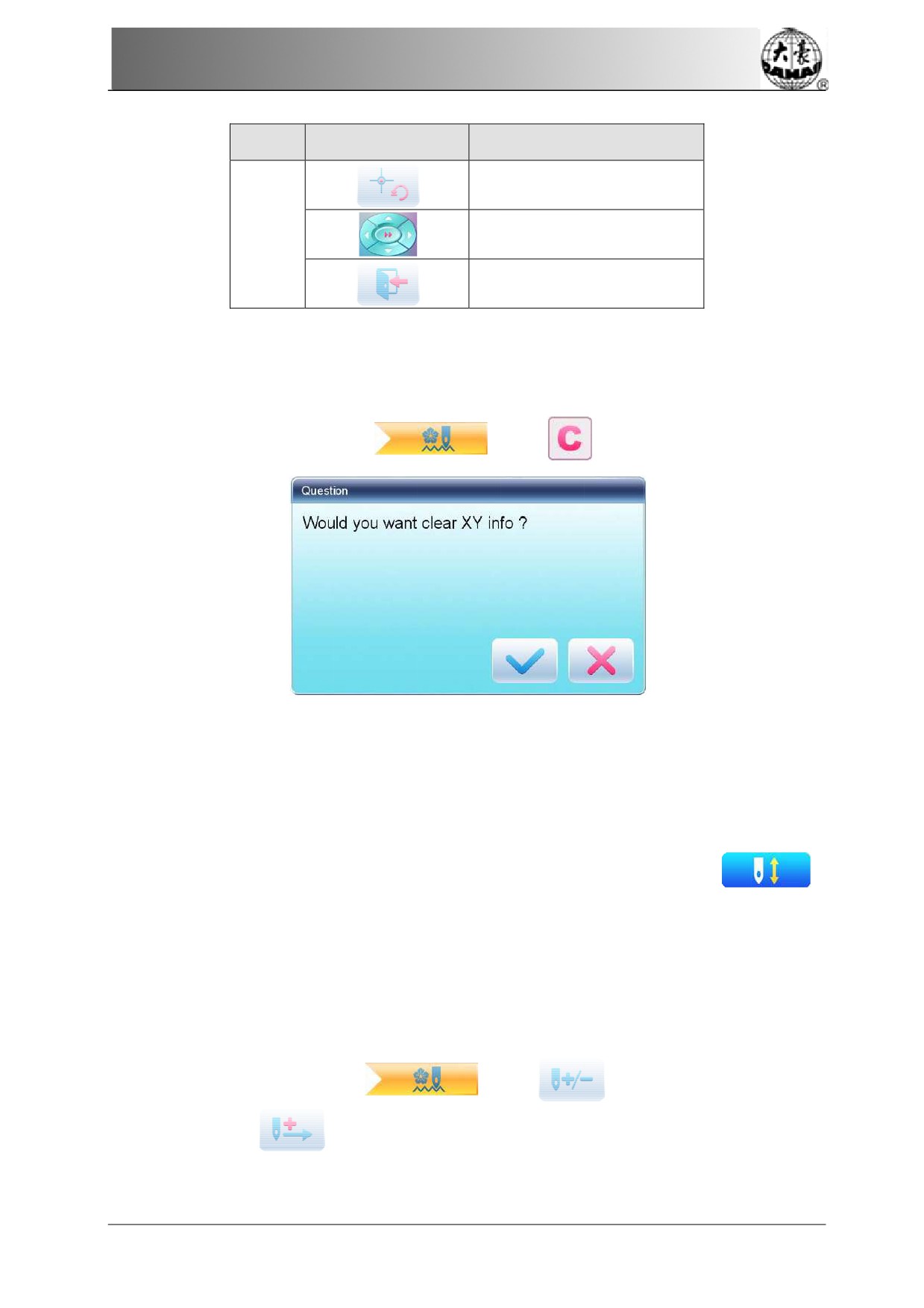
No.
Icon
Name
Recovery of Pattern Origin
2
Manual Pattern Movement
Exit
8.2 Clear XY Displacement
This function
is to clear the X and Y
displacements.
1.
In the
main interface
, press
2
System
will set current X/Y
value to 0.
User can check the current X/Y value on the main interface
8.3 Positioning
Idling
This operation
can only be undertaken under embroidery confirmation
status
This function
can move
the frame to certain position without embroidering according to
user’s need. User can select color-changing code or
stop code
as reference to idle forward (or
backward).
8.3.1. Low
Speed
Idling Forward
1. In the
main interface
, press
2. Press
63
Chapter
8
Assistant Operation
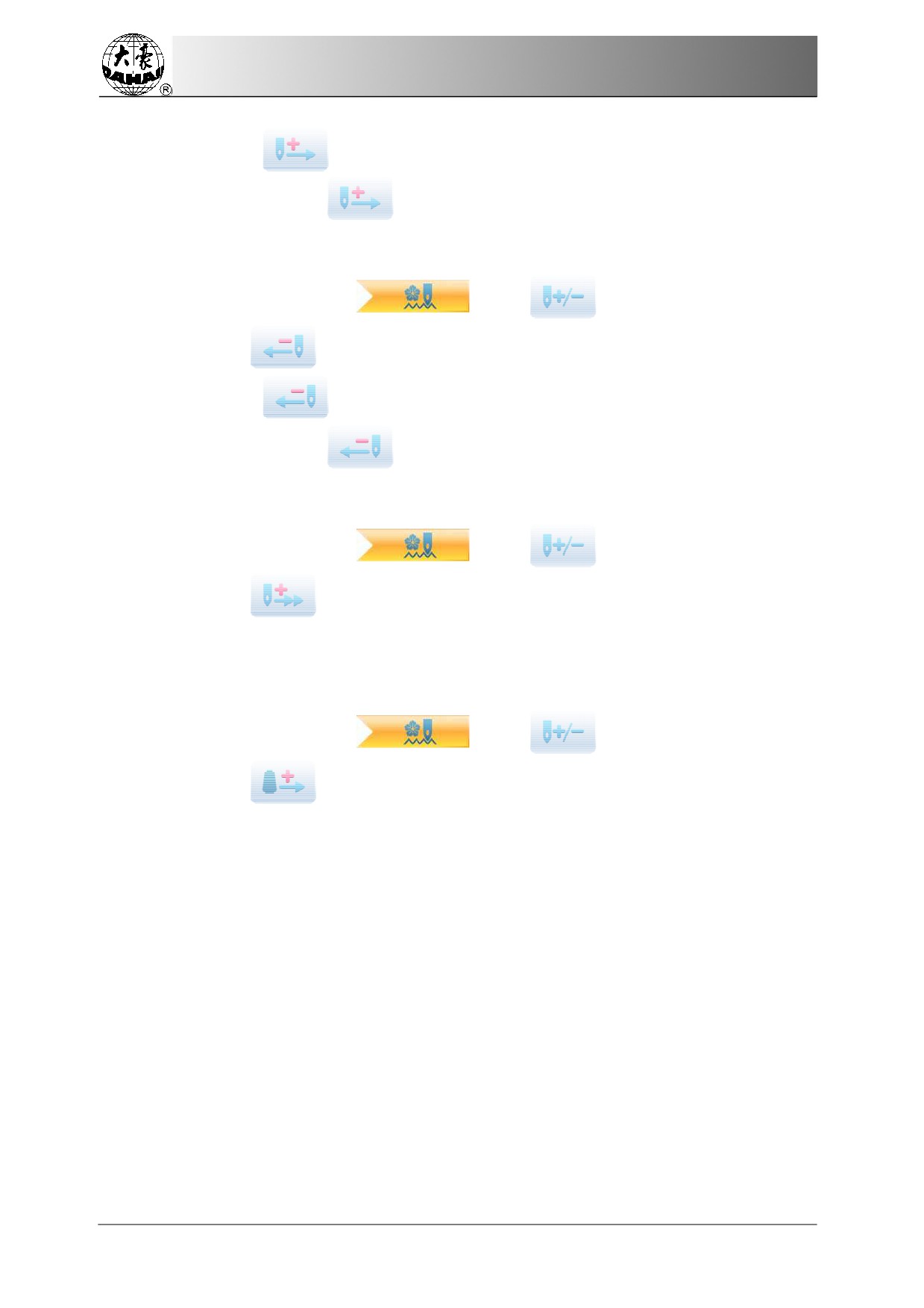
(1) Press
once to idle
forward by one stitch
(2) Hold
pressing
for 2s to idle
forward continuously
8.3.2. Low
Speed
Idling Backward
1. In the main interface
, press
2. Press
(1) Press
once to idle
backward
by one stitch
(2) Hold
pressing
for 2s to idle
backward continuously
8.3.3. Hig
h Speed
Idling Forward
1. In the main interface
, press
2. Press
to
idle forward at high speed
Note: the operation method of high speed idling backward is the same with here.
8.3.4. Go
to Next
Color
1. In the main interface
, press
2. Press
to
idle to the
next color-changing code
Note: the operation method of “go
to previous color” is
the same with here.
64
Chapter 9 Other Functions
Chapter 9 O
ther Functions
These functions can be used during the
usage, including machine maintenance,
information inquiry
and system
settings.
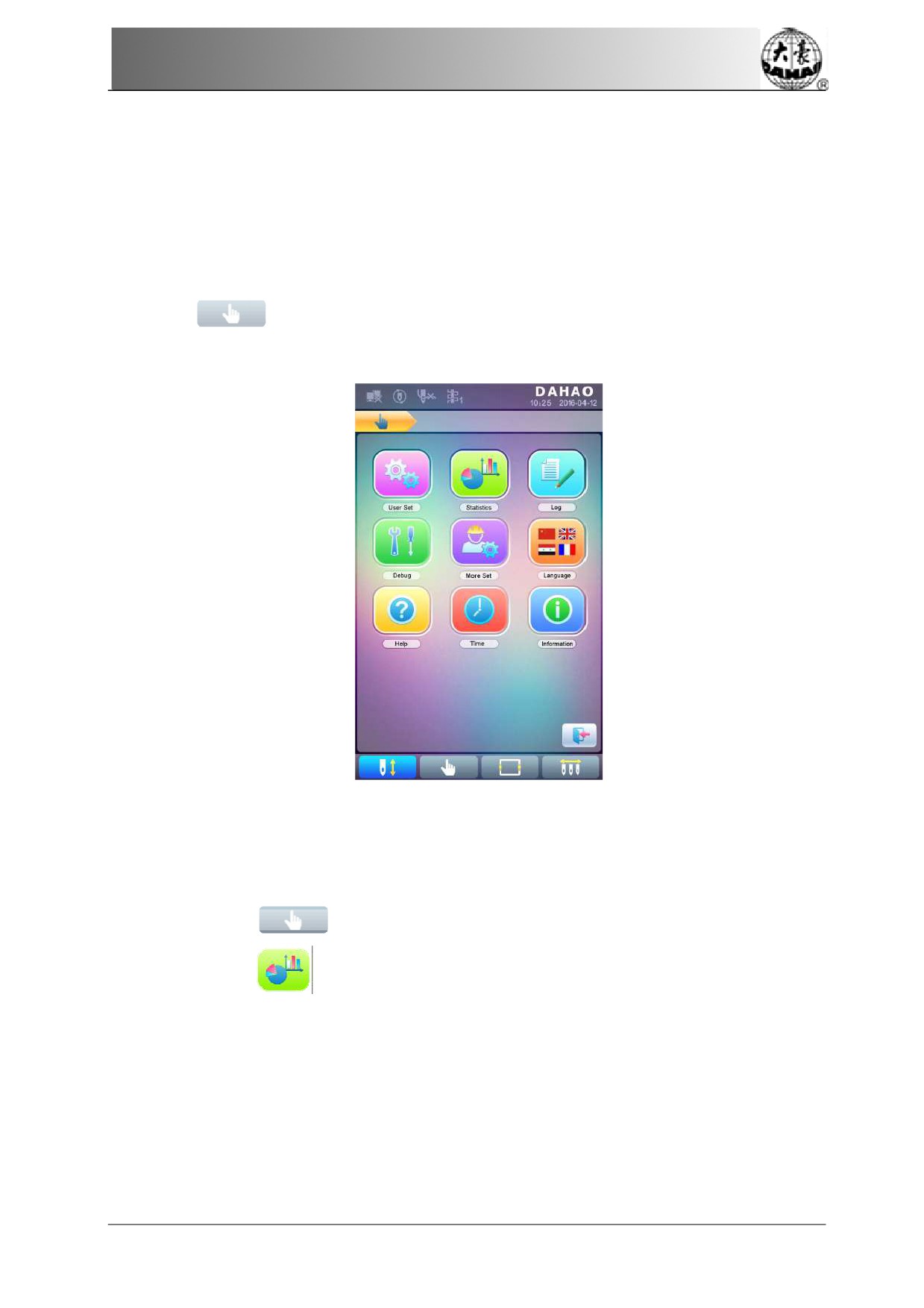
Press
to enter
the interface for other
function, where a list
of function
keys will
be displayed for user to operate by pressing.
The words on
the keys can help user
understand
the functions.
9.1 Statistics
1.
Press
to enter the
interface for other functions.
2
Press
to
enter the interface of statistics.
65
Chapter 9 Other Functions
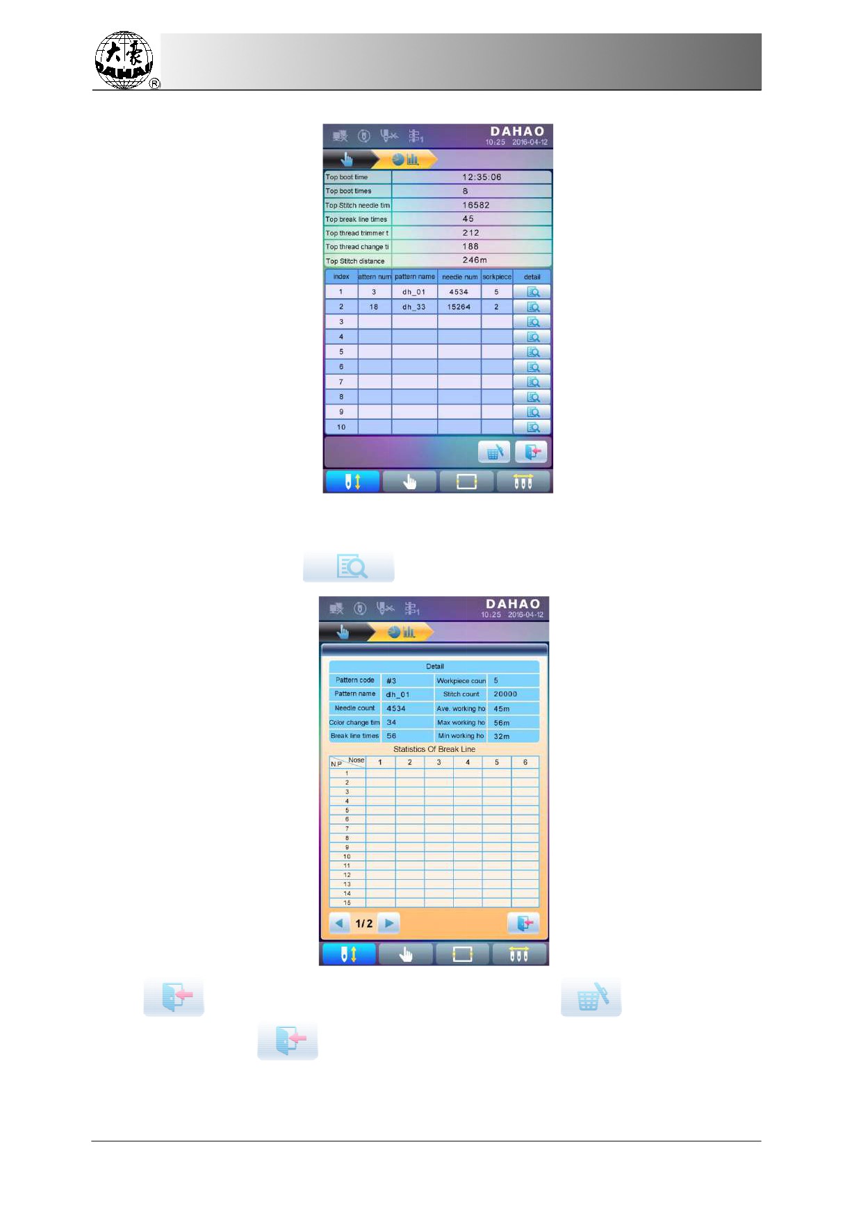
In the above interface, the statistic information is displayed in
a chart.
If user need check
details of
each pattern, press
to enter the corresponding interface.
Press
to
return to
the interface of statistics. Press
to delete
statistic
information and press
to return.
66
Chapter 9 Other Functions
9.2 Set Frame
Origin
Setting the frame origin is the premise for saving the pattern’s start point and setting frame
protection at sudden power-off. So after the installation or
maintenance of machine, it’s
necessary to set the
frame origin.
1.
Press
to enter the
interface for other functions.
2
Press
to
enter debugging interface.
3
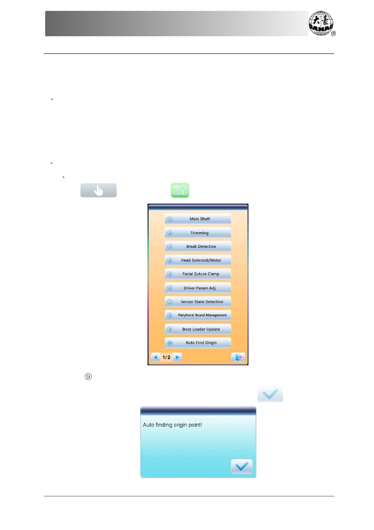
Select
“Auto Find
Origin Point”
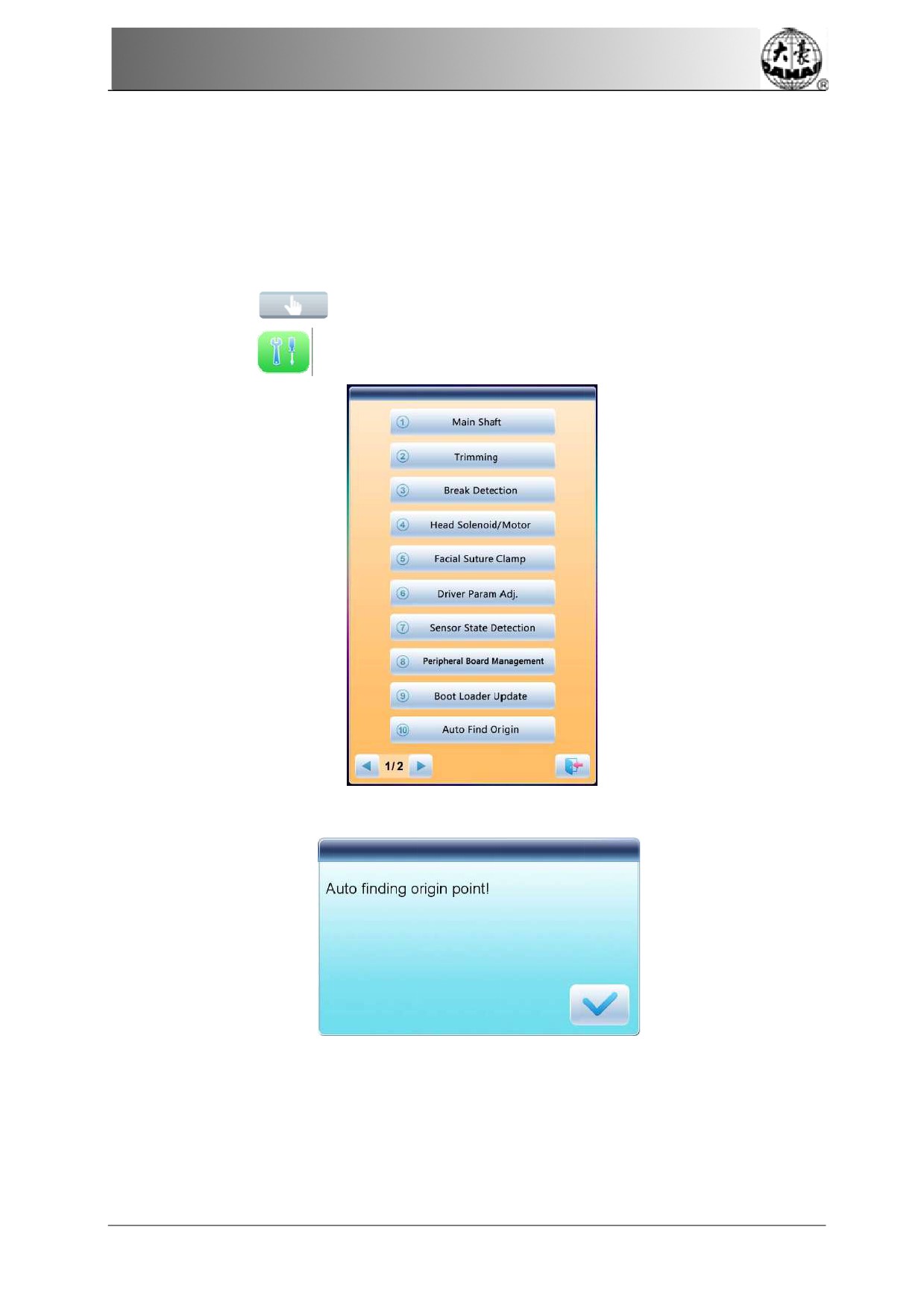
System will move the frame automatically and
determine the origin according to
the limit
switch. So please ensure that the limit switch has been installed into the machine and
activated.
67
Chapter 9 Other Functions
9.3 Language
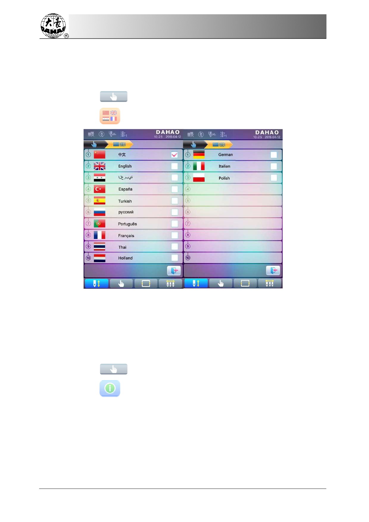
System supports Chinese,
English, Turkish, Spanish, and so
on.
1
Press
to enter the
interface for other functions.
2.
Press
to enter language interface.
Select the language you want and system will
enter the main interface in the selected
language
9.4 Machine Information
Operation Procedures:
1.
Press
to enter the
interface for other functions.
2.
Press
68
Chapter 9 Other Functions
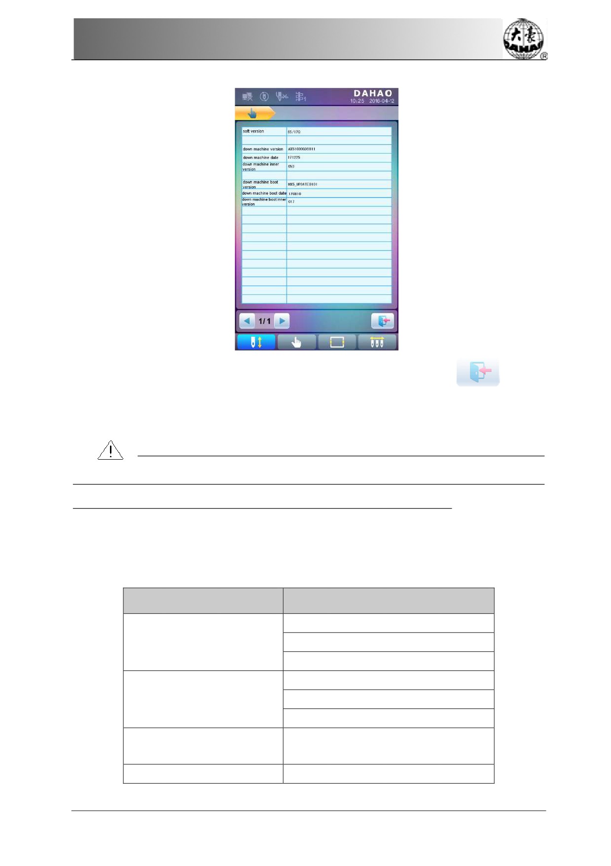
This function
will help user check machine software information. Press
to quit.
9.5 Machine Debugging
This operation is only for
repairman,
ordinary users are banned to undertake
these operations.
Because these operations involve some
mechanical
work, please pay
attention to the personal safety
and equipment security during the operation.
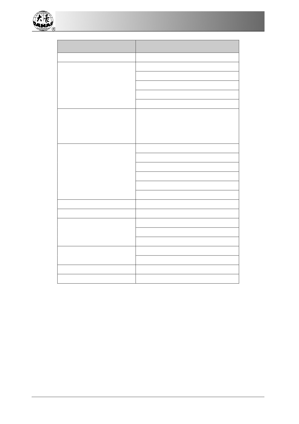
Debugging function is to
mainly used for testing, maintenance and fault inspection of the
machine, which include the
following
function
(debugging
items will
be differentfor the
different models):
Debugging Interface 1
Debugging
Interface 2
Main Shaft Speed And Encoder
Test
Main Shaft
Main Shaft to Any Angle
Main Shaft Angle
Trimming solenoid/Motor
Trimming
Hold solenoid/Motor
Hook Solenoid/Motor
Change
needle position, needle bar
Breakage Detection
color and
adjust main shaft manually
Head Solenoid/Motor
Up, down, combined test
69
Chapter 9 Other Functions
Debugging Interface 1
Debugging Interface 2
Facial Suture Clamp
X-axis parameter test
Y-axis parameter test
Driver Parameter Test
Main shaft parameter test
Save driver parameters
Load driver parameters
Test pull bar switch, frame limit, knife
origin,
knife
maximum point,
Sensor Status Test
thread-hooking origin, and needle
position display, etc.
Peripheral board upgrade
All Peripheral Board Write Address
Peripheral board
Single Peripheral Board Write Address
Management
All Peripheral Board Address Check
Single Perpheral Board Address Check
Perpheral Board Informa on
Boot Loader Upgrade
Auto Find Origin
External CAN communication test
Other
External communication test
Touch screen correction
Import machine parameters
Param Export/Import
Export machine parameters
Param Init
Clear All Pa erns
9.6
Date and Time
In date and time interface, user can check and modify the date and time of the system.
9.7
Touch Screen Correction
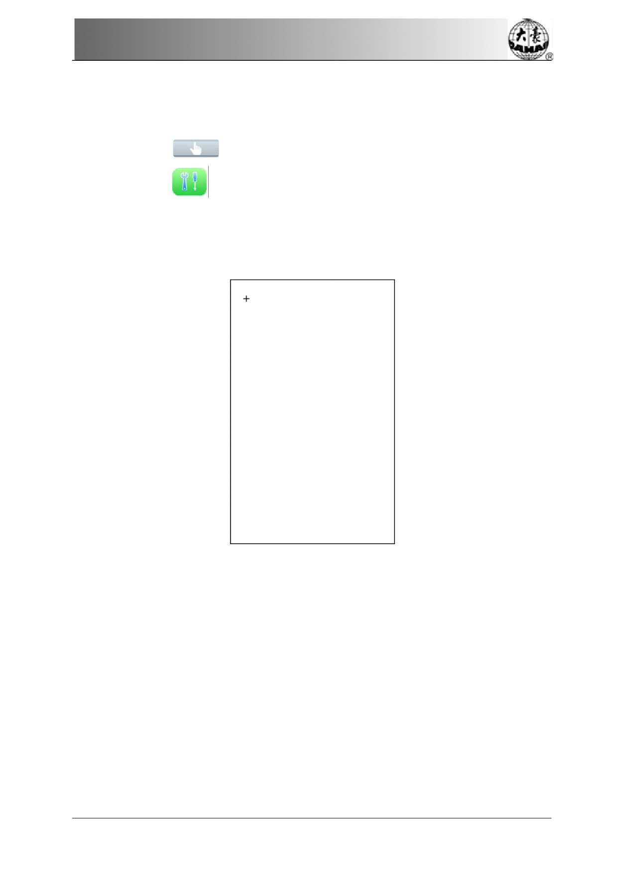
After using for a period, the touch screen may probably have the problem of the inaccurate
operation. This problem can be resolved by touch screen correction. During the correction,
please touch the very center of the cross displayed on the screen, or it may affect the future
70
Chapter 9 Other Functions
operation. In order
to avoid the trouble
caused by the inaccurate correction, this operation is
only for
the person
with authorization.
1.
Press
to enter the
interface for other functions.
2
Press
to
enter debugging interface, where
user can select “Other” to enter
the corresponding interface.
3
Press
“touch screen correction” to enter
the correction interface.
4
Press
the center of the crosses one by one.
During the process of correction, a
lot of crosses will appear on the
screen. User should
press the center of
them. System receives the data of those points and saves them as
standard
data for
correction.
5
System
will make correction according to the coordinates of points pressed by
users.
System will make the correction and then return to the interface
for other
functions
automatically.
71
Chapter 10 Online Update of
Main Software
Chapter
10 O
nline Update of Main
Software
Update Procedure
1. Hold pressing
and power
on.
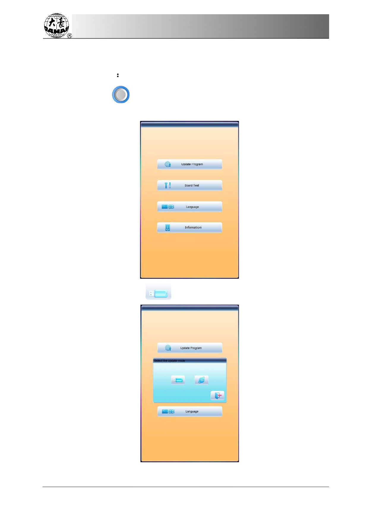
2. The screen
will display the following interface, where user should select
“update
program”
3. Select the update method
(via U disk)
72
Chapter 10
Online Update of Main Software
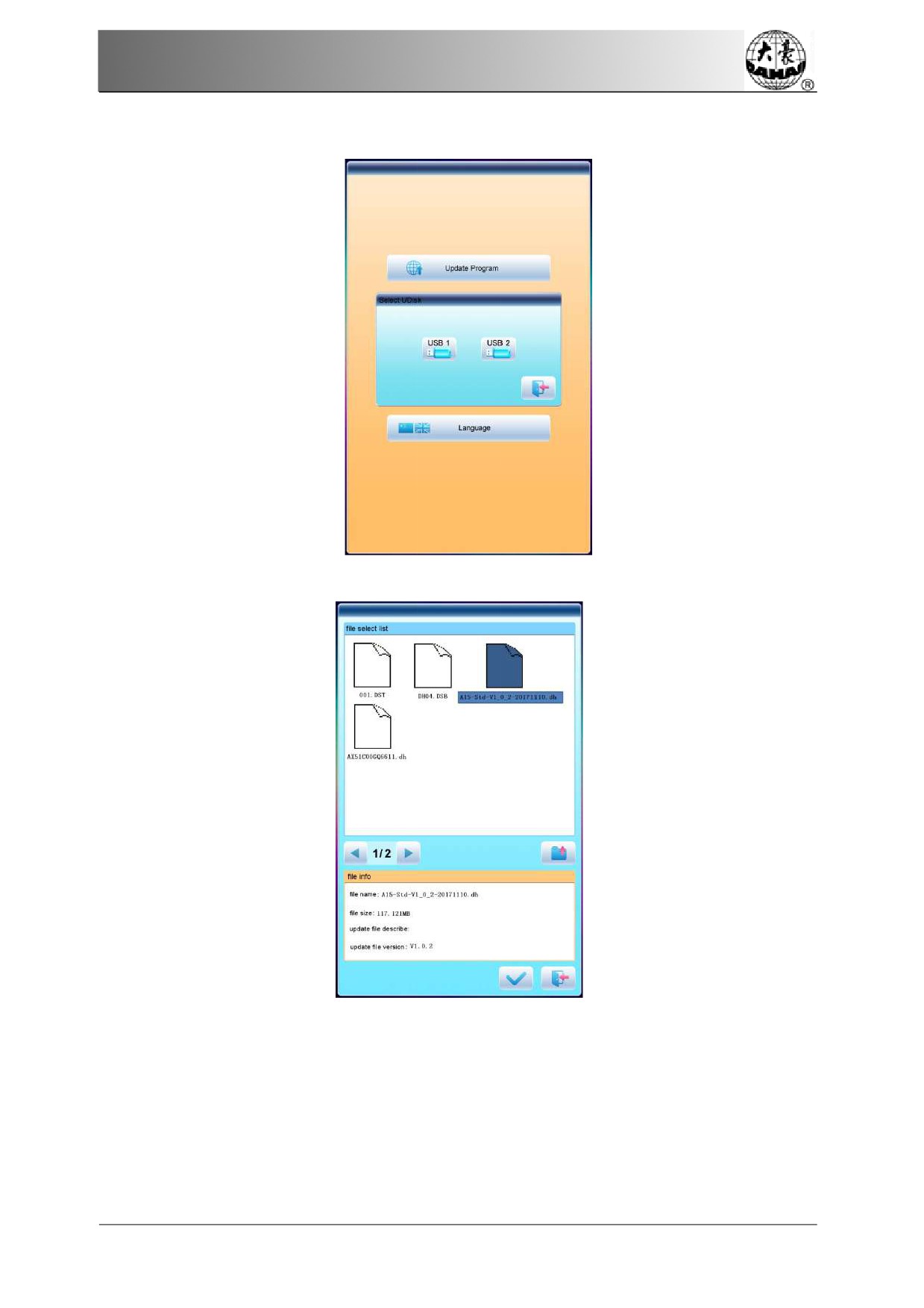
4. System will display the
window to
“Select U Disk”, and select the target U disk
5. After entering the interface of the U
disk, select the program to be updated.
73
Chapter 10 Online Update of
Main Software
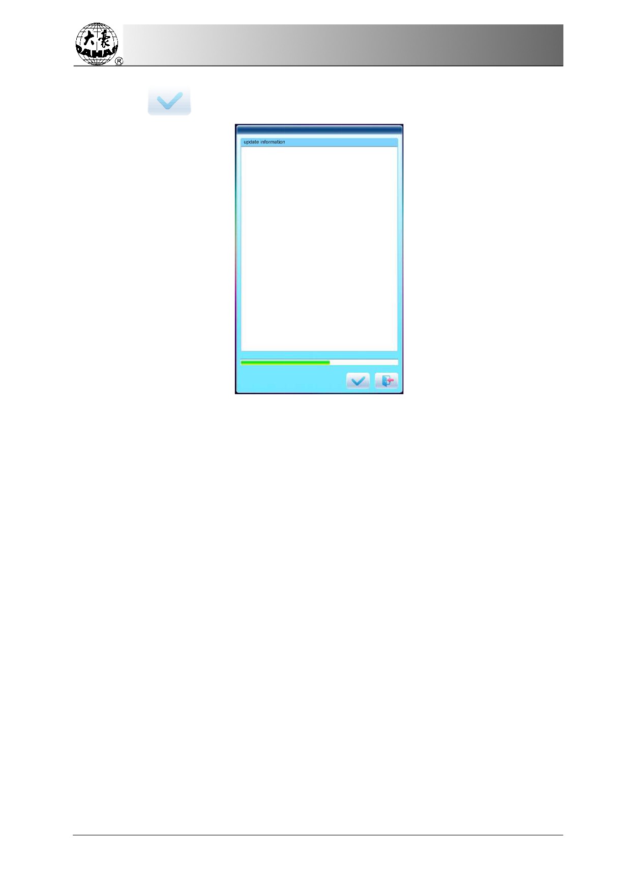
6. Press
to update.
7. When finishing update, system will automatically display a hint “update completed, if
no others, please restart”, and then
please restart.
74
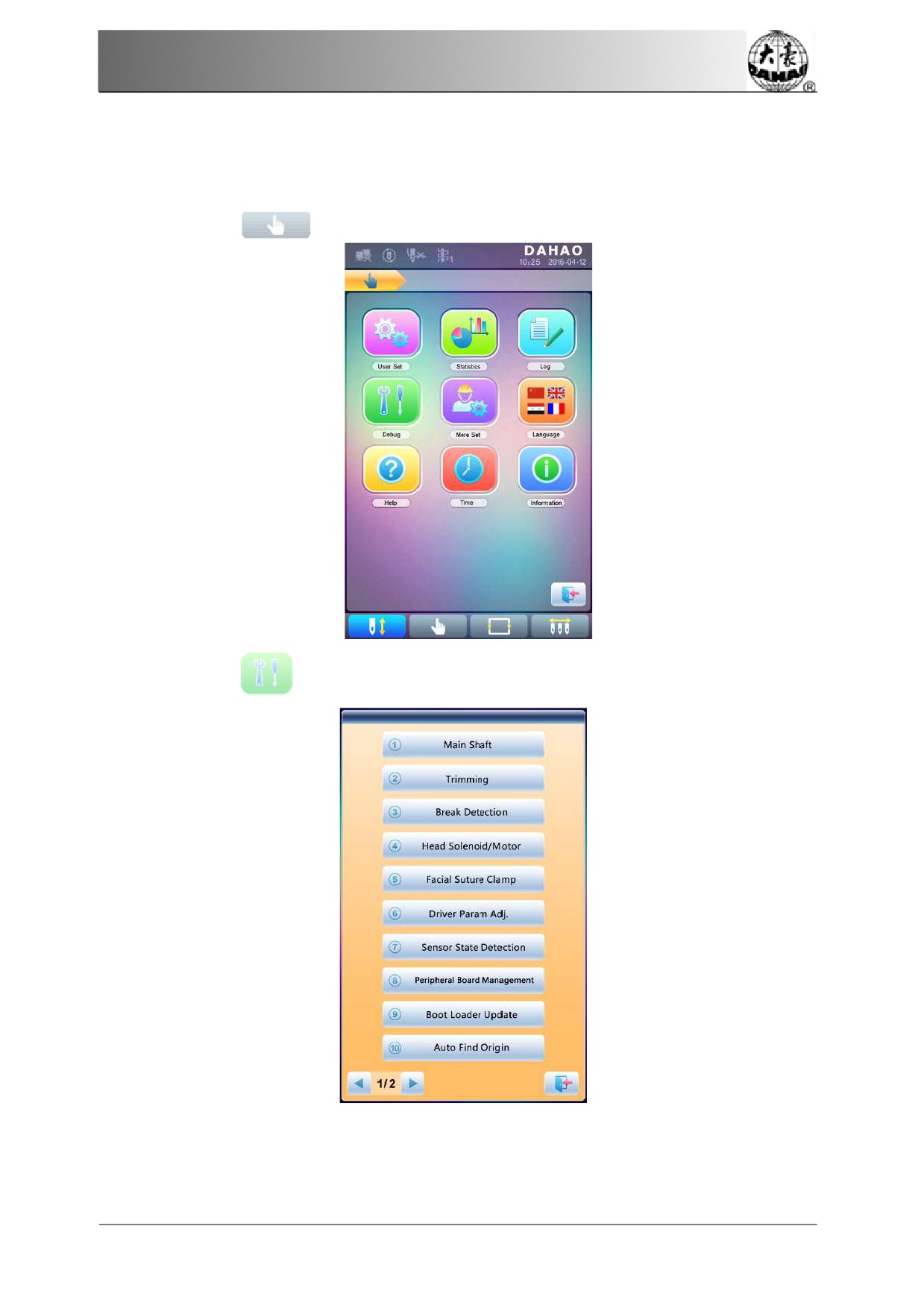
Chapter 11
Update
of Software in
Peripheral Board
Chapter 11
Update
of Software in
Peripheral Board
Update
Procedure:
1.
Press
to
enter the interface for
other functions.
2.
Press
to enter the interface of statistics.
75
Chapter 11
Update of Software in
Peripheral Board
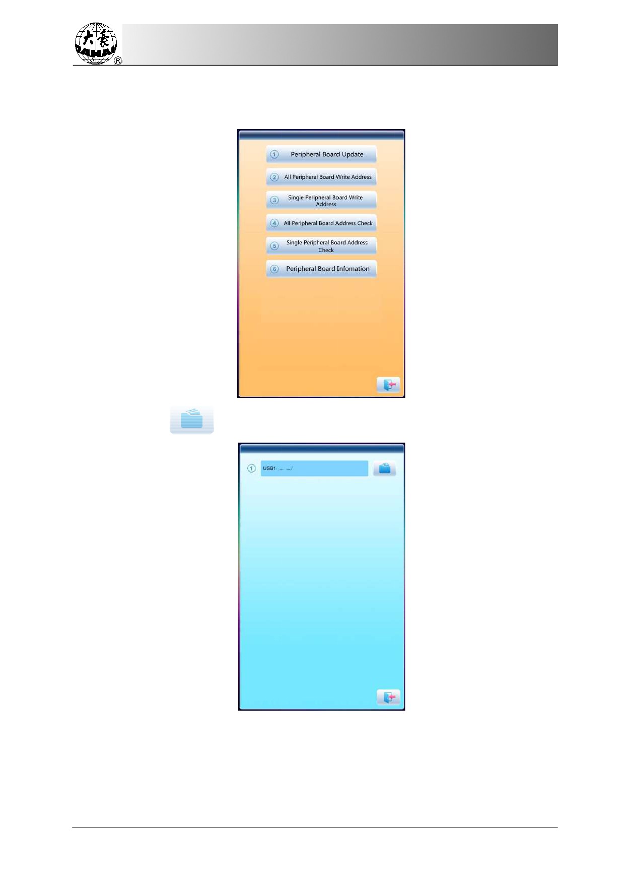
3.
Select
“peripheral
board management”
to enter the
management interface, where
user should select
“peripheral
board update”.
4.
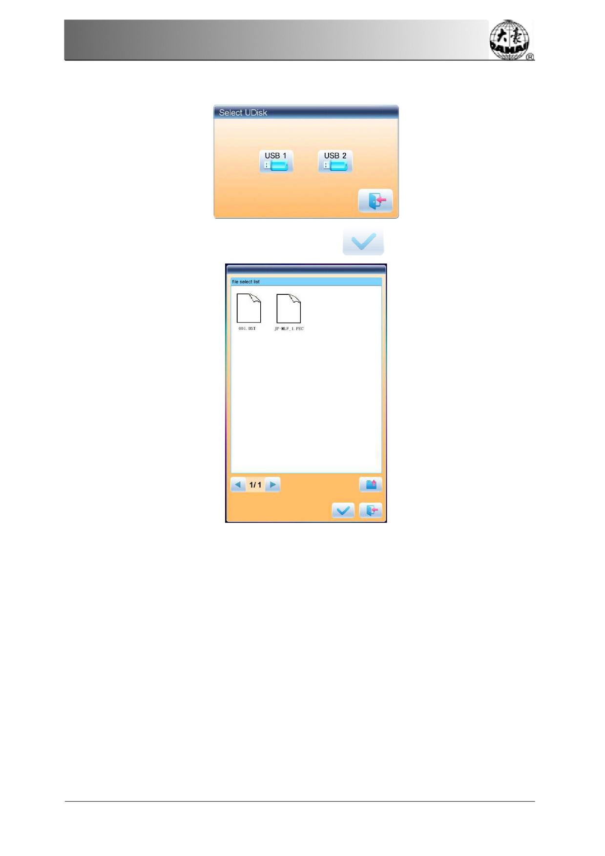
Press
76
Chapter 11
Update
of Software in Peripheral Board
5.
Select the U disk
6.
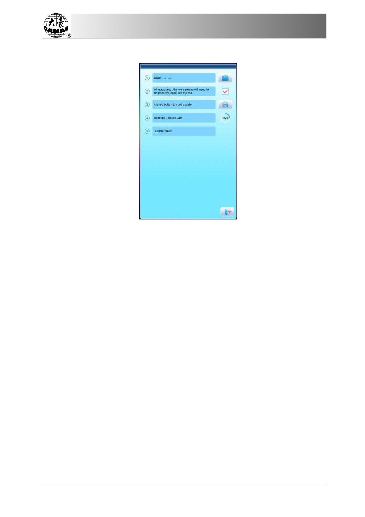
Select the program
to be updated and press
77
Chapter 11 Update of Software in Peripheral Board
7.
when system hint successful update, the update is completed.
78
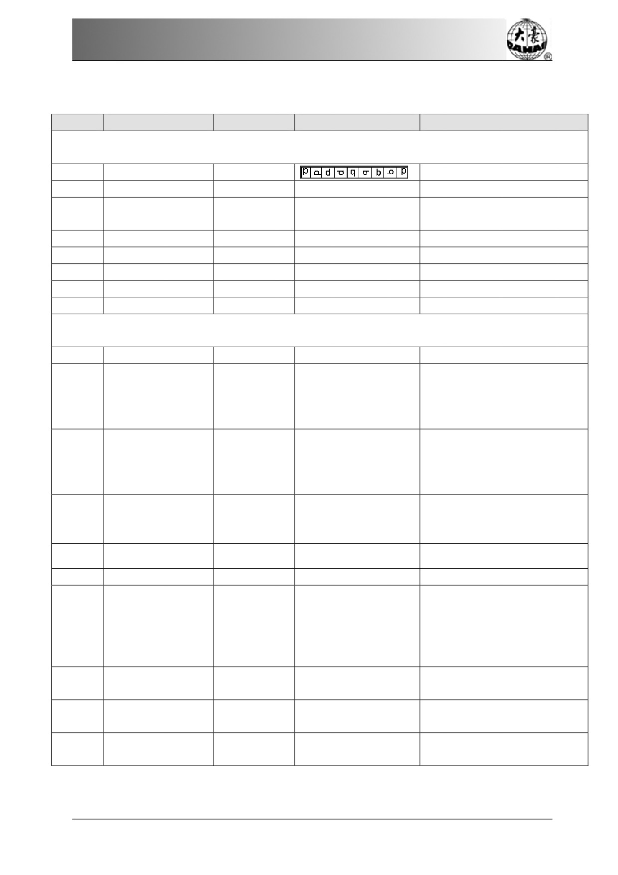
Appendix 1 Parameter
List
Appendix
1 Parameter List
No.
Name of Parameter
Default Value
Range of Value
Remarks
Common Parameters
A01
Direction
P
A02
Rotate
0
0~89
Rotating angle of the design
A03
Scale ratio of design in X /Y
X&Y Scales
100/100
50%~200%
direction
A04
Prior Mode
Rotate
Rotate,
Scale
A05
Rep. Mode
Normal
Normal Part
Not
used
A06
Rep. Prior
X
Prior
X prior, Y prior
A07
X&Y Reps
1/1
1~99
A08
X&Y Interval
0.0/0.0
-999.9~+999.9
Embroidery Assistant Parameters
B01
Auto Origin
Yes
No, Yes
Whether to automatically
repeat embroidering the
B02
To Do Cyclic Emb.
No
No, Yes
design. It often
accompanies
repetition or the
special design.
Whether to start
in
Start
for
Same
color-changing
way when the
B13
Yes
No, Yes
Colors
later
needle position is same to
the former one
Slow STI.
After
D15
0
0~3000
Patch
D16
Speed After
Patch
850
80~1000
B18
Support 3D?
Yes
No, Yes
It is
fit for high-speed machine
using
dahao servo-motor
C77
Filter Short
Stitch
Yes
No, Yes
driver. It only get effective
after
user confirm the
embroidery again.
Filtering Short Sti
0.5mm
0.1mm~0.6mm
The
same as above
C78
Len
Auto Jump
Stitch
The
same to above
C80
6mm
6.0mm~12.0mm
Len
Speed of
Fast
10
1~10
U57
ldling
79
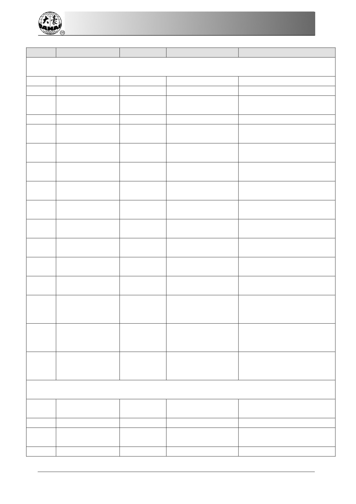
Appendix 1 Parameter List
No.
Name of Parameter
Default Value
Range of Value
Remarks
Thread-breakage Detection Parameters
B05
T. B. Detect
No
No, Yes
B11
Sti. Not T.B. Detect
8 stitch
0 stitch ~15 stitch
B06
Stop after T.B.
Yes
No, Yes
detect
B08
T.B. Back Sti.
0 stitch
0 stitch ~7 stitch
Back&Patch Count
1 stitch ~9 stitch
How many stitches to patch
B09
2 stitch
before the thread break point
Motion After Patch
Speed No Change,
B10
Speed Down
Speed Down, Stop
Set All Heads
If “Yes”, all unclosed heads do
B14
No
No, Yes
Patch
patching when patching.
T. B. Detect When
B12
No
No, Yes
Jump
T.B.Detect
1 stitch
1 stitch ~6 stitch
C28
Debouncing Sti
Upper Line Det.
C67
3
1~10
Sensitivity
Bobbin
line
C68
5
1~10
Det.Sensitivity
Upper Line Det.
C69
1 Sti
1~10 Sti.
Debouncing Sti
Bobbin line Det.
C70
5 Sti
1~10 Sti.
Debouncing Sti
Spring,
Wheel,
C90
T.B.D Device Type
Wheel
Spring+Wheel
Fault
det.board
K1
PC2220
PC2220,Other
type
Head motor Action
C91
0
0~10
Angle
Frame Parameter
Frame Curve &
C06
F4
F1~F6
Angle
B03
Over frame by Step
No
No, Yes
High Frame-Shift
C15
16
1~30
Speed
C16
Low Frame-Shift
12
1~30
80
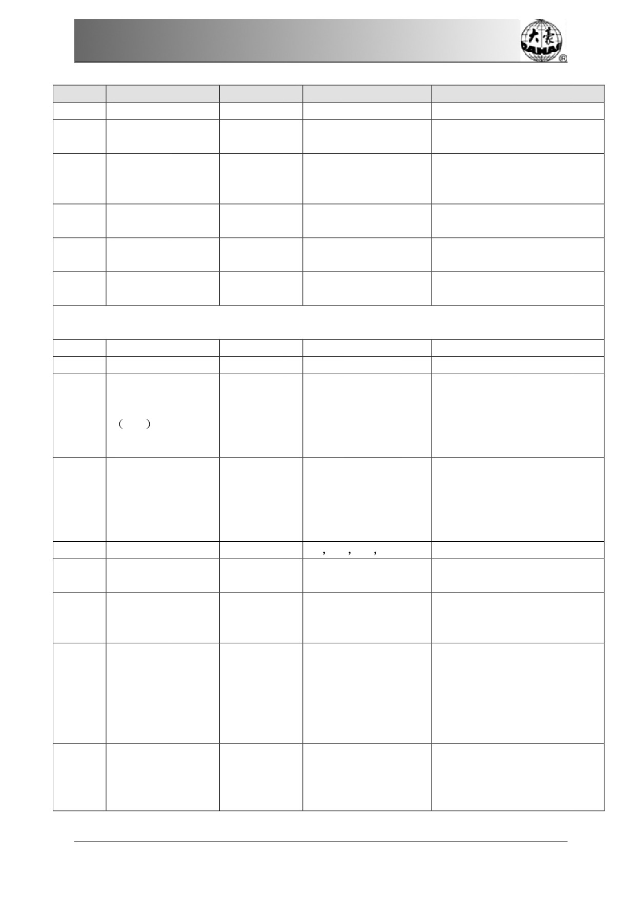
Appendix 1 Parameter
List
No.
Name of Parameter
Default Value
Range of Value
Remarks
Speed
Speed When Over
D13
16
0,1,2,…,30
frame
It is
fit for high-speed machine
X
direction
Frame
C74
230
230~280
using
Dahao servo-motor
Angle A
driver.
X
direction
Frame
C75
230
230~280
The
same as above.
Angle B
Y
direction
Frame
C76
230
230~280
The
same as above.
Angle A
Y
direction
Frame
C85
230
230~280
The
same as above.
Angle B
Main
Shaft Parameters
C07
Max. Speed
1100
250, 300, 350,…,1200
C09
Minimum Speed
400
250,300,350,…,600
1.0~10.0(common
When the stitch
length is
type machine), 3.0~
longer than the
set value, the
Shift Stitch
Length
C08
3
6.0 (high-speed
machine will lower the speed.
mm
machine using Dahao
servo-motor driver)
400~850(common
type machine), 400~
Set the rotation
speed for jump
C10
Jump Stitch
Speed
600
1100 (high-speed
stitch
machine using Dahao
servo-motor driver)
C13
Set Run Speed
80
80
90
… 150
Set the startup stitch number
C12
Startup Stitches
2
stitch
1 stitch~9 stitch
before acceleration.
Increase the value to bring
a
D02
Startup Acce.
15
1,2,3,…,30
quicker speedup
after pressing
the start key.
Range: 0~30. When the main
shaft
motor is an
electromagnetic
motor, the
C25
Set Break Para.
5
0~30
value is usually
set at 9. When
it is
a servomotor, the
parameter is usually set at
5-7.
The
parameter is invalid when
it’s a
servomotor. When it’s
an
C24
Main Motor
Para.
4
0~30
electromagnetic
motor,
increase this parameter value
81
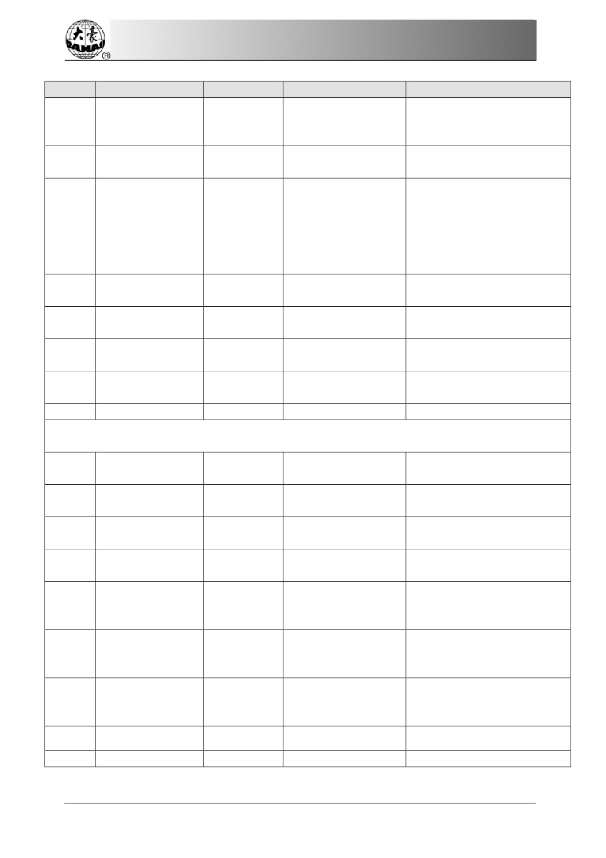
Appendix 1 Parameter List
No.
Name of Parameter
Default Value
Range of Value
Remarks
to avoid main shaft vibration
during braking. Usually it’s set
as 1.
Stop Ok bef. Pull
D14
Yes
No, Yes
Bar
The parameter is used when
the main shaft uses induction
Ratio
of
AC
motor. If the value is incorrect,
D10
0
-15% ~ +15%
Induction
the set rotation speed will be
different from the virtual
speed.
Value for Thick
C05
0
0~3
Cloth
Para. Of Needle
C26
15
0~30
Down
Lock Motor When
D53
Yes
No, Yes
Stop
Speed of Slow
C14
80
80,400
Emb
MS10
Emb.Speed
Middle
Low,Middle,H
Thread-trimming Parameters
Jump & Trim
No Trim, 1 Jump~7
C01
3 Jump
Jump
80
The parameter sets the rotation
D04
Speed after Trim
60,70,80…150
speed for lock stitch.
Slow Stitches After
C11
3 stitch
1 stitch ~7 stitch
Trim
Length of Lock Sti.
C21
0.6
0.3~1.5
(mm)
Set the lock stitch number at
Lock Num. After
C19
2
0~3
pulling the bar for embroidery
Trim
after setting the trimming
2 for most machines, 1 for
Spin Rounds for
D06
1
1,2
mini type or machines with
Brake
servo control main shaft motor.
Y
X Frame-moving, Y
C23
Action after Trim
Frame-movin
Frame-moving Move
g
Needle
Frame after Trim
No
No, Yes
C22
D03
Set Hold Startup
-4
-4~3
82
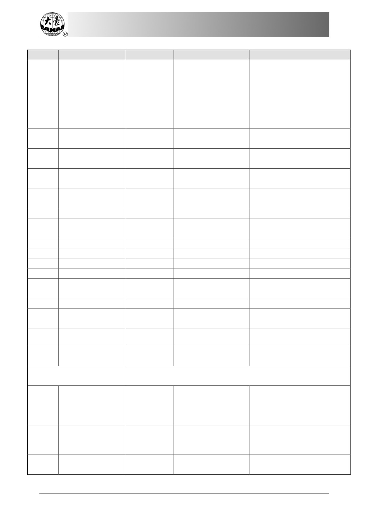
Appendix 1 Parameter
List
No.
Name of Parameter
Default Value
Range of Value
Remarks
Para.
D07
Trim is OK
Yes
No, Yes
Set the hook angle by motor.
Hook Angle
by
When user increases the value,
D08
-100
-100~+100
Motor
the hook angle is moved
backward.
Hook Distance By
E39
150
0~180
Motor
C17
Pause Trimming
No
No, Yes
Trim Length
1 is the minimum length and 8
C18
3
1~8
are the maximum length.
Speed When
D05
80
80,90,100,…,250
Trimming
C20
Lock When
Trim
Yes
No, Yes
Lock Sti Len
D48
0.7
0.3~2
bef.Trim
D49
Lock Sti bef.Trim
2
0~2
It is
fit for the machine using
0~20
Cut action start
C81
8
stepping-motor
for trimming
angle
thread.
The
same as above.
C82
Cut return angle adj
12
0~30
Cut keeper return
The
same as above.
0~99
C83
0
angle
The
same as above.
C84
Hold voltage adj
1
1~3
Speed At 1st Sti.
C95
400
60~600
Bef. Trim
Speed At 2st Sti.
C96
80
60~500
Bef. Trim
When the shear line
C93
Open
Open, 1
times, 2times
surface
Emb surface
clip
C94
Open
Open, 1
times, 2times
action way
Patch emb surface
E99
No
No, Yes
when fully
Stepping motor,
Trimming device
Stepping
H05
type
motor
Solenoid
The
same as above.
C110
Trim Machine Type
360
180, 360
Machine Parameters
83
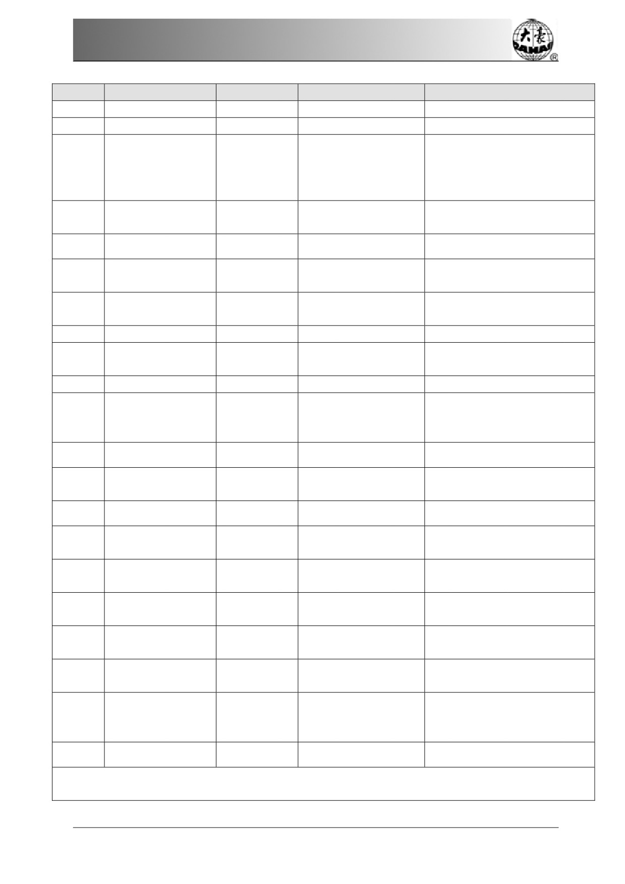
Appendix 1 Parameter List
No.
Name of Parameter
Default Value
Range of Value
Remarks
Set the value according to the
machine situation. E.g. the
value should be 9 for 9-needle
D01
Needles
6
1,2,…,MAXNEEDLE
machine. If the value is
different from the machine
needles, the color changing
will be abnormal.
Color-Change
D12
12
0~30
Speed
Openloop stepper
K2
0
0~7
change color curve
X compensation for
C49
0
0,1
mechanical gap
Y compensation for
C50
0
0,1
mechanical gap
C29
Needle of Boring
No
No, 1~7
Thread
hold
1
1~10
C71
voltage adj.
E1
DIP1
0
0~255
E2
DIP2
0
0~255
E3
DIP3
0
0~255
E4
DIP4
0
0~255
Drive
failure
Yes
No, Yes
H06
monitoring
M100
Start needle light
no
no,yes
Hat emb Speed
800
80~800
K3
limit
1
1~10
D68
Number of heads
Machine
head
162
1~1500
E45
distance
Net Parameters
It is used for setting machine
address when connected to PC.
C43
IP Address
It is not different among
different machines.
It is used for setting the subnet
C45
Subnet mask
mask of IP address when
connected to PC.
It is used for setting the
C46
Gateway
gateway of machine when
84

Appendix 1 Parameter List
No.
Name of Parameter
Default Value
Range of Value
Remarks
connected to PC
85
Appendix 2 Directions of U Disk Operation
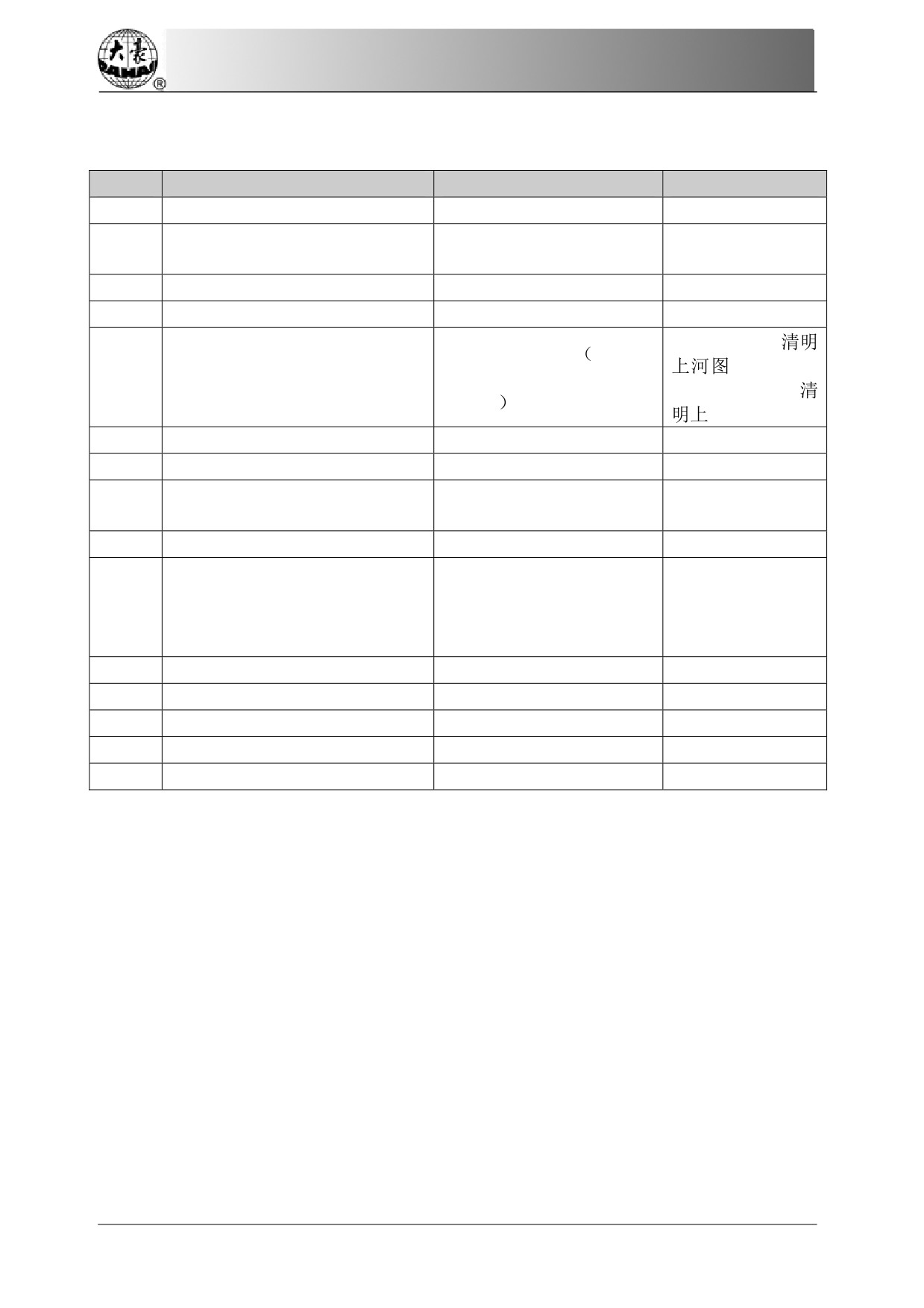
Appendix 2 Directions of U Disk Operation
No
Operations
Methods or Standards
Remarks
1
USB I/O
Same as floppy disk
Operation priority between USB
2
USB Disk
disk and floppy disk
3
Format supported by USB disk
FAT16 and FAT32
4
Support long file name
Support, but not displayed
For instance: “
DOS 8.3 mode
8 digit
.DST” will
5
File name format
prefix is viewable,suffix is
be displayed as “
3 digits
~1.DST”
6
Support file name in Chinese
Support
7
Sub-directory operation
Support
No. It could be countless
8
Sub-directory limitation
in theory
9
File number in one sub-directory
400
Back to disk management
Reading & writing error/ change
or design management
10
USB
interface, insert the disk
again.
11
Multi-logical disks in one USB
Support
12
Formatting USB
Support
13
Installation of the letter base
Not Support
14
Software update
Support
15
Special character in file name
Support, except “$”.
86
Appendix 3 Automatic Position
Limitation Function Inst
ructions fo
r Apparel
Embroidery
Appendix 3Automatic Position Limitation Function
Instructions
for Apparel Embroidery
A Working Principle
The automatic
position limitation function of single-head
embroidery
machine
controller
is to determine the
embroidery
range of the frame by
setting the
distance from the center of the
frame to
the origin
(that is X-/Y position
limitation
optical coupler) and the actual frame size
(unit: mm). If embroidery is to be done beyond
such range, the controller will
activate
automatic protection to prevent damage to
the mechanical parts
of the embroidery machine.
B Setting Method
1
Set Frame
Origin
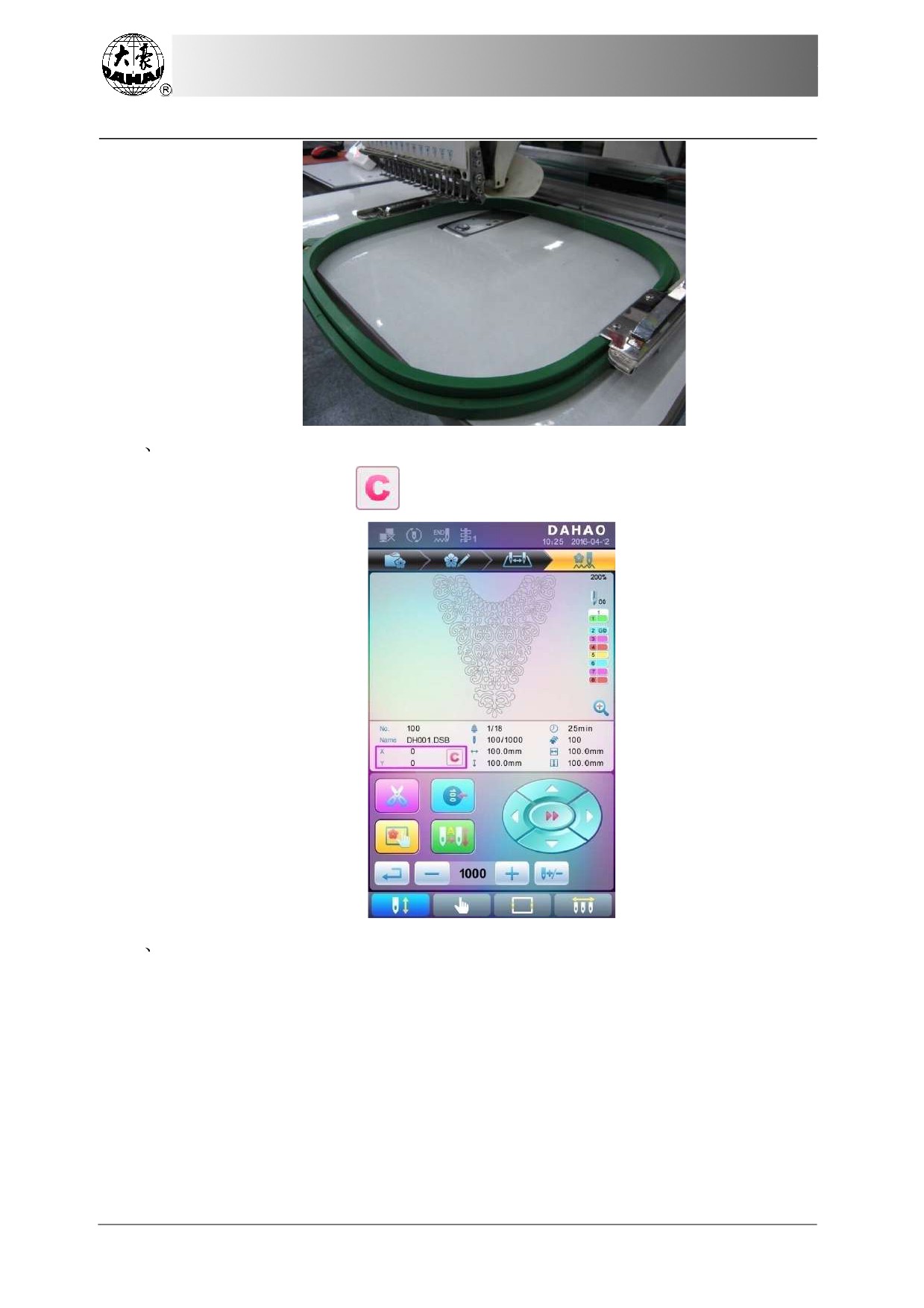
Press
key, then press
key, to enter the following
interface.
Select " Automatic Origin Search", to enter the interface
to search origin automatically;
the frame will search and determine the
origin automatically; press "
" key to
quit.
87
Appendix
3 Automatic Position Limitation Function Instr
uctions for
Apparel
Embroidery
2
Clear XY Displacement
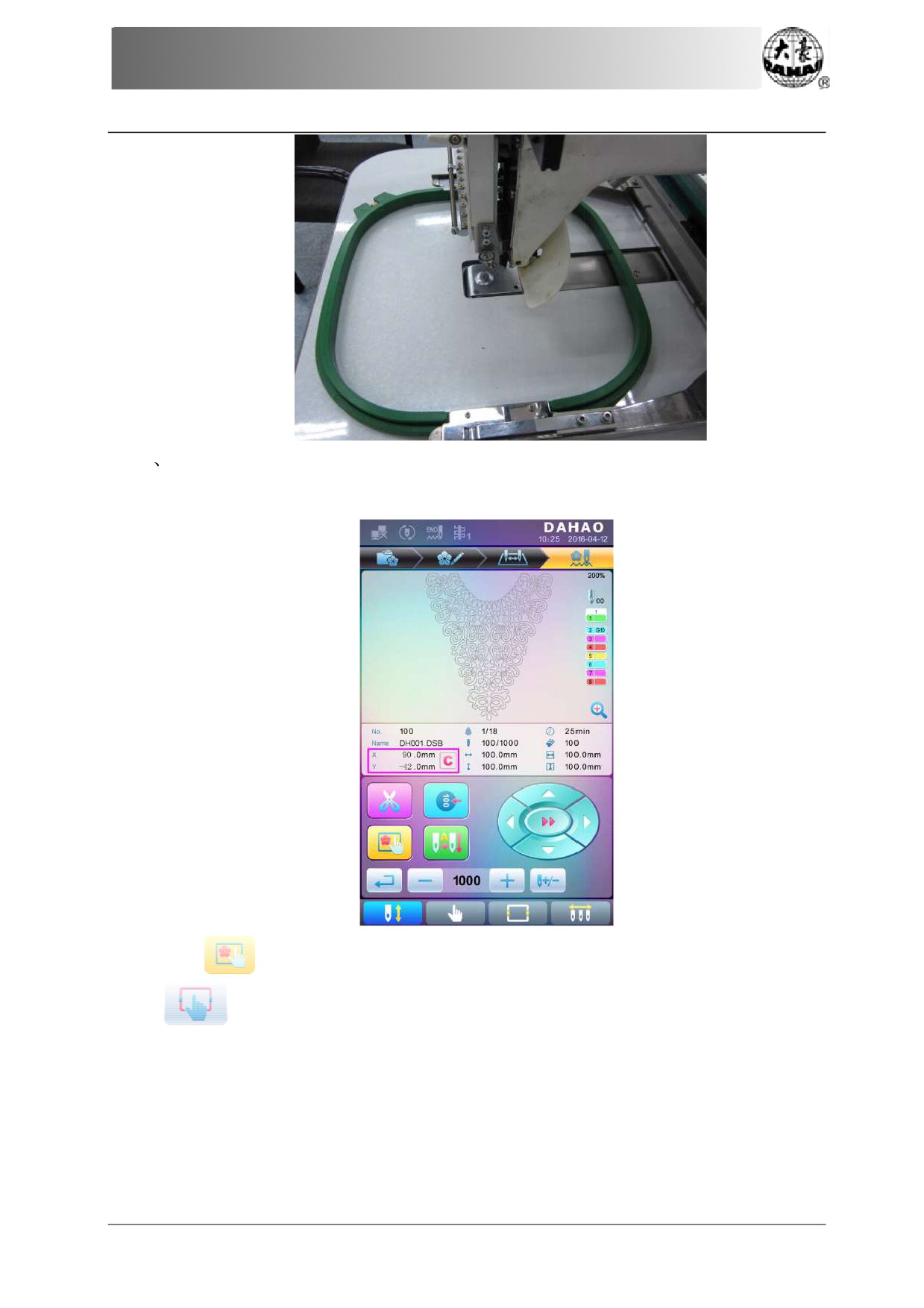
In the main interface, press "
" key to clear
the XY displacement displayed here.
3
Manual Frame-moving
In the main
interface,
click the frame-moving key to move the frame to overlap its
center with the needle hole.
88
Appendix 3 Automatic Position
Limitation Function Inst
ructions fo
r Apparel
Embroidery
4
Set Frame
Center and
Size
In
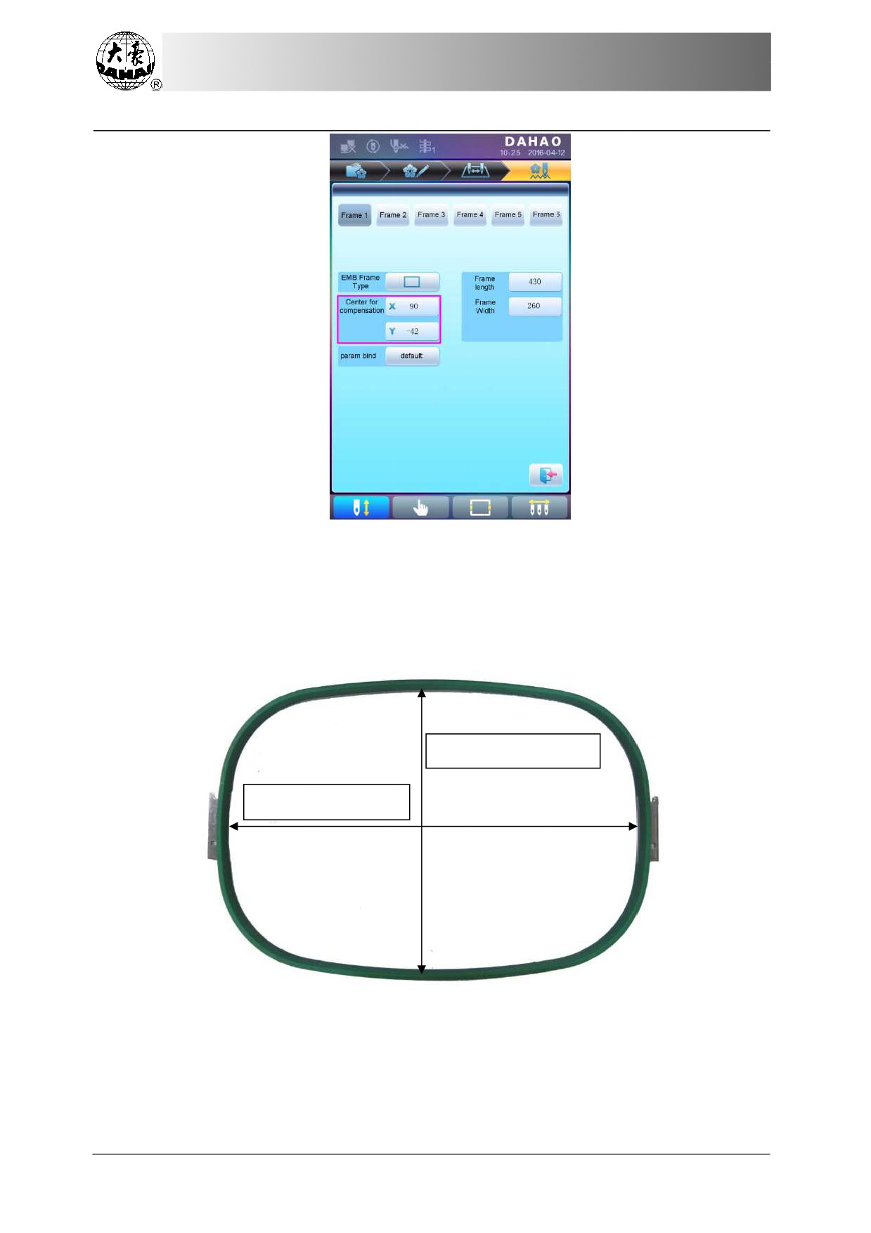
the main interface, check the coordinates of XY, which is the position of frame
center.
Press "
" key, to enter the interface for
frame selection and position setting; then
press "
" key, to enter
the interface for setting related parameters, where user
can input
the coordinates of XY in the main interface.
89
Appendix
3 Automatic Position Limitation Function Instr
uctions for
Apparel
Embroidery
There are four
parameters: "X direction center" means the distance at X
direction
between
the frame center and X- direction position limitation optical
coupler; "Y
direction
center"
means the distance at Y direction between
the frame center and Y+ direction
position limitation
optical coupler. "X
direction
frame size" means the embroidery range
of the frame at X
direction; "Y direction frame size" means the embroidery range of the frame
at Y direction.
Y Frame Actual Size W
X FrameActual Size L
"X direction frame size" and "Y direction frame
size" should
be set according to the actual
size of different frames. Note:
this parameter need be set according to the
actual embroidery
range of the frame, for the apparel frame is
usually not square.
90
Appendix 3 Automatic Position
Limitation Function Inst
ructions fo
r Apparel
Embroidery
C Cancel Position Limitation
Set
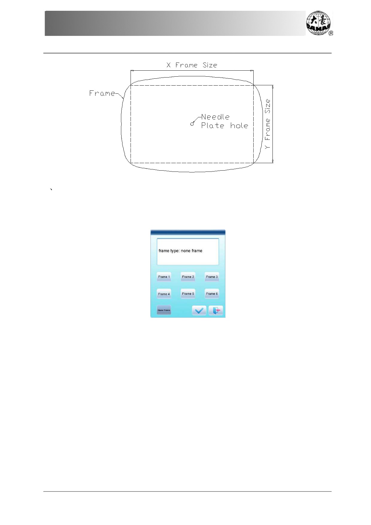
"Frame Selection" as
"No Frame", the position limitation function will be
canceled
and the
software protection for
the frame
of flat embroidery will also become invalid.
91
Appendix
3 Automatic Position Limitation Function Instr
uctions for
Apparel
Embroidery
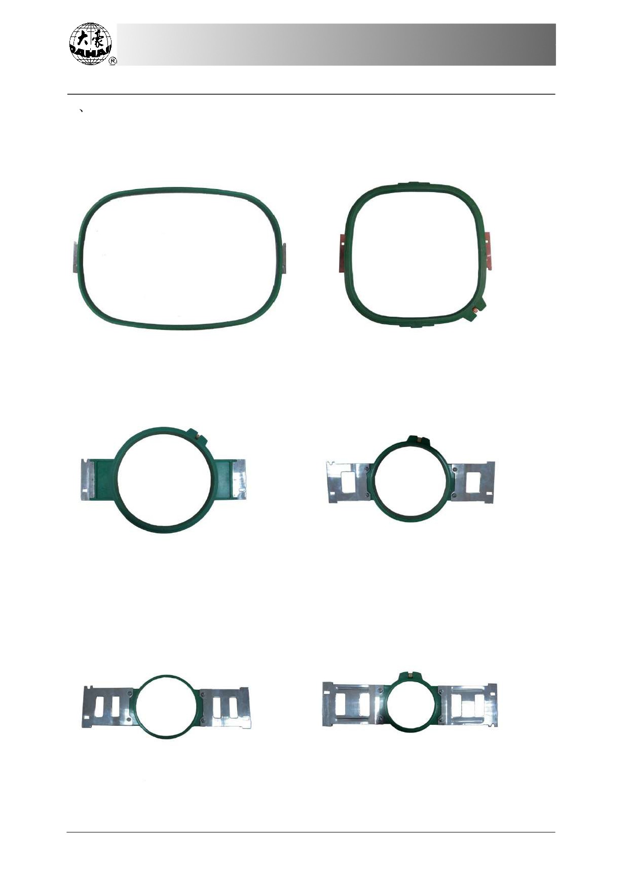
D Common Frame
Size (Unit: mm)
Frame 1:
Frame 2:
Size: 550×375
Size: 290×290
Embroidery Range:
430×260
Embroidery
Range: 230×230
Frame 3:
Frame 4:
Size: 200
Size: 150
Embroidery Range:
150
Embroidery
Range: 100
Frame 5:
Frame 6:
Size: 120
Size: 90
Embroidery Range: 90
Embroidery
Range: 40
92
/Appendix 4 A15 Controller Operation Quick Guide
Appendix 4 A15 C
ontroller Operation Quick
Guide
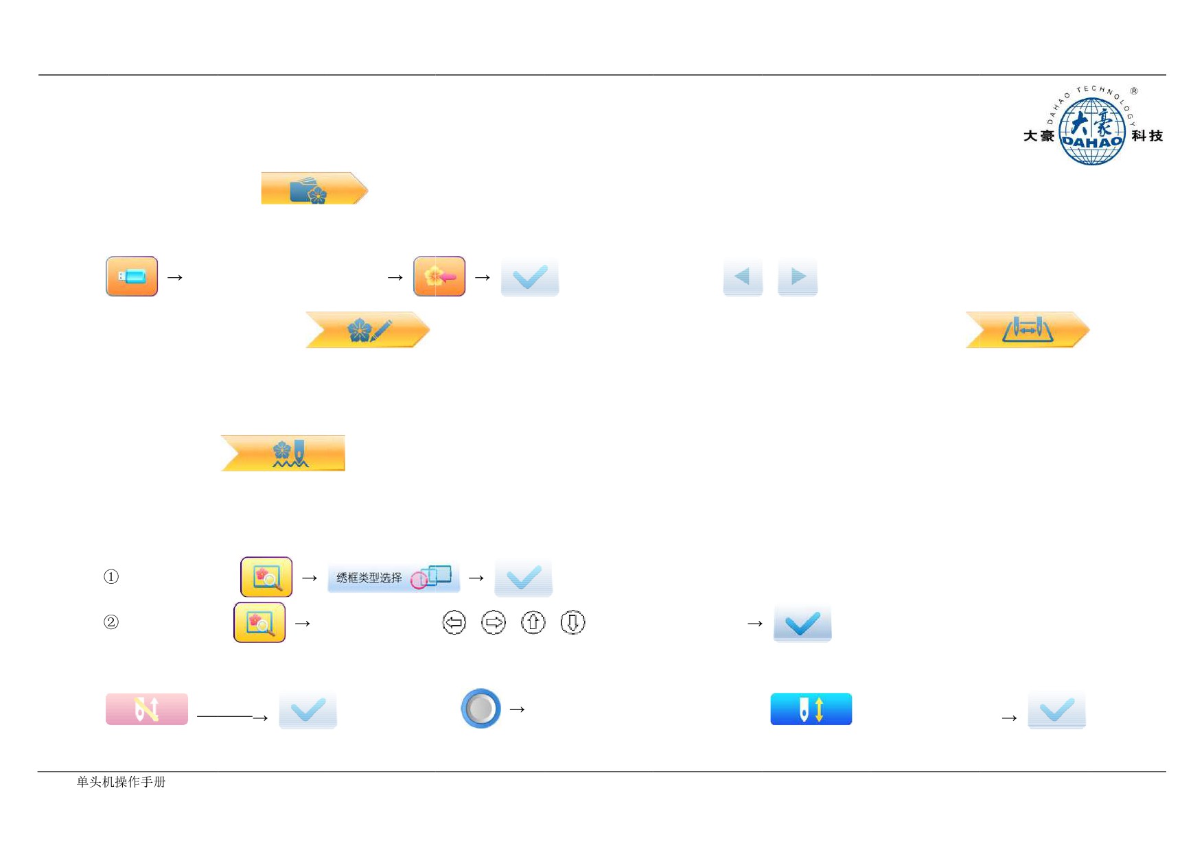
Part I. Embroidery
Pattern Management "
": memory
pattern preview,
letter pattern operation, delete pattern, pattern input/output, pattern function setting, etc.
A
Input Pattern
B. Select Pattern for
Embroidery
Use page keys to select
patterns
,
: use page keys to select pattern
Common Parameter Setting "
": direction, angle, X/Y scaling,
priority Color-changing Sequence Setting "
":
setting, etc.
repeat,
appliqué, needle
bar color setting,
etc.
C
Modify Embroidery Parameters: A01-A08: click to set.
D. Under this Interface: set color-changing sequence.
Main Interface "
": thread trimming, main shaft
jog, frame setting, color-changing
and start mode setting, manual frame-moving, speed
adjustment, empty
feed, etc.
E
Frame Selection and Position
Frame Selection:
Frame Position:
Use direction keys
,
,
,
to adjust frame position
F
Embroidery
Confirmation
G. Start Embroidery
H. Release Embroidery Confirmation
Confirm
Release Confirmation
Start
BECS-
93
Appendix 4 A15
Controller Operation Quick Guide
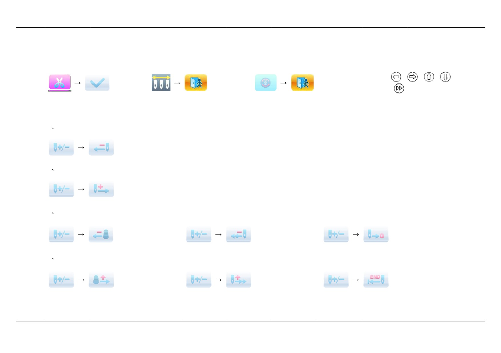
Part
II. Manual Operation
A. Manual Trimming
B. Manual Color-changing
C. Main Shaft Jog
D. Manual Frame-moving
Direction Keys:
,
,
,
;
Speed
Shift Key:
E. Empty Feed
1
Empty Feed and Return at
Low Speed
: (1) click once to return by 1 stitch; (2) hold pressing for 2s
to return continually;
2
Empty Feed and Advance at low Speed
: (1) click once to advance
by 1 stitch; (2) hold pressing for 2s to advance continually;
3
Locate the
Last Color-changing Code
5. Empty Feed
and Return at High Speed
7. Return to Embroidery Start
Point
4
Locate the
Next Color-changing Code
6. Empty Feed
and Advance at
High Speed
8. Return to Embroidery Stop
Point
95