Takeuchi Hydraulic Excavator TB175 (No. 17512105~). Operator's Manual (2007) - page 13
 

  Index      Manuals     Takeuchi Hydraulic Excavator TB175 (No. 17512105~). Operator's Manual (2007)


Search            copyright infringement  


Content      ..     11      12      13     


Takeuchi Hydraulic Excavator TB175 (No. 17512105~). Operator's Manual (2007) - page 13


OPTIONS

192

Hydraulic Breaker

For handling of the breaker, read the
hydraulic breaker ’s manual, provided
separately.

IMPORTANT: When mounting devices,
select devices suited for this machine.
For advice on selecting device, contact a
Takeuchi sales or service outlet.

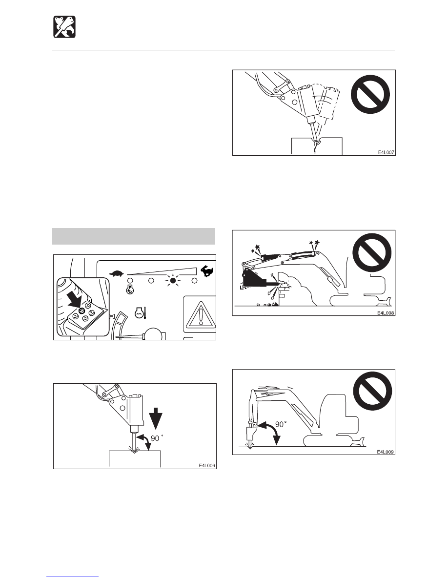
Precautions on Operating

¡

Run the engine with 75% the maximum
speed.

¡

Pound with the chisel perpendicular to the
surface you are pounding.

¡

When pounding, press the chisel properly
against the object to be broken so as to
avoid pounding the air.

Pressing force

L

H

L3D008

FC

¡

Do not pry with the chisel, and do not pry
while pounding.

¡

Do not move the chisel while pounding.

¡

Do not pound continuously for over 30
seconds on the same surface.

¡

Do not pound with the cylinder fully
extended or contracted (at the stroke end).
Leave a margin of at least 5 cm.

¡

Do not pound with the arm perpendicular
to the ground surface.


193

OPTIONS

Hydraulic Breaker

¡

Do not drop the breaker itself on the object
to be broken in order to break it.

¡

Do not move objects to be broken or rocks
with the breaker itself.

¡

Slew occasionally to cool the engine.

¡

If a hydraulic hose is vibrating abnormally,
nitrogen gas may be leaking from the
accumulator. Have an inspection as soon
as possible.

Replace the hydraulic oil
regularly!

When using a hydraulic breaker, the oil
deteriorates quicker than during normal
digging. Be sure to replace the hydraulic oil
and return filter element.

¡

Failure to replace these in time can lead
to damage to the machine and breaker’s
hydraulic systems. In order to improve the
service life of the hydraulic systems, be
sure to replace the hydraulic oil and return
filter element after the number of hours
shown on the diagram below.

¡

Clean the suction strainer when changing
the return filter element.

Replacement Interval (Hours)

Item

Hydraulic Oil Filter Element

1st time

25

2nd time

100

Periodically

600

200

When the breaker operating ratio is 100%

2000

1500

1000

500

0

40

100

80

60

20

Breaker operating ratio (%)

Replacement inter

v

al (H)

N0G036

Replacement interval 
for hydraulic oil

Replacement 
interval for filter element


194

OPTIONS

3-Holes Bucket

The digging capacity increases when the
bucket’s link arm installation position is
switched from (A) to (B). However, this
shortens the bucket stroke.

• Struck capacity (SAE):

0.210 m

3

 (0.275 cu. yd.)

• Rated capacity (SAE):

0.261 m

3

 (0.341 cu. yd.)

Changing the Link Arm
Installation Position

Refer to page 134 “Replacing the Bucket” in
the manual.

OL1L170

A

B

OL1L180


195

OPTIONS

Travel Alarm

Factory option
An alarm is sounded when the machine
travels and stops when traveling is stopped.
If the alarm does not sound when the
machine travels, the fuse may be blown.
Inspect the fuse.

 WARNING

If the fuse which has just been replaced
should blow again, there is a problem in
the electrical system. This could cause
fires. Contact a Takeuchi dealer.

1. Park the machine in a safe place.
2. Set the starter switch to OFF.
3. Open the fuse box cover (1).
4. Inspect for blown fuse.
5. If a fuse is blown, replace it with a spare

fuse of the same capacity.

Fuse Layout and Circuits Protected

Capacity

Capacity

Protected circuit

Protected circuit

15A Horn,

Interior Light

10A Proportional control

solenoid

20A Lights

20A Wiper

5A

Radio

5A

Heater

30A Air conditioner

(option)

20A Instrument cluster,

Lift alarm (option)

3A

Throttle controller
(B)

1A

Stop solenoid hold

10A External power socket,

Travel alarm

10A Cigarette lighter

10A Lever lock

10A Automatic-glow

20A Throttle controller

(ACC)

20A Feed pump,

Stop solenoid timer

E4J007

Normal

Blown

10

10

10

20

20

10

20

10

5

10

5

10

20

20

20

10

1

L3J002


196

OPTIONS

Load Safety Device

The load safety devices include an
emergency shut-off valve and an overload
warning device. The emergency shut-off
valve stops the boom or arm part way
through a fall. The overload warning device
sounds an alarm when an excessive load is
applied.

Emergency shut-off valve

When the hose of the boom or arm cylinders
are ruptured and the boom or arm falls, the
emergency shut-off valve is activated and
stops the boom or arm part way through the
fall.

 WARNING

If the boom or arm drops and the
emergency shut-off valves are activated,
immediately move away from the
suspended object.

Mono-Boom / Type A or B

2-Piece Boom / Type B

Intermediate Boom / Type B

Arm / Type B

If the emergency shut-off valves (1) or (2)
are activated, immediately set the operating
lever to the neutral position. Do not move
the operating lever to the boom or arm
lowering side. Contact a Takeuchi dealer for
maintenance.

Type A

1. Check for safety in the working area and

for stability of the machine and lifted load.

2. Loosen the emergency shut-off valve’s

lock nut (3) and stem (4) to lower the
boom.

3. Check for stability of the hoe attachment

and load.

N0L003

2

L3L014

1

3

4


197

OPTIONS

Overload Warning Device

If a weight greater than the machine is
designed to lift is lifted, the overload warning
device is activated and a horn is sounded
(when the overload warning switch is turned
on).

 WARNING

Continuing to apply the load after the
overload warning horn sounds could
result in the machine tipping over or the
emergency shut-off valve being activated.
If the horn sounds, stop operating the
machine and lighten the load.

Overload warning switch (2)

O position .... OFF
 I position .... ON When the emergency
shut-off valve is activated, the overload
warning horn stops. (This is because the
pressure sensor can no longer detect
hydraulic pressure.)

Load Safety Device

L3L0061

2

N0L0061

3

4

5

2

4. Tighten the stem (4) secure it with the lock

nut (3).
Tightening torque:
• Stem (4) 1.0 to 1.5 N·m (0.7 to 1.1 ft-lb.)
• Lock nut (3) 3.2 N·m (2.4 ft-lb.)

Type B
If the engine can be started, the boom or
arm can be lowered with the operating lever.
Check for safety, then slowly lower the boom
or arm.
If the engine cannot be started, the boom or
arm can be lowered using the procedure
described below.

1. Check for safety in the working area and

for stability of the machine and lifted load.

2. Remove the cap (3).
3. Loosen the lock nut (4).
4. Tighten the stem (5) to lower the boom or

arm.

5. Check for stability of the hoe attachment

and load.

6. Loosen the stem (5) secure it with the lock

nut (4).


198

OPTIONS

Fuel Supply Pump

This device automatically supplies fuel to the
fuel tank and stops automatically when the
fuel tank is full.

 DANGER

Do not use the fuel supply pump for
gasoline or hydraulic oil.  Doing so could
result in explosion or damage. Only use
the fuel supply pump for diesel fuel.

1. Open the front cover.
2. Insert the pump’s nozzle (1) in the fuel

supply tank.

3. Press the switch (2).

The pump stops automatically once the
fuel tank is full.

2

1

L3L013


199

OPTIONS

Accumulator

Operating the Machine with
Accumulator

On machines equipped with an accumulator,
the residual pressure in the auxiliary
hydraulic circuits and the working equipment
can be released within a specific amount of
time (within 10 minutes) after the engine is
stopped.

Releasing the residual pressure
After using the machine, pressure remains
in the hydraulic circuits. This is called the
residual pressure. Use the procedure below
to release the residual pressure as
necessary.

Perform the operation to release the residual
pressure within 10 minutes after stopping the
engine.

1. Press the decel. button and idle the engine

at low speed.

2. Lower the bucket and dozer blade to the

ground.

3. Check that the safety lock lever is in the

released position.

4. Stop the engine.
5. Turn the starter switch to the ON position.

6. Press both the first auxiliary hydraulic

buttons (A) and (B) several times to
release the residual pressure in the
circuitry.

7. Move or press the second / fourth auxiliary

hydraulic switches (C / G) and (D / H)
several times to release the residual
pressure in the circuitry.
When equipped with fourth auxiliary
hydraulics.
a. Press the selector button (2nd or 4th

Aux.) to change over to operation of the
second auxiliary hydraulics.

b. Move or press the second / fourth

auxiliary hydraulic switches to the right
and left several times.

8. Move all the control levers and pedals

several times in all directions to release
the pressure from the working equipment
circuitry.

9. Raise the safety lock lever to engage the

lock.

Lowering the boom when the engine has
stopped.
Perform this operation within 10 minutes after
stopping the engine.
1. Check that the safety lock lever is in the

released position.

2. Check that the starter switch is in the ON

position.

3. Push the operating lever slowly forward

to lower the boom.

L3L035

B

A


200

OPTIONS

Second Auxiliary Hydraulic Lines

 WARNING

Oil may spurt out if caps or filters are
removed or pipes disconnected before
releasing the pressure in the hydraulic
system.

¡

¡

¡

¡

¡

When disconnecting hoses, release the
internal pressure before removing.

These lines deliver the hydraulic oil
necessary for operating a hydraulic
attachment.

Stop valve .....

S

 : Closed  

O

 : Open

Connecting the Hydraulic Circuits
To connect the attachment hydraulic lines,
use the following procedures:
1. Release the pressure remaining in the

lines then close the stop valve.

When equipped with accumulator:
Refer to page 201 “Releasing the residual
pressure”.
2. Remove the plugs.
3. Connect the attachment hydraulic lines to

ports (c) and (d).

4. Open the stop valves.
5. When connecting is complete, purge air

from the hydraulic lines.
a. Start and run the engine at low idle with

no load for 10 minutes.

Second Auxiliary Hydraulics

b. With the engine running at low idle

operate the auxiliary hydraulic switches
repeatedly (approx. 10 times) to purge
air from the hydraulic lines.

c. Stop the engine and wait for more than

5 minutes until bubbles escape from the
hydraulic oil in the tank.

IMPORTANT: Follow the procedures for
purging air as instructed by the
attachment manufacturer if specified to
do so.

6. Check for leaks.

d

c

L3L036

S

O


201

OPTIONS

Second Auxiliary Hydraulics

Second Auxiliary Hydraulic
Switches

Slider switch (Proportional control) and
Buttons

Move or press those switches to control the
flow of the oil in the second auxiliary hydraulic
lines.
(C) ..... Hydraulic oil flows to left auxiliary

line(c)

(D) ..... Hydraulic oil flows to right auxiliary

line(d)

¡

When the safety lock lever is set to the
lock position, this control is locked.

Disconnecting the hydraulic circuits
1. Release the pressure remaining in the

lines then close the stop valve.
When equipped with accumulator:
Refer to “Releasing the residual pressure.”

2. Disconnect the lines from ports (c) and (d).
3. Install the plugs.

When equipped with accumulator
Releasing the residual pressure
After using the auxilliary hydraulic circuits,
pressure remains in the circuits. This is called
the residual pressure. Release this residual
pressure before disconnecting the lines.
1. Stop the engine.
2. Turn the starter switch to the ON position.
3. Fully lower the safety lock lever.

4. Within 10 minutes after the engine comes

to a complete stop, move or press the
second auxiliary hydraulic switches to the
right and left several times.

5. Raise the safety lock lever to engage the

lock.


202

OPTIONS

Third Auxiliary Hydraulics

Third Auxiliary Hydraulic Lines

 WARNING

Oil may spurt out if caps or filters are
removed or pipes disconnected before
releasing the pressure in the hydraulic
system.

¡

¡

¡

¡

¡

When disconnecting hoses, release the
internal pressure before removing.

These lines deliver the hydraulic oil
necessary for operating a quick attachment.

Connecting the Hydraulic Circuits
To connect the attachment hydraulic lines,
use the following procedures:
1. Release the pressure remaining in the

lines.
Refer to “Releasing the residual pressure”.

2. Remove the plugs.
3. Connect the attachment hydraulic lines to

ports (e) and (f).

4. When connecting is complete, purge air

from the hydraulic lines.
a. Start and run the engine at low idle with

no load for 10 minutes.

b. With the engine running at low idle

operate the auxiliary hydraulic switches
repeatedly (approx. 10 times) to purge
air from the hydraulic lines.

c. Stop the engine and wait for more than

5 minutes until bubbles escape from the
hydraulic oil in the tank.

IMPORTANT: Follow the procedures for
purging air as instructed by the
attachment manufacturer if specified to
do so.

5. Check for leaks.


203

OPTIONS

Third Auxiliary Hydraulics

1

2

L3L029

L3L030

Third Auxiliary Hydraulic Switch
and Button

Press those switch and button to control the
flow of the oil in the third auxiliary hydraulic
lines.
When the safety lock lever is released after
the engine is started, hydraulic oil constantly
flows in pipe (e). When button (1) and switch
(2) are pressed simultaneously, the oil flow
switches to pipe (f). When this happens, the
pressure of pipe (e) drops, an alarm is
sounded and the warning lamp lights. For
safety, only operates when both button (1)
and switch (2) are pressed.

Disconnecting the hydraulic circuits
1. Release the pressure remaining in the

lines.
Refer to “Releasing the residual pressure”.

2. Disconnect the lines from ports (e) and

(f).

3. Install the plugs.

Releasing the residual pressure
After using the auxilliary hydraulic circuits,
pressure remains in the circuits. This is called
the residual pressure. Release this residual
pressure before disconnecting the lines.
1. Stop the engine.

(The residual pressure is released from
the (e) port line.)

Third Auxiliary Hydraulics
Warning Lamp

This lamp illuminates and an alarm sounds
when the third auxiliary hydraulic pressure
drops abnormally while the engine is running.


204

OPTIONS

Fourth Auxiliary Hydraulics

Fourth Auxiliary Hydraulic Lines

 WARNING

Oil may spurt out if caps or filters are
removed or pipes disconnected before
releasing the pressure in the hydraulic
system.

¡

¡

¡

¡

¡

When disconnecting hoses, release the
internal pressure before removing.

These lines deliver the hydraulic oil
necessary for operating a hydraulic
attachment.

Connecting the Hydraulic Circuits
To connect the attachment hydraulic lines,
use the following procedures :
1. Release the pressure remaining in the

lines.
When equipped with accumulator:
Refer to page 199 “Releasing the residual
pressure”.

2. Remove the plugs.
3. Connect the attachment hydraulic lines to

ports (g) and (h).

4. When connecting is complete, purge air

from the hydraulic lines.
a. Start and run the engine at low idle with

no load for 10 minutes.

b. With the engine running at low idle

operate the auxiliary hydraulic switches
repeatedly (approx. 10 times) to purge
air from the hydraulic lines.

c. Stop the engine and wait for more than

5 minutes until bubbles escape from the
hydraulic oil in the tank.

IMPORTANT: Follow the procedures for
purging air as instructed by the
attachment manufacturer if specified to
do so.

5. Check for leaks.

Selector Button (2nd or 4th Aux.)

This button changes from the fourth auxiliary
hydraulics operation to the second auxiliary
hydraulics operation.
Press this button to change over to operation
of the second auxiliary hydraulics. The
second auxiliary hydraulics operation
indicator lamp will light. One more press of
this button will result in a return to fourth
auxiliary hydraulics operation. Actual
operation is performed with the second /
fourth auxiliary hydraulic switches.


205

OPTIONS

Second / Fourth Auxiliary
Hydraulic Switches

Slider switch (Proportional control) and
Buttons

Move or press those switches to control the
flow of the oil in the fourth auxiliary hydraulic
lines.

(G) ..... Hydraulic oil flows to left auxiliary

line(g)

(H) ..... Hydraulic oil flows to right auxiliary

line(h)

¡

When the safety lock lever is set to the
lock position, this control is locked.

Disconnecting the hydraulic circuits
1. Release the pressure remaining in the

lines.
When equipped with accumulator :
Refer to page 199 “Releasing the residual
pressure”.

2. Disconnect the lines from ports (g) and

(h).

3. Install the plugs.

Fourth Auxiliary Hydraulics

Selector Button (2-Piece boom)

 WARNING

Pressing (switching ON or OFF) the
selector button while the boom swing
pedal is depressed is dangerous, since
the attachment will move unexpectedly.
Always set the boom swing pedal back
to the neutral position before operating
the selector button.

This button changes from the boom swing
operation to the intermediate boom
operation.
Press this button to change over to operation
of the intermediate boom . The intermediate
boom operation indicator lamp will light. One
more press of this button will result in a return
to boom swing operation. Actual operation
is performed with the boom swing pedal.
Operation of the first auxiliary hydraulic
switch push button: left side (A) only.


206

OPTIONS

Air Conditioner

CAUTIONS ON USE

Ventilate periodically

¡

When using the air conditioner over an
extended period of time, open the
windows about once each hour to let in
fresh air.

¡

Your eyes may become irritated if you
smoke while using the air conditioner. If
this happens, open the windows to let in
fresh air. Cigarette smoke particularly
irritates the eyes when using the air
conditioner because the humidity in the
cabin drops and the eyes’ membranes
tend to become dry.

¡

If the outside air is dirty, set the air
conditioner to the recirculation mode.

Always maintain good visibility

Working with the windows dirty or fogged
restricts visibility and is dangerous. Always
clean dirt and moisture off the windows
before working.

¡

The windows tends to get foggy when the
humidity is high. If this happens, turn on
the air conditioner and use outside air and
the defroster to get rid of the fog.

¡

If the air conditioner is set to high when
using the defroster, the difference between
the external and internal temperatures
increases, and fog may form on the
outside of the windows. If this happens,
either turn the air conditioner off or turn
the temperature control dial clockwise to
increase the internal temperature.

¡

Mist may blow out of the air outlets. This
is not a malfunction. When moist air
passes through the air conditioner unit’s
evaporator, water particles in the air freeze
and are emitted as mist.

Do not overcool

For health purposes, the air inside the cab
should be kept at a temperature at which you
feel a little cool when entering the cab from
outside (a difference of 5 to 6

°

C (9 to 11

°

F)).

Be careful to adjust the temperature properly.

Do not turn the air conditioner on
until the engine is started

To avoid placing an excessive load on the
compressor, wait until the engine is started
and is running smoothly before turning on
the air conditioner.

Let hot air out first

If the excavator has been parked in the sun,
open the windows or door to let the hot air
out of the cab before using the air conditioner.

Caution on refrigerant (gas)

Exposure of the eyes or hands to the cooler’s
refrigerant could result in blindness or
frostbite. Never touch the refrigerant or
loosen the parts of the cooling circuit.
Should the refrigerant gas leak, keep flames
away.


207

OPTIONS

Air Conditioner

NAMES OF COMPONENTS

  1. Defroster
  2. Condenser
  3. Receiver drier
  4. Foot outlets
  5. Back outlets
  6. Control panel
  7. Compressor
  8. Air conditioner unit
  9. External air duct
10. Filter

Control Panel

11. Air conditioner switch
12. Temperature control dial
13. Fan switch
14. Airflow mode control dial

12

13

14

11

L3T0021

1

L3T001

2

3

4

5

5

6

7

10

8

9


208

OPTIONS

Air Conditioner

Air Conditioner Switch

IMPORTANT: To  avoid placing an
excessive load on the compressor, wait
until the engine is started and is running
smoothly before turning on the air
conditioner.

Use this switch to turn the air conditioner ON
and OFF.  When this switch is pressed while
the engine is running and the fan switch is
ON, the air conditioner turns on.  Press the
switch again or turn the fan switch OFF to
stop the air conditioner.
O ...... OFF
 I ....... ON
Supplement: To prevent leakage of coolant
gas from the compressor’s seal, operate the
air conditioner at least once a week,
regardless of the season.
Supplement: The air conditioner will not
function if the temperature in the cab is low
(about 3

°

C (38

°

F) or lower).

Temperature Control Dial

Use this dial to adjust the air temperature.
COOL ..... To lower the temperature
WARM .... To increase the temperature
Supplement: No warm air is emitted if the
temperature of the engine coolant is low.

Fan Switch

Use this switch to adjust the fan speed in
three steps. At the OFF position, the air
conditioner is also OFF.
OFF ........ Fan and air conditioner off

............. Low
............. Medium

............ High

L3T006

L3T005

COOL

WARM

L3T003


209

OPTIONS

Air Conditioner

Airflow Mode Control Dial

Use this dial to select recirculation or fresh
air intake.

............... Recirculation
• To cool or heat the cab quickly
• When external air is dirty

CENTER .... 50% fresh air intake

• To let in fresh air
• To ventilate while cooling or heating the

cab slowly

............. Fresh air intake

• To let in fresh air
• To remove fog from the windows
• To ventilate while cooling or heating the

cab

Outlets

Move the louvers up and down or left and
right to adjust the air flow direction and
amount.

OPERATION

Heating and Dehumidifying
(in cold weather or when the
humidity is high)

After starting the engine, turn the air
conditioner ON and adjust the switches as
shown in the diagram above.
The outflow slot of foot area and the outflow
slots of the defroster can be directed at the
front window.
Warm, dehumidified air blows on the front
window, preventing fogging.
Set the temperature control dial and fan
switch to the desired positions.

Cooling

 CAUTION

¡

¡

¡

¡

¡

When the air conditioner is set to the
recirculation mode, the air in the cab
gradually becomes dirty, so switch to
external air to ventilate once a
comfortable temperature is reached.

¡

¡

¡

¡

¡

Excessive cooling can be harmful to
your health.  It is best to keep the air
inside the cab only about 5 to 6

°

C (9 to

11

°

F) cooler than the outside air.

¡

¡

¡

¡

¡

If the excavator has been parked in the
sun, open the windows or door to let
the hot air out of the cab before using
the air conditioner.

L3T004

L3T007

L3T008


210

OPTIONS

Air Conditioner

After starting the engine, turn the air
conditioner ON and adjust the switches as
shown in the diagram above.
Set the temperature control dial and fan
switch to the desired positions.

Quick cooling

To cool the cab quickly, set the airflow mode
control dial to the recirculation position and
the fan switch to High, as shown on the
diagram above.

Defogging the Windows

 CAUTION

If the air conditioner is set to high when
using the defroster, the difference
between the external and internal
temperatures increases, and fog may
form on the outside of the windows.  If
this happens, either turn the air
conditioner OFF or turn the temperature
control dial clockwise (WARM).

After starting the engine, turn the air
conditioner ON and adjust the switches as
shown in the diagram above.
The outflow slot of foot area and the outflow
slots of the defroster can be directed at the
front window.

L3T009

L3T010

L3T009


211

OPTIONS

Air Conditioner

INSPECTION AND MAINTENANCE

Inspection and maintenance interval

............................ Every 250 hours

Inspecting and Adjusting the Air
Conditioner Belt

Inspection and maintenance interval

... After first 50 hours (New machines only)

IMPORTANT: Do not let any oil or grease
get on the belt, as it will cause the belt to
slip, shortening its service life and
reducing the air conditioner’s cooling
capacity.
If the belt is slack, it will slip and vibrate,
shortening its service life and reducing the
air conditioner’s cooling capacity. The belt
should also not be too tense. Adjust the belt
tension to the standard value (approximately
8 mm or 0.3 in.).

L3T016

3

2

4

1

2

3

L3T012

4

Inspection
1. Open the engine hood.
2. Press on the center of the belt (1) with a

finger. The belt’s tension is normal if it
bends about 8 mm (0.3 in.) when pressed
with a force of about 98N (22 lbs).

Adjustment
If the belt’s tension is not normal, adjust it
with the adjust bolt (3).
1. Loosen the nut (4).
2. Tighten the bolt (3) to decrease the tension.

Loosen the bolt (3) to increase the tension.

3. After adjusting is completed, tighten the

nut (4).

Replace
Replace the belt in the following cases:

¡

If it stretches and its tension cannot be
adjusted.

¡

If it is cut or cracked.

¡

If the fan belt is worn and the pulley is
touching the bottom of the V groove.


212

OPTIONS

Air Conditioner

Cleaning the Condenser

 CAUTION

Cleaning the condenser with high
pressured water may damage it. Clean the
condenser gently.

If the condenser is dirty, heat will not
discharge properly. Wash dirt off the
condenser with water.
1. Remove the cover (1) on the right side of

the cab.

2. Clean the condenser (2).

Cleaning the Filters

Clean the filters sooner when operating in
dusty places.
If the filters are clogged, the air becomes
weak and a muted booming sound is heard
from the air conditioner unit.

Removing the filters

1. Move the seat all the way forward, then

fold down the seat back toward the front.

2. Loosen the bolts and remove the cover (1).
3. Loosen the knob and remove the filter

stopper (2).

4. Lift the filter (3) upwards and off.
5. Remove the filter (4).
6. Use compressed air or water to clean the

filters, depending on how dirty it is.

Cleaning

 CAUTION

Wear safety glasses when using
compressed air.

1. Blow dry, compressed air (138 KPa or 20

psi or less) directly on the filters from the
inside, moving up and down along the
creases.
Be sure to keep the nozzle at an adequate
distance from the filters.

2. For tough dirt, wash the filter (4) with

neutral detergent and water. Dry the filter
(4) completely after washing it.

1

2

L3T011

1

3

2

4

L3T018


213

OPTIONS

Air Conditioner

 CAUTION

The high pressure pipe becomes hot (80
to 120

°

C (176 to 248

°

F)), so be careful not

to burn yourself when inspecting the
refrigerant level.

4. Also check the temperature of the

compressor’s high pressure pipe (1) and
low pressure pipe (2). Refer to page 214
“Condition of the refrigerant.”

Off-Season Inspection

Even off season, run the cooler for 3 to 5
minutes at least once a week to maintain oil
in the various parts of the compressor.

L3T014

2

1

3

Inspecting the Refrigerant (gas)
Level

 WARNING

Exposure of the eyes or hands to the
cooler’s refrigerant could result in
blindness or frostbite. Never touch the
refrigerant or loosen the parts of the
cooling circuit.
Should the refrigerant gas leak, keep
flames away.

The cooling capacity will decrease if the
amount of refrigerant is insufficient.

Inspect the refrigerant level using the sight
glass (2) on the top of the receiver drier (1).
1. Remove the center cover(3).
2. Inspect under the following conditions:

¡

Cab door ........... Fully open

¡

Temperature control dial

......................... Fully to the COOL side

¡

Air strength ....... High

¡

Airflow mode control dial

......................... Recirculation position

¡

Engine speed .... 1500 rpm

¡

Air conditioner ... On

3. Inspect by watching the flow of air bubbles

in the refrigerant through the sight glass
(2). Refer to page 214 “Condition of the
refrigerant”.

2

1

L3T017


214

OPTIONS

If the air conditioner does not function
If the air conditioner does not cool or heat the air, set the fan switch to OFF and contact a
service outlet for inspection and/or repairs.
IMPORTANT: Continued use of the air conditioner when it is not functioning properly
may damage its various parts.
IMPORTANT: Using the air conditioner when there is no refrigerant will damage the
compressor. Be particularly careful not to do this.
IMPORTANT: Always have a service outlet add or replace the refrigerant. Be sure to
use R134a refrigerant (800g or 1.76 lb).

Air Conditioner

Sight glass (refrigerant)

High/low pressure pipe

temperature

Pipe connection

Normal

Almost transparent, with
some bubbles, but fully
transparent when the engine
speed is increased or
decreased.

High pressure pipe (1) hot
(80 to 120

°

C (176 to 248

°

F)),

low pressure pipe (2) cold
(8 to 15

°

C (46 to 59

°

F)).

Clear difference in
temperature between the
pipes.

No irregularities.

Refrigerant

low

Flow of bubbles can be seen
constantly.  Refrigerant is
sometimes transparent or
has white bubbles.
Refrigerant may be leaking.

High pressure pipe warm,
low pressure pipe somewhat
cool.  No great difference in
temperature between the
pipes.

Some oily
places.

Almost no

refrigerant

Some mist-like refrigerant
can be barely seen flowing.
Refrigerant has leaked, and
almost none is left.

Almost no difference in
temperature between the
high and low pressure pipes.

Some heavily
oily places.

Excess

refrigerant

No bubbles can be seen,
even when the fan is set to
high and the engine is idling.

High pressure pipe is hot,
low pressure pipe is
somewhat cool.
There is a difference in
temperature between the
pipes.

No irregularities.

Condition of the refrigerant


215

OPTIONS

Throttle Lever

Throttle Lever

This controls the engine speed.
(A) .... Low idling
(B) .... Maximum speed

Air Conditioner Outlets

Move the louvers up and down or left and
right to adjust the air flow direction and
amount.

Fuse Layout and Circuits Protected

Capacity

Capacity

Protected circuit

Protected circuit

15A Horn

10A Proportional control

solenoid

20A Lights

20A Wiper

5A

Radio

5A

Heater

30A Air conditioner

(option)

20A Instrument cluster

10A Deceleration

1A

Stop solenoid hold

10A External power socket

10A Cigarette lighter

10A Lever lock

10A Automatic-glow

20A Throttle controller

(ACC)

20A Feed pump

Fuse Layout

This lamp lights when decel. button pressed,
the engine speed decreases.

 Decel. Lamp


216

OPTIONS

Immobilizer System

The immobilizer system is a device that
protects the machine from theft through the
use of falsified keys, etc. Signals are
exchanged between the machine and the
key, and the engine cannot be started unless
the key is one of the included immobilizer
keys or the registration key. If an attempt is
made to force the engine to start using a
falsified key, an alarm device is activated.

Stopping the alarm

Using one of the included immobilizer keys
or the registration key, turn the starter switch
from OFF (O) to ON ( | ). When the signal is
identified, the alarm stops.

Keys

The machine comes with two immobilizer
keys and one registration key. The keys are
used for the immobilizer system (theft
prevention device).

¡

Immobilizer key (key grip: black)
The immobilizer key is used not only to
start and stop the engine, but also to lock
and unlock the following places:
• Fuel filler cap
• Cab door
• Covers

¡

Registration key (key grip: gray)
The registration key is used for key re-
registration (rewriting the ID code). It can
also be used in the same was as the
immobilizer keys. If an immobilizer key is
lost are a new immobilizer key is
purchased, re-register the keys.
Refer to page 218 “Re-Registration of the
key”.

Immobilizer keys can be ordered individually.
If the registration key is lost, however, the
immobilizer system must be replaced. Be
particularly careful not to lose the registration
key, and store it separately from the
immobilizer keys.

N0B035

N0B036

N0B026E

Immobilizer key

Registration key


217

OPTIONS

Immobilizer System

IMPORTANT: If a key from a different
immobilizer system or a metal object is
brought near or into contact with the
starter switch or key section, the system
may no longer be able to identify the keys’
ID codes, in which case it is no longer
possible to start the engine.

• Do not place keys for another

immobilizer system together with your
machine’s keys.

• Do not use metal key holders.

N0B033

N0B034


218

OPTIONS

Immobilizer System

Re-Registration of the Keys

Re-register the keys in the following cases:

¡

If one of the immobilizer keys is lost, re-
register the remaining keys so as to
prevent theft.

¡

If you purchase new immobilizer keys,
they must be registered before they can
be used with the machine’s immobilizer
system.

¡

The ID code is changed each time a key
is registered, so any keys you already
have must also be re-register.

Refer to page 216 “Immobilizer System”.

IMPORTANT: Please read and understand
the registration procedure before starting.
If you stop in the middle, you may have to
start over from the beginning.
Do not turn the key to the START ( 

 )

position while performing the steps 3 to
12.

Registration Procedure

1. Prepare the immobilizer keys you wish to

register (key grip: black/maximum of 5
keys) and the registration key (key grip:
gray).

2. Check whether or not the engine starts

with the registration key.
If the engine does not start, it is possible
that the registration key belongs to another
product.
This matter must be checked again.

3. Insert the registration key into the starter

switch and turn it from the OFF (O) position
to the ON ( I ) position.

4. Hold for about 10 seconds.

N0B026E

Immobilizer key

Registration key

N0B029E

Registration key


219

OPTIONS

Immobilizer System

5. Return to the OFF (O) position from the

ON ( I ) position and remove the
registration key.

6. Within 10 seconds, insert the immobilizer

key into the starter switch and turn it from
the OFF (O) position to the ON ( I )
position.

7. Hold for about 10 seconds.

8. Return to the OFF (O) position from the

ON ( I ) position and remove the
immobilizer key.

9. Perform steps (6) to (8) for all immobilizer

keys (maximum of 5 keys) that you wish
to register.

10. Within 10 seconds after registering the

immobilizer keys, insert the registration
key into the starter switch and turn it from
the OFF (O) position to the ON ( I )
position.

11. Hold for about 10 seconds.

12. Return to the OFF (O) position from the

ON ( I ) position and remove the
registration key.
This completes the registration procedure.

13. Check that the engine starts using all the

registered keys (registration key and
immobilizer keys).
If the engine does not start, re-register
the keys.
If the engine still does not start, consult a
Takeuchi sales or service outlet.

N0B030E

Registration key

N0B027E

Immobilizer key

N0B028E

Immobilizer key

N0B029E

Registration key

N0B030E

Registration key


First Published May 2000

No. 24129

Seventeenth Published March 2007

OPERATOR’S MANUAL

TB175  Hydraulic Excavator

Edited and issued by TAKEUCHI MFG. CO., LTD.

Printed in Japan by STATION M Co., Ltd.


Content      ..     11      12      13