Takeuchi Hydraulic Excavator TB285 (No.185000001~), TB290 (No.190000001~). Operator's Manual - page 5
Maintenance
After the initial 50 hours (only for new machines)
Adjustment
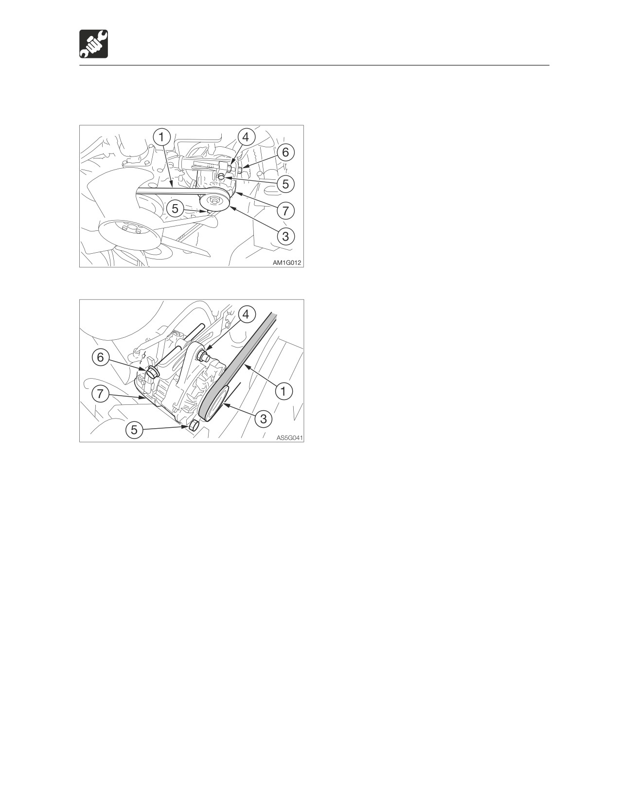
<TB285>
<TB290>
1. Loosen the bolt (5) and locking nut (4).
2. Turn the adjustment bolt (6) to move the
alternator (7) and to adjust the tension of
the fan belt (1).
· Tighten: Clockwise
· Loosen: Counterclockwise
3. Tighten the bolt (5) and locking nut (4).
Tightening torque:
<TB290>
· Locking nut (4) 25 N·m (18.1 ft-lb.)
· Bolt (5) 51N·m (37.6 ft-lb.)
Note: When replacing with a new belt, run
the engine at low idle speed for about 3 to 5
minutes to break in the new belt, before
adjusting the tension.
5-25
Maintenance
After the initial 50 hours (only for new machines)
Inspecting and adjusting the
<TB290>
compressor belt (AC)
Warning
• Stop the engine and allow the machine
to cool down before performing
maintenance.
· The engine, muffler, radiator, hydraulic
lines, sliding parts and many other
parts of the machine are hot
immediately after the engine is
stopped. Touching these parts will
cause burns.
• The high-pressure pipes of the air
Inspection
conditioner can be very hot (80 to 120°C
<TB285>
or 176 to 248°F). Be careful not to burn
yourself.
IMPORTANT: Do not let any oil or grease
get on the belt. It will cause the belt to
slip, decrease the cooling capacity or
shorten the service life of the air
conditioner.
If the belt is too slack, it will slip and vibrate,
resulting in decreased cooling capacity. The
service life of the air conditioner also will be
shortened. Adjust the belt tension to the
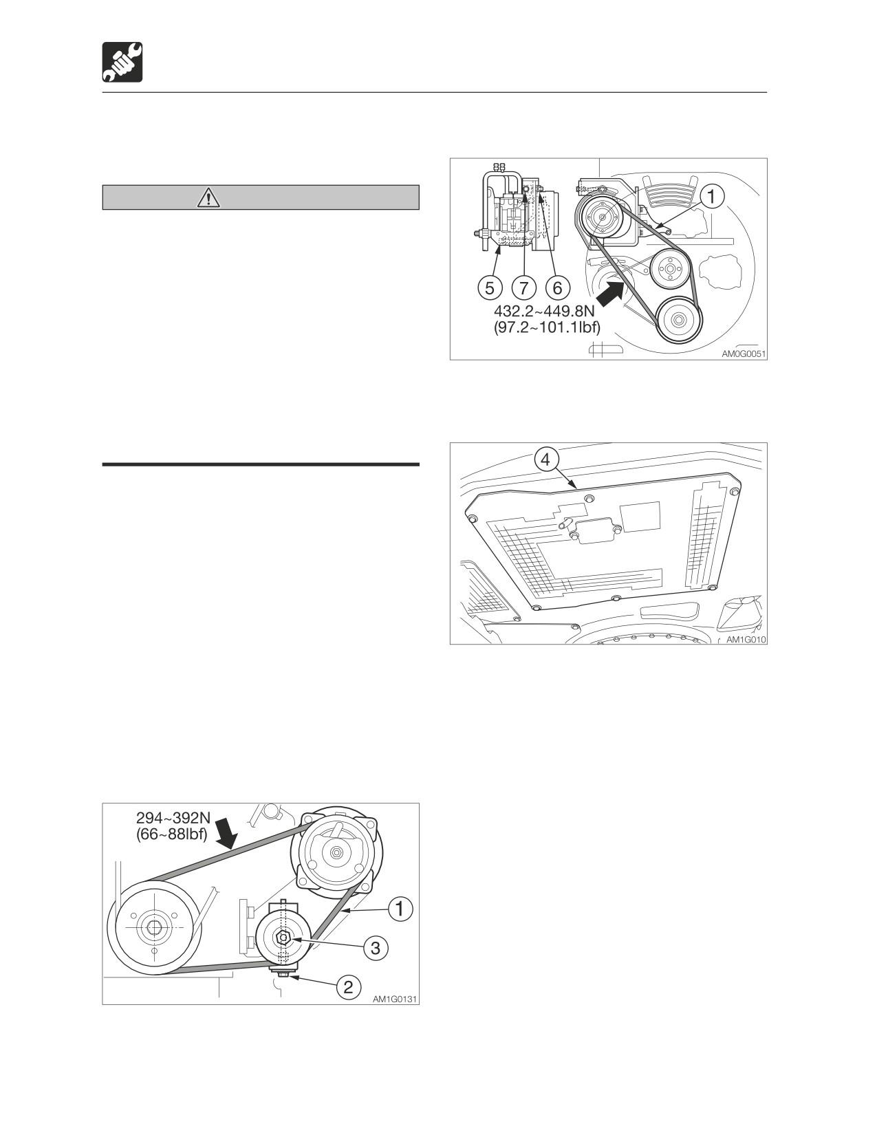
1. Loosen the bolts and remove the under
standard value.
cover (4). <TB285>
For TB285, 294 to 392 N or 66 to 88 lbf.
1. Open the engine hood. <TB290>
For TB290, 432.2 to 449.8 N or 97.2 to
2. Measure the belt (1) tension using the belt
101.1 lbf
tension gauge. The belt tension is normal
if the belt tension gauge indicates the
<TB285>
following values.
For TB285, 294 to 392 N or 66 to 88 lbf.
For TB290, 432.2 to 449.8 N or 97.2 to
101.1 lbf
5-26
Maintenance
After the initial 50 hours (only for new machines)
Adjustment
<TB285>
If the belt tension is not normal, adjust it with
the adjuster bolt (2).
1. Loosen the locking nut (3).
2. Turn the adjuster bolt (2) as follows.
· Tighten: Clockwise
· Loosen: Counterclockwise
3. Tighten the locking nut (3) after
adjustment.
Tightening torque:
· Locking nut (4) 31.4 to 45.1 N·m (23.2
to 33.3 ft-lb.)
<TB290>
If the belt tension is not normal, tilt the
compressor to adjust the tension.
1. Loosen the fixing bolt (5) and fixing nut (6).
2. Turn the adjuster bolt (7) as follows.
· Tighten: Clockwise
· Loosen: Counterclockwise
3. Tighten the fixing bolt (5) and fixing nut (6)
upon completion of adjustment.
Note: When replacing with a new belt, run
the engine at low idle speed for about 3 to 5
minutes to break in the new belt, before
adjusting the tension again.
Replacing
Replace the belt in the following cases:
· There are cuts or cracks.
· The belt is worn and touches the bottom of
the V groove in the pulley.
· The belt stretched too loose to be
adjusted.
5-27
Maintenance
Every 50 hours
Every 50 hours
Inspecting the crawler belt
tension
Note: This machine uses a hydraulic cylinder
to adjust the tension of the crawler belts. It is
not necessary to regularly perform
adjustments of the crawler belt tension.
If the tension is too loose and the track
comes off, the hydraulic cylinder is likely
faulty. Ask your sales or service dealer for
repairs.
5-28
Maintenance
Every 50 hours
Lubricating the slew bearing
4. Lower the bucket to the ground, and then
stop the engine.
5. Repeat the steps 2 to 4 above three
Warning
times.
Do not slew while lubricating. Doing so is
6. Wipe off the grease expelled from the slew
dangerous, as you may get caught in the
bearing and grease fitting.
machine.
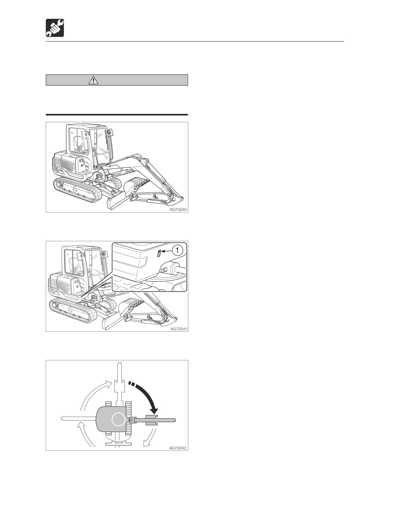
1. Stop the engine with the machine in the
posture shown on the figure above.
2. Use the grease gun to grease the grease
fitting (1).
3. Start the engine, lift the bucket and slew
clockwise 90°.
5-30
Maintenance
Every 50 hours
Draining the water from the fuel
Bleeding air from the fuel system
tank
Refer to “Bleeding air from the fuel system”
on page 6-8.
Warning
Note: Air in the fuel system causes the
• Do not smoke or permit open flames
engine to fail to start or to have problems.
while handling fuel or working on the
Bleed air when the fuel tank is emptied,
fuel system.
using the same procedure above.
• Never remove the fuel cap or add fuel
when the engine is running or still hot.
Do not spill fuel on the hot surface of
the machine.
• Fill the fuel tank in a well ventilated
place.
• Do not fill the fuel tank to capacity.
Allow room for oil expansion.
• Clean up spilled fuel immediately.
• Securely tighten the fuel filler cap.
• Use the correct grade of fuel for the
operating season.
Do the draining operation before starting the
machine.
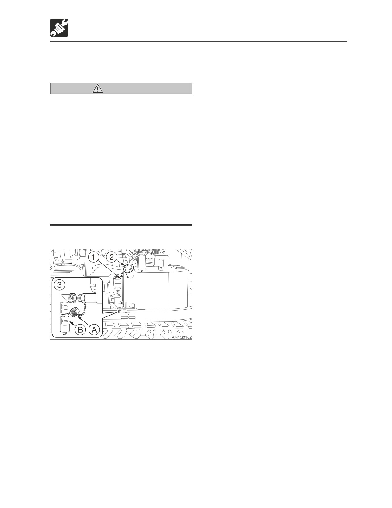
1. Open the side cover.
2. Remove the fuel filler cap (2).
3. Place a pan under the drain valve (3).
4. Remove the cap (A), install the connector
(B), and then drain the water and sediment
buildup in the bottom of the tank (the
water comes out when the screw is
tightened).
5. Remove the connector (B) and install the
cap (A).
6. Add fuel while watching the sight gauge
(1).
7. Tighten the fuel filler cap (2).
8. Close the side cover and lock it with the
key.
9. Bleed air.
5-31
Maintenance
Every 50 hours
Inspecting the battery fluid level
Inspection
and replenishing
IMPORTANT: Check the fluid level of all
cells following the steps below, even
Danger
when the fluid level can be checked using
• Do not use the battery when the fluid
the indicator.
level is below the lower level limit. Doing
so will hasten the deterioration of the
1. Open the engine hood.
internal portions of the battery and
shorten the battery life. It also can
cause rupturing (explosion).
• Batteries generate flammable hydrogen
gas which may explode. Keep away
from flame, sparks, fire or lighted
cigarettes.
• Use a dampened cloth to clean above
the fluid level line and check the fluid
level. Do not clean with a dry cloth;
otherwise it can cause static electricity
to build up, resulting in ignition or
explosion.
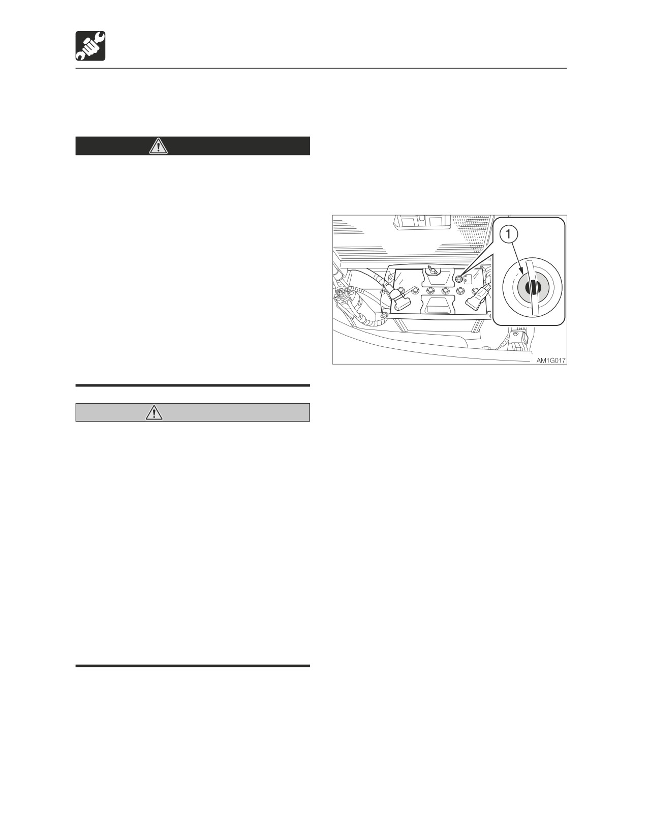
2. Inspect the indicator (1).
· Blue: Good
· White: Charging needed
Warning
· Red: Insufficient battery fluid
• Wear protective goggle and clothing
3. Inspect the fluid level.
when working with batteries.
The fluid level must be between the upper
• Do not add the distilled water above the
level line (H) and lower level line (L). If not,
upper level limit. Doing so could cause
add distilled water up to the line (H).
the fluid to leak. This fluid can cause
skin damage if contacted, or can cause
the machine components to corrode.
• Batteries contain sulfuric acid which will
damage eyes or skin if contacted.
· If eye contact occurs, flush
immediately with clean water and get
prompt medical attention.
· If accidentally swallowed, drink large
quantities of water or milk and call a
physician immediately.
· If acid contacts skin or clothing, wash
off immediately with a lot of water.
5-32
Maintenance
Every 50 hours
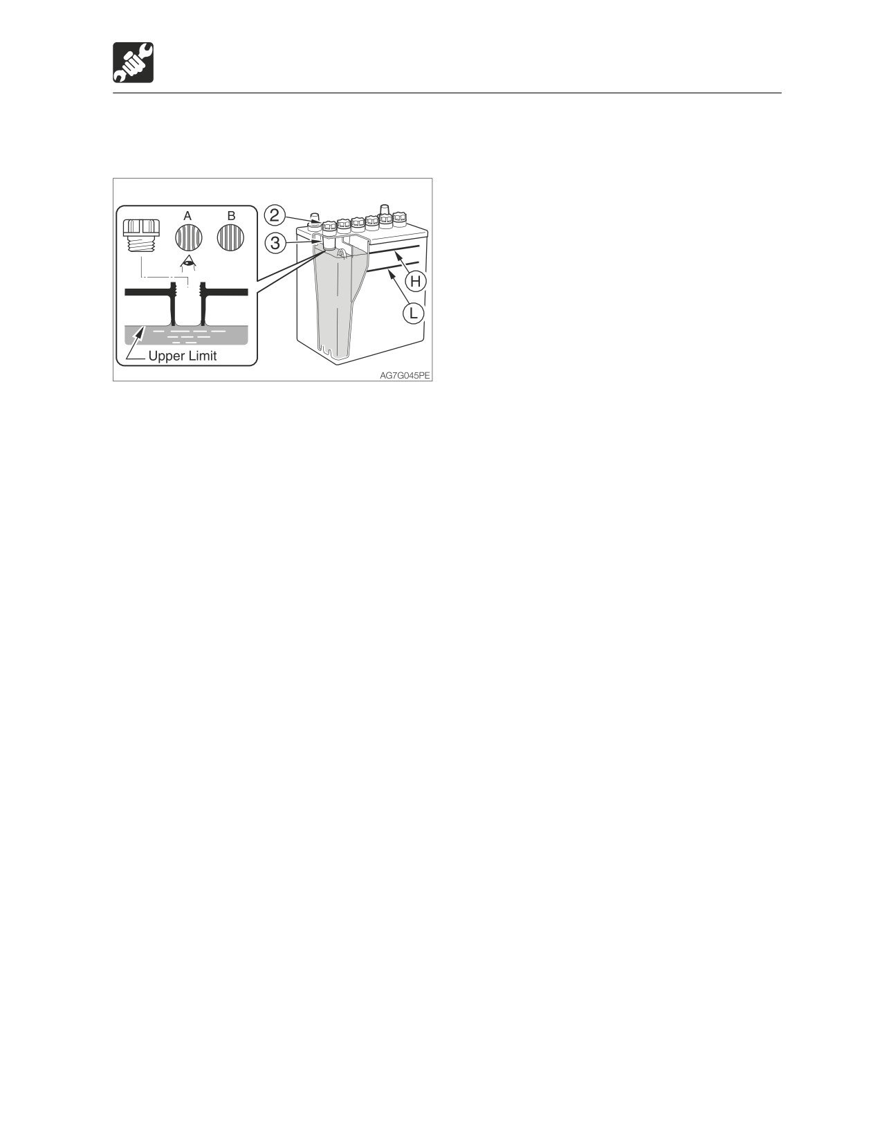
• If the fluid level cannot be checked by fluid
level lines:
Remove the caps (2) and look into the
fluid filler holes to check the fluid level. If
the fluid is below the sleeve (3), be sure to
add distilled water up to the bottom edge
of the sleeve (3).
Proper level (A)
If the fluid reaches up to the bottom edge
of the sleeve (3), the surface tension
causes the fluid to swell and the plate
appears as if it is distorted.
Level too low (B)
If fluid does not reach up to the bottom
edge of the sleeve (3), the plate looks
laminar, not distorted.
4. Check the terminals for looseness and
dirt.
Replenishing
When adding distilled water, do so before
starting operations in order to prevent
freezing.
1. Remove the caps (2), and add distilled
water until the upper level (H).
2. Check that the indicator (1) turns blue.
3. Clean the exhaust hole on the cap, then
tighten the caps (2) securely.
5-33
Maintenance
After the initial 250 hours (only for new machines)
After the initial 250
hours (only for new
machines)
Replacing the hydraulic oil
return filter
Warning
• Stop the engine and allow the machine
to cool down before performing
maintenance.
· The engine and the hydraulic system
and many other parts of the machine
are hot immediately after the engine is
stopped. Touching these parts will
cause burns.
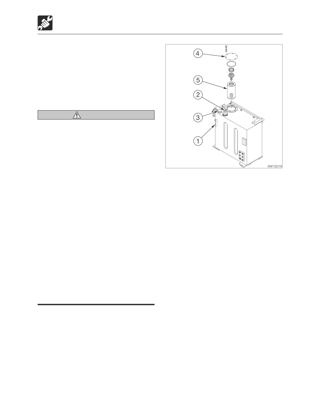
1. Open the side cover.
· The hydraulic oil is also hot and under
2. Press the air breather button (2) to relieve
high pressure.
the internal pressure from the tank.
Be careful not to touch the hydraulic
3. Loosen the bolts and remove the flange
oil when loosening the cap or plug.
(4).
Working on the machine under these
4. Remove the return filter (5).
conditions could result in burns or
5. Install a new return filter.
injuries due to the hot oil spurting out.
6. Install the flange (4) on its original position.
• Oil may spurt out if caps or filters are
7. Inspect the level with the sight gauge (1),
removed or pipes are disconnected
and replenish if the level is too low.
before releasing the pressure in the
Refer to “Inspect the hydraulic oil tank
hydraulic system.
level and replenishing” on page 5-20.
· Press the air breather button to relieve
the internal pressure from the tank.
· When removing plugs or screws, or
when disconnecting hoses, stand to
the side and loosen them slowly to
gradually release the internal pressure
before removing.
5-34
Maintenance
After the initial 250 hours (only for new machines)
Replacing the pilot line filter
Warning
• Stop the engine and allow each part of
the machine to cool down before
performing maintenance.
· The engine, the hydraulic system and
many other parts of the machine are
hot immediately after the engine is
stopped. Touching these parts will
cause burns.
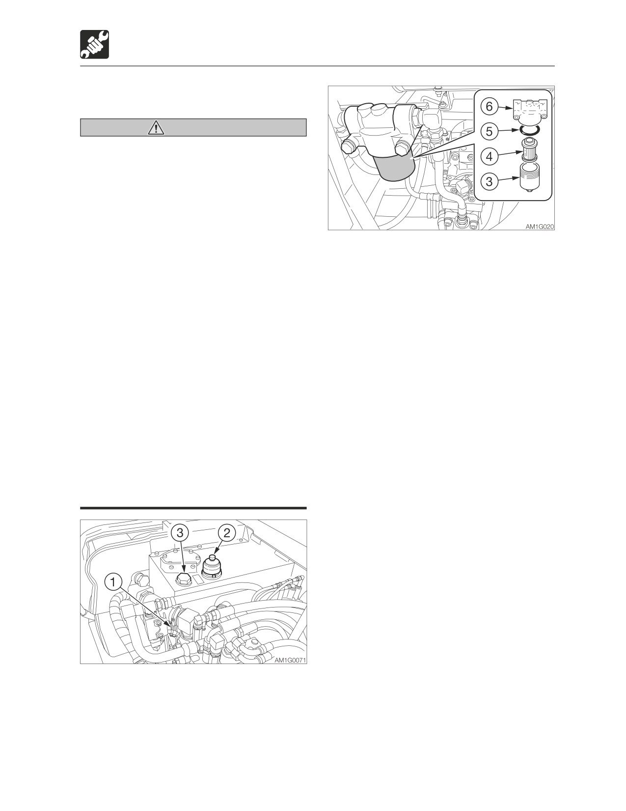
3. Open the engine hood.
· The hydraulic oil is also hot and under
4. Turn the case (3) counterclockwise and
high pressure immediately after the
remove it.
engine is stopped.
5. Remove the element (4) and O-ring (5).
Be careful not to touch the oil when
6. Clean the inside of the case (3).
loosening the cap or plug. Working on
7. Apply a thin layer of oil on the O-ring of the
the machine under these conditions
new filter.
could result in burns or injuries due to
8. Install the new element on the filter stand
the hot oil spurting out.
(6).
• Oil may spurt out if caps or filters are
9. Apply a thin layer of oil on the new O-ring
removed or pipes are disconnected
(5).
before releasing the pressure in the
10. Install the new O-ring (5) and the case (3)
hydraulic system.
on the filter stand (6).
· Press the air breather button to relieve
11. Inspect the level with the sight gauge (1)
the internal pressure from the tank.
and replenish if the level is too low.
· When removing plugs or screws, or
Refer to “Inspecting the hydraulic oil tank
when disconnecting hoses, stand to
level and replenishing” on page 5-20.
the side and loosen them slowly to
gradually release the internal pressure
before removing.
1. Open the side cover.
2. Press the air breather button (2) to relieve
the internal pressure from the tank.
5-35
Maintenance
After the initial 250 hours (only for new machines)
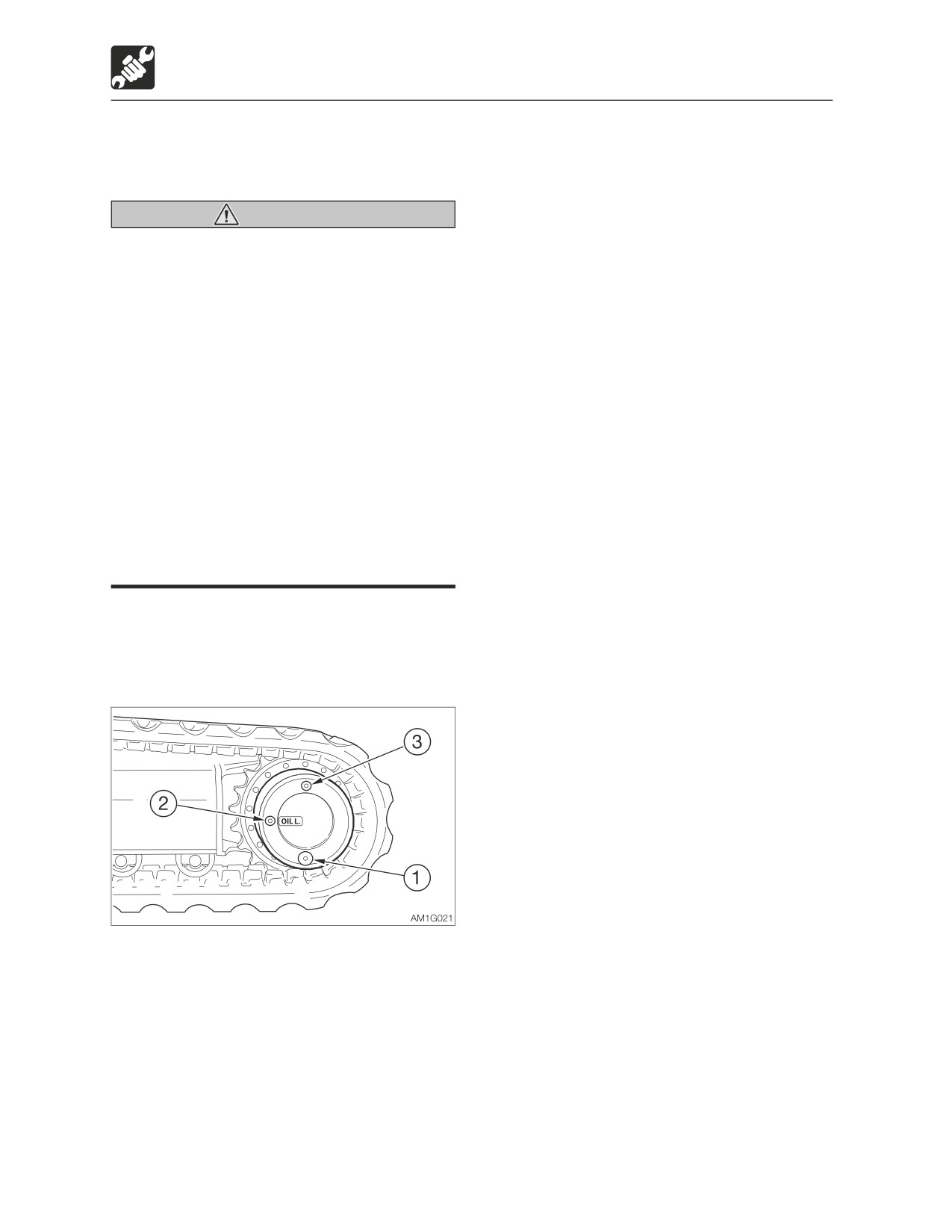
Replacing the travel motor gear
6. Add oil through the hole of the plug (3)
oil
until oil flows out of the hole of the plug
(2).
7. Tighten the plugs (2) and (3).
Warning
·
Tightening torque: 58.8 ± 9.8 N·m (43.4
• Stop the engine and allow the machine
± 7.2 ft-lb.)
to cool down before performing
maintenance.
· The travel motor is hot immediately
after the engine is stopped. Touching
it will cause burns.
· The gear oil is also hot and under high
pressure immediately after the engine
is stopped.
Be careful when loosening the plugs.
Working on the machine under these
conditions could result in burns or
injuries.
• The pressure in the reduction gear case
of travel motor may cause oil or the plug
to fly out. Loosen the plug slowly to
release the pressure.
IMPORTANT: If the percentage of the
traveling time within the total operating
time is high, replace the gear oil earlier
than the specified time.
1. Set the travel motor so that plug (1) is at
the very bottom.
2. Place a pan under the plug (1).
3. Remove the plugs (1), (2) and (3) and drain
the oil.
4. Rewrap the plugs with new sealing tape.
5. Tighten the plug (1).
· Tightening torque: 58.8 ± 9.8 N·m (43.4
± 7.2 ft-lb.)
5-36
Maintenance
Every 250 hours
Every 250 hours
Replacing the engine oil and the
oil filter
Refer to “Replacing the engine oil and the oil
filter” on page 5-22.
Inspecting and adjusting the fan
belt
Refer to “Inspecting and adjusting the fan
belt” on page 5-24.
Inspecting and adjusting the
compressor belt (AC)
Refer to “Inspecting and adjusting the
compressor belt” on page 5-26.
5-37
Maintenance
Every 250 hours
Cleaning the air cleaner
Warning
• Stop the engine and allow the machine
to cool down before performing
maintenance.
· The engine, muffler, radiator and many
other parts of the machine are hot
immediately after the engine is
stopped. Touching it will cause burns.
• Wear required appropriate equipment
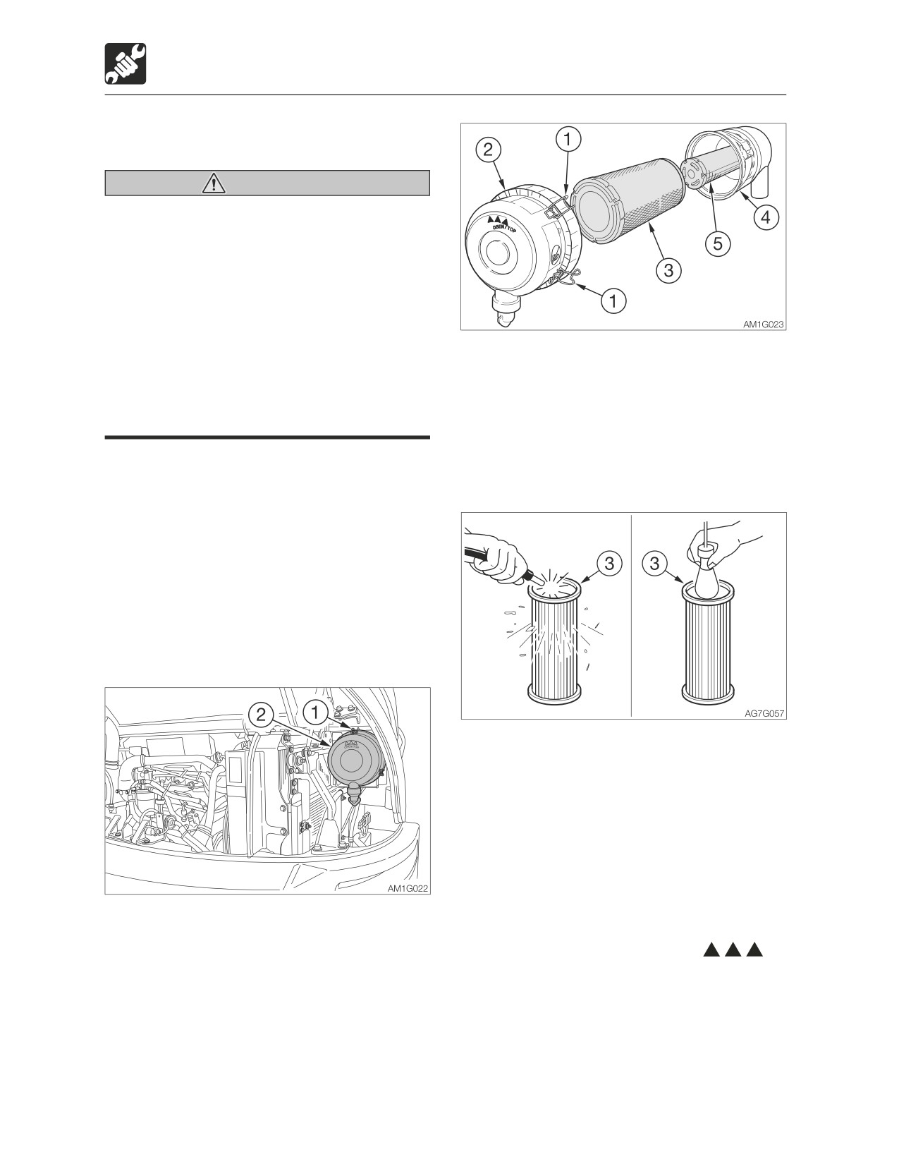
2. Loosen the clamps (1) and remove the
such as protective goggle and filter
dust cup (2).
mask when using compressed air, as
3. Clean the inside of the dust cup (2).
metal fragments or other objects can fly
4. Remove the primary element (3).
and cause serious injury.
To prevent dirt from getting inside the
engine, do not remove the secondary
IMPORTANT: Be careful not to scratch the
element (5).
element. Do not use an element if it is
5. Clean the inside of the body (4).
damaged.
IMPORTANT: When operating the
machine in very dusty places, perform
inspection and maintenance operations
every day.
IMPORTANT: Be sure to install the
element and dust cap securely. If not,
dust could be drawn into the cylinder,
damaging the engine.
6. Clean the primary element (3) with dried
compressed air (294 to 490 kPa or 43 to
71 psi).
First blow the air from the inside of the
element along the pleats. Then blow the
air from the outside and finally from the
inside again.
7. Light up the inside of the primary element
(3) with a light bulb, inspect it, and replace
1. Open the engine hood.
it if there are small holes or thin spots.
8. Install the primary element (3).
9. Install the dust cup (2) with its “
OBEN/TOP” mark facing up, and then
fasten it with the clamps (1).
5-38
Maintenance
Every 250 hours
Cleaning the radiator fins and oil
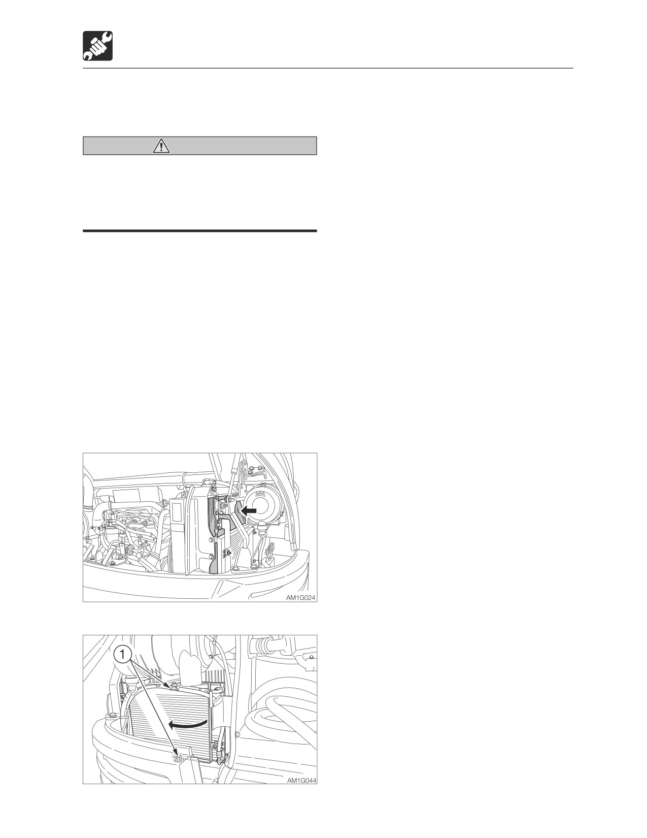
2. Remove the screws (1) and open the
cooler fins
condenser.
3. Blow compressed air on the fins to
remove mud and dirt stuck on them.
Warning
Wear required appropriate equipment
such as protective goggle and filter mask
when using compressed air, as metal
fragments or other objects can fly and
cause serious injury.
IMPORTANT: Be careful not to damage
the fins when cleaning.
• When using compressed air or
pressurized water, make sure the
pressure is no higher than 200 kPa (28
psi) and hold the nozzle sufficiently
away from the fins.
IMPORTANT: When using water, cover the
electrical system to prevent water from
getting in.
IMPORTANT: When operating the
machine in very dusty places, perform
inspection and maintenance operations
every day.
1. Open the engine hood.
5-39
Maintenance
Every 250 hours
Cleaning the air filters (air
Cleaning
conditioner)
1. Blow dry, compressed air (138 kPa or 20
psi or less) directly on the filters from the
inside, moving up and down along the
Warning
pleats.
Wear required appropriate equipment
Be sure to keep the nozzle at an adequate
such as protective goggle and filter mask
distance from the filters.
when using compressed air, as metal
2. Wash the filter with neutral detergent if it is
fragments or other objects can fly and
very dirty. Dry the filter completely after
cause serious injury.
washing it.
Clean the filters immediately after operating
in dusty places.
If the filters are clogged, the air flow is
reduced and a booming sound is heard from
the air conditioner unit.
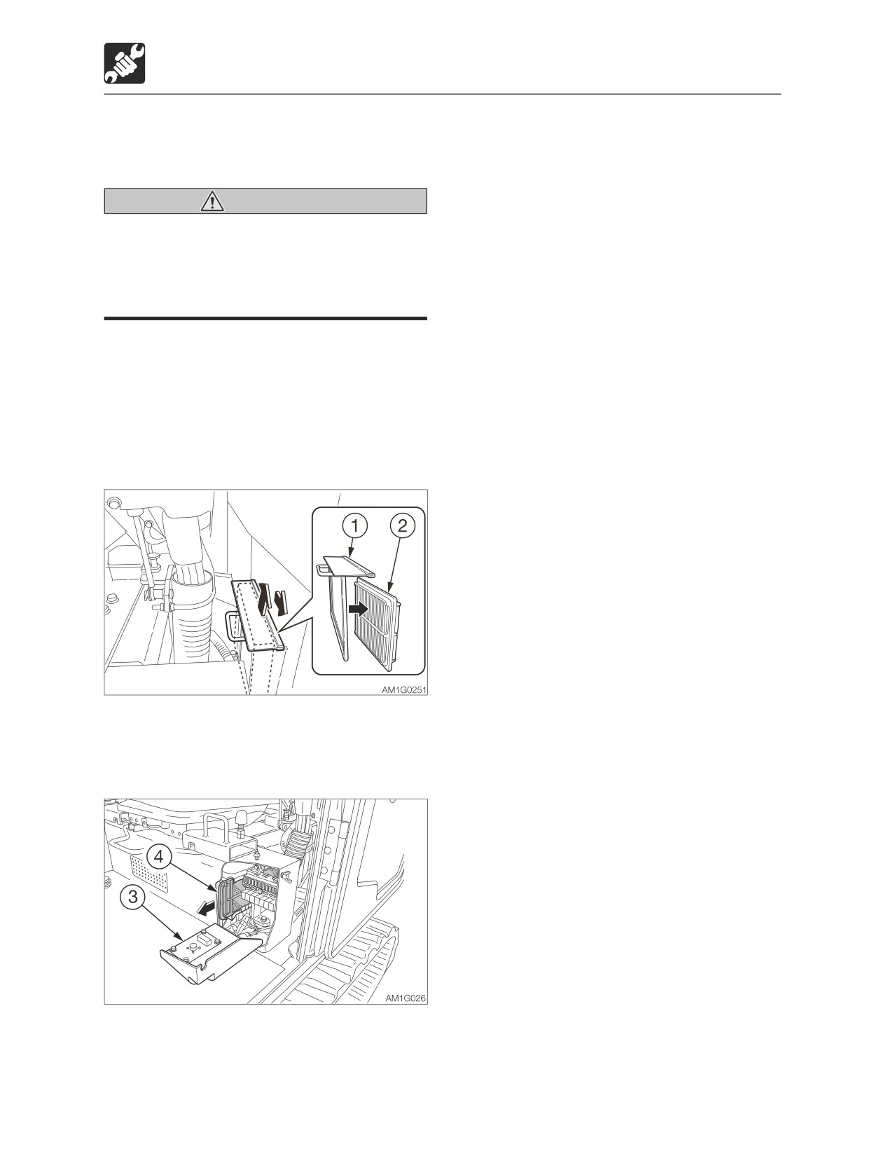
Removing the filters
1. Open the cab door.
2. Pull out the filter case (1) upward and
remove the ventilation filter (2) from the
filter case (1).
3. Open the cover (3).
4. Remove the circulation filter (4).
5. Use compressed air or water to clean the
filters, depending on how dirty they are.
5-40
Maintenance
Every 250 hours
Cleaning the condenser (AC)
Warning
Wear required appropriate equipment
such as protective goggle and filter mask
when using compressed air, as metal
fragments or other objects can fly and
cause serious injury.
IMPORTANT: Be careful not to damage
the fins when cleaning.
• When using compressed air or
pressurized water, make sure the
pressure is no higher than 200kPa (28
psi) and hold the nozzle sufficiently
away from the fins.
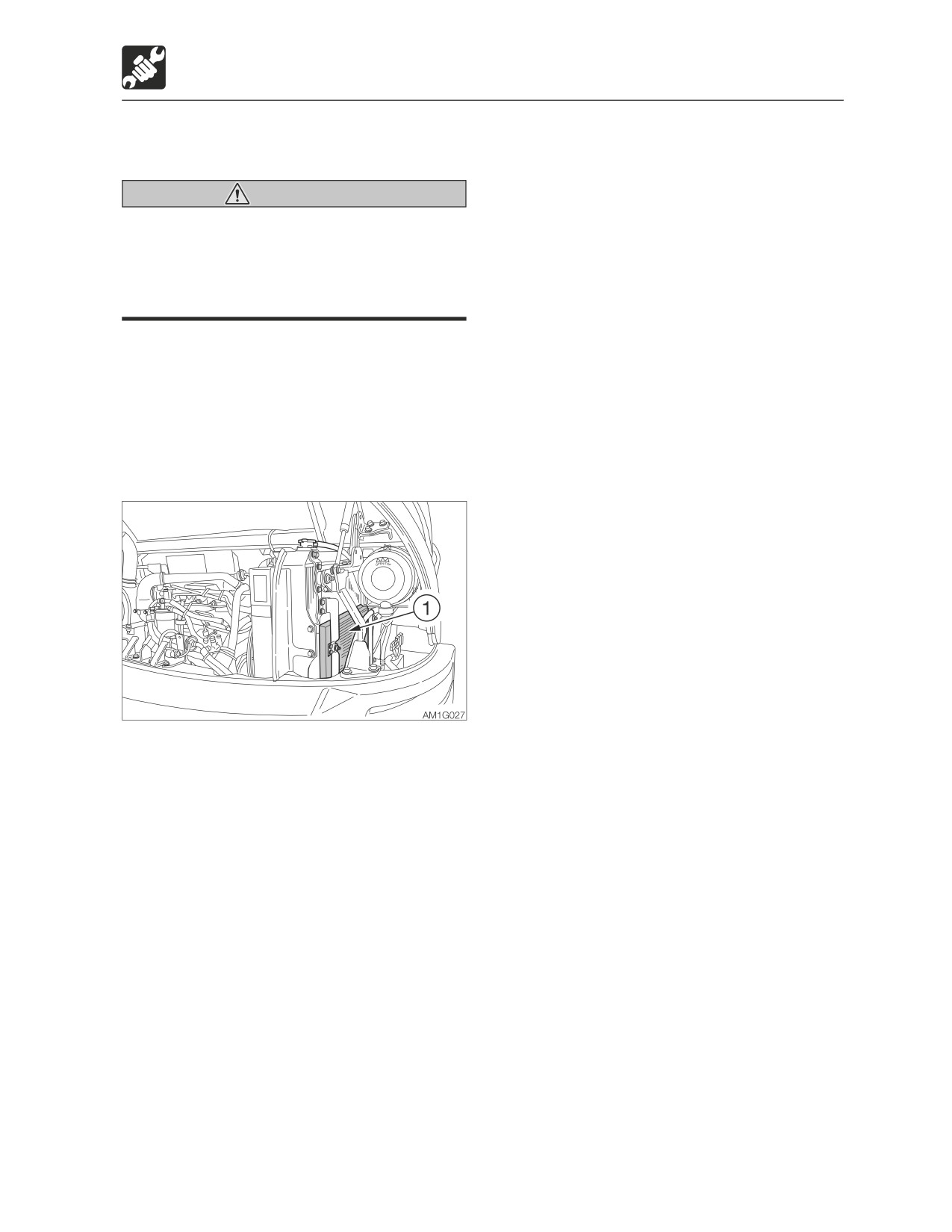
1. Open the engine hood.
2. Clean the condenser (1).
5-41
Maintenance
Every 250 hours
Inspecting the refrigerant (gas)
3. Inspect the refrigerant by watching the
level (AC)
flow of air bubbles through the sight glass
(2).
Refer to “Check list for refrigerant volume”
Warning
on page 5-43.
• Exposure of the eyes or hands to the
cooler’s refrigerant could result in
<TB285>
blindness or frostbite.
Never touch the refrigerant or loosen
the parts of the cooling circuit.
• Keep flames away if the refrigerant gas
is leaking.
• The high-pressure pipes of the air
conditioner can be very hot (80 to 120°C
or 176 to 248°F). Be careful not to burn
yourself.
The cooling capacity decreases if the
amount of refrigerant is insufficient.
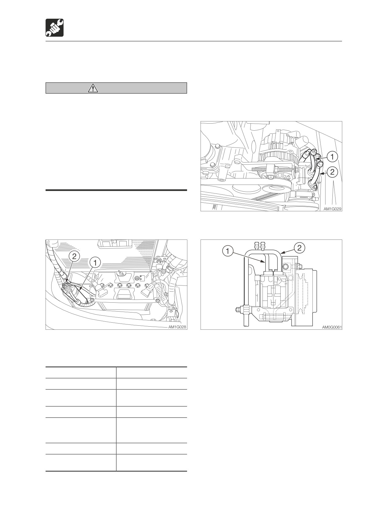
Inspect the refrigerant level using the sight
glass (2) on the top of the receiver drier (1).
<TB290>
1. Open the engine hood.
4. Check the temperature of the
2. Inspect the places for the conditions
compressor’s high pressure pipe (1) and
below.
low pressure pipe (2).
Refer to “Check list for refrigerant volume”
on page 5-43.
Places for inspection
Conditions
Cab door
Fully open
Temperature control
Set fully to the COOL
dial
side
Fan speed
High
Ventilation /
Circulation select
Circulation
switch
Engine speed
Maximum speed
Air conditioner
ON
switch
5-42
Maintenance
Every 250 hours
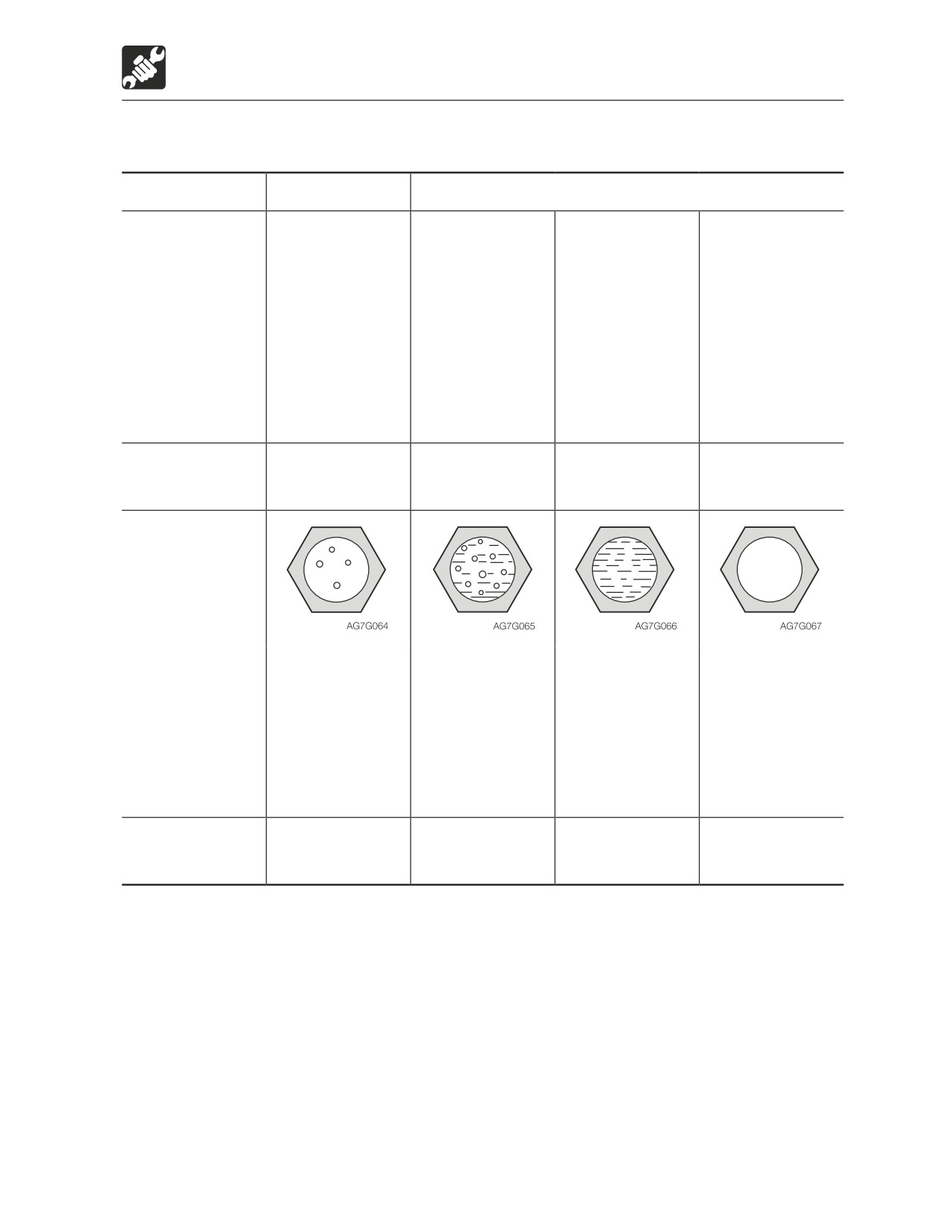
Check list for refrigerant volume
Air conditioner
Normal
Abnormal
High/low
High pressure
High pressure
Little difference in
High pressure
pressure pipe
pipe is hot (80 to
pipe is warm, low
temperature
pipe is hot, low
temperature
120°C or 176 to
pressure pipe is
between the
pressure pipe is
248°F), low
slightly cool. No
high-pressure
slightly cool. A
pressure pipe is
significant
pipe and the low-
significant
cold (8 to 15°C
difference in
pressure pipe.
difference in
or 46 to 59°F).
temperature
temperature
Clear difference
between the
between the
in temperature
pipes.
pipes.
between the
pipes.
Pipe connection
Normal
Some places are
Some places are
Normal
dirty with oil.
extremely dirty
with oil.
Sight glass
Almost
Flow of bubbles
Mist-like flow is
No bubbles is
transparent with
can be seen
faintly visible.
visible, even
some bubbles.
constantly.
when the fan is
Fully transparent
Sometimes
set to High and
when the engine
transparent or
the engine is
speed is
white with
idling.
increased or
bubbles.
decreased.
Refrigerant level
Proper level
Refrigerant may
Refrigerant has
Refrigerant level
be leaking.
leaked; little is
too high
left.
If the air conditioner is not working
If the air conditioner does not work well, set the fan switch to OFF and contact your sales or
service dealer for inspection and/or repairs.
IMPORTANT: Continued use of the air conditioner when it is not working properly will
damage its various parts.
IMPORTANT: Using the air conditioner when there is no refrigerant will damage the
compressor.
IIMPORTANT: Always consult your sales or service dealer for replacing the refrigerant.
Be sure to use R134a refrigerant (740 to 820 g or 1.72 to 1.81 lb.).
5-43
Maintenance
Every 500 hours
<TB290>
Every 500 hours
Replacing the fuel filter
Warning
• Do not smoke or permit open flames
while handling fuel or working on the
fuel system.
• Stop the engine in a well-ventilated
place and allow it to cool down before
performing maintenance.
• Clean up spilled fuel immediately.
1. Open the side cover.
<TB285>
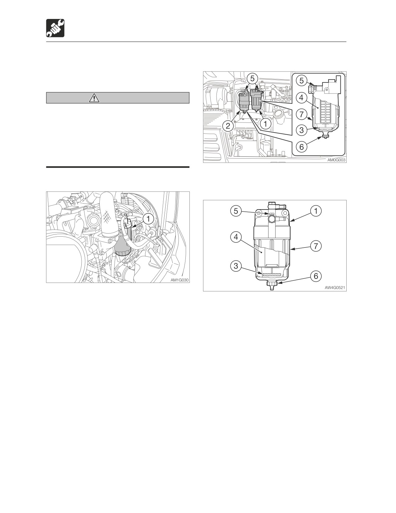
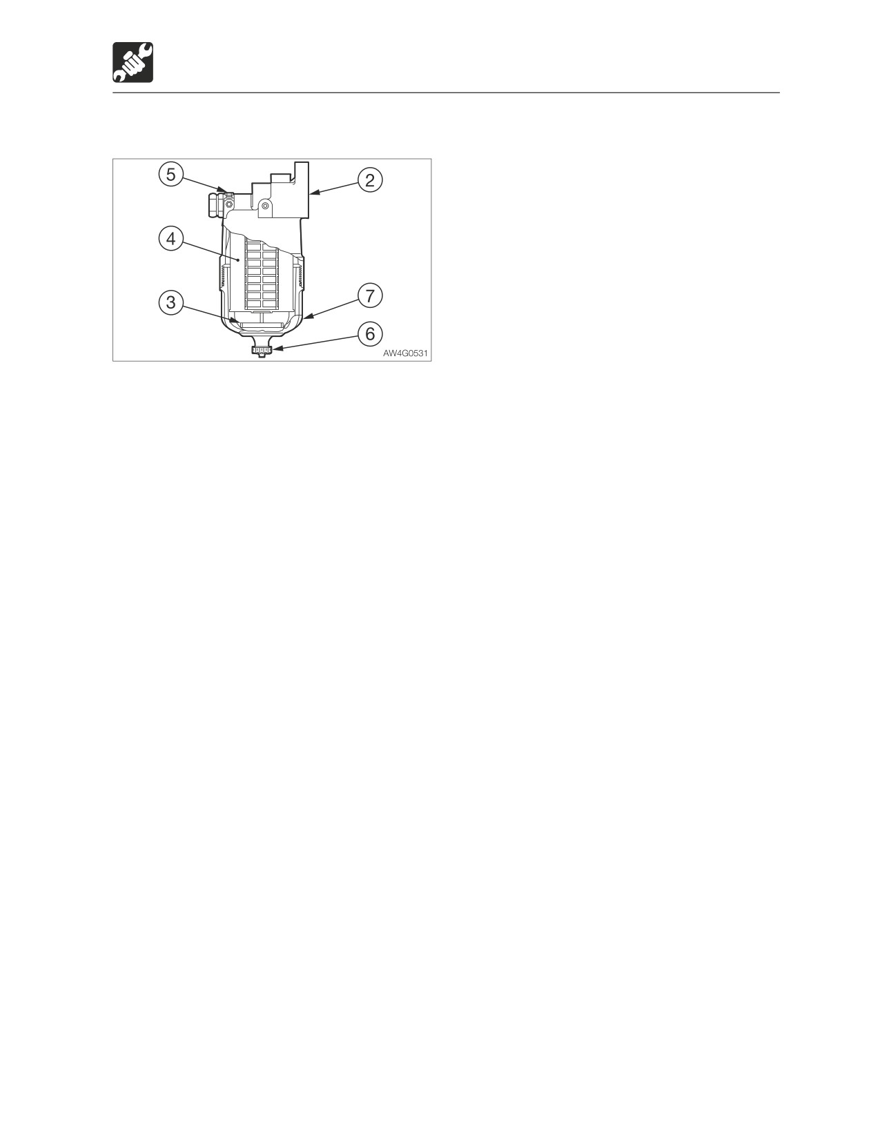
Pre-fuel filter
1. Open the engine hood.
2. Turn the filter (1) counterclockwise with the
2. Place a pan under the pre-fuel filter (1) to
filter wrench and remove it.
catch fuel.
3. Clean the surface of installation of the filter
3. Loosen the vent plug (5) and the drain
stand.
plug (6) to drain the fuel inside.
4. Apply a thin layer of oil on the packing of
4. Remove the case (7) by using a filter
the new filter.
wrench.
5. Install the new filter by hand.
5. Replace the seals with new ones and
6. Tighten one more turn after the filter
lubricate the new seals with diesel fuel.
packing comes in contact with the surface
6. Put the new element (length of 150 mm /
of installation. (Torque when tightening
5.9 in.) (4) in the case (7) and install by
with filter wrench: 19.6 to 23.5 N·m or 14
hand until the seal makes contact with the
to 17ft-lb.)
sealing surface.
7. Bleed the air.
7. Tighten the case (7) with the filter wrench.
Refer to “Bleeding air from the fuel
Tightening torque: 30 N·m (22.1 ft-lb.)
system” on page 6-8.
5-44
Maintenance
Every 500 hours
Main fuel filter
8. Place a pan under the main fuel filter (2) to
catch fuel.
9. Loosen the vent plug (5) and the drain
plug (6) to drain the fuel inside.
10. Remove the case (7) by using a filter
wrench.
11. Replace the seals with new ones and
lubricate the new seals with diesel fuel.
12. Put the new element (length of 131 mm /
5.2 in.) (4) in the case (7) and install by
hand until the seal makes contact with
the sealing surface.
13. Tighten the case (7) with the filter
wrench.
Tightening torque: 29.4 N·m (21.7 ft-lb.)
14. Bleed air.
Refer to “Bleeding air from the fuel
system” on page 6-8.
5-45
Maintenance
Every 500 hours
Replacing the water separator
filter <TB285>
Warning
• Do not smoke or permit open flames
while handling fuel or working on the
fuel system.
• Stop the engine in a well-ventilated
place and allow it to cool down before
performing maintenance.
• Clean up spilled fuel immediately.
1. Open the side cover.
2. Place a pan for catching the waste oil
under the drain hose.
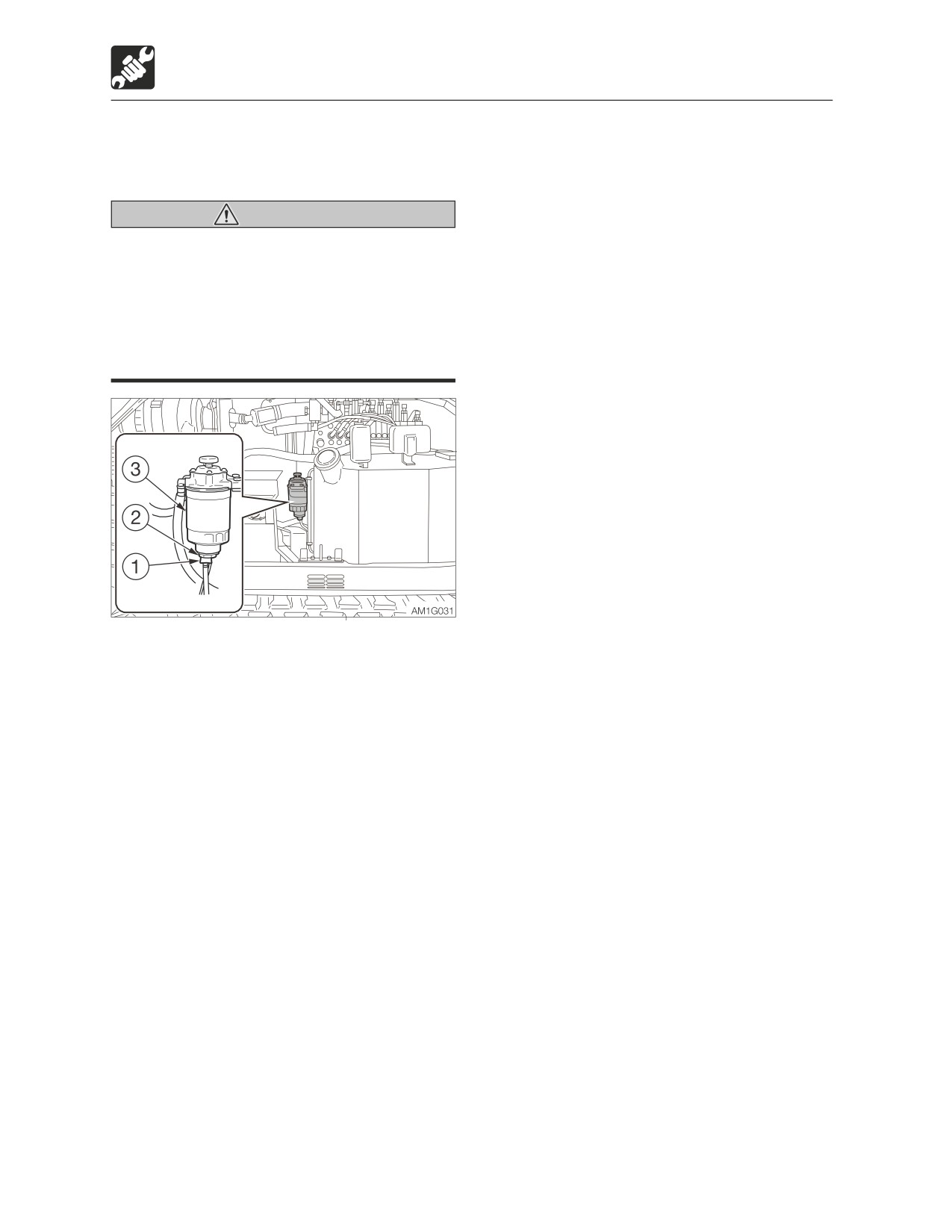
3. Open the drain cock (1) and drain the fuel.
4. Remove the sensor (2).
5. Remove the filter (3).
6. Install the sensor (2) on the new filter.
7. Clean the surface to install the filter stand.
8. Apply a thin layer of oil on the packing of
the new filter.
9. Install the new filter by hand
10. Tighten 2/3 more turn after the filter
packing comes in contact with the
surface of installation.
· Tightening torque: 44.1 N·m (32.5 ft-lb.)
11. Bleed air.
Refer to “Bleeding air from the fuel
system” on page 6-8.
5-46
Maintenance
Every 500 hours
Replacing the feed pump filter
<TB290>
Warning
• Do not smoke or permit open flames
while handling fuel or working on the
fuel system.
• Stop the engine in a well-ventilated
place and allow it to cool down before
performing maintenance.
• Clean up spilled fuel immediately.
1. Open the side cover.
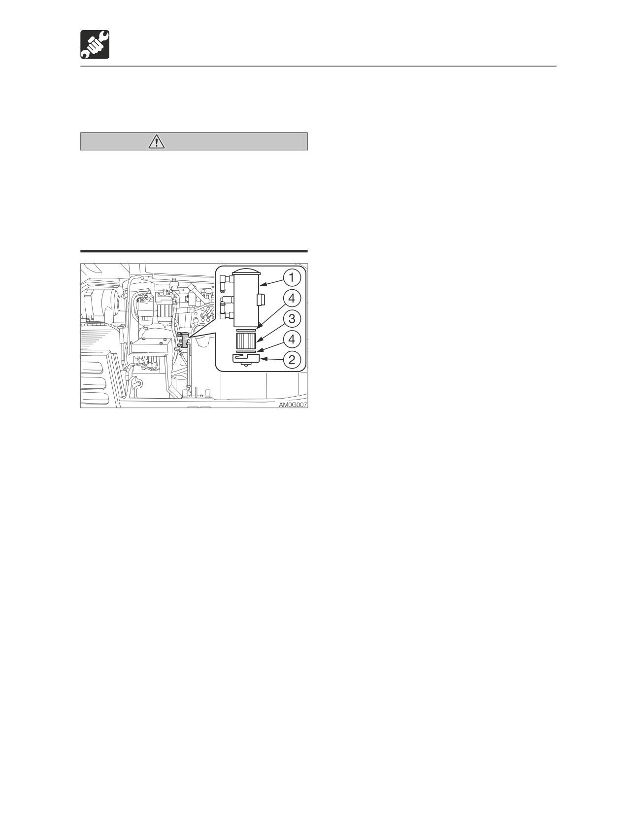
2. Place a pan under the feed pump (1) to
catch fuel.
3. Remove the cover (2).
4. Remove the element (3) and gaskets (4).
5. Install the new element and gaskets.
6. Install the cover (2).
7. Bleed air.
Refer to “Bleeding air from the fuel
system” on page 6-8.
5-47
Maintenance
Every 1000 hours
she must take care not to touch the
Every 1000 hours
lever or pedal unless necessary.
Replacing the hydraulic oil
· The one who performs maintenance
return filter
must make sure to keep his/her body
or clothing away from the moving part
Refer to “Replacing the hydraulic oil return
of the machine.
filter” on page 5-34.
• Standing at the back of the machine
while the engine is running is extremely
dangerous, as the machine could move
Replacing the pilot line filter
suddenly. Never stand at the back of the
machine while the engine is running.
Refer to “Replacing the pilot line filter” on
• Do not remove the radiator cap or the
page 5-35.
drain plug when the cooling water is
hot. Stop the engine and wait until the
engine and the cooling water cool.
Replacing the travel motor gear
Then, slowly loosen the radiator cap
oil
and the drain plug to remove them.
Refer to “Replacing the travel motor gear oil”
When cleaning, if the temperature of the
on page 5-36.
coolant is low, the thermostat will be closed
and the coolant will not circulate in the
radiator. Heat the coolant water to at least
Cleaning the engine cooling
90°C (194°F) before cleaning.
system
1. Open the engine hood and the side cover.
<TB285>
Warning
• Stop the engine and allow the machine
to cool down before performing
maintenance.
· The engine, muffler, radiator and many
other parts of the machine are hot
immediately after the engine is
stopped. Touching these parts will
cause burns.
· The engine coolant is also hot and
under high pressure immediately after
the engine is stopped. Be careful
<TB290>
when loosening the caps or plugs.
Working on the machine under these
conditions could result in burns or
injuries due to the hot coolant spurting
out.
• If maintenance must be performed with
the engine running, always work as a
two person team communicating each
other.
· One person must sit in the operator’s
seat so that he/she can immediately
stop the engine when necessary. He/
5-48
Maintenance
Every 1000 hours
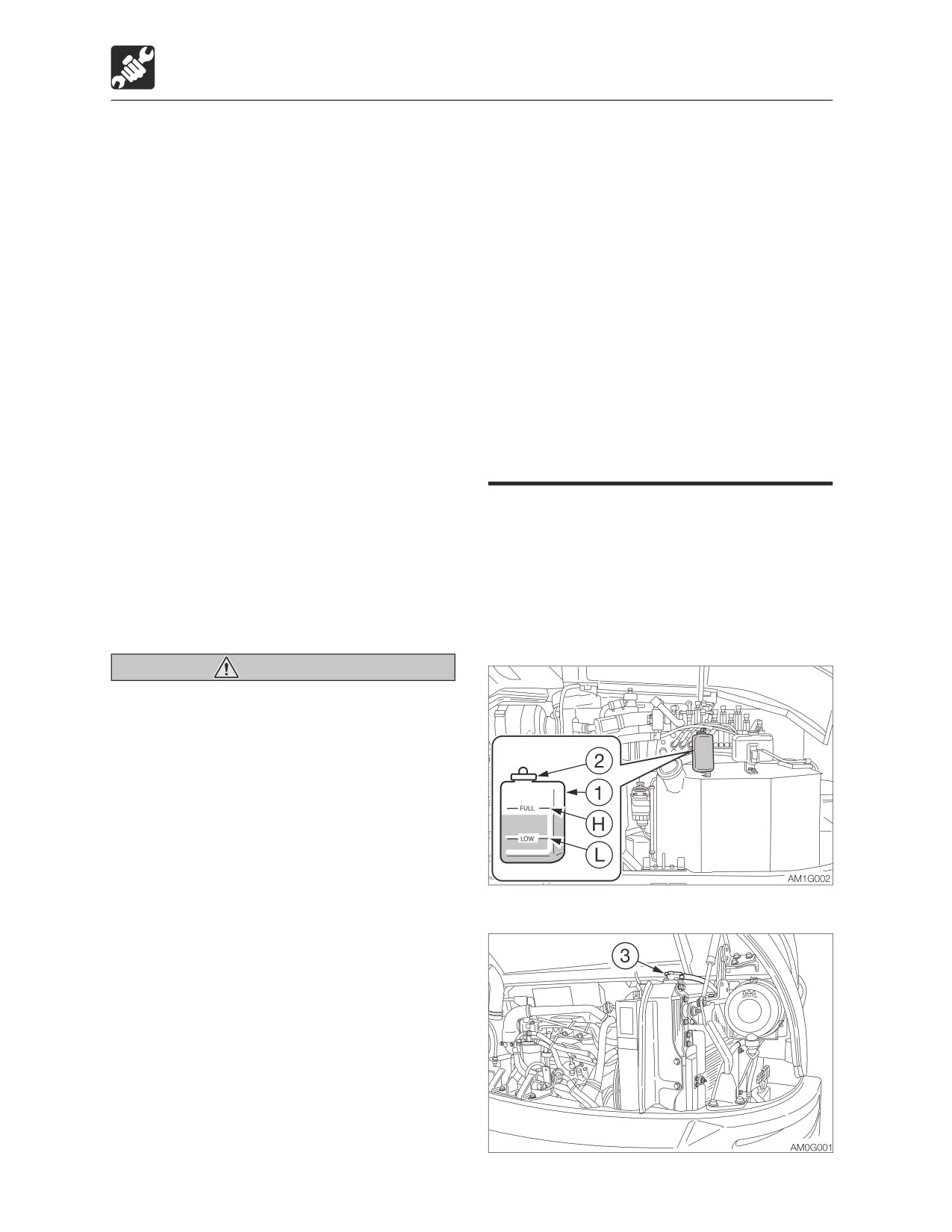
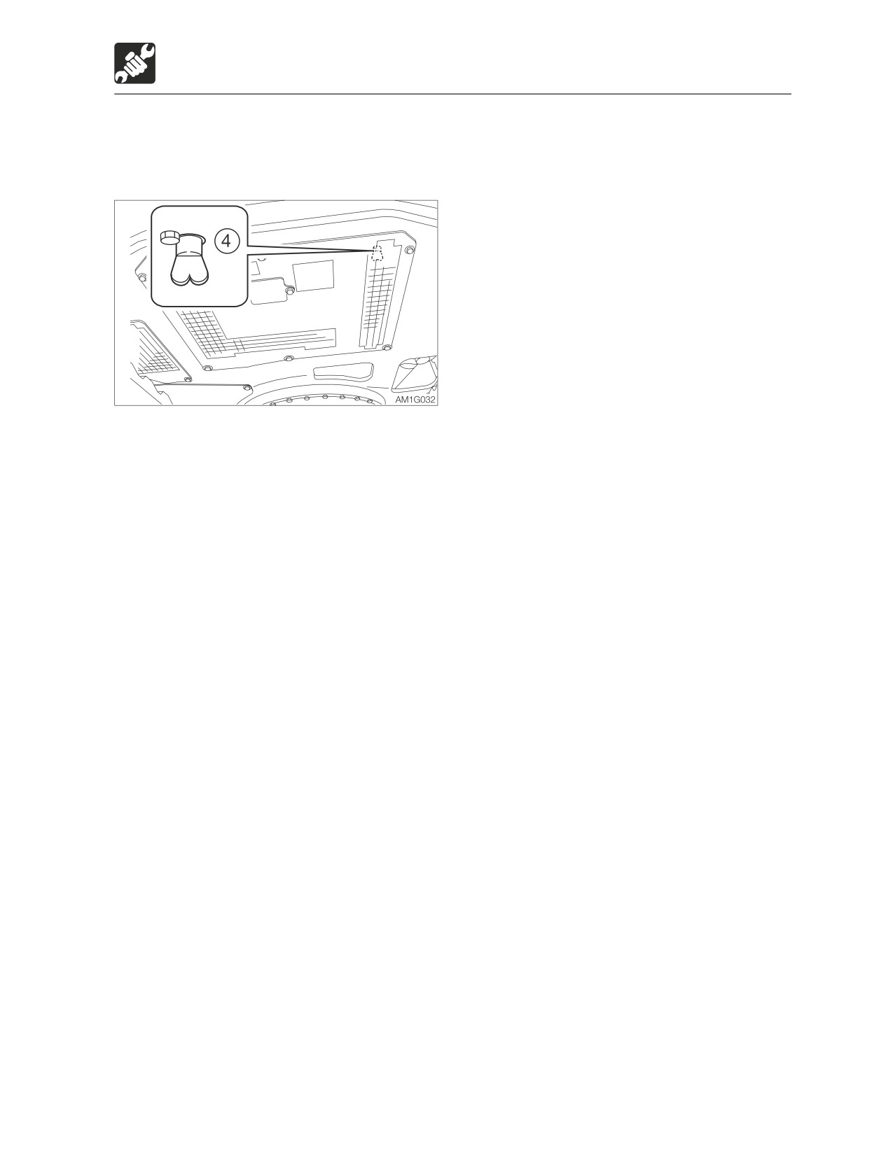
2. Gradually loosen the radiator cap (3) to
15. Increase the water temperature to at
release the internal pressure, and then
least 90°C (194°F). Then, run the engine
remove the cap.
for about 10 minutes with the thermostat
kept open.
16. Stop the engine, wait until the cooling
water temperature becomes lower, and
then check the level of coolant in the
radiator.
If necessary, add cooling water until the
radiator is full.
17. Close the radiator cap (3).
18. Clean the interior of the reserve tank (1),
and then add coolant to the upper limit
(H).
19. When the coolant has been replaced,
3. Place a pan for catching the waste coolant
inspect the coolant level once again after
under the drain plug (4), and then loosen
operating the machine.
the drain plug (4) to drain the coolant.
Once the machine is operated, the
4. Tighten the drain plug (4).
coolant is distributed throughout the
5. Add tap water to the radiator through the
entire system, resulting in the lower
coolant fill port up to the top of the port.
coolant level.
Take time and slowly add water, so that no
Replenish the cooling water that has
air enters the radiator.
been used.
6. Close the radiator cap (3).
7. Start the engine and run it at a speed
slightly above low idling. Raise the water
temperature to at least 90°C (194°F), and
then run the engine for about 10 minutes
with the thermostat open.
8. Stop the engine, wait until the cooling
water temperature becomes lower, and
then remove the drain plug (4) to drain the
water.
9. After draining, clean the cooling system
using a cleaning agent. When using the
cleaning agent, follow the instructions
included with the agent.
10. Repeat the steps 4 to 8 to rinse the
cooling system.
11. Tighten the drain plug (4).
12. Take time and slowly add the new
coolant (mixture of antifreeze and tap
water) to the radiator through the fill port
until it is full.
13. Close the radiator cap (3).
14. Warm up the engine. Use the meters to
check that there are no irregularities in
the cooling system at this time.
5-49
Maintenance
Every 1000 hours
Replacing the air cleaner element
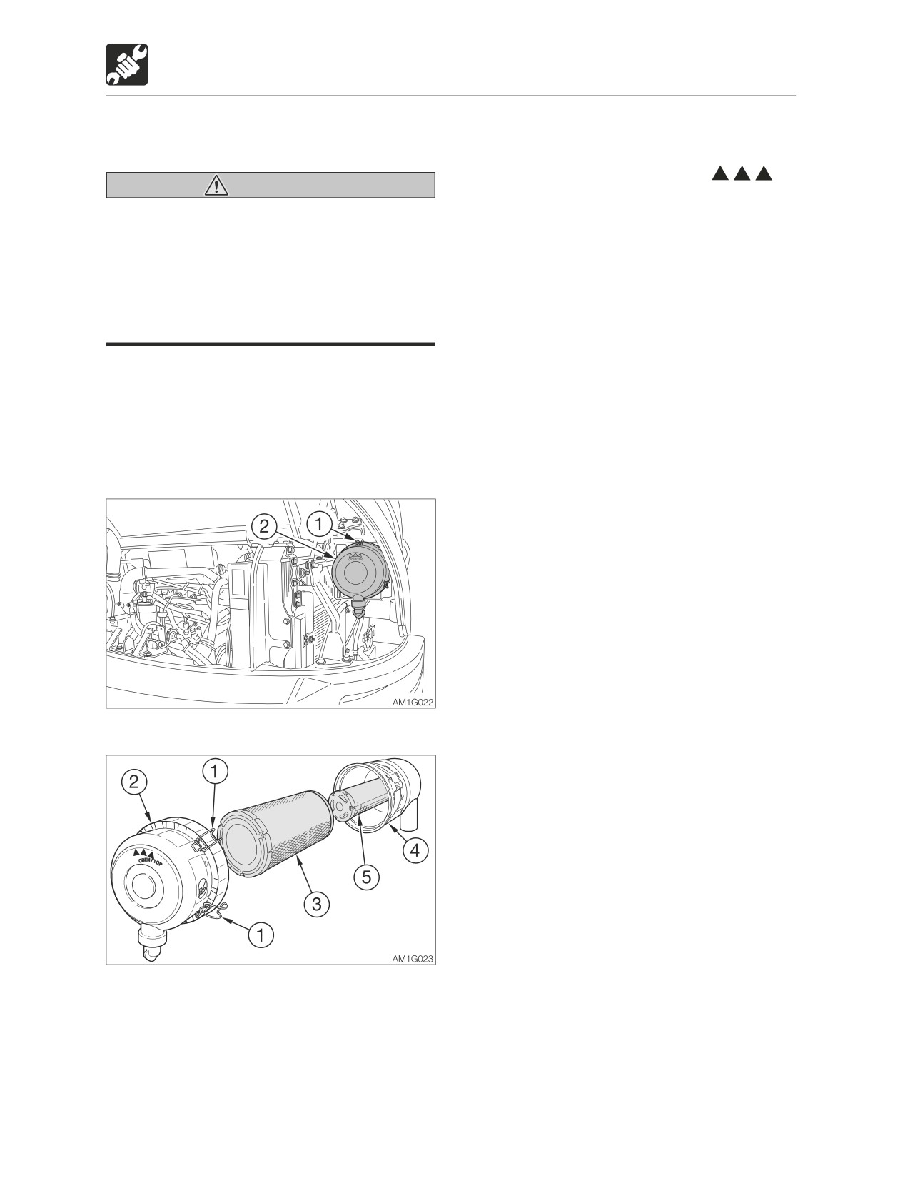
7. Install the new elements. Press them firmly
into the body (4).
8. Install the dust cup (2) with its “
Warning
OBEN/TOP” mark facing up, and then
Stop the engine and allow the machine to
fasten it with the clamps (1).
cool down before performing
maintenance.
• The engine, muffler, radiator and many
other parts of the machine are hot
immediately after the engine is stopped.
Touching these parts will cause burns.
IMPORTANT: Do not use an element if its
pleats, gaskets or seals are damaged.
IMPORTANT: Be sure to install the
element and dust cap securely. If not,
dust could be drain into the cylinder,
damaging the engine.
1. Open the engine hood.
2. Loosen the clamps (1) and remove the
dust cup (2).
3. Clean the inside of the dust cup (2).
4. Remove the primary element (3).
Do not remove the secondary element yet.
5. Clean the inside of the body (4).
6. Remove the secondary element (5).
5-50
Maintenance
Every 1000 hours
Replacing the air breather filter
Inspecting and adjusting the
engine valve clearance
Warning
This operation requires experience. Ask your
Oil may spurt out if caps or filters are
sales or service dealer for it.
removed or pipes are disconnected
before releasing the pressure in the
hydraulic system.
Retightening the engine cylinder
• Press the air breather button to relieve
head bolt <TB285>
the tank pressure.
This operation requires experience. Ask your
sales or service dealer for it.
Inspecting the engine
compression pressure <TB290>
This operation requires experience. Ask your
sales or service dealer for it.
Inspecting and cleaning the
1. Open the side cover.
engine starter and the alternator
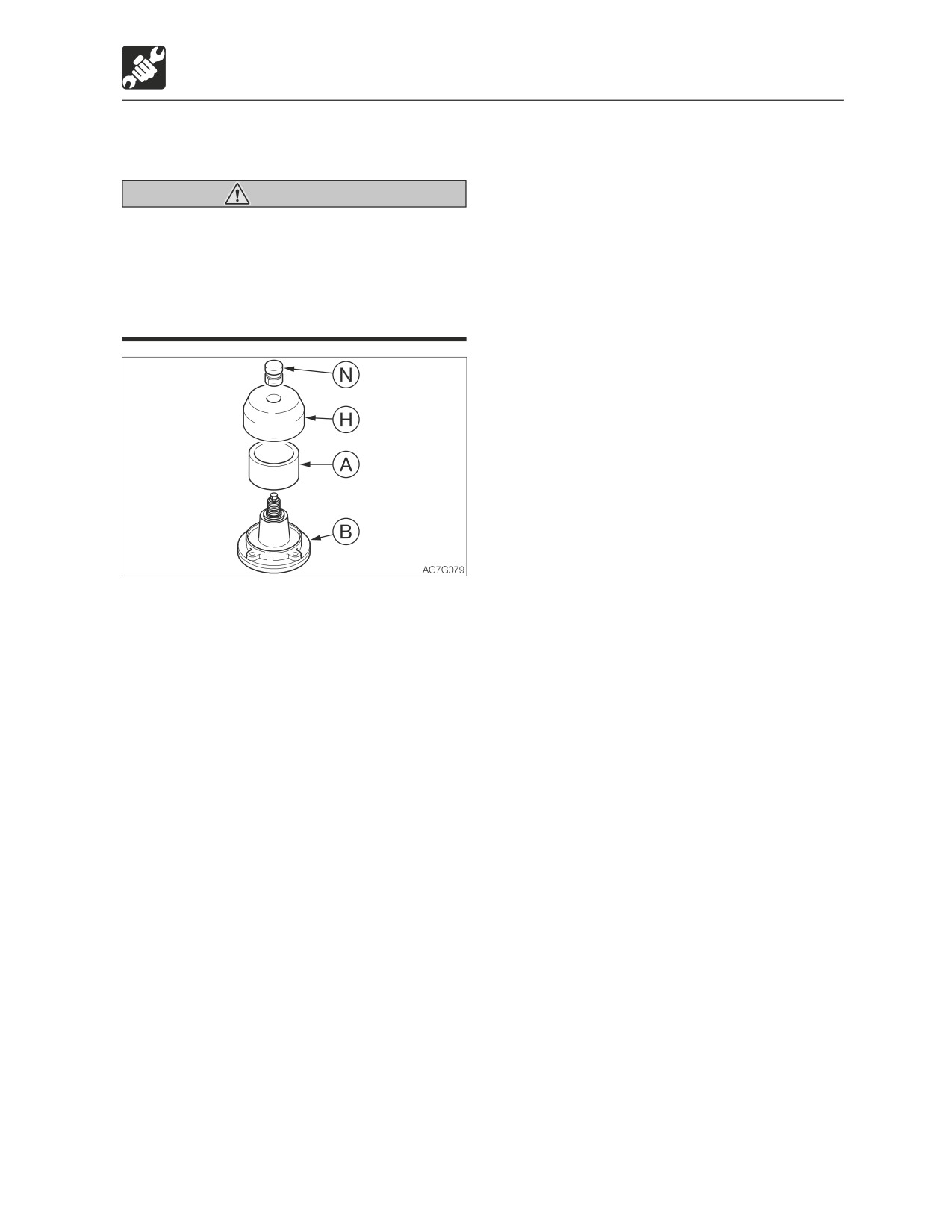
2. Press the button (N) to relieve the internal
<TB290>
pressure from the tank.
3. Loosen the nut and remove the button (N)
This operation requires experience. Ask your
on the air breather.
sales or service dealer for it.
4. Remove the cover (H).
5. Replace the filter (A).
6. Install the cover (H) on the body (B).
7. Install the button (N).
5-51
Maintenance
Every 1500 hours
Every 1500 hours
Inspecting and cleaning the
engine fuel injectors <TB285>
This operation requires experience. Ask your
sales or service dealer for it.
Inspecting the crankcase
breather system <TB285>
This operation requires experience. Ask your
sales or service dealer for it.
5-52
Maintenance
Every 2000 hours
Every 2000 hours
Lapping the engine valve seats
<TB285>
This operation requires experience. Ask your
sales or service dealer for it.
5-53
Maintenance
Every 4000 hours
Every 4000 hours
Replacing the hydraulic oil and
cleaning the suction strainer
Warning
• Stop the engine and allow the machine
to cool down before performing
maintenance.
· The engine and the hydraulic system
and many other parts of the machine
are hot immediately after the engine is
stopped. Touching these parts will
cause burns.
· The hydraulic oil is also hot and under
high pressure immediately after the
engine is stopped.
Be careful when loosening the caps or
plugs. Working on the machine under
these conditions could result in burns
or injuries due to the hot oil spurting
out.
• Oil may spurt out if caps or filters are
removed or pipes are disconnected
before releasing the pressure in the
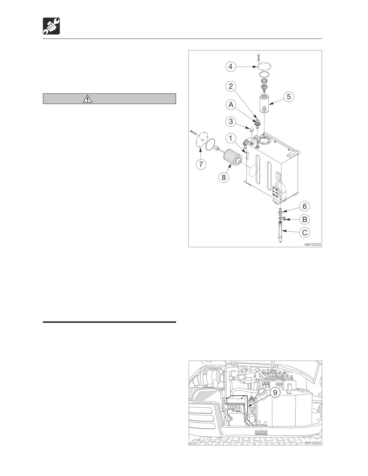
3. Press the button (2) to relieve the internal
hydraulic system.
pressure from the tank.
· Press the air breather button to relieve
4. Replace the air breather filter (A).
the internal pressure from the tank.
Refer to “Replacing the air breather filter”
· When removing plugs or screws, or
on page 5-51.
when disconnecting hoses, stand to
5. Remove the plug (3).
the side and loosen them slowly to
6. Loosen the bolts and remove the flange
gradually release the internal pressure
(4).
before removing.
7. Remove the return filter (5).
8. Place a pan under the plug (6) to catch the
1. Slew 45° clockwise and set the machine
waste oil.
to the hydraulic oil level inspection
9. Remove the cap (B), install connector (C)
posture.
and drain the oil. (The oil comes out when
Refer to “Inspecting the hydraulic oil tank
the screw is tightened.)
level and replenishing” on page 5-20.
2. Open the side cover.
5-54
Maintenance
Every 4000 hours
10. Remove the relay and fuse panel (9).
3. Tighten the drain hose (1) once there are
11. Loosen the bolts and remove the flange
no more air bubbles coming from the
(7).
elbow (2) joint.
12. Remove the suction strainer (8) and
clean it.
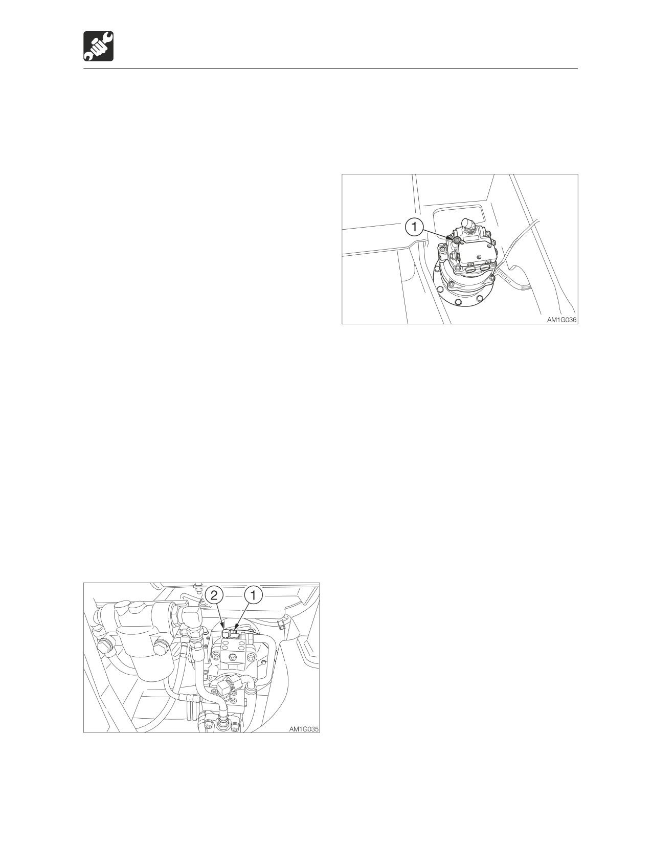
• Slew motor
13. Clean the inside of the hydraulic tank.
14. Remove the connector (C) and install the
cap (B).
15. Install the suction strainer (8) on the tank
and then install the flange (7).
16. Install the new return filter (5) and the
flange (4) on the tank.
17. Add hydraulic oil from the hole of plug (3)
up to the level between the upper limit
(H) and the lower limit (L) in the sight
gauge (1).
18. Tighten the plug (3).
19. Install the relay and fuse panel (9).
1. Loosen the air-bleeding plug (1).
20. Bleed air from the hydraulic oil circuit
2. Tighten the plug (1) once the hydraulic oil
following “Bleeding air” below.
overflows from the air-bleeding plug hole
21. Set the machine to the hydraulic oil level
(1).
inspection posture and inspect the oil
level after the oil cools.
• Cylinders
Refer to “Inspect the hydraulic oil tank
1. Start the engine, let it run at a low-idling
level and replenishing” on page 5-20.
speed for 10 minutes.
2. Maintain the engine at low idle, and then
Bleeding air
slowly extend and retract each cylinder 4
or 5 times, without letting them reach the
IMPORTANT: After replacing the hydraulic
stroke end.
oil, bleed air from the hydraulic circuits
3. While running the engine at high speed,
and hydraulic devices. Failure to do so
slowly extend and retract each cylinder 4
may damage the hydraulic devices.
or 5 times, without letting them reach the
stroke end.
• Hydraulic pump
4. Return the engine speed to low idle, and
then slowly extend and retract each
cylinder 4 or 5 times to the stroke end.
1. Open the engine hood.
2. Loosen the drain hose (1) of the hydraulic
pump.
5-55
Maintenance
Every 4000 hours
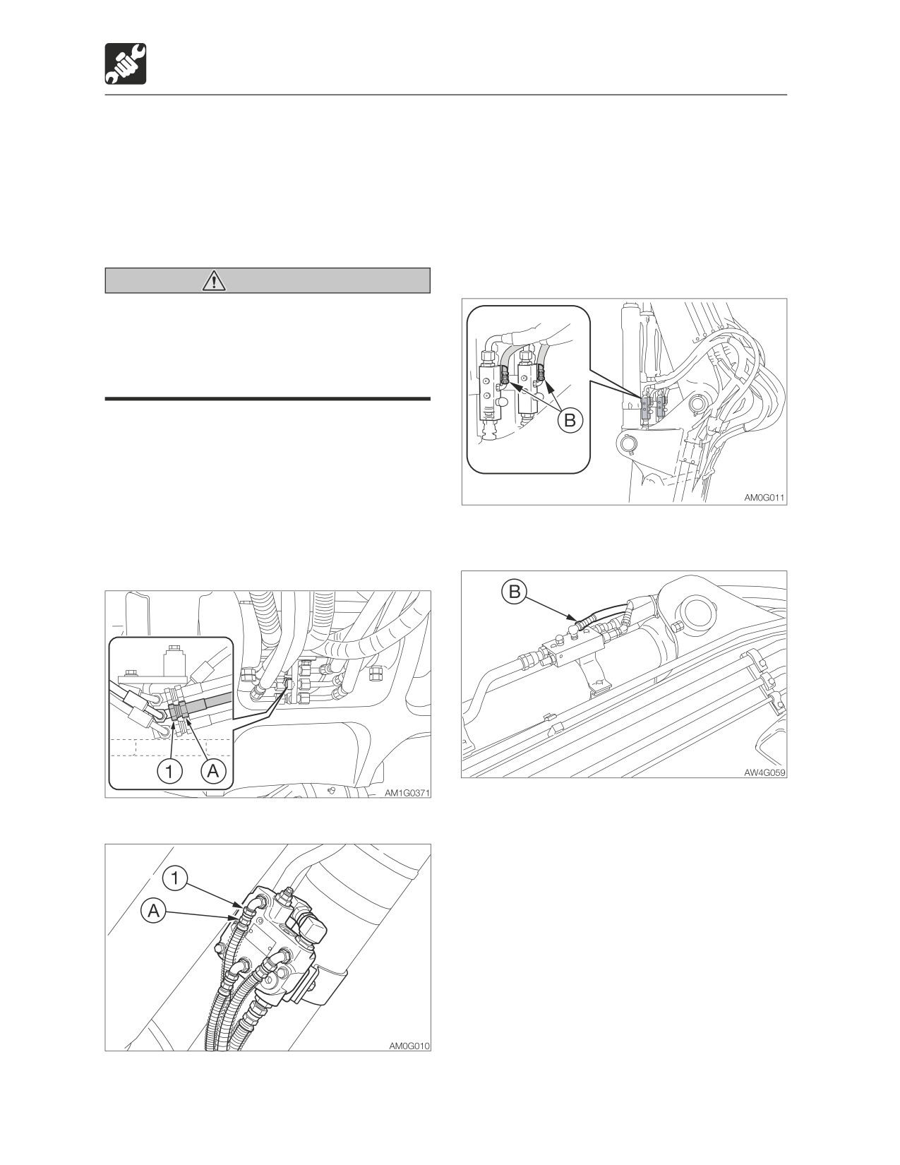
This operation is dangerous and requires
5. Slowly move the boom in the “Boom
experience. Ask your sales or service dealer
lower” direction a little until there are no
for help.
more air bubbles coming from the hose
If air is not released, the working equipment
nut (1) joint.
could become slow in reacting to the
6. Hold the hose fitting (A) in place with a
operation of the operator and show
wrench and tighten the hose nut (1).
unexpected behavior.
Second boom
Warning
When removing plugs or screws, or when
disconnecting hoses, stand to the side
and loosen them slowly to gradually
release the internal pressure before
removing.
• Emergency shut-off valve
1. Place a pan under the hose (A) or (B) to
catch the waste oil.
2. Start the engine and run it at low idle.
3. Fully lower the safety lock lever to the
unlock position.
Arm
Boom
4. Loosen the hose (B) slowly.
2-Piece boom
5. Slowly move the arm in the “Arm in”
direction a little until there are no more air
bubbles coming from the hose (B) joint.
6. Tighten the hose (B).
4. Hold the hose fitting (A) in place with a
wrench and slowly loosen the hose nut (1).
5-56
Memo
5-57
Maintenance
When required
3. Remove the key, and then check that the
When required
bucket is stable.
Replacing the bucket teeth and
the side cutters
Replace the bucket teeth if the tooth points
are worn. Do not wait until the bucket is
damaged.
Warning
• Before performing maintenance or
repairs under the machine, lower all
moveable working equipment to the
ground or in the lowermost position.
• To prevent unexpected movement,
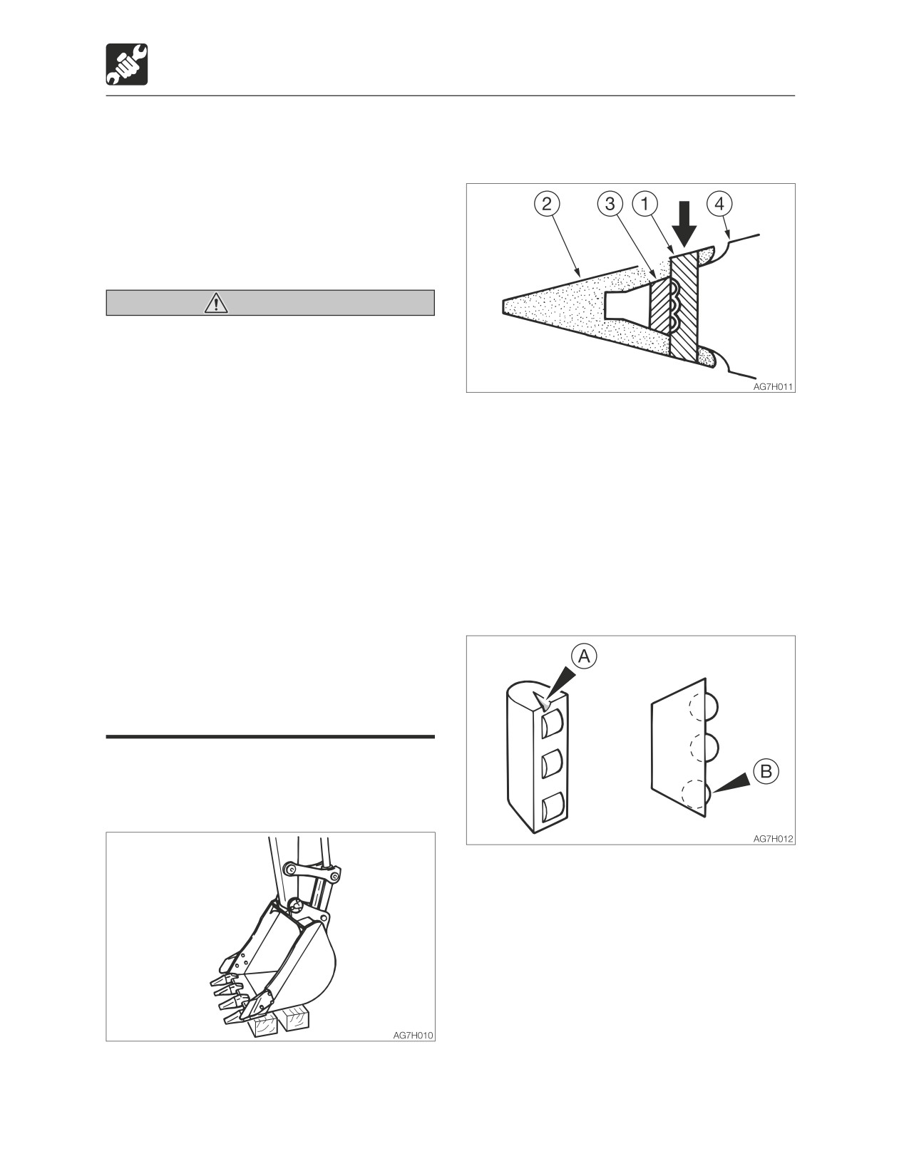
4. Knock out the locking pin (1) and remove
firmly secure the working equipment
the point (2).
when repairing or replacing the bucket
teeth or side cutter.
Note: If the drift is set against rubber pin lock
• When using a hammer, pins may fly out
(3) when it is hit, the rubber pin lock may
or metal particles may be scattered.
break. Set it against the back of the locking
This may lead to serious injury.
pin.
· If hard metal parts such as pins,
bucket teeth, side cutter or bearings
5. Remove the rubber pin lock (3). Check if
are hit with a hammer, wear protective
the rubber pin lock is still usable. Replace
gear such as safety goggles and
it if it is as follows.
gloves.
· When hitting pins or bucket teeth,
always check that there is no one in
the surrounding area.
• Do not allow unauthorized personnel in
the work area while working.
Removing
1. Clean the bucket and park the machine on
a flat and rigid ground.
A
There are cracks in the rubber and
the roller is coming off.
B
The roller is dented when pressed
with a finger.
2. Place the bucket with its bottom flat on
the blocks so that the locking pin can be
knocked out.
5-58
Maintenance
When required
Installation
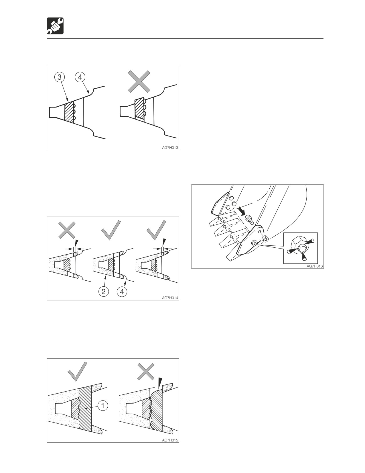
4. Knock out the locking pin (1).
Check that the end surfaces of the locking
pin just knocked out are aligned with the
upper and lower surface of the point. Do
not use the worn locking pin.
The life of the teeth can be lengthened
and the frequency of its replacement can
be reduced by turning it upside down so
that it will wear evenly.
Replace the rubber pin lock and locking
pin at the same time as replacing the
teeth. This makes it possible to prevent
the teeth from falling out
1. Remove the dirt on the surface of adaptor
and the inner part of tooth, make the
• Side cutter
better contact on the mating part.
Installation
2. Push rubber pin lock (3) into the welding
adaptor (4).
Do not let the rubber pin lock stick out
from the welding adaptor surface.
1. Insert the bolts from the inner of the
bucket and tighten the side cutter with
nuts.
Tightening torque: 475 N·m (350 ft-lb.)
3. Install the point (2) onto the welding
2. Caulk the bolts with a punch at three
adaptor (4).
spots along the periphery of the screw to
Insert the point so that the surface behind
prevent the nuts from coming loose.
the point’s pin hole is aligned with the
surface behind the welding adapter’s pin
hole.
5-59
Maintenance
When required
Replacing the bucket
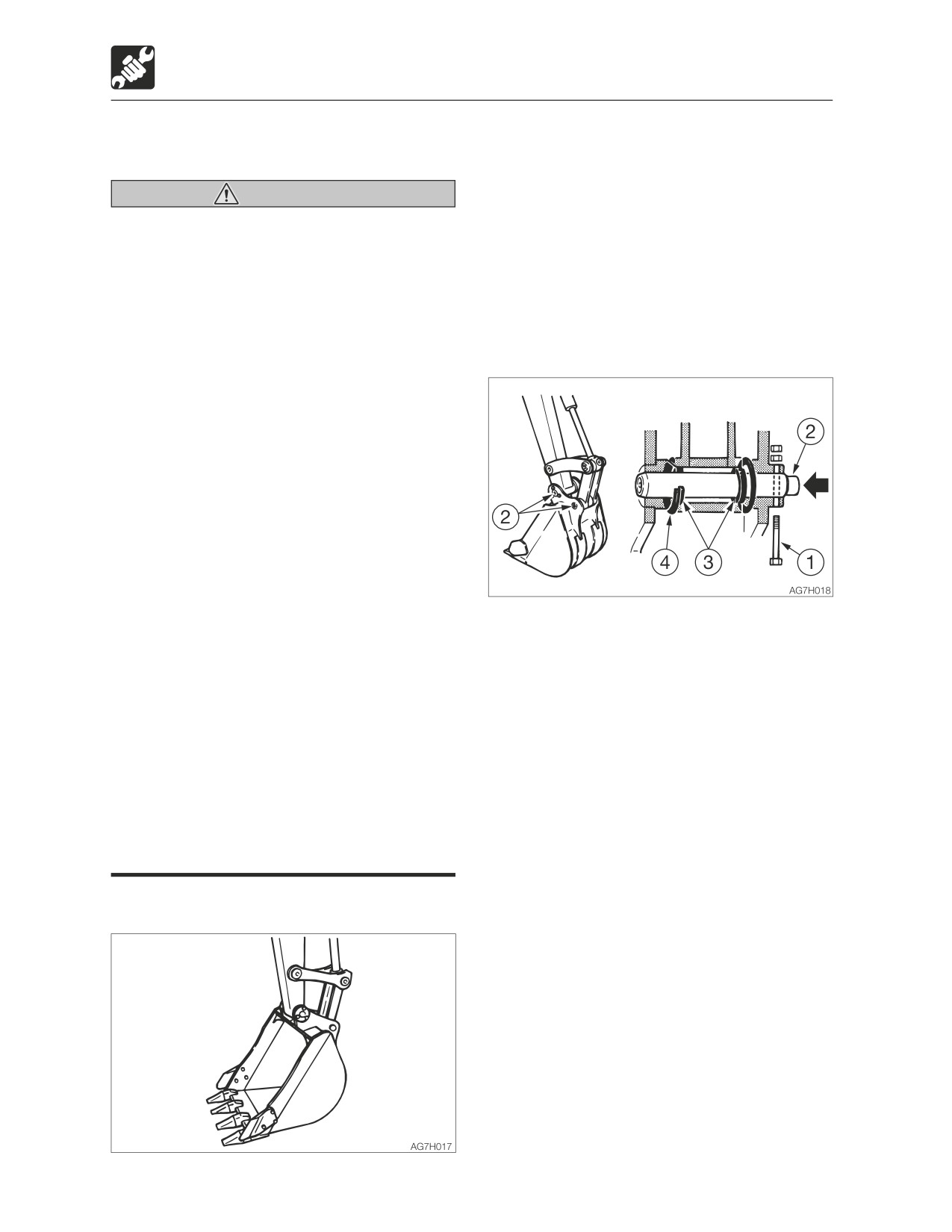
1. Lower the bucket to the ground as shown
on the figure above in a stable position.
Warning
Note: When removing pins, set the bucket
• Before performing maintenance or
so that it is barely touching the ground If the
repairs under the machine, lower all
bucket is firmly touching the ground, the
working equipment to the ground or in
resistance will be great and it will be difficult
the lowermost position.
to remove the pin.
• If maintenance must be performed with
the engine running, always work as a
2. Set the safety lock lever to the locked
two person team communicating each
position and stop the engine.
other.
· One person must sit in the operator’s
seat so that he/she can immediately
stop the engine when necessary. He/
she must take care not to touch the
lever or pedal unless necessary.
· The one who performs maintenance
must make sure to keep his/her body
or clothing away from the moving part
of the machine.
• When using a hammer, pins may fly out
or metal particles may be scattered.
This may lead to serious injury.
3. Remove the bolt (1).
· If hard metal parts such as pins,
4. Hammer the pin (2) out of the bucket.
bucket teeth, side cutter or bearings
5. Remove the bucket.
are hit with a hammer, wear protective
Inspect the pin seal (3) and replace it if it is
gear such as safety goggles and
deformed or damaged. (See next page.)
gloves.
· When hitting pins or bucket teeth,
always check that there is no one in
the surrounding area.
• When aligning the pin holes, always do
so by checking them visually. Do not
insert your finger in the pin hole, or you
could lose your finger.
Removing
5-60
Maintenance
When required
Installation
5. Adjust the gap between the bucket and
the arm.
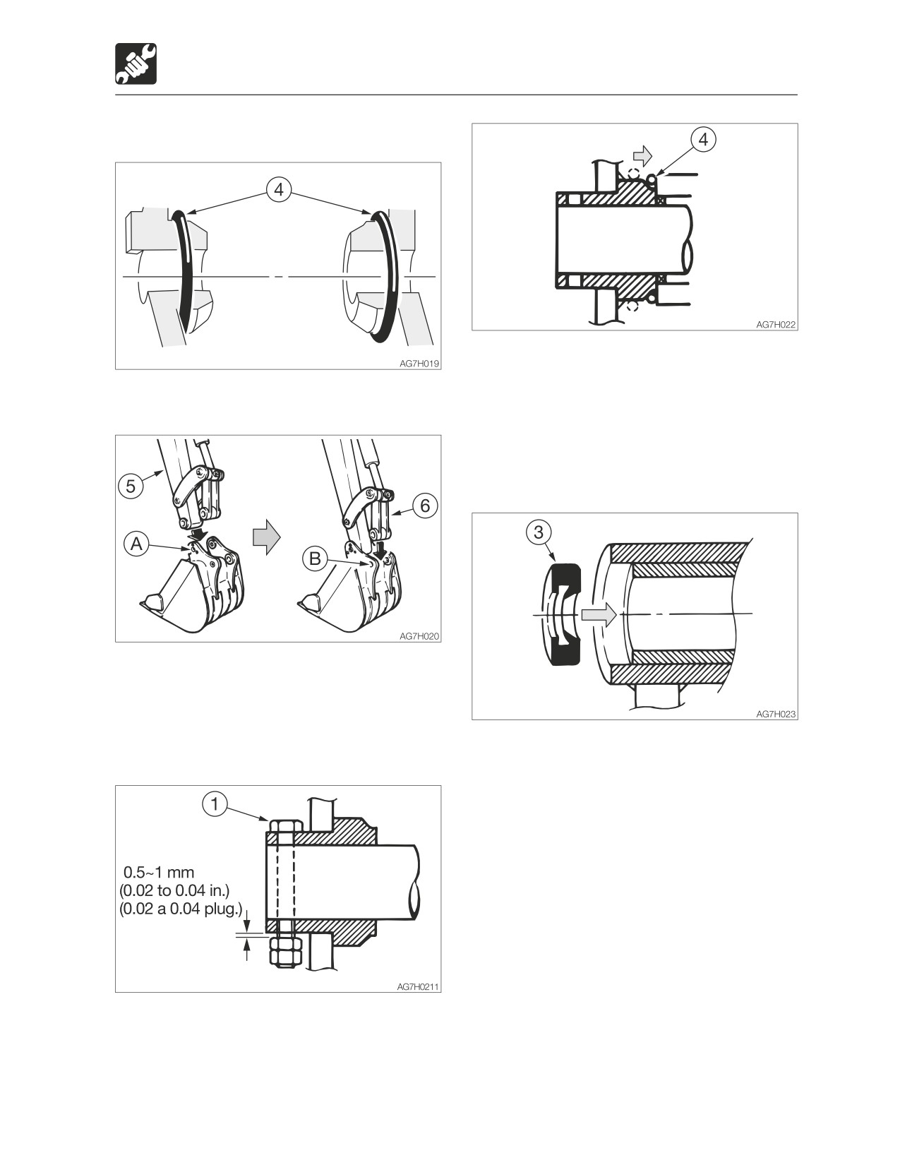
1. Set the O-ring (4) on the bucket as shown
Refer to “Adjusting the gap between the
on the figure above.
bucket and arm (If equipped)” on page
5-62.
6. Slide the O-ring (4).
Replacing the pin seal
2. Align the pin hole (A) on the bucket with
the pin hole on the arm (5), and install the
pin (2).
3. Operate the cylinder, align the pin hole (B)
on the bucket with the pin hole on the link
1. Set the pin seal (3) in the direction shown
arm (6), and install the pin (2).
on the figure above.
2. Use a mallet to slowly press the pin seal
in. Be careful not to damage the seal.
4. Align the turn prevention holes, and then
install the bolt (1) and the nut. Be sure to
leave a gap of about 0.5 to 1 mm (0.02 to
0.04 in.) between the nut and bucket
bush, or the nut will come loose.
5-61
Maintenance
When required
Adjusting the gap between the
bucket and arm (If equipped)
Warning
• Before performing maintenance or
repairs under the machine, lower all
working equipment to the ground or in
the lowermost position.
• To prevent unexpected movement,
securely block the working equipment
when adjusting the gap.
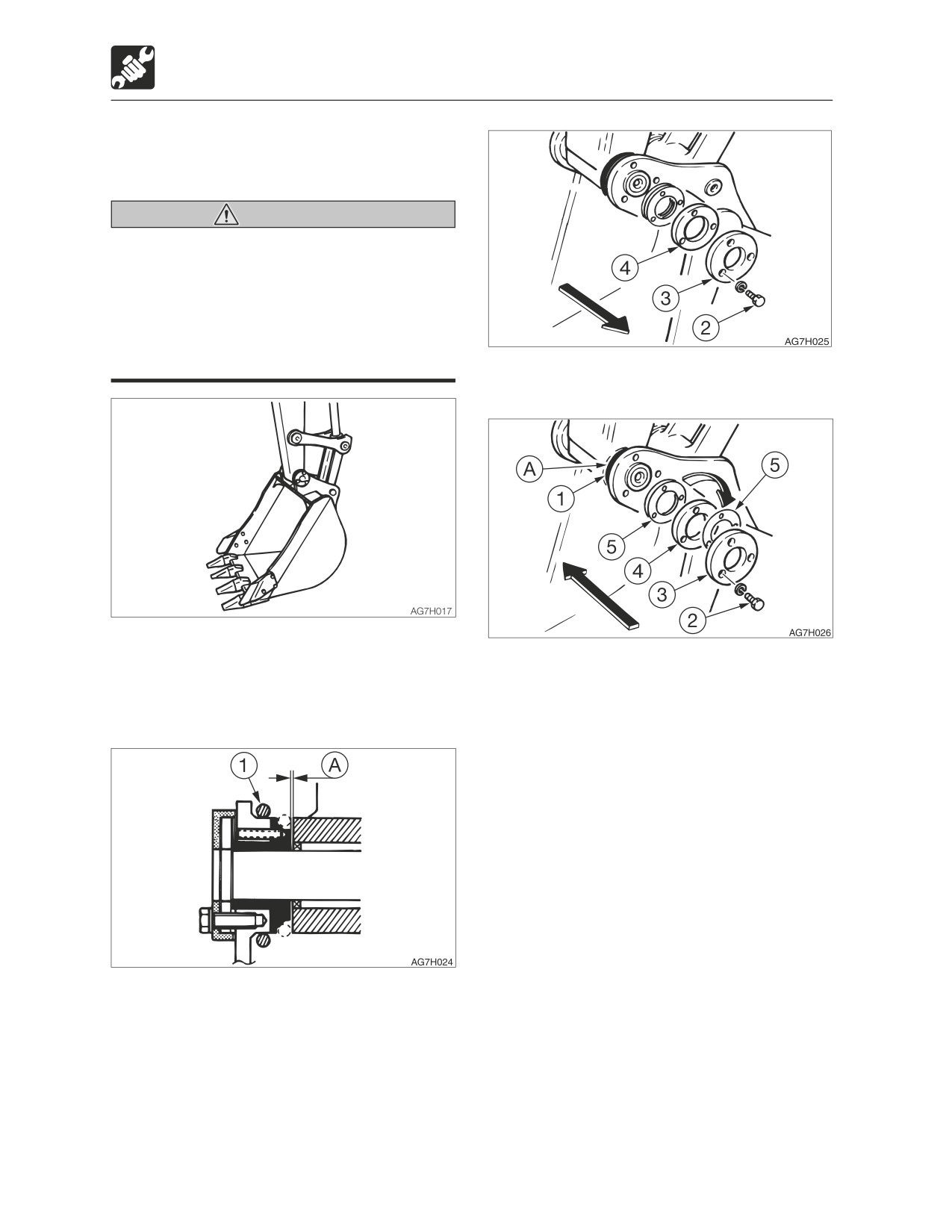
4. Remove the three bolts (2), the end plate
(3) and flange (4).
1. Lower the bucket to the ground as shown
on the figure above in a stable position.
5. Pull out the adjustment shim(s) (5)
2. Check that the bucket dose not move,
corresponding to the gap (A) from
and then set the safety lock lever to the
between the flange (4) and the bucket
locked position and stop the engine.
body.
Adjustment shim thickness : 0.5 mm (0.02
in.)
Be careful that the gap is no less than 0.5
mm (0.02 in.) after adjustment.
Note:
Example (for a gap of 2 mm or 0.08 in.):
2 mm - 0.5 mm (standard value)= 1.5 mm
(0.06 in.)
In the above example, three shims (5) should
be removed.
3. Move the O-ring (1) to bring the gap (A)
6. Insert the adjustment shim(s) (5) removed
into view and measure the width of the
in step 5 above between the end plate (3)
gap (A).
and the flange (4), and then fasten it in
The gap (A) should be 0.5 mm (0.02 in.).
place with the three bolts (2).
Swing the upperstructure slightly to the left
· Tightening torque for bolts (2): 83 N·m
and lightly press the arm point to the left
(61.5 ft-lb.)
side of the bucket (the side without an
7. Return the O-ring (1) to the original
adjuster).
position.
5-62
Maintenance
When required
Inspecting and replenishing the
Draining the water from the
windshield washer fluid
water separator
Warning
Warning
Choose ethyl alcohol as washer solution.
• Do not smoke or permit open flames
Do not use methyl alcohol as washer
while handling fuel or working on the
solution. It could damage the eyes.
fuel system.
• Stop the engine in a well-ventilated
Use a windshield washer fluid designed
place and allow it to cool down before
specifically for motor vehicles. Follow the
performing maintenance.
instructions included with the washer fluid.
• Clean up spilled fuel immediately.
<TB285>
Inspection
1. Open the side cover.
<TB290>
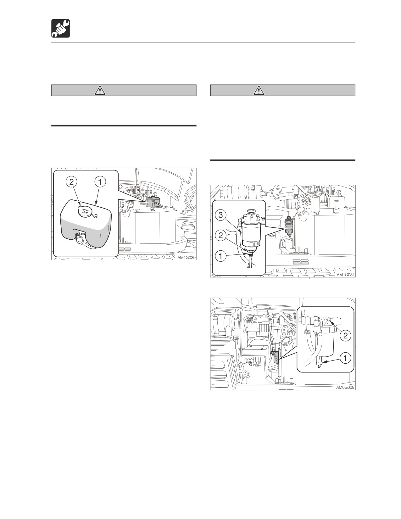
2. Inspect the washer tank (1) and add
washer fluid if the level is low.
Replenishing
1. Mix the washer fluid to the prescribed
concentration.
2. Remove the cap (2) and add washer fluid.
Keep the dust away while replenishing the
washer fluid.
3. Install the cap (2).
1. Open the side cover.
2. Place a pan under the drain valve (1) to
catch fuel.
3. Open the drain valve (1) and drain the
water.
If the water does not drain easily, loosen
the plug (2). <TB290>
4. Close the drain valve (1) and tighten the
plug (2) <TB290>.
Refer to “Bleeding air from the fuel system”
on page 6-8.
5-63
Maintenance
When required
Lubricating the levers and pedals
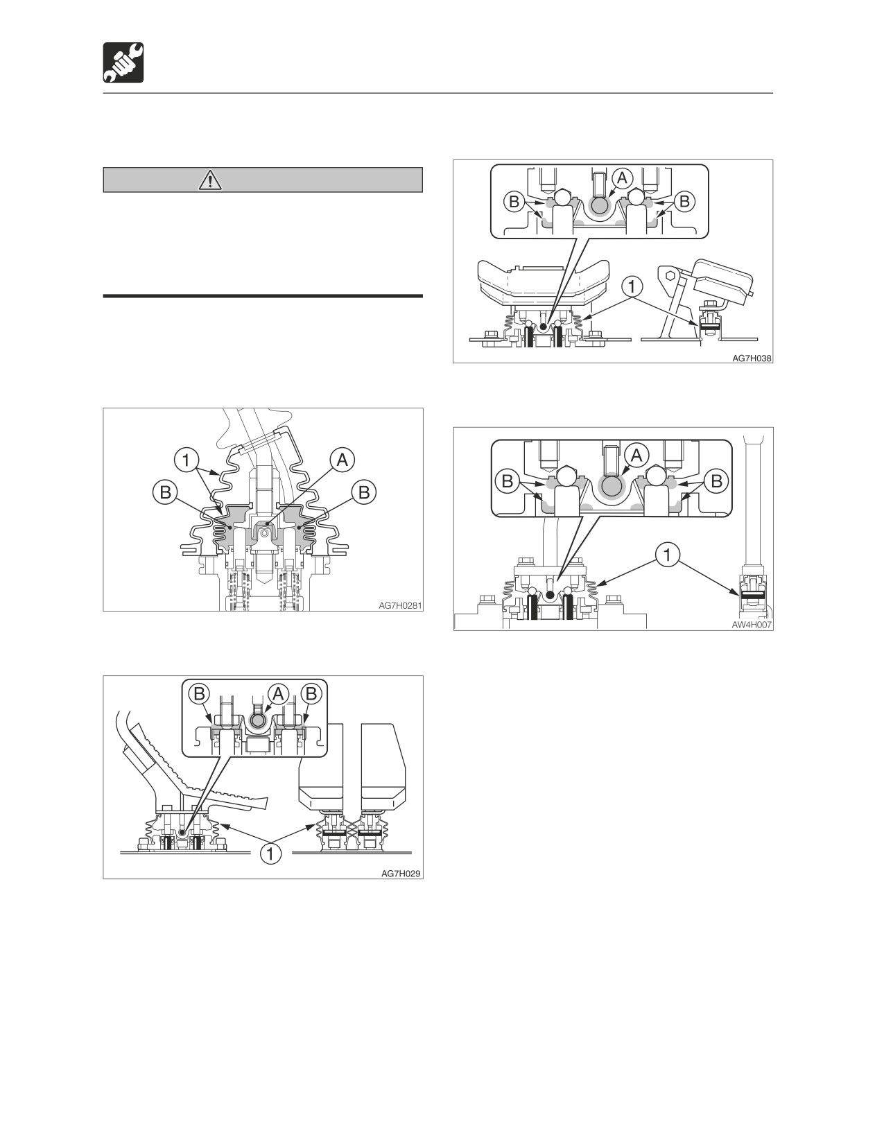
Boom swing pedal
Warning
Set the machine to the parking posture,
stop the engine, remove the starter key
and store it. Failure to do so may result in
the machine moving abruptly, leading to
serious injury or death.
If the levers or pedals no longer move
smoothly, grease them.
Operating levers
Dozer blade lever
Travel levers
1. Remove the lower mount section of the
boot (1) and turn it upward.
2. Wipe off the old grease.
3. Apply grease to points (A) and (B).
4. Set the boot (1) back as it was.
5-64
Maintenance
When required
Inspecting the rubber crawlers
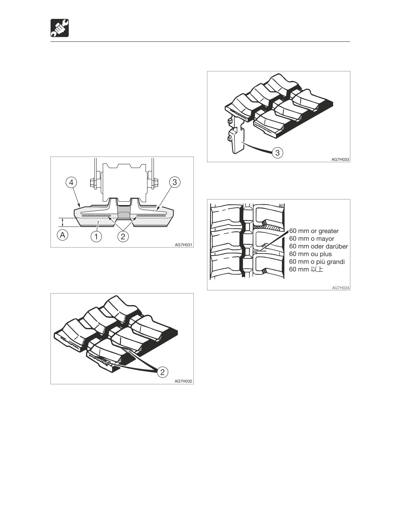
(3) Metal core
Repair or replace the rubber crawlers if their
condition becomes as described below.
Consult your sales or service dealer for repair
or replacement.
Rubber crawler
Replace the crawler if the entire crawler is
stretched and cannot be adjusted.
(1) Lug
Replace if even one metal core is off.
(4) Rubber
Replace if the height of (A) is 5 mm (0.2 in.)
or below.
(2) Steel cord
Repair if there are cracks of 60 mm (2.4 in.)
or greater in length.
If the steel cord is visible, repair as soon as
possible, regardless of the length of the
crack.
Replace if the steel cord is exposed for two
links or more.
Replace if the half or more of the steel cords
on one side are cut.
5-65