Takeuchi Mini excavator TB230 (No.130000003~). Operator's Manual (2014) - page 7

TROUBLESHOOTING
OTHER SYMPTOMS
Symptoms
Major causes
Remedies
Engine exhaust is
• Air cleaner is clogged
• Clean the air cleaner.
occasionally black
Refer to page 5-38.
• Engine control system is
• Adjust or repair (ask your
faulty.
sales or service dealer).
• Fuel line is faulty.
• Adjust or repair (ask your
sales or service dealer).
• Clogging in the exhaust line.
• Adjust or repair (ask your
sales or service dealer).
• DPF is faulty.
• Adjust or repair (ask your
sales or service dealer).
Irregular noise is produced
• Low quality fuel is being
• Replace the fuel.
from the engine
used
(combustion or mechanical
• Engine is overheating
• Refer to “If the engine
noise)
overheats” on page 6-3.
• Damage inside the muffler
• Replace the muffler.
For replacement, ask your
sales or service dealer.
6-18
TROUBLESHOOTING
LOWERING THE BOOM TO THE GROUND
• Do not loosen or remove the hoses not
LOWERING THE BOOM TO
located in the specified places. Oil may
spurt out if wrongly handled.
THE GROUND
If the hoe attachment must be lowered to the
ground while the engine is stopped, use the
Equipped with emergency shut-off valve
following procedure.
Procedure 1 (machines with an
accumulator)
Perform this operation within 10 minutes
after the engine stopping.
1. Sit at the operator’s seat.
2. Turn the starter switch to the ON position.
3. Lower the safety lock lever to the unlock
position
4. Slowly push the operating lever forward to
lower the boom.
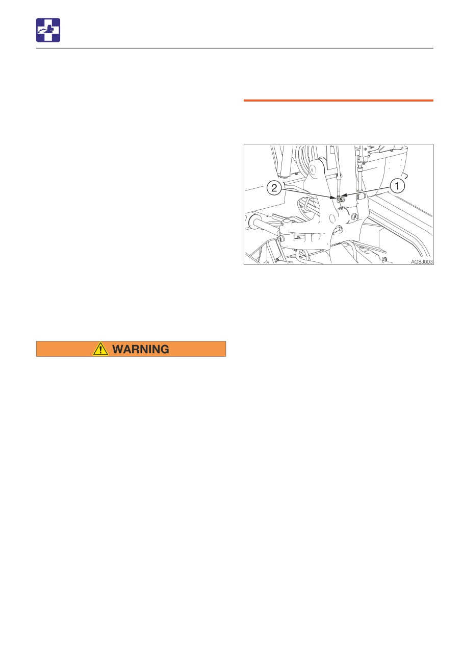
1. Place a pan under the hose to catch the
Procedure 2 (machines without an
waste oil.
accumulator)
2. Hold the hose fitting (1) with a wrench and
This operation is dangerous and requires
slowly loosen the hose nut (2) with another
experience. Ask your sales or service dealer
wrench.
for it.
3. The oil in the boom cylinder is drained and
the hoe attachment is lowered.
4. After the hoe attachment is lowered to the
• Stop the engine and allow the machine
ground, check the safety and stability of
to cool down before performing
the machine.
maintenance.
5. Hold the hose fitting (1) with a wrench and
· The engine and the hydraulic system
tighten the hose nut (2) with another
and many other parts of the machine
wrench.
are hot immediately after the engine is
· Tightening torque: 31.4 N·m (23.1 ft-lb.)
stopped. Touching these parts will
cause burns.
· The hydraulic oil is also hot and under
high pressure immediately after the
engine is stopped.
Be careful when loosening the caps or
plugs. Working on the machine under
these conditions could result in burns
or injuries due to the hot oil spurting
out.
• Keep away from the working area when
the hoe attachment is lowered. You may
be hit by dirt falling out of the bucket or
the hoe attachment as it drops.
• Slowly turn the hose nut and lower the
boom at a slow pace.
6-19
TROUBLESHOOTING
TOWING
Towing the machine
TOWING
Use the procedure described below to tow
heavy objects or the machine itself if it
should get stuck in the mud and not be able
When towing, serious injury or death
to get out on its own.
could result, if performed incorrectly or
the wire rope being used is inappropriate
or not properly inspected.
• It becomes dangerous if the wire rope
breaks or becomes disengaged. Use a
wire rope appropriate for the required
tractive force.
• Do not use a wire rope that is kinked,
twisted or otherwise damaged.
• Do not apply heavy loads abruptly to
the wire rope.
• Wear safety gloves when handling the
AG8A001
wire rope.
• Permissible forces: 47.0 kN (10566 lbf)
• Make sure there is an operator on the
Do not tow using only a towing hole on one
machine being towed as well as on the
side.
machine that is towing.
• Never tow on slopes.
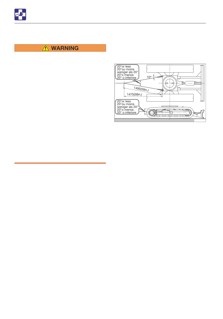
1. Attach the wire rope to the shackle (1).
• Do not let anyone come near to the wire
2. Fasten the shackle (1) to the towing holes
rope while towing.
(2).
3. Make sure that the wire rope is at a cone
IMPORTANT: Do not tow a machine if its
angle of 20° or less to the travel frame.
engine does not start or if the machine
4. Move the machine to tension the wire
does not run. Doing so could damage the
rope.
machine being towed.
5. Operate the machine slowly and tow.
IMPORTANT: Be sure to follow the steps
below closely when using the towing hole
to tow. Failure to heed even one of the
steps may cause damage to the towing
hole or other parts of the frame.
6-20
TROUBLESHOOTING
IF THE CAB OR CANOPY IS DAMAGED
IF THE CAB OR CANOPY IS
DAMAGED
Immediately replace the damaged cab or
canopy. Serious injury or death may occur
if the machine is operated with damaged
cab/canopy.
Do not operate the machine until the
replacement is complete. Do not try to
repair the damaged cab or canopy by
welding. Doing so could endanger the
safety of the cab/canopy.
Canopy part number: 05584-00085
Cab part number: 03586-00070
6-21
SPECIFICATIONS
7-1
SPECIFICATIONS
BASIC SPECIFICATIONS
BASIC SPECIFICATIONS
Type
Canopy
Cab
MASS
Operating mass
kg (lb)
Rubber crawlers
2885 (6360)
2950 (6505)
PERFORMANCE
Heaped
0.068
(2.4)
Bucket capacity
m3 (cu. ft.)
(Standard bucket)
Struck
0.051
(1.8)
Slew speed
min-1 (rpm)
10.3
(10.3)
1st
2.9
(1.8)
Travel speed
km/h (mph)
Rubber crawlers
2nd
5.2
(3.23)
Gradeability
(degrees)
30
Ground pressure
kPa (psi)
Rubber crawlers
30.1
(4.63)
31.6
(4.58)
Sound power level
LWA 93
Noise level
dB (A)
Sound pressure level
LpA 78
ENGINE
Yanmar
Yanmar
Manufacturer and model
3TNV88F-
3TNV88F-
EPTB1
EPTB
Net
kW/min-1 (hp/rpm)
18.2/2400 (24.4/2400)
(ISO 14396)
Rated output
Net (ISO 9249/
kW/min-1 (hp/rpm)
17.6/2400 (23.6/2400)
SAEJ1349)
Displacement
ml (cu.in.)
1642 (100.2)
Starter
V-kW
12-1.7
Alternator
V-kW
12-0.66
Battery (IEC 60095-1)
V-A·h
12-64
7-2
MEMO
7-3
SPECIFICATIONS
MACHINE DIMENSIONS
MACHINE DIMENSIONS
7-4

SPECIFICATIONS
MACHINE DIMENSIONS
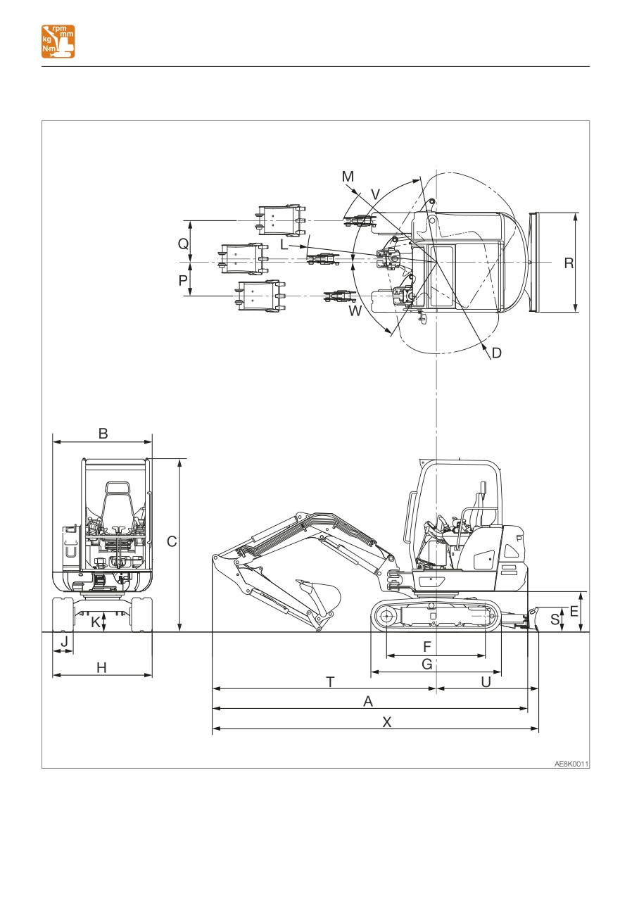
Unit: mm (inch)
Long arm
Item
Rubber crawlers
A
Overall length
4595 (180.9)
B
Upperstructure overall width
1460 (57.5)
2540 (100)
C
Overall height
2525 (99.3)**
D
Slew radius
1330 (52.4)
E
Clearance height under upperstructure
590 (23.2)
F
Crawler base
1440 (56.7)
G
Crawler overall length
1900 (74.9)
H
Crawler overall width
1450 (57.1)
J
Crawler shoe width
300 (11.8)
K
Ground clearance of undercarriage
305 (11.9)
L
Minimum radius of equipment and attachment
1895 (74.7)
M
Minimum radius of equipment at maximum front offset
1505 (59.2)
P
Offset distance of bucket (right swing)
490 (19.3)
Q
Offset distance of bucket (left swing)
610 (23.9)
R
Dozer blade width
1450 (57.1)
S
Dozer blade height
355 (14.0)
T
Front distance to axis of rotation
3265 (128.5)
1455 (57.3)
U
Dozer blade distance to axis of rotation
1480 (58.3)*
V
Boom swing angle (Left)
79°
W
Boom swing angle (Right)
58°
4730 (186.3)
X
Overall length (dozer blade at rear)
4755 (187.2)*
: With an angle dozer blade
** : Cab
7-5
SPECIFICATIONS
OPERATING RANGES
OPERATING RANGES
7-6

SPECIFICATIONS
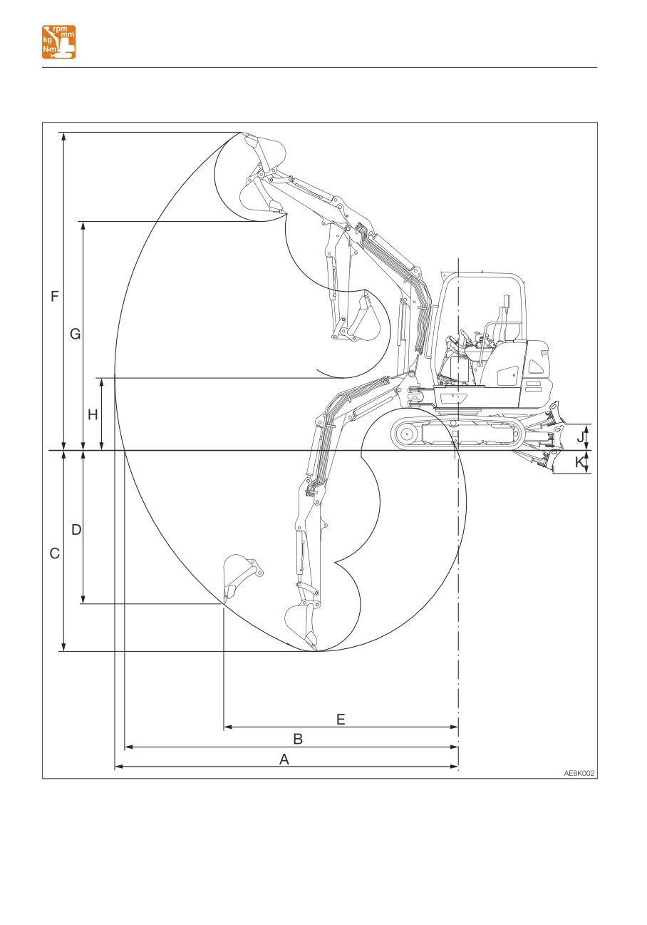
OPERATING RANGES
Unit: mm (inch)
Long arm
Item
Rubber crawlers
A
Maximum reach
4850 (190.9)
B
Maximum reach at ground reference plane
4710 (185.4)
C
Maximum digging depth
2835 (111.6)
D
Maximum vertical digging depth
2165 (85.2)
E
Reach at maximum vertical digging depth
3310 (130.4)
F
Maximum height of cutting edge
4490 (176.7)
G
Maximum dumping height
3230 (127.2)
H
Minimum dumping height
1020 (40.2)
380 (15.0)
J
Dozer blade maximum lifting
370 (14.5)*
310 (12.2)
K
Dozer blade maximum lowering
325 (12.9)*
*: With an angle dozer blade
7-7
SPECIFICATIONS
LIFTING CAPACITIES
LIFTING CAPACITIES
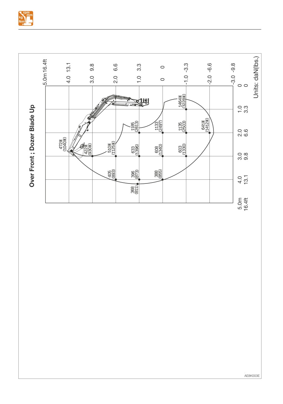
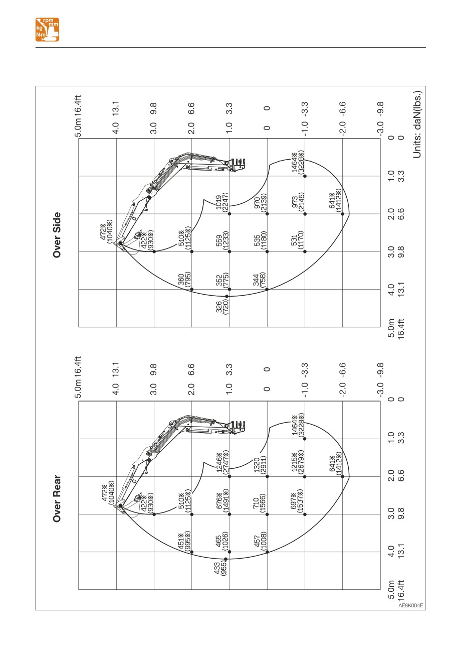
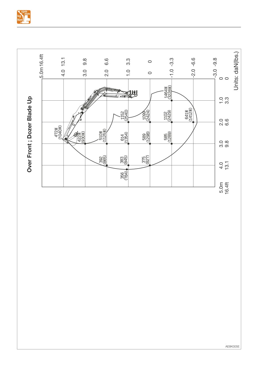
Rated lift capacity chart
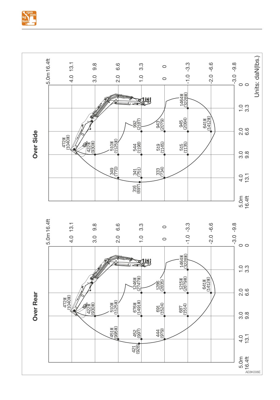
• Do not attempt to lift or hold any load
• The loads in the charts do not exceed 87%
that is greater than these rated values at
of hydraulic lift capacity or 75% of tipping
their specified load radii and height.
load.
• The rated lift capacities are based on
• Figures marked with an asterisk (*) are
the machine being level and situated on
hydraulically-limited capacities.
a firm supporting surface. For safe
• The mass of slings and any other lifting
lifting, the operator is expected to make
devices shall be deducted from the rated
due allowance for the particular job
load to determine the net load that may be
conditions such as soft or uneven
lifted.
ground, non-level condition, load to the
• The load point is the bucket hinge pin, and
machine sides, hazardous conditions,
the bucket posture is with the standard
experience of personnel, etc. The
bucket completely retracted under the arm.
operator and other personnel should
• Unit: daN (lbs)
fully acquaint themselves with the
operator’s manual furnished by the
Load hooking system
manufacturer before operating this
A load hooking system must be provided
machine. When operating the machine,
with the following capabilities.
the safety rules of the equipment must
1. A system which can withstand twice the
also be followed.
rated lift capacity no matter at what
• Do not travel while lifting a load; It is
position the load is applied.
very dangerous.
2. A system that poses no risk of the lifted
load falling from the hooking device. For
example, equipped with a hook slippage
prevention device.
3. A system that poses no risk of the hooking
system slipping from the hoe attachment.
7-9
SPECIFICATIONS
LIFTING CAPACITIES
<Cab> Long arm
7-10
SPECIFICATIONS
LIFTING CAPACITIES
<Cab> Long arm
7-11
SPECIFICATIONS
LIFTING CAPACITIES
<Canopy> Long arm
7-12
SPECIFICATIONS
LIFTING CAPACITIES
<Canopy> Long arm
7-13
OPTIONS
GENERAL PRECAUTIONS
• Use the proper procedure when
GENERAL PRECAUTIONS
mounting a boom or arm; otherwise
SAFETY PRECAUTIONS
serious damage could result. Consult
your sales or service dealer for help.
When removing or installing an
attachment or optional part, take the
CAUTIONS WHEN INSTALLING
following precautions.
ATTACHMENTS
• Consult with Takeuchi before installing
an optional attachment.
Be sure to perform a test operation after an
• Do not use any attachments not
optional or other special attachment has
approved by Takeuchi. Doing so may
been replaced. Inspect the hydraulic oil level
cause safety problems. Or, it may
and recharge it as necessary. Consult your
adversely affect the machine’s operation
sales or service dealer for detailed
or service life.
procedures on installing/removing
• We will not be held responsible for any
attachments.
injuries, accidents or damage to its
products caused by the use by a non-
approved attachment.
• Select a firm, level work area. Also, be
sure to park in a well ventilated place.
• Clear obstacles and dangerous objects,
and clean up spilled fuel immediately.
• When hoisting, be sure to designate a
person to act as a signalman.
Follow the instructions of the signalman
regarding the procedure and measures.
• When it is necessary to temporally
place a heavy object or an attachment
on the ground during removal or
installation, be sure to place it in a
stable position.
• Keep everyone out of the area when
hoisting. There is a hazard of objects
falling or contacting with people in the
area.
• Use a crane to move heavy objects (25
kg (55 lb.) or greater).
• Before removing a heavy object, be sure
to put a support to it. When lifting with a
crane, pay attention to the center of
gravity of the load to keep the machine
in balance.
• Do not operate the machine while the
load is lifted by a crane stand.
8-2
OPTIONS
GENERAL PRECAUTIONS
CAUTIONS WHEN OPERATING
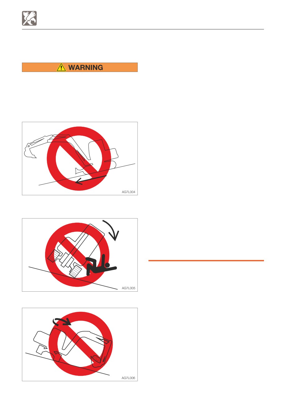
• Slewing on slopes
ATTACHMENTS
• If there is a heavy attachment is
installed, the machine takes longer
distance than usual to come to a
complete stop when the stopping
Long attachments reduce stability of the
operation is performed. Carefully judge
machine. The machine may tip over if it
the distance so as not to bump into an
loses the balance when traveling or
object around the machine. Keep a safe
slewing on slopes.
distance from surrounding obstacles.
Never perform the operations listed below
When a heavy attachment is installed,
as they are extremely dangerous.
natural drop (the gradual dropping of
the attachment under its own weight
when it is stopped in midair) increases.
• The machine can tip over more easily in
the lateral direction than in the
longitudinal direction.
· Do not slew sideways with a heavy
load at the how attachment. In
particular, do not slew sideways on
slopes.
· The attachment is heavier for
machines equipped with breakers or
crushers than for machines equipped
• Traveling down the slopes with the
with the standard bucket. Do not
attachment raised
operate such machines sideways,
especially digging downhill.
• When a long arm is installed, the
operating range increases. Carefully
judge the distance so as not to bump
into an object around the machine.
Keep a safe distance from surrounding
obstacles.
• Traveling across slopes
8-3
OPTIONS
ATTACHMENT COMBINATION TABLE
ATTACHMENT COMBINATION TABLE
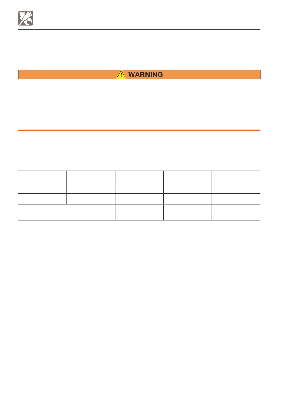
The table below shows which bucket should be installed when the machine is using a
standard arm, middle arm or long arm. Select a proper bucket by following the table.
• Consult with Takeuchi before installing an optional attachment.
• Do not use any attachments not approved by Takeuchi. Doing so may cause safety
problems. Or, it may adversely affect the machine’s operation or service life.
• We will not be held responsible for any injuries, accidents or damage to its products
caused by the use by a non-approved attachment.
• The swing stopper must be installed when a bucket wider than a 640W (standard)
bucket is installed. Failure to do so may result in the bucket hitting the machine body.
√ :Can be used.
∆ :Can be used only for light operations (digging and loading of dry and loose soil or mud)
—:Cannot be used.
Total bucket mass = Bucket mass + Heaped bucket load (specific gravity: 1.8)
Bucket cutting
Middle arm
Long arm
Rated capacity
Bucket
width
1290 mm
1445 mm
m3 (cu.yd.)
mm (inch)
(50.8 in.)
(56.9 in.)
460 W (S.T.D.)
0.068
(0.081)
460 (18.1)
√
√
Total bucket weight= Within 178 kg
Within 460 (18.1)
√
√
(392 lb.)
8-4
OPTIONS
SELECTING A LEVER PATTERN
SELECTING A LEVER PATTERN
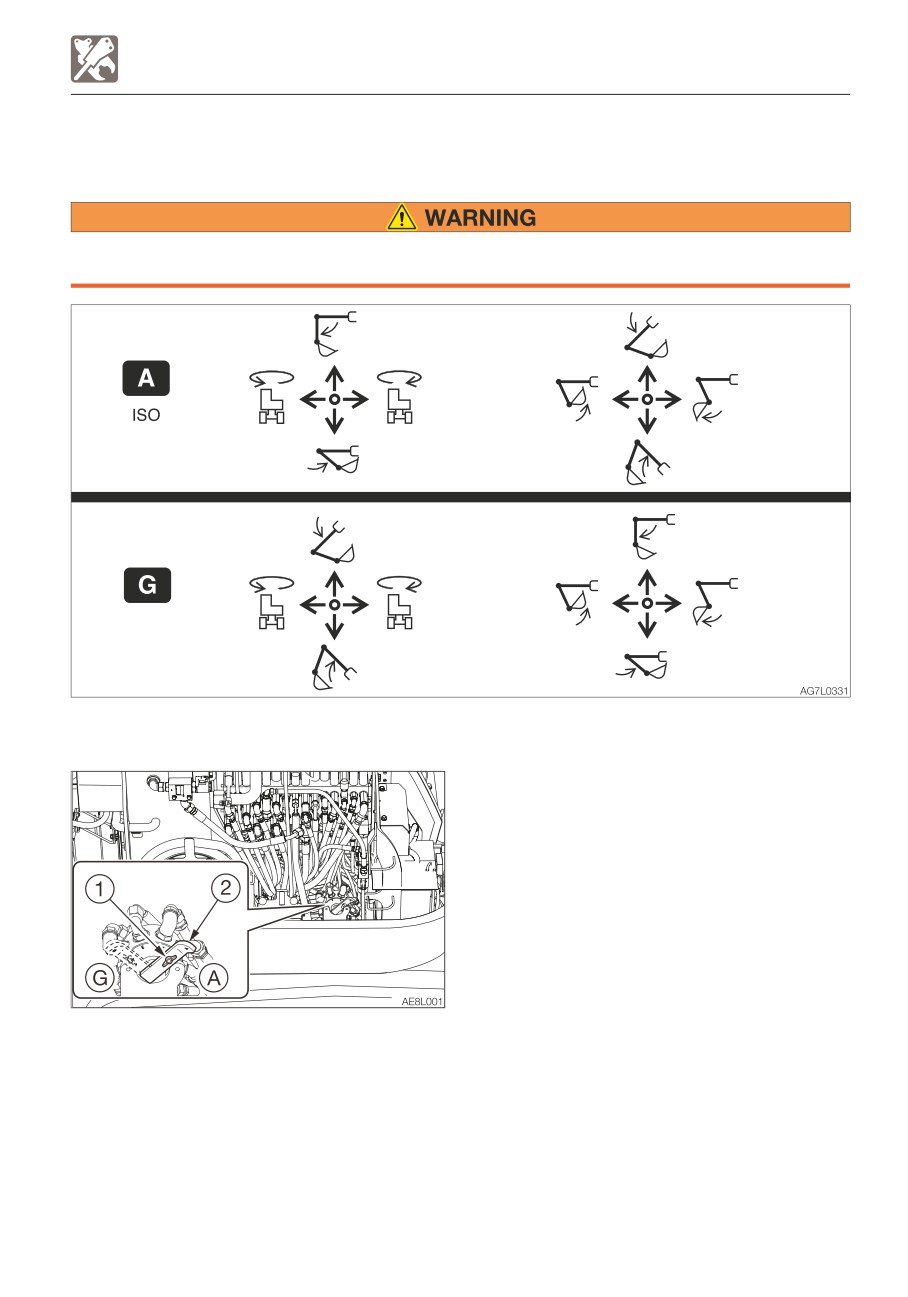
The operating pattern of the left and right operating levers can be changed.
Before starting the engine, check the selector to see which operating pattern the left
and right operating levers are set.
SWITCHING THE LEVER PATTERN
1. Park the machine on a flat and rigid
ground, and stop the engine.
2. Open the right side cover.
3. Loosen the wing bolt (1).
4. Turn the selector valve lever (2) to change
the pattern.
5. Tighten the wing bolt (1) and fasten the
lever (2) in place.
6. Close the right side cover.
7. Confirm the lever pattern.
(A) : ISO pattern
(G) : G pattern
8-5
OPTIONS
HYDRAULIC BREAKER
HYDRAULIC BREAKER
For handling of the breaker, read the
hydraulic breaker’s manual, provided
separately.
IMPORTANT: When installing an
attachment, make sure that it is
appropriate for the machine being used.
Contact your sales or service dealer for
advice on selecting attachments.
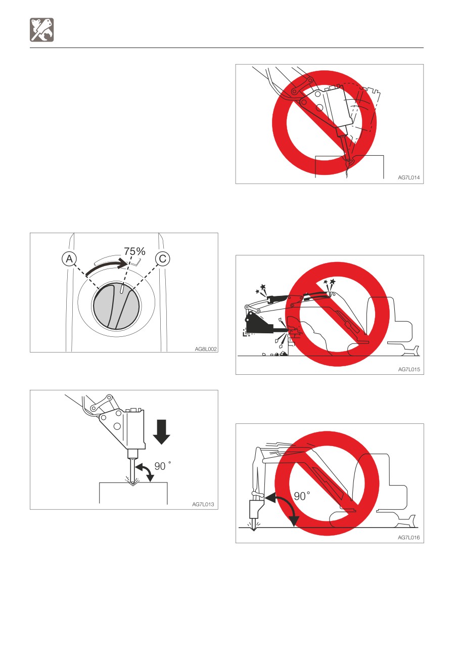
• Do not pry with the chisel or do not pry
while pounding.
CAUTIONS ON OPERATING
• Do not move the chisel while pounding.
• Do not pound continuously for over 30
seconds on the same surface.
• Start the engine and run it at 75% of the
maximum speed.
• Do not pound with the cylinder fully
extended or retracted (at the stroke end).
Leave a margin of at least 50mm(2 in).
• Pound with the chisel pressed
perpendicular to the surface to be
pounded.
• When pounding, press the chisel properly
• Do not pound with the arm placed
against the object to be broken so as to
perpendicular to the ground surface.
avoid pounding the air.
8-6
OPTIONS
HYDRAULIC BREAKER
REPLACING THE HYDRAULIC OIL
REGULARLY
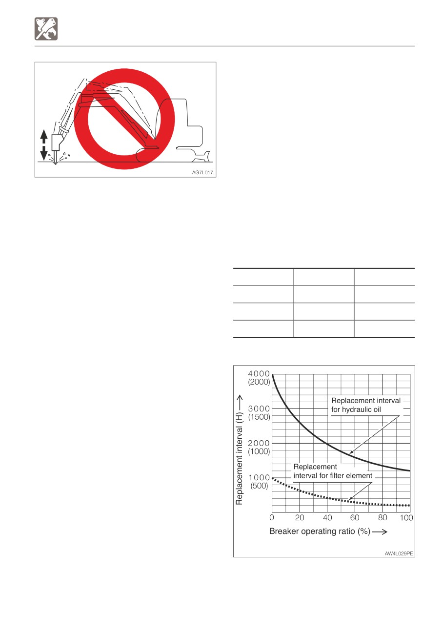
When a hydraulic breaker is used, the oil
deteriorates more quickly than that used for
a usual operation. Be sure to replace the
hydraulic oil and the return filter elements.
• Failure to replace these in time can lead to
damage to the machine and the breaker
hydraulic system. To improve the service
life of the hydraulic systems, be sure to
• Do not drop the breaker itself on the object
replace the hydraulic oil and return filter
to be broken in order to break it.
element after the number of hours shown
• Do not move objects to be broken or rocks
on the diagram below.
with the breaker itself.
• When replacing the hydraulic oil, clean the
• Slew the machine occasionally to cool the
suction strainer.
engine.
• If a hydraulic hose is vibrating abnormally,
Replacement interval (hours)
nitrogen gas may be leaking from the
accumulator. Ask for an inspection early.
Item
Hydraulic oil
Filter element
1st time
—
25
2nd time
—
100
Periodically
1200 (600)
200
When the breaker operating ratio is 100%.
(
): When using conventional antiwear
hydraulic oil.
8-7
OPTIONS
TRAVEL ALARM
Fuse layout and circuits protected
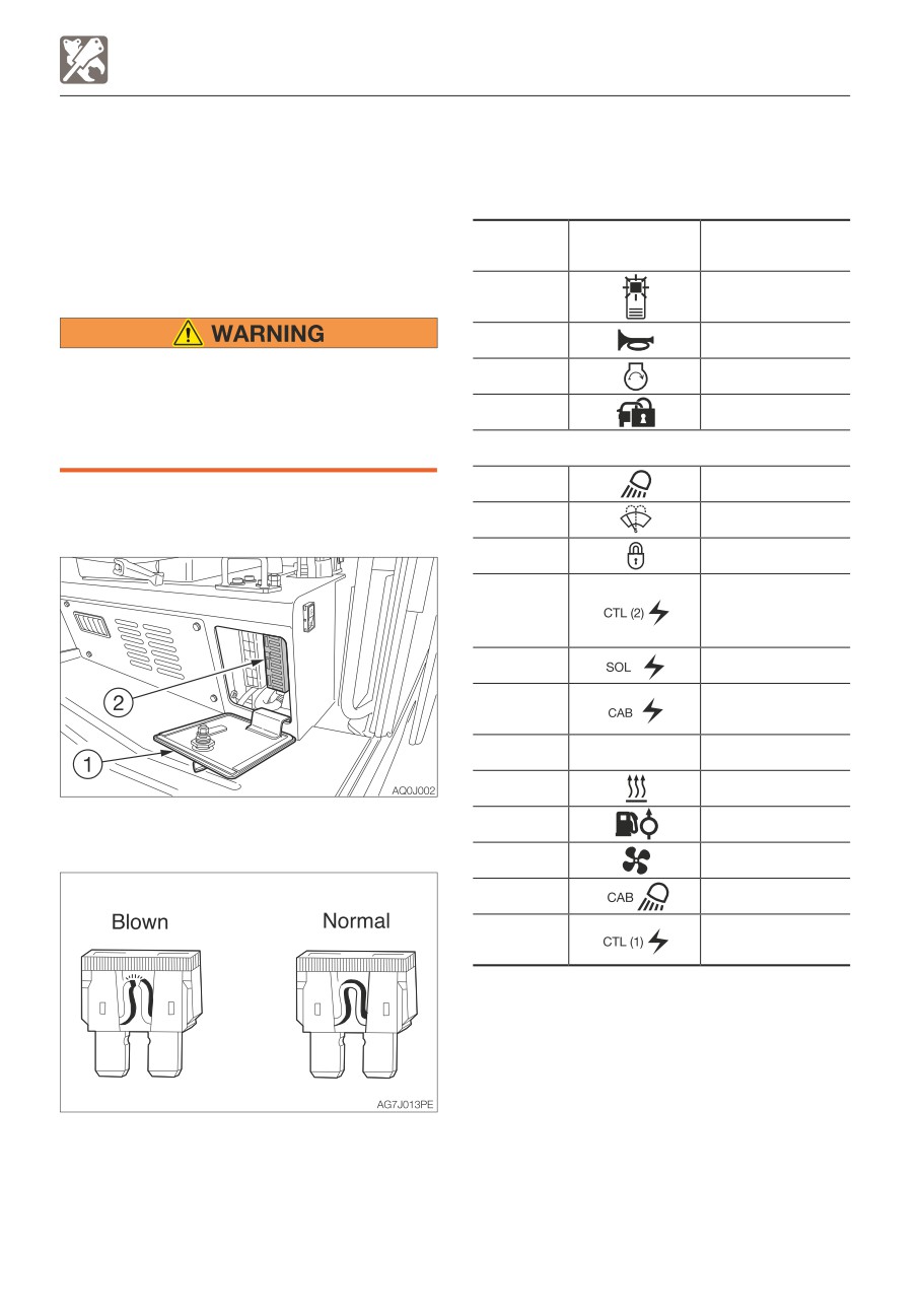
TRAVEL ALARM
The alarm sounds while the machine is
<Cab>
traveling and stops when the machine stops
traveling.
Protected
If the alarm does not sound when the
Capacity
Symbol
circuit
machine travels, the fuse may be blown.
Inspect the fuses.
5A
Switch lighting
10A
Horn
If the fuse blows again soon after
5A
Starter switch
replacement, then the electric system is
likely faulty. It may pose a fire hazard if
10A
Immobilizer
not properly repaired. Contact your sales
or service dealer for advice.
20A
Light
1. Turn the starter key to the OFF position to
stop the engine.
10A
Wiper
20A
Lever lock
Controller power
10A
supply (2),
Travel alarm
10A
Solenoid
Cab interior
20A
power supply
25A
OPT
Option
10A
Heater
2. Open the fuse box cover (1).
10A
Feed pump
3. Check for any blown fuses (2).
30A
Blower motor
20A
Cab light
Controller power
20A
supply (1)
4. If a fuse is blown, replace it with a spare
fuse of the same capacity.
8-8
OPTIONS
TRAVEL ALARM
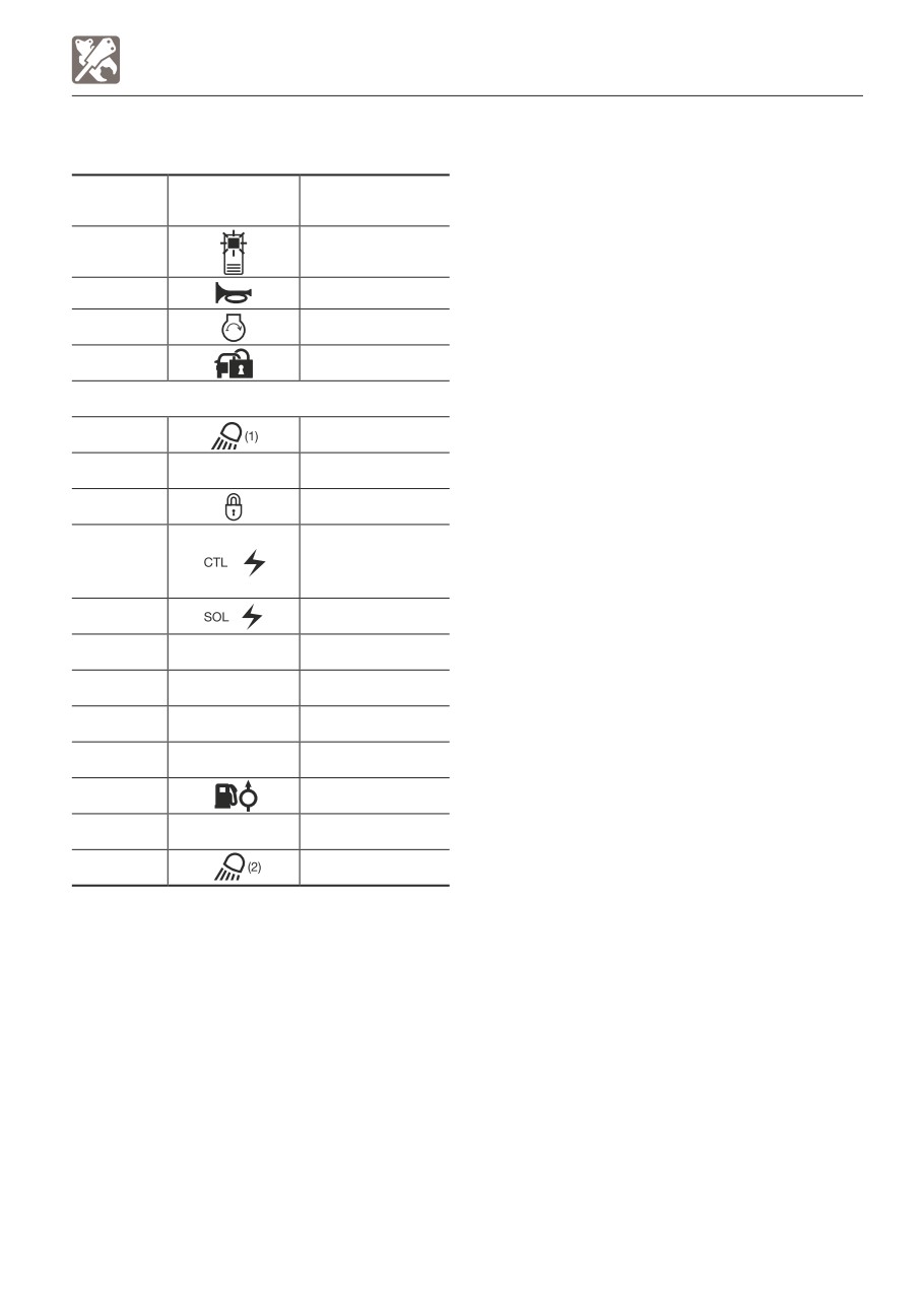
<Canopy>
Protected
Capacity
Symbol
circuit
5A
Switch lighting
10A
Horn
5A
Starter switch
10A
Immobilizer
20A
Light (1)
20A
Lever lock
Controller power
15A
supply,
Travel alarm
25A
Solenoid
20A
OPT (1)
Option (1)
25A
OPT (2)
Option (2)
10A
Feed pump
15A
Light (2)
8-9

OPTIONS
OPTIONAL EQUIPMENT MASS
OPTIONAL EQUIPMENT MASS
OPTION
Steel crawler (Including shoe guide)
83 (183)
Angle blade
89 (196)
Long arm
9 (20)
Roof guard (Level II: ISO 10262)
47 (104)
Front guard (Level II: ISO 10262)
42 (91)
Units: kg (lb)
*: Mass of optional equipment is added to the standard machine mass.
*: This table only contains the optional equipment of 10kg (20lb) or more in mass.
8-10
OPTIONS
BIODEGRADABLE OIL
4. Bleed the air from the hydraulic oil system.
BIODEGRADABLE OIL
5. Operate the hydraulic devices for 30
Biodegradable oil is a new type of hydraulic
minutes.
oil that is decomposed into carbon dioxide
6. Drain the biodegradable oil from the tank
and water by microorganisms in the soil and
and cylinders.
water. It is highly safe for living organisms
7. Replace the hydraulic oil return filter with a
and offers advantages in term of
new filter.
environmental protection.
8. Repeat steps 3 and 4.
• Recommended biodegradable oil: Mobile
9. Operate the hydraulic devices for 30
EAL Envirosyn 46H (an ester synthetic oil).
minutes.
When replacing the hydraulic oil with
10. Drain the biodegradable oil from the tank
biodegradable oil, use the above or an
and cylinders.
equivalent oil.
11. Repeat steps 3 and 4.
Note that other oils, even other brands of
12. Operate the hydraulic devices for 1 hour.
ester synthetic oils, may damage O-rings,
13. Drain the biodegradable oil from the tank
packings and seals. Takeuchi products
and cylinders.
shipped with the optional biodegradable oil
14. Replace the return filter with a new filter.
are shipped with the above brand of oil.
15. Repeat steps 3 and 4.
• When switching from a mineral oil to a
16. Operate the hydraulic devices, then
biodegradable oil, the parking brake torque
check for oil leakage.
decreases by about 30%.
There is no need to flush the hydraulic oil
system when switching from biodegradable
to mineral hydraulic oil.
REPLACING THE HYDRAULIC OIL WITH
BIODEGRADABLE OIL
Mixing mineral oil with biodegradable oil will
result in a decrease of the hydraulic oil’s
performance as well as a decrease in
biodegradability and safety. The hydraulic oil
system must be flushed as described below
before supplying the biodegradable oil. This
operation is dangerous and requires
experience. Have it performed by a Takeuchi
sales or service outlet.
Flushing
To be performed by a Takeuchi sales or
service outlet
1. Drain the hydraulic oil (mineral oil) from the
hydraulic oil tank and clean the inside of
the tank and suction strainer.
Refer to “Replacing the hydraulic oil and
cleaning the suction strainer”.
2. Remove the cylinder hoses and drain the
hydraulic oil (mineral oil) from inside the
cylinders.
3. Supply new biodegradable oil to the
hydraulic oil tank.
8-11
OPTIONS
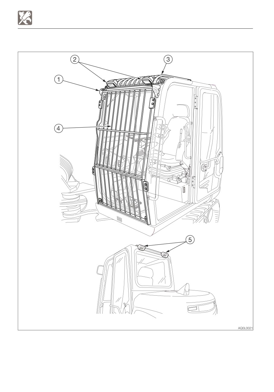
CAB OPTIONS
CAB OPTIONS
1. Rain guard
2. Front light
3. Roof guard (Level II: ISO 10262)
4. Front guard (Level II: ISO 10262)
5. Rear light
8-12
OPTIONS
ANGLE DOZER BLADE
ANGLE DOZER BLADE
• Do not press the float button while the
machine is raised by the dozer blade.
Doing so will cause the machine to fall.
If you must work beneath the raised
machine, always use a secure support
to keep the machine raised.
• Do not press the float button while the
dozer blade is raised. Doing so will
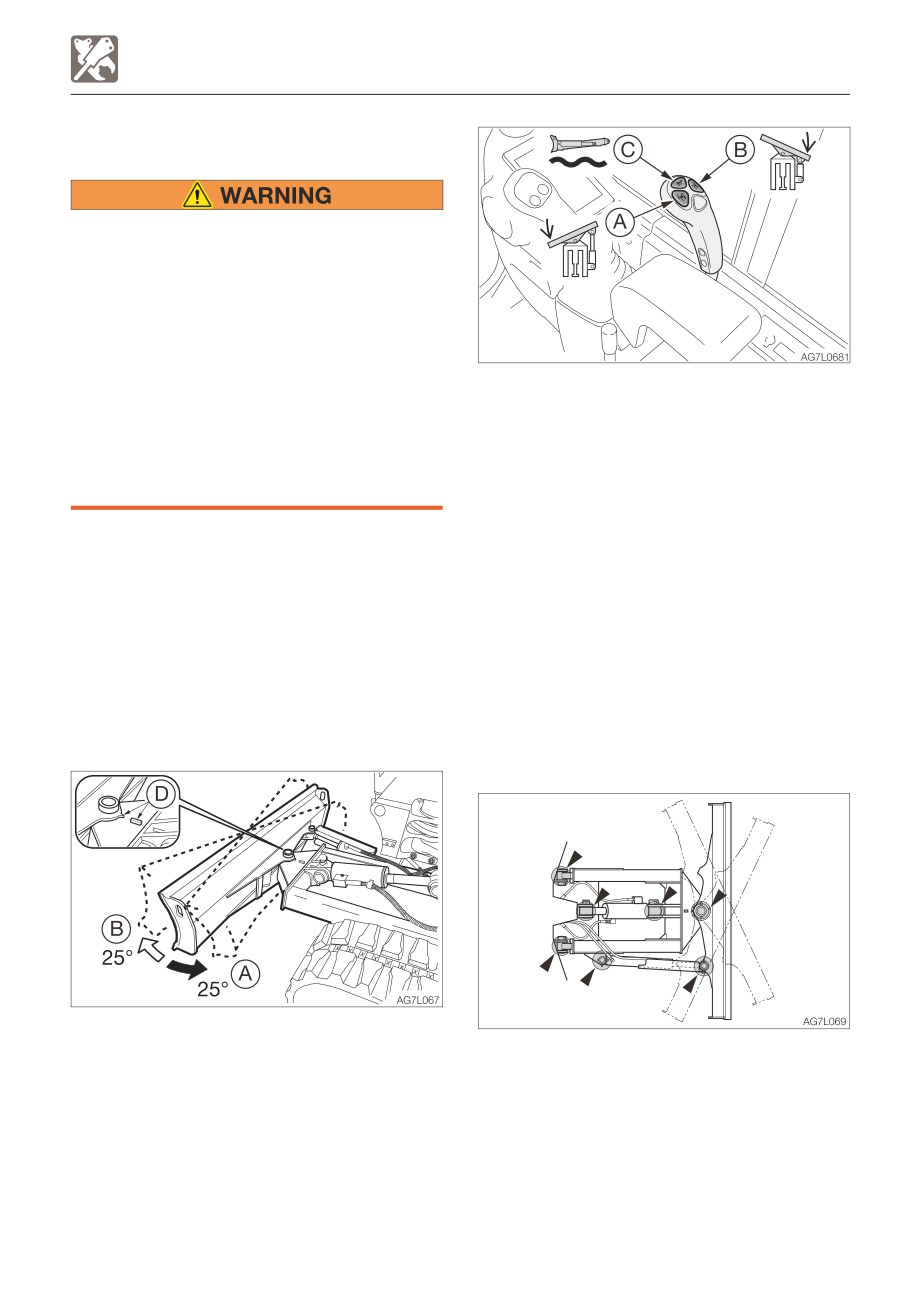
Button (A)
Left angle (0 to 25°)
cause the dozer blade to fall. Lower the
Button (B)
Right angle (0 to 25°)
dozer blade to the ground before
The dozer blade angle is
pressing the float button.
increased/decreased between
• Do not travel forward while the dozer
0 and 25° as long as the
blade is in the float mode.
button is pressed.
To position the dozer blade at
IMPORTANT: Do not raise the machine by
a right angle, align the
using the angled dozer blade. Or, the
matching marks (D) as shown
dozer blade may be damaged due to the
in the figure.
load concentrated onto a point on the
dozer blade.
Float operation
This dozer blade can be angled (to 25° right
Button (C)
Float mode
or left). Also, it can be used in the float
To cancel the float mode,
mode.
press the button again.
Angle operation
Daily inspection (every 10 hours)
Lubricating
1. Lower the working equipment to the
ground and stop the engine.
2. Use the grease gun to lubricate the grease
fitting.
3. Wipe off the excess grease.
8-13
OPTIONS
ANGLE DOZER BLADE
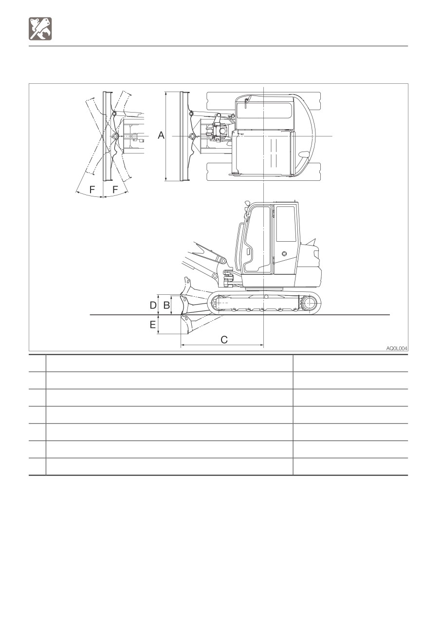
SPECIFICATIONS
Item
Rubber crawlers
A
Dozer blade width
1450 (57.1)
B
Dozer blade height
355 (14)
C
Dozer blade distance to axis of rotation
1480 (58.3)
D
Dozer blade maximum lifting
370 (14.5)
E
Dozer blade maximum lowering
325 (12.9)
F
Angle degree (Left/Right)
25°
Unit: mm (inch)
8-14
First Published August 2014
No.43521
Second Published December 2014
OPERATOR’S MANUAL
TB230 Mini excavator
Edited and issued by TAKEUCHI MFG. CO., LTD.
Printed in Japan by STATION M Co., Ltd.
CALIFORNIA
PROPOSITION 65 WARNING
Diesel engine exhaust and some of its constituents are known to the State of California
to cause cancer, birth defects, and other reproductive harm.
Battery posts, terminals and related accessories contain lead and lead compounds,
chemicals known to the State of California to cause cancer and birth defects or other
reproductive harm. Wash hands after handling battery.
EC-CONFORMITY CERTIFICATE
We herewith declare that following named machine, based on its conception and design
and in the form brought into service is in accordance with the relevant, basic safety and
health requirements of the following EC directives. In case of any alteration of the
machine not coordinated with us, this certificate loses its validity.
Designation of the machine Compact Excavator
Manufacturer
TAKEUCHI MFG. CO., LTD
205 Uwadaira, Sakaki-machi, Hanishina-gun, Nagano
389-0605, Japan
Model
TB230
Engine type
3TNV88F-EPTB
Engine power
18.2 kW @ 2400 rpm
The machine is in accordance with the requirements of EC regulations:
1) Machine directive 2006/42/EC and appendix
2) Electromagnetic compatibility-regulation 2004/108/EC and appendix
3) Noise directive 2000/14/EC (Evaluation procedure according to appendix VI),
2005/88/EC and appendices.
4) Regulations on engine emissions: 2004/26/EC and appendices.
Harmonized norms: EN474-1:2006+A1:2009, EN474-5:2006+A2:2012.
Complier of the technical files:
Adam Geiss
Oliver Scharschmidt
Wilhelm Schafer Gmbh
68307 Manheim-Sandhofen GERMANY
Issued in Sakaki, Japan
Akio Takeuchi, President