Takeuchi Mini Excavator TB215R (No.215000003~). Operator's Manual - page 18
 

  Index      Manuals     Takeuchi Mini Excavator TB215R (No.215000003~). Operator's Manual


Search            copyright infringement  


Content      ..     16      17      18      19     ..


Takeuchi Mini Excavator TB215R (No.215000003~). Operator's Manual - page 18


1

5

Slew mOTOr

TroubleshooTing

5n0AX00

sleW moTor

Slew mOTOr

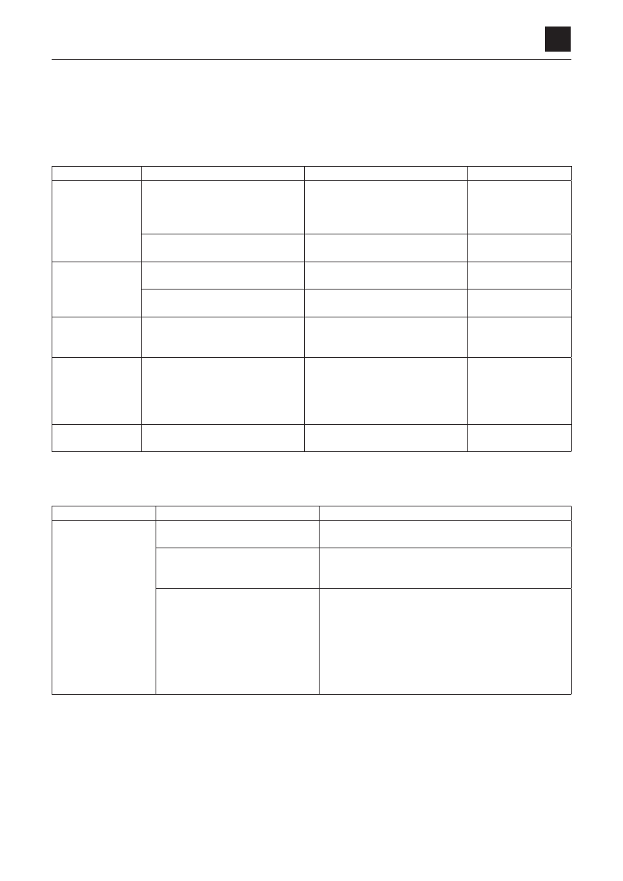
If you notice that the noise or heat becomes unusually high, it is likely that there is a fault in the machine. If it occurs, stop 

the machine immediately and try to locate the faulty section.

The table below shows the cause of the general problem and action to be taken when such problem occurs in the hydraulic 

circuits.

hydraulic motor, brake valve

symptoms

how/Where?

major causes

remedies

motor fails to start

• No  pressure  at  the  motor’s  inlet 

port

• Set  pressure  of  relief  valve  is  too 

low

• Pump faulty
• Control valve faulty

• Set correctly

• Repair or replace
• Repair or replace

• There  is  pressure  at  the  motor’s 

inlet port

• Load is too heavy
• hydraulic motor is faulty

• Reduce the load
• Repair or replace

motor  does  not 
speed up

• Pump discharge is insufficient

• Too much drain from the pump

• Repair  or  replace 

the pump

• Functional problem of the motor

• Drop in the motor’s volumetric ef

-

ficiency 

• Replace the motor

Direction  of  rota-
tion is incorrect

• Piping
• Motor valve timing

• Piping is incorrectly connected.
• Motor valve timing is incorrect.

• Correct the piping.
• Set the valve timing 

correctly

Oil is leaking

• Leaking from the mating surface

• Bolts are loose
• O-ring is faulty
• Mating surface is scratched

• Retighten the bolts
• Replace
• Repair  the  surface 

with a grindstone or 

sand paper

motor  produces 
abnormal noise

• Noise in the piping

• Piping support is faulty

• Clamp the piping

parking brake

symptoms

major causes

remedies

cannot  release  the 
brake.  brake  force  is 

weak.  Brake  drags, 

produces noise, heat

• Release pressure PB is not gener

-

ated or, supply pressure is low.

• Set the release pressure PB as specified.

• Valve does not operate due to high 

drain pressure

• Check the drain circuit for clogging and repair. If drain 

from the motor is too large, check and repair the mo

-

tor.

brake piston does not operate

• O-rings are abnormally worn
• Sliding  parts  are  worn  or  dam

-

aged

• Foreign matter is caught

• Wear-resistant material is worn
• A spring is broken

• Replace
• Repair or replace the sliding parts

• Remove  the  foreign  matter  and  repair  or  replace  the 

sliding parts

• Replace
• Replace

MONOCHROME LCD CLUSTER PANEL DISPLAY AND LCD SPECIFICATIONS (WITHOUT A CAN)

1

6

6S3AY00

Monochrome LCD Cluster

Panel Display and LCD Specifications

(Without a CAN)

MONOCHROME LCD CLUSTER PANEL DISPLAY AND LCD SPECIFICATIONS (WITHOUT A CAN)

CONTENTS

6

2

CONTENTS

6S3AY00

CONTENTS

1

Contents

2

Normal Panel Display/LCD Screen

3

Panel Display: Water Temperature Gauge

4

Panel Display: Fuel Gauge

5

Panel Display: Function/Warning Lamps

6

Normal Screen

7

Main Menu Screen

8

Data Selection Screen

9

Data Screen (TRIP METER)

10

Data Screen (WATER TEMP.)

11

Settings Selection Screen

12

Setting Screen (CLOCK)

13

Setting Screen (ALARM)-1

14

Setting Screen (ALARM)-2

15

Setting Screen (CONTRAST ADJ.)

MONOCHROME LCD CLUSTER PANEL DISPLAY AND LCD SPECIFICATIONS (WITHOUT A CAN)

NORMAL PANEL DISPLAY/LCD SCREEN

3

6

NORMAL PANEL DISPLAY/LCD SCREEN

6S3AY00

NORMAL PANEL DISPLAY/LCD SCREEN

Off States for Function and 
Warning Display Indicators

On States for Function and 

Warning Display Indicators

Panel Display

1

Water temperature 
gauge

2

Fuel gauge

LCD

1

Hour meter

2

Clock

3

Switch function display

Panel Display

1

Water temperature gauge

2

Fuel gauge

3

Function/warning lamps

Water temperature warning
light

Charge warning light

2nd speed travel light

Engine oil warning light

Glow light

Low fuel level warning light

System warning light

LCD

1

Hour meter

2

Clock

3

Switch function display

4

Function/warning display

High-altitude mode light

3rd S pressure warning light

Alarm light

* If there is no CAN present, the lights turn ON for 1.2 s in this state for a lamp check test.

All lights on the LCD screen also turn ON for 1.2 s at this time. The alarm buzzer also
sounds for 1.2 s.
The current time displays on the clock display during the lamp check. (The time does
not display as 12:34, in other words, unless that happens to be the current time.)

MONOCHROME LCD CLUSTER PANEL DISPLAY AND LCD SPECIFICATIONS (WITHOUT A CAN)

PANEL DISPLAY: WATER TEMPERATURE GAUGE

6

4

PANEL DISPLAY: WATER TEMPERATURE GAUGE

6S3AY00

PANEL DISPLAY: WATER TEMPERATURE GAUGE

Resistance characteristics

Temp.

[°C (°F)]

Resistance

[k

Ω

]

-30 (-22)

25.4

-20 (-4)

15.04

-10 (14)

9.16

0 (32)

5.74

5 (41)

4.72

10 (50)

3.7

20 (68)

2.45

30 (86)

1.66

40 (104)

1.15

50 (122)

0.811

60 (140)

0.584

70 (158)

0.428

80 (176)

0.318

90 (194)

0.24

95 (203)

0.2118

100 (212)

0.1836

105 (221)

0.1627

110 (230)

0.1417

120 (248)

0.1108

80°C 

t < 95°C

95°C 

t < 105°C

105°C

t <110°C

110°C 

t

t < 50°C

50°C 

t < 60°C

60°C 

t < 70°C

70°C 

t < 80°C

* Average values are used for the output values. (The average amount of movement over a

span of 5 seconds measured in 100-ms intervals.)

* Allowable error: ±5% (Allowable error for the water temperature gauge sensor parts listed

separately)

MONOCHROME LCD CLUSTER PANEL DISPLAY AND LCD SPECIFICATIONS (WITHOUT A CAN)

PANEL DISPLAY: FUEL GAUGE

5

6

PANEL DISPLAY: FUEL GAUGE

6S3AY00

PANEL DISPLAY: FUEL GAUGE

Resistance characteristics

* Average values are used for the output values. (The average amount of movement over a span of 120 seconds mea-

sured in 100-ms intervals.)

Float position

FULL

3/4

1/2

1/4

EMPTY

Resistance (

Ω

)

10

17.7

(38)

61.7

90

Allowable error (

Ω

)

0

-4

+10

0

r < 12.8

 Ω

12.8 

Ω


<17.7 

Ω

17.7 

Ω


< 27.9 

Ω

27.9 

Ω


< 38 

Ω

38

 Ω


< 49.9 

Ω

49.9

 Ω


< 61.7 

Ω

61.7 

Ω


< 75.9 

Ω

75.9 

Ω


< 90 

Ω

90 

Ω


r

* Allowable error: ±5%

(Allowable error for the fuel gauge float parts list-
ed separately)

MONOCHROME LCD CLUSTER PANEL DISPLAY AND LCD SPECIFICATIONS (WITHOUT A CAN)

PANEL DISPLAY: FUNCTION/WARNING LAMPS

6

6

PANEL DISPLAY: FUNCTION/WARNING LAMPS

6S3AY00

PANEL DISPLAY: FUNCTION/WARNING LAMPS

Overheating warning light

Lamp ON conditions: Flashes when the temperature rises above 110°C (230°F)(Resistance: 0.1417 k

Ω

).

Turns on solid for 0.5 s then goes out for 0.5 s and repeats in a flashing pattern.

Engine oil pressure warning light

Flashes when the oil pressure switch is ON (while set to LO).
Turns on solid for 0.5 s then goes out for 0.5 s and repeats in a flashing pattern.

Charge warning light

Lamp ON conditions: Flashes when the voltage at the alternator input terminal is reading below +3 V.
Turns on solid for 0.5 s then goes out for 0.5 s and repeats in a flashing pattern.

2nd speed travel light

Toggles from OFF to ON (or ON to OFF) along with the 2nd speed travel relay when the 2nd speed travel 

switch is turned from OFF to ON to OFF (by flip-flop operation).

Chattering check: 20 ms

Glow lamp

Lamp ON conditions: Turns ON for 3 s when ACC is ON (Turns ON when the glow relay is ON; turns OFF if 

a Start signal is received within 3 s of being ON).

(Turns ON when the glow relay is ON, OFF when the glow relay is OFF, and OFF if a Start signal is received 

within 3 s of being ON.)

Low fuel level warning light

Lamp ON conditions: Turns ON if the resistance increases to 75.9 

Ω

 or higher.

System warning light

Lamp ON conditions: Flashes when one of the Overheating, Engine oil warning, or Charge warning lights is 

turned ON.

Turns on solid for 0.5 s then goes out for 0.5 s and repeats in a flashing pattern.

* If any one or more of the overheating warning light, engine oil pressure warning light, or charge warning light turns ON, chattering is determined to have occurred for 1.5

s. After 1.5 s passes, the warning light begins to flash and the buzzer to sound (ON for 0.5 s and then OFF for 0.5 s and so on in a repeating pattern). If the system is able
to return to a normal state, the warning light and buzzer turn OFF after 1.5 s.

* If both the charge warning light and engine oil pressure warning light are in the abnormal state and the engine enters a shut-off state, the buzzer only will turn OFF after

10 s lapses, even if the abnormal state continues.

MONOCHROME LCD CLUSTER PANEL DISPLAY AND LCD SPECIFICATIONS (WITHOUT A CAN)

NORMAL SCREEN

7

6

NORMAL SCREEN

6S3AY00

NORMAL SCREEN

1

Hour meter

The hour meter begins counting when the input terminal voltages of the alternator and trip meter rise above +3 V.

Pressing and holding down Button [2] for 2 seconds switches the display to the trip meter.
(Toggles in order of Hour meter to Trip 1 to Trip 2 to Trip 3 to Hour meter.)

Pressing and holding down Button [3] for 3 seconds resets the trip meter while it is displayed.

*

The hour meter displays right after ACC is turned ON.

2

Clock display

The clock displays as a 24-hour clock.

Refer to “Setting Screen (Clock)” for details on how to set the time.

3

Switch function display

The takt switch functions are displayed.

The display changes on the Normal screen, Setting screen, and Data screen.

In Normal screen mode: Pressing Button [1] for a short while 

 No function, Pressing and holding down Button [1]

for a long time 

 No function.

In Normal screen mode: Pressing Button [2] for a short while 

 Turns on the work light, Pressing and holding down

Button [2] for 2 seconds 

 Toggles the display to the trip meter.

In Normal screen mode: Pressing Button [3] for a short while 

 Moves the display to the Main menu, Pressing and

holding down Button [3] for 3 seconds 

 Resets the trip meter.

4

3rd S pressure warning light

The pressure switch turns OFF, and the icon displays when the 3rd S pressure drops (The switch turns ON and the
icon OFF when the pressure goes up.)

5

High-altitude mode light

The icon displays when the high-altitude switch is turned ON.

6

Alarm light

The icon displays while the alarm function is turned ON.

Refer to “Setting Screen (Alarm)” for details on how to set the alarm.

A buzzer sounds for 30 s while the alarm is ON (During the first 15 s, the buzzer turns on and off repeatedly for 0.5 s
each way; during the last 15 s, it turns on and off repeatedly for 0.3 s each way.

The icon flashes (ON for 0.5 s, OFF for 0.5 s, and so on) while the buzzer is sounding.

Pressing Button [1] for a short amount of time while the alarm is ON stops the buzzer.

The work light toggles between ON
and OFF with each quick press of
Button [2]. The light relay also tog-
gles ON/OFF at this time.

MONOCHROME LCD CLUSTER PANEL DISPLAY AND LCD SPECIFICATIONS (WITHOUT A CAN)

MAIN MENU SCREEN

6

8

MAIN MENU SCREEN

6S3AY00

MAIN MENU SCREEN

• Pressing Button [3] on the Normal screen for a short while moves the display to the Main Menu screen.
• Pressing Button [3] on the Main Menu screen for a short while moves the display to the Normal screen.
• Pressing Button [2] on the Main Menu screen for a short while moves the bar to the next option.
• Pressing Button [1] while [DATA] is highlighted moves the display to the Data Selection screen.
• Pressing Button [1] while [SETTING] is highlighted moves the display to the Settings Selection screen.

Normal Screen

Main Menu Screen

MONOCHROME LCD CLUSTER PANEL DISPLAY AND LCD SPECIFICATIONS (WITHOUT A CAN)

DATA SELECTION SCREEN

9

6

DATA SELECTION SCREEN

6S3AY00

DATA SELECTION SCREEN

• Pressing Button [1] while [DATA] is highlighted moves the display to the Data Selection screen.
• Pressing Button [3] on the Data Selection screen for a short while moves the display to the Main Menu screen.
• Pressing Button [2] on the Data Selection screen for a short while moves the bar to the next option.
• Pressing Button [1] on the Data Selection screen for a short while moves the display to the Data screen for the highlighted option.

Main Menu Screen

Data Selection Screen

MONOCHROME LCD CLUSTER PANEL DISPLAY AND LCD SPECIFICATIONS (WITHOUT A CAN)

DATA SCREEN (TRIP METER)

6

10

DATA SCREEN (TRIP METER)

6S3AY00

DATA SCREEN (TRIP METER)

• Pressing Button [1] for a short amount of time while [TRIP METER] is highlighted moves the display to the DATA screen (TRIP METER).
• The screen displays the trip meter values. (0 to 99999)
• If there is no CAN, the count for the trip meter begins when the input terminal voltage of the alternator rises above +3 V, as in the case of the hour meter.
• Pressing Button [2] on the DATA screen (TRIP METER) for a short while moves the bar to the next option. The setting value for the highlighted option flashes.
• Pressing and holding down Button [1] on the DATA screen (TRIP METER) for 5 seconds resets the value of the highlighted trip meter back to 0.
• The reset is confirmed when the value is reset. No particular changes occur with the displayed screen or position of the highlighting bar, which remain as is.
• The data is saved to the EEPROM when the value is reset. (Data is saved when ACC is turned OFF.) 
• Pressing Button [3] on the DATA screen for a short while moves the display to the Data Selection screen.

Data Selection Screen

DATA Screen (TRIP METER)

MONOCHROME LCD CLUSTER PANEL DISPLAY AND LCD SPECIFICATIONS (WITHOUT A CAN)

DATA SCREEN (WATER TEMP.)

11

6

DATA SCREEN (WATER TEMP.)

6S3AY00

DATA SCREEN (WATER TEMP.)

Resistance characteristics

Temp.

[°C (°F)]

Resistance

[k

Ω

]

-30 (-22)

25.4

-20 (-4)

15.04

-10 (14)

9.16

0 (32)

5.74

10 (50)

3.7

20 (68)

2.45

30 (86)

1.66

40 (104)

1.15

50 (122)

0.811

60 (140)

0.584

70 (158)

0.428

80 (176)

0.318

90 (194)

0.24

100 (212)

0.1836

110 (230)

0.1417

120 (248)

0.1108

• Pressing Button [1] while [WATER TEMP.] is highlighted moves the display to the DATA screen (WATER TEMP.).
• Pressing Button [3] on the Data screen for a short while moves the display to the Data Selection screen.
• If there is no CAN present, the water temperature starts being calculated using resistance values arising when a voltage is applied.
• The water temperature is displayed in both degrees Celsius and degrees Fahrenheit.

Data Selection Screen

DATA Screen (WATER TEMP.)

MONOCHROME LCD CLUSTER PANEL DISPLAY AND LCD SPECIFICATIONS (WITHOUT A CAN)

SETTINGS SELECTION SCREEN

6

12

SETTINGS SELECTION SCREEN

6S3AY00

SETTINGS SELECTION SCREEN

• Pressing Button [1] while [SETTING] is highlighted moves the display to the Settings Selection screen.
• Pressing Button [3] on the Settings Selection screen for a short while moves the display to the Main Menu screen.
• Pressing Button [2] on the Settings Selection screen for a short while moves the bar to the next option.
• Pressing Button [1] on the Data Selection screen for a short while moves the display to the Setting screen for the highlighted option.

Main Menu Screen

Settings Selection Screen

MONOCHROME LCD CLUSTER PANEL DISPLAY AND LCD SPECIFICATIONS (WITHOUT A CAN)

SETTING SCREEN (CLOCK)

13

6

SETTING SCREEN (CLOCK)

6S3AY00

SETTING SCREEN (CLOCK)

• Pressing Button [1] for a short amount of time while [CLOCK] is highlighted moves the display to the Setting screen (Clock Settings).
• Pressing Button [1] on the Setting screen for a short while moves the bar to the next option. The setting value for the highlighted option flashes. (Displaying in the normal

color for 0.5 s and then in the inverted color for 0.5 s and so on.)

• Pressing Button [2] on the Setting screen for a short while causes the setting value of the highlighted option to increase. Pressing and holding down Button [2] for 1 second

causes the setting value of the highlighted option to increase at high speed.

• Setting range for hours: 1 to 24 (Toggles from 1 to 2 to...24 and back to 1, where it starts start over). Setting range for minutes: 00 to 59 (Toggles from 00 to 01 to...59 and

back to 00, and back to 1, where it starts over)

• Pressing Button [3] on the Setting screen for a short while moves the display to the Settings Selection screen. (Any changes made to the settings will be canceled.)
• Pressing and holding down Button [1] on the Setting screen for 2 seconds confirms the setting changes and moves the display to the Settings Selection screen.

Settings Selection Screen

Setting Screen (CLOCK)

MONOCHROME LCD CLUSTER PANEL DISPLAY AND LCD SPECIFICATIONS (WITHOUT A CAN)

SETTING SCREEN (ALARM)-1

6

14

SETTING SCREEN (ALARM)-1

6S3AY00

SETTING SCREEN (ALARM)-1

Settings Selection Screen

Setting Screen (ALARM)

• Pressing Button [1] for a short amount of time while [ALARM] is highlighted moves the display to the 

Setting screen (Alarm Settings).

• Pressing Button [2] on the Setting screen for a short while moves the bar to the next option.
• Pressing Button [1] on the Setting screen for a short while toggles the checkbox to the left of the 

highlighted option between being checked and not checked.

• Pressing and holding down Button [1] on the Setting screen for 2 seconds completes configuration of the alarm and moves the display to the Settings Selection screen.

The ALARM icon on the Normal screen (p. 1) turns ON.

• Pressing Button [3] on the Setting screen for a short while moves the display to the Settings Selection screen. (Any changes made to the settings will be canceled.)
• Once the alarm has been turned ON (the checkbox has been checked), it will remain enabled until the checkbox is unchecked.
• The alarm configuration settings (including the time) save to memory when ACC is turned OFF, and the stored settings are then loaded the next time that ACC is turned ON.

MONOCHROME LCD CLUSTER PANEL DISPLAY AND LCD SPECIFICATIONS (WITHOUT A CAN)

SETTING SCREEN (ALARM)-2

15

6

SETTING SCREEN (ALARM)-2

6S3AY00

SETTING SCREEN (ALARM)-2

Setting Screen (ALARM)

• Pressing Button [2] on the Setting screen for a short while moves the bar to 

the next option.

• Pressing and holding down Button [2] on the Setting screen for 3 seconds moves the bar to 

the ALARM TIME screen. Pressing Button [2] on that screen for a short while causes the numerical value 
for the highlighted option to increase. Pressing and holding down Button [2] for 1 second causes the setting value of the highlighted option to increase at high speed.

• Setting range for hours: 1 to 24 (Toggles from 1 to 2 to...24 and back to 1, where it starts start over). Setting range for minutes: 00 to 59 (Toggles from 00 to 01 to...59 and

back to 00, and back to 1, where it starts over)

• Pressing Button [1] for a short while under the time settings option for ALARM moves the bar to the next option. The setting value for the highlighted option flashes.
• Pressing and holding down Button [1] for 2 seconds completes configuration of the alarm and moves the display to the Settings Selection screen.
• Pressing Button [3] on the Setting screen for a short while moves the display to the Settings Selection screen. (Any changes made to the settings will be canceled.)

Settings Sele

ct

ion Screen

MONOCHROME LCD CLUSTER PANEL DISPLAY AND LCD SPECIFICATIONS (WITHOUT A CAN)

SETTING SCREEN (CONTRAST ADJ.)

6

16

SETTING SCREEN (CONTRAST ADJ.)

6S3AY00

SETTING SCREEN (CONTRAST ADJ.)

Settings Selection Screen

Setting Screen (CONTRAST ADJ.)

• Pressing Button [1] for a short amount of time while [CONTRAST] is highlighted moves the display to the Setting screen (CONTRAST ADJ.).
• Pressing Button [2] on the Setting screen for a short while increases the setting value of the highlighted option. Pressing and holding down Button [2] for 1 second causes

the setting value of the highlighted option to increase at high speed.


• The contrast changes as the setting value of the bar increases.
• The contrast can be set to any of the 40 different setting levels available.
• Pressing Button [3] on the Setting screen for a short while moves the display to the Settings Selection screen. (Any changes made to the settings will be canceled.)
• Pressing and holding down Button [1] on the Setting screen for 3 seconds confirms the setting changes and moves the display to the Settings Selection screen.
• The confirmed setting values are saved to the EEPROM when the ACC is turned OFF and enabled until the next time the contrast is adjusted.


Content      ..     16      17      18      19     ..