SANY Crawler Hydraulic Excavator SY195C9, SY205C9, SY215C9, SY225C9. Service Manual - page 29
 

  Index      Manuals     SANY Crawler Hydraulic Excavator SY195C9, SY205C9, SY215C9, SY225C9. Service Manual (2013)


Search            copyright infringement  


Content      ..     27      28      29      30     ..


SANY Crawler Hydraulic Excavator SY195C9, SY205C9, SY215C9, SY225C9. Service Manual - page 29


7-88

Troubleshooting

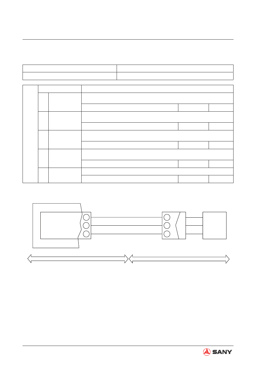
E-21  Incorrect bucket-curl pilot pressure reading

Trouble

Bucket-curl pilot pressure reading is incorrect. 

Related information

Possible causes and standard value in normal 

state

Cause

Standard value in normal state/Remarks on troubleshooting

1

Failure of 5V 

power supply

 Turn engine start switch to OFF position. Then, keep it at ON position to
perform troubleshooting.

Between CN-124M 

 and 

Voltage

About 5V

2

Open circuit of 

signal wire

 Turn engine start switch to OFF position. Keep it at OFF position to per-
form troubleshooting.

Between CN-124M 

 and controller pin 69 

Resistance

Ω

3

Short circuit of 

signal wire

 Turn engine start switch to OFF position. Keep it at OFF position to per-
form troubleshooting.

Between CN-124M 

 and ground

Resistance

2M 

Ω

4

Failure of sen-

sor

Turn engine start switch to OFF position. Then, keep it at ON position to
perform troubleshooting.

Between CN-124M 

 and ground

Voltage

0.5V~ 4.5V

5

CN-124M

DF-3

2

3

1

75

55

69

ZX215-1005112

5V

CHASSIS HARNESS

CAB

SIGNAL

GND WIRE

CONTROLLER

SENSOR 5V

SENSOR GND WIRE

BUCKET CURL
PRESS SENSOR

BUCKET CURL

PRESS SENSOR

7-89

Troubleshooting

E-22  Incorrect bucket-dump pilot pressure reading

Trouble

Bucket-dump pilot pressure reading is incorrect. 

Related information

Possible causes and standard value in normal 

state

Cause

Standard value in normal state/Remarks on troubleshooting

1

Failure of 5V 

power supply

 Turn engine start switch to OFF position. Then, keep it at ON position to
perform troubleshooting. 

Between CN-127M 

 and 

Voltage

About 5V

2

Open circuit of 

signal wire

 Turn engine start switch to OFF position. Keep it at OFF position to per-
form troubleshooting. 

Between CN-127M 

 and controller pin 50 

Resistance

Ω

3

Short circuit of 

signal wire

 Turn engine start switch to OFF position. Keep it at OFF position to per-
form troubleshooting. 

Between CN-127M 

 and ground

Resistance

2M 

Ω

4

Failure of sensor

Turn engine start switch to OFF position. Then, keep it at ON position to
perform troubleshooting. 

Between CN-127M 

 and ground

Voltage

0.5V~ 4.5V

5

CN-127M

DF-3

2

3

1

75

55

50

ZX215-1005113

5V

CHASSIS HARNESS

CAB

SIGNAL

GND WIRE

CONTROLLER

SENSOR 5V

SENSOR GND WIRE

BUCKET DUMP
PRESS SENSOR

BUCKET DUMP

PRESS SENSOR

7-90

Troubleshooting

E-23  Incorrect swing pilot pressure reading

Trouble

Swing pilot pressure reading is incorrect. 

Related information

Possible causes and standard value in normal 

state

Cause

Standard value in normal state/Remarks on troubleshooting

1

Failure of 5V 

power supply

 Turn engine start switch to OFF position. Then, keep it at ON position
to perform troubleshooting. 

Between CN-123M 

 and 

Voltage

About 5V

2

Open circuit of 

signal wire

 Turn engine start switch to OFF position. Keep it at OFF position to per-
form troubleshooting. 

Between CN-123M 

 and controller pin 68 

Resistance

Ω

3

Short circuit of 

signal wire

 Turn engine start switch to OFF position. Keep it at OFF position to per-
form troubleshooting. 

Between CN-123M 

 and ground

Resistance

2M 

Ω

4

Failure of sensor

Turn engine start switch to OFF position. Then, keep it at ON position
to perform troubleshooting. 

Between CN-123M 

 and ground

Voltage

0.5V~ 4.5V

5

CN-123M

DF-3

5V

2

3

1

75

55

68

ZX215-1005114

CHASSIS HARNESS

CAB

SIGNAL

GND WIRE

CONTROLLER

SENSOR 5V

SENSOR GND WIRE

SWING PILOT 
PRESS SENSOR

SWING PILOT 

PRESS SENSOR

7-91

Troubleshooting

E-24  Incorrect left travel pilot pressure reading

Trouble

Left Travel Pilot Pressure Reading is incorrect. 

Related information

Possible causes and standard value in normal 

state

Cause

Standard value in normal state/Remarks on troubleshooting

1

Failure of 5V 

power supply

 Turn engine start switch to OFF position. Then, keep it at ON position to
perform troubleshooting. 

Between CN-120M 

 and 

Voltage

About 5V

2

Open circuit of 

signal wire

 Turn engine start switch to OFF position. Keep it at OFF position to per-
form troubleshooting. 

Between CN-120M 

 and controller pin 49 

Resistance

Ω

3

Short circuit of 

signal wire

 Turn engine start switch to OFF position. Keep it at OFF position to per-
form troubleshooting. 

Between CN-120M 

 and ground

Resistance

2M 

Ω

4

Failure of sensor

Turn engine start switch to OFF position. Then, keep it at ON position to
perform troubleshooting. 

Between CN-120M 

 and ground

Voltage

0.5V~ 4.5V

5

 CN-120M
DF-3

5V

2

3

1

75

55

49

ZX215-1005115

CHASSIS HARNESS

CAB

CONTROLLER

SENSOR 5V

SENSOR GND WIRE

LEFT TRAVEL PILOT 
PRESSURE SENSOR

SIGNAL

GND WIRE

LEFT TRAVEL PILOT 
PRESSURE SENSOR

7-92

Troubleshooting

E-25  Incorrect right travel pilot pressure reading

Trouble

Right travel pilot pressure reading is incorrect. 

Related information

Possible causes and standard value in normal 

state

Cause

Standard value in normal state/Remarks on troubleshooting

1

Failure of 5V 

power supply

 Turn engine start switch to OFF position. Then, keep it at ON position to
perform troubleshooting. 

Between CN-121M 

 and 

Voltage

About 5V

2

Open circuit of 

signal wire

 Turn engine start switch to OFF position. Keep it at OFF position to per-
form troubleshooting. 

Between CN-121M 

 and controller pin 67 

Resistance

Ω

3

Short circuit of 

signal wire

 Turn engine start switch to OFF position. Keep it at OFF position to per-
form troubleshooting. 

Between CN-121M 

 and ground

Resistance

2M 

Ω

4

Failure of sen-

sor

Turn engine start switch to OFF position. Then, keep it at ON position to
perform troubleshooting. 

Between CN-121M 

 and ground

Voltage

0.5V~ 4.5V

5

 CN-121M

DF-3

5V

2

3

1

75

55

67

ZX215-1005116

CHASSIS HARNESS

CAB

CONTROLLER

SENSOR 5V

SENSOR GND WIRE

RIGHT TRAVEL PILOT 
PRESSURE SENSOR

SIGNAL

GND WIRE

RIGHT TRAVEL PILOT 

PRESSURE SENSOR

7-93

Troubleshooting

7.7  

Troubleshooting of Hydraulic and Mechanical Systems (H - Mode)

A Schematic of hydraulic system and mechanical system ........................................................ 7-94
Information contained in troubleshooting table .......................................................................... 7-96
H-1  Work equipment speed slow, or swing and travel speeds slow ......................................... 7-97
H-2  Engine speed drops sharply or engine stalls ..................................................................... 7-98
H-3  Work equipment, swing, and travel systems do not work .................................................. 7-99
H-4  Abnormal noise in hydraulic pump ................................................................................... 7-100
H-5  Auto deceleration not functioning..................................................................................... 7-101
H-6  Boom speed slow ............................................................................................................ 7-102
H-7  Arm speed slow ............................................................................................................... 7-103
H-8  Bucket speed slow ........................................................................................................... 7-104
H-9  Work equipment cylinders no response in separate operation  ....................................... 7-105
H-10  Work equipment drifts excessively ................................................................................ 7-106
H-11  Work equipment moves sluggishly  ............................................................................... 7-108
H-12  Other work equipment moves while single oil circuit is relieved .................................... 7-108
H-13  Travel speed drops considerably while swinging and travelling .................................... 7-109
H-14  Machine deviates during travel ...................................................................................... 7-110
H-15  Travel speed is low .........................................................................................................7-111
H-16  Machine is not steered well or steering power is low..................................................... 7-112
H-17  Travel speed cannot be changed................................................................................... 7-113
H-18  Travel system fails (only at one side)............................................................................. 7-114
H-19  Swing operation fails...................................................................................................... 7-115
H-20  Swing acceleration poor or swing speed low ................................................................. 7-117
H-21  Upper structure overruns remarkably when it stops swinging ....................................... 7-119
H-22  Large shock is produced when upper structure stops swinging .................................... 7-120
H-23  High noise is produced when upper structure stops swinging ....................................... 7-120
H-24  Swing drift excessive ..................................................................................................... 7-121

7-94

Troubleshooting

 A Schematic of hydraulic system and mechanical system

15

16

14

13

1

2

3

4

12

11

10

9

8

7

6

5

P2

P1

19

17

20

18

1
2

3

REAR

FRONT

M

ZX225-1105039

PILOT VALVE - L

PILOT VALVE - TRAVEL

PILOT VALVE - R

IN

OUT

LEFT

RIGHT

LOWER

RAISE

BWD

FWD

CURL

DUMP

FWD

BWD

ARM

SWING

TRAVEL
(LEFT)

TRAVEL
(RIGHT)

BOOM

BUCKET

ACCUMULATOR

LOCK
(PILOT VALVE )

BUCKET CONFLUENCE

SWING PRIORITY

VARIABLE SPEED 
(TRAVEL)

BOOM PRIORITY

REGULATOR

SERVO

MECHANISM

REGULATOR

SERVO

MECHANISM

7-95

Troubleshooting

The system schematic is a simpli

fi

 ed hydraulic circuit schematic, which can be used as a ref-

erence to the hydraulic system and the mechanical system.

3

ZX225-1105040

2

1

10

1

Sa

Su

Su

13

Sa

Sa

Sa

Sa

13

9

14

15

S&S

S&S

S&S

S&S

S&S

S&S

Su

Su

Su

Su

S&S

S&S

7

8

1

2

12

11

10

9

5

6

3

4

9

2

1

6 6

6X

6D

SERVO

MECHANISM

BUCKET 
CYLINDER

BOOM
CYLINDER

TRAVEL 
MOTOR (L)

BALANCE VALVE

SERVO

MECHANISM

ARM HOLD 

VALVE

BOOM HOLD

VALVE

ARM 2 VALVE

BUCKET 
VALVE

BOOM
VALVE

BACKUP
VALVE

R. TRAVEL
VALVE

BOOM 2

SWING
VALVE

L. TRAVEL
VALVE

STRT. TRAVEL
VALVE

ARM VALVE
REG. VALVE

BUCKET 
CONFLUENCE

BACKUP VALVE 
CONFLUENCE

TRAVEL
MOTOR (R)

BACKUP ACTUATOR

BUCKET 
CYLINDER

SAFETY VALVE

SUCTION VALVE

SAFETY&SUCTION

SWING 
MOTOR

ANTISWING VALVE

ANTISWING

VALVE

BALANCE VALVE

7-96

Troubleshooting

Information contained in troubleshooting table

Trouble

Trouble which occurs on the machine

Related information

Information related to detected trouble or troubleshooting

Possible causes and standard value in normal state

Cause

Standard value in normal state/Remarks on troubleshooting

1

Possible causes of 

trouble (Given numbers 

are reference numbers, 

which do not indicate 

priority)

< Description >

Standard value in normal state, which is used to judge possible
causes that might be OK or N/G.

A reference value is used to determine OK or N/G.

2

3

4

5

The following information is contained in the troubleshooting table and related electric circuit diagrams.
Fully understand these information before carrying out troubleshooting.

7-97

Troubleshooting

H-1  Work equipment speed slow, or swing and travel speeds slow

Trouble

Work equipment speed is slow or the travel and swing speeds
are slow.

Related information

Set working mode to (S) and fuel control dial at position (10) to
carry out troubleshooting.

Possible causes and standard value in normal state

Cause

Standard value in normal state/Remarks on troubleshooting

1

Defective 

adjustment or 

malfunction 

of main relief 

valve

Stop the engine. Perform troubleshooting while the engine is running at
high idle.

Control levers

Main relief pressure

Arm in

33~34.3 MPa

{337~350 kg/cm²}

If normal pressure cannot be restored after adjustment, it is possible the fail-

ure of main relief valve or internal defect. Check the valve directly. 

2

Malfunction 

of pilot relief 

valve

Stop the engine. Perform troubleshooting while the engine is running at
high idle.

Control levers

Pilot control pressure

All levers in "NEUTRAL"

3.9~4.1 MPa

{40~42 kg/cm²}

3

Malfunction of 

regulator

The regulator possibly fails. Check the servo mechanism of the regulator.

4

Malfunction of 

main pump

If the trouble is caused by other factors, it might be the main pump that has 
performance deterioration, malfunction or internal defect. 

7-98

Troubleshooting

H-2  Engine speed drops sharply or engine stalls

Trouble

Engine speed drops sharply or engine stalls.

Related information

Information concerned

Possible causes and standard value in nor-

mal state

Cause

Standard value in normal state/Remarks on troubleshooting

1

Failure of injection pump Injection pump may be defective. Check it directly.

2

Malfunction of regulator

Regulator may have malfunction. Check its servo mechanism. 

3

Clogging of oil 

fi

 lter ele-

ment 

Oil 

fi

 lter element may be clogged. Check the element directly.

4

Carbon buildup at fuel 
injection nozzle

Carbon built up at fuel injection nozzle. Check it directly.

5

Clogging of air cleaner

Air cleaner may be clogged. Check it directly.

6

Abnormal wear of engine Engine may be worn abnormally. Check it directly.

7

Failure of oil pump

Oil pump may be defective. Check it directly.

7-99

Troubleshooting

H-3  Work equipment, swing, and travel systems do not work

Trouble

Whole work equipment, swing, and travel systems do not work.

Related information

Set working mode to (S) and fuel control dial at position (10) to
carry out troubleshooting.

Possible causes and standard value in normal state

Cause

Standard value in normal state/Remarks on troubleshooting

1

Malfunction of pilot 

relief solenoid valve

Stop the engine. Perform troubleshooting while the engine is run-
ning at high idle.

Pilot lockout control lever

Pilot relief pressure

LOCKED

0 {0}

FREE

3.9~4.1 MPa

{40~42 kg/cm²}

2

Failure of relief valve 

(pilot pump)

Stop the engine. Perform troubleshooting while the engine is run-
ning at high idle.

Control lever

Pilot relief pressure

All levers in "NEUTRAL"

3.9~4.1 MPa

{40~42 kg/cm²}

3

Failure of  hydraulic 

pump

The main pump may have malfunction or internal defect. Check it by 
following method.

Remove the oil pressure measurement plug and start the engine. If
oil 

fl

 ows out of the opening, the piston pump is in good condition.

4

Failure of coupling

Internal failure of the coupling can stop rotation of the pump shaft. 
Check the coupling.

Loosen the oil delivery line of the pilot pump. If no oil is seen, it is
probably the failure of coupling.

7-100

Troubleshooting

H-4  Abnormal noise in hydraulic pump

Trouble

Abnormal noise is produced from the hydraulic pump

Related information

Possible causes and standard value in normal 

state

Cause

Standard value in normal state/Remarks on troubleshooting

1

Low level of 
hydraulic oil

Make a visual check.  

2

Inferior hydrau-
lic oil

Hydraulic oil probably contains air. Make a visual check. 

3

Clogging of 
vent on top of 
hydraulic tank

It is probably the clogging of the vent on top of the hydraulic tank that 
causes negative pressure in the hydraulic tank. Press the release button of 
the breather valve to eliminate air. Check again if the noise disappears. 

4

Clogging of 
hydraulic tank 
strainer

It is probably the clogging of  hydraulic tank strainer that causes negative 
pressure in the oil suction line. Make a visual check. 

5

Failure of main 
pump

The main pump may have internal defect. Check the main pump. 

7-101

Troubleshooting

H-5  Auto deceleration not functioning

Trouble

Auto-deceleration is not functioning.

Related information

Set working mode to (S) and fuel control dial at position (10) to
carry out troubleshooting.

Possible causes and standard value in normal state

Cause

Standard value in normal state/Remarks on troubleshooting

1

Malfunction 

of sensor

Stop the engine. Perform troubleshooting while the engine is running at high
idle.

Control levers

Pilot valve output pressure

"NEUTRAL"

0 {0}

Operation

3.5~4.1MPa

{36~42 kg/cm²}

2

Malfunction 

of pilot valve

Stop the engine. Perform troubleshooting while the engine is running at high
idle.

Control levers

Pilot valve output pressure

"NEUTRAL"

0 {0}

Operation

3.5~4.1MPa

{36~42 kg/cm²}

3

Failure of 

controller

Controller may be defective. Check it directly.

7-102

Troubleshooting

H-6  Boom speed slow

Trouble

The boom moves slowly.

Related information

Set working mode to (S) and fuel control dial at position (10) to
carry out troubleshooting.

Possible causes and standard value in normal state

Cause

Standard value in normal state/Remarks on troubleshooting

1

Malfunction of right 
pilot valve (boom 
circuit)

Stop the engine. Perform troubleshooting while the engine is running
at high idle.

 Boom control lever

Pilot valve output pressure

"NEUTRAL"

0 {0}

Boom RAISE

Boom LOWER

3.5MPa

{36 kg/cm²}

2

Failure of pressure 
sensor

Stop the engine. Perform troubleshooting while the engine is running
at high idle.

Check the pressure sensor by replacing it with a new one.

3

Malfunction of boom 
control valve (spool)

Spool of boom control valve may have malfunction. Check it directly.

4

Malfunction of boom 
control valve (re-
taining valve)

Retaining valve of boom control valve may have malfunction. Check the 
valve directly.

5

Malfunction or de-
fective seal of boom 
control valve
(Relief valve and 
makeup valve)

The relief valve and makeup valve in boom control valve may have mal-
function or defective seal. Check the valves directly.

6

Failure of boom 
cylinder

Stop the engine. Perform troubleshooting while the engine is running
at high idle.

Charge the bucket with a load of approximate 1260 kg. Cut off the oil 
passage to the high-pressure side of the cylinder. Disconnect the cylin-
der from the main valve. Measure the displacement of piston for 15 min-
utes after the cylinder becomes stable. If the measured value is greater 
than 10 mm, it is deemed that cylinder has a defective seal. For more 
information on the measuring procedure refer to "Testing and Adjusting", 
"Hydraulic Drift (Work Equipment) - Test". 

7-103

Troubleshooting

H-7  Arm speed slow

Trouble

The arm moves slowly.

Related information

Set working mode to (S) and fuel control dial at position (10) to
carry out troubleshooting.

Possible causes and standard value in normal state

Cause

Standard value in normal state/Remarks on troubleshooting

1

Malfunction of left pilot 

valve (arm circuit)

Stop the engine. Perform troubleshooting while the engine is
running at high idle.

Arm control lever

Pilot valve output pressure

"NEUTRAL"

0 {0}

Arm IN or Arm OUT

3.5MPa

{36 kg/cm²}

2 Failure of pressure sensor

Stop the engine. Perform troubleshooting while the engine is
running at high idle.

Check the pressure sensor by replacing it with a new one.

3

Malfunction of arm control 

valve (spool)

Spool of arm control valve may have malfunction. Check it directly.

4

Malfunction of arm control 
valve (regeneration valve)

Regeneration valve of arm control valve may have malfunction.
Check it directly.

5

Malfunction or defective 

seal of arm control valve 

(Relief valve and makeup 

valve)

The relief valve or makeup valve inside the arm control valve may 
have malfunction or defective seal. Check the valves directly.

6

Failure of arm cylinder

Stop the engine. Perform troubleshooting while the engine is
running at high idle.

Cut off the oil passage to the high-pressure side of the cylinder. 
Disconnect the cylinder from the main valve. Measure the displace-
ment of piston for 15 minutes after the cylinder becomes stable. If 
the measured value is greater than 10 mm, it is deemed that cyl-
inder has a defective seal. For more information on the measuring 
procedure refer to "Testing and Adjusting", "Hydraulic Drift (Work 
Equipment) - Test". 


Content      ..     27      28      29      30     ..